Embed Size (px)
Citation preview

SFS / Principles of design – CLT 1
EN 1995-1-1:2004 + AC:2006 + A1:2008
Principles of design – CLT

This brochure is designed to provide an overview of situations frequently encountered in fixing plywood / cross-aminate with dowel-form fasteners.
The guidance table serves to rapidly and simply indicate the appropriate number of fasteners and spacing for standard connections with plywood from various producers using SFS intec fasteners.
Product- and manufacturing-specific provisions should be taken from the relevant documentation. The quoted support values and fastener spacing recommendations are intended as guidelines and in no way replace sitespeci-fic static calculations; albeit worst case scenarios were chosen as the basis for determining the relevant values. Any fasteners required from an overall build per-spective are not covered by this data sheet; and must be calculated separately.
Plywood consists of an odd number of individual, coniferous timber sheets layered at right angles to one another, with the section developed symmetrically. European conifer species such as spruce, pine, fir, larch and Douglas fir are generally chosen. The manufacture and use of ply is covered by the general building egulations.
The standards/approvals and literature used in this brochure:
• Standards: [1] EN 1995-1-1:2004 + AC:2006 + A1:2008; • Approvals: [2] ETA-12/0062; [3] ETA-12/0063; [4] ETA-12/0373 • Technical reports: [5] Blaß, H.J.; Uibel, T.; Bemessungsvor- schläge für Verbindungsmittel in Brettsperr- holz; in: Bauen mit Holz, 2009, Band 111, Heft 2, S.46- 53.
Recommendations for minimum diameters of supporting connections in [5].
This datasheet also ignores minimum diameters. It seems highly unlikely that all fasteners will be in a joint where numerous fasteners are deployed; so recommendations con-cerning minimum diameters can be avoided.
All calculations should be checked and approved by a qualified planner before the work is carried out.It is always the respon-sibility of the user to adhere to any relevant, prevailing stan-dards and building regulations.
Several plywood product approvals specify which fasteners should be used, with Eurocode 5 frequently quoted regar-ding the load-bearing capacity of the particular fasteners.
In practice, load-bearing capacities of various fasteners are generally taken from “Blaß and Uibel (2009)”, based on a series of recommendations regarding support and deforma-tion behaviours of dowel-form fasteners in plywood elabora-ted at the University of Karlsruhe in 2007 as part of a com-prehensive research project into front face (often referred to as side faces) and edge connections (often referred to as narrow areas).
Dowel-form fasteners can, indeed, be inserted in both front face and edge situations, with axial load and shear forces at work
This document does not, therefore, represent any form of warranty or guarantee for applications in plywood. In case of doubt, the plywood manufacturer’s guidance should be sought regarding the applicability of the values contained in this document.
Editorial
lateral support value axial support strength
side face no values given d > 6 mm
front face no values given d > 8 mm
2 SFS / Principles of design – CLT
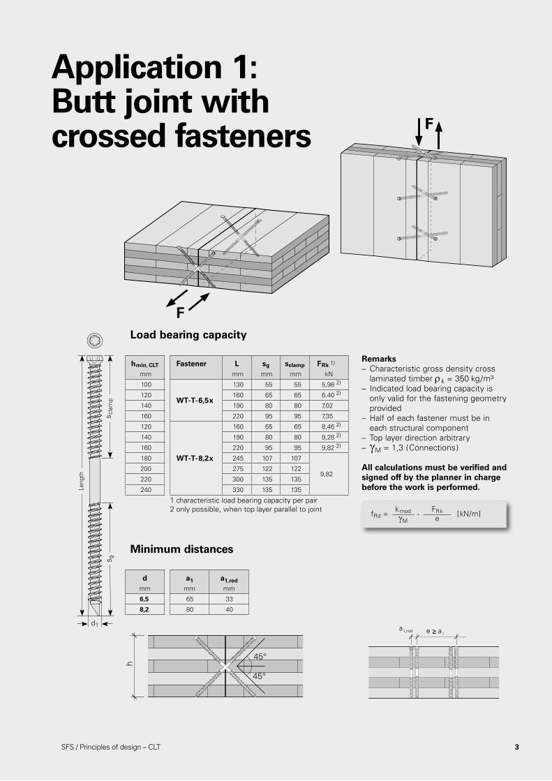
hmin, CLT Fastener L sg sclamp FRk 1)
mm mm mm mm kN
100
WT-T-6,5x
130 55 55 5,98 2)
120 160 65 65 6,40 2)
140 190 80 80 7,02
160 220 95 95 7,35
120
WT-T-8,2x
160 65 65 8,46 2)
140 190 80 80 9,28 2)
160 220 95 95 9,82 2)
180 245 107 107
9,82200 275 122 122
220 300 135 135
240 330 135 135
Application 1: Butt joint with crossed fasteners
Load bearing capacity
Minimum distances
Remarks– Characteristic gross density cross laminated timber rk = 350 kg/m³ – Indicated load bearing capacity is only valid for the fastening geometry provided – Half of each fastener must be in each structural component– Top layer direction arbitrary– gM = 1,3 (Connections) All calculations must be verified and signed off by the planner in charge before the work is performed.
d a1 a1,redmm mm mm
6,5 65 33
8,2 80 40
fRd = [kN/m]kmodgM
FRke
.
h
45°
45°
a1,red e ≥ a1
s gs s
pann
Läng
e
Long
ueur
Lung
hezz
a
Leng
th
d1
de en fr it
s g
d1
s gs p
ress
s cla
mp
d1
s gs s
erra
ggio
d1
F
FF
1 characteristic load bearing capacity per pair2 only possible, when top layer parallel to joint
3SFS / Principles of design – CLT
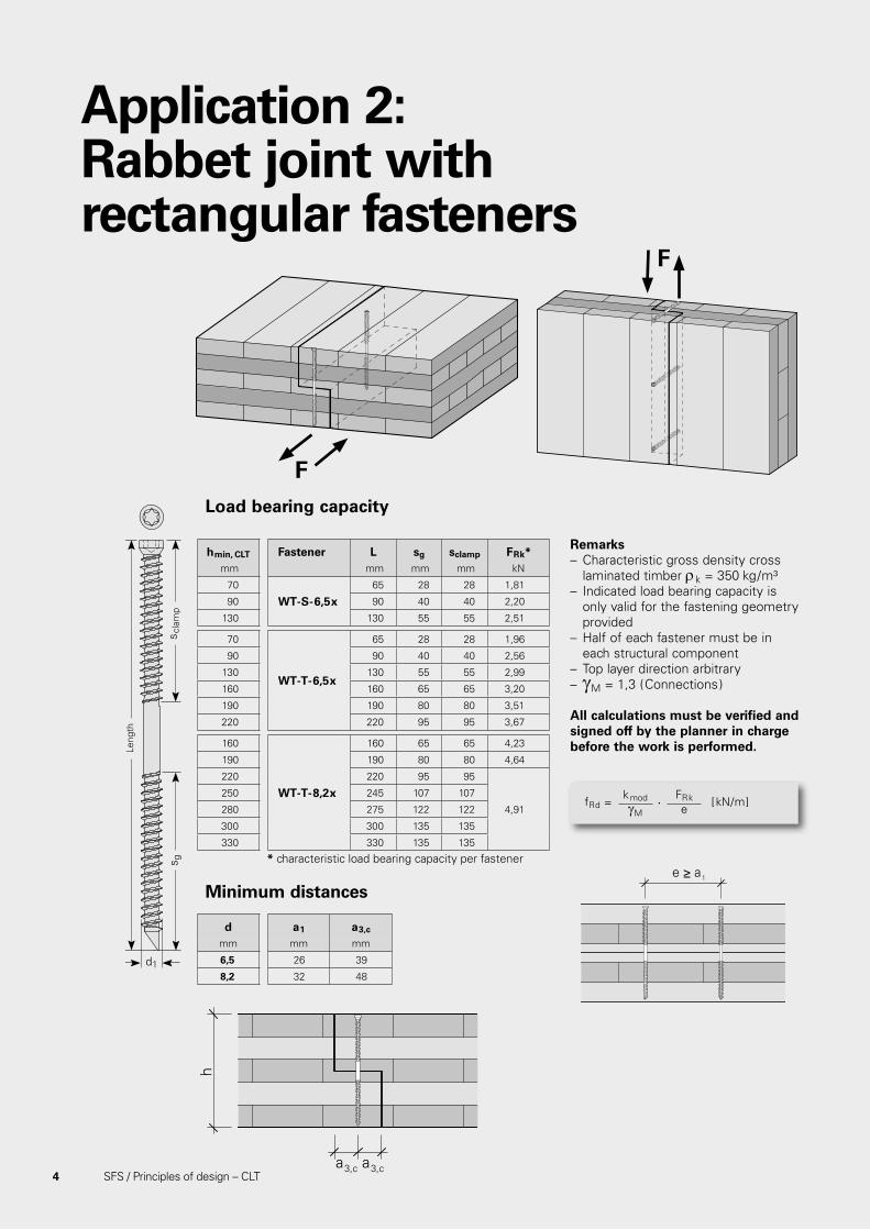
Application 2: Rabbet joint with rectangular fasteners
Load bearing capacity
Minimum distances
Remarks– Characteristic gross density cross laminated timber rk = 350 kg/m³ – Indicated load bearing capacity is only valid for the fastening geometry provided – Half of each fastener must be in each structural component– Top layer direction arbitrary– gM = 1,3 (Connections) All calculations must be verified and signed off by the planner in charge before the work is performed.
hmin, CLT Fastener L sg sclamp FRk*mm mm mm mm kN
70
WT-S-6,5x65 28 28 1,81
90 90 40 40 2,20
130 130 55 55 2,51
70
WT-T-6,5x
65 28 28 1,96
90 90 40 40 2,56
130 130 55 55 2,99
160 160 65 65 3,20
190 190 80 80 3,51
220 220 95 95 3,67
160
WT-T-8,2x
160 65 65 4,23
190 190 80 80 4,64
220 220 95 95
4,91
250 245 107 107
280 275 122 122
300 300 135 135
330 330 135 135
d a1 a3,c
mm mm mm
6,5 26 39
8,2 32 48
fRd = [kN/m]kmodgM
FRke
.
s gs s
pann
Läng
e
Long
ueur
Lung
hezz
a
Leng
th
d1
de en fr it
s g
d1
s gs p
ress
s cla
mp
d1
s gs s
erra
ggio
d1
h
a3,c a3,c
e ≥ a1
F
F
* characteristic load bearing capacity per fastener
4 SFS / Principles of design – CLT

Application 3: Rabbet joint with crossed fasteners
Load bearing capacity
Minimum distances
Remarks– Characteristic gross density cross laminated timber rk = 350 kg/m³ – Indicated load bearing capacity is only valid for the fastening geometry provided – Half of each fastener must be in each structural component– Top layer direction arbitrary– gM1 = 1,3 (Connections) – gM2 = 1,1 (Buckling)
All calculations must be verified and signed off by the planner in charge before the work is performed.
hmin, CLT Fastener L sg scalmp FRk,1* FRk,2
*
mm mm mm mm kN kN
100 WT-S-6,5x 130 55 55 5,90 6,83
100
WT-T-6,5x
130 55 55 5,90
9,66120 160 65 65 7,09
140 190 80 80 8,86
160 220 95 95 10,64
120
WT-T-8,2x
160 65 65 9,82
16,77
140 190 80 80 12,35
160 220 95 95 14,70
180 245 107 107 16,56
200 275 122 122 18,88
220 300 135 13520,89
240 330 135 135
d a1 a1,red a3,c
mm mm mm mm
6,5 26 13 33
8,2 32 16 40
fRd = min [kN/m]
kmodgM,1
1gM,2
FRk, 1e
FRk, 2e
.
.
s gs s
pann
Läng
e
Long
ueur
Lung
hezz
a
Leng
th
d1
de en fr it
s g
d1
s gs p
ress
s cla
mp
d1
s gs s
erra
ggio
d1
a1,red
h
a3,c a3,c
45°
45°
e ≥ √2• a1
a 1
F
F
* characteristic load bearing capacity per pair
SFS / Principles of design – CLT 5

6 SFS / Principles of design – CLT
Load bearing capacity
Minimum distances
Remarks– Characteristic gross density cross laminated timber rk = 350 kg/m³ – Indicated load bearing capacity is only valid for the fastening geometry provided – Values apply to connections where half of each fastener is in each structural component– Head of WR fastener flush with surface of structural component– Direction of top-layer in any order– gM = 1,3 (Connections) All calculations must be verified and signed off by the planner in charge before the work is performed.
hmin Fastener L sg sspan FRk*
mm mm mm mm kN
70 WT-S-6,5x 130 55 55 1,46
70
WT-T-6,5x
130 55 55 1,84
80 160 65 65 1,91
100 190 80 80 2,01
110 220 95 95 2,01
80
WT-T-8,2x
160 65 65 2,52
100 190 80 80 2,64
110 220 95 95 2,76
130 245 107 107 2,86
140 275 122 122 2,98
150 300 135 1353,09
170 330 135 135
fRd = [kN/m]kmodgM
FRke
.
d a1 a3,c a4,c
mm mm mm mm
6,5 65 39 33
8,2 80 48 40
9,0 90 54 45
Leng
th
d1
s gs s
pann
Läng
e
Long
ueur
Lung
hezz
a
Leng
th
d1
de en fr it
s g
d1
s gs p
ress
s cla
mp
d1
s gs s
erra
ggio
d1
a4,c a4,c
a3,c
h
e ≥ a1
F
* Characteristic load bearing capacity per fastener.
60 80 100 120 140 180 200 240
250 2,98 3,30 3,13 2,95 2,78 2,26 1,81 0,50
300 2,98 3,56 3,56 3,39 3,21 2,87 2,69 2,03
350 2,98 3,56 3,67 3,67 3,64 3,30 3,13 2,78
400 2,98 3,56 3,67 3,67 3,67 3,67 3,56 3,21
h [mm]WR-T-9xL
Linear interpolation may be applied for in-between values.
F.[kN]
Application 4: Corner joint with rectangular fasteners

SFS / Principles of design – CLT 7
Load bearing capacity
Minimum distances
Remarks– Characteristic gross density cross laminated timber rk = 350 kg/m³ – Indicated load bearing capacity is only valid for the fastening geometry provided – Values apply to connections where half of each fastener is in each structural component– Head of WR fastener flush with surface of structural component– Top layer direction arbitrary– gM1 = 1,3 (Connections) – gM2 = 1,1 (Buckling)
All calculations must be verified and signed off by the planner in charge before the work is performed.
hmin Fastener L sg sclamp FRk, 1* FRk,2*
mm mm mm mm kN kN
50 WT-S-6,5x 130 55 55 5,90 6,83
50
WT-T-6,5x
130 55 55 5,90
9,6660 160 65 65 7,09
80 190 80 80 8,86
90 220 95 95 10,64
60
WT-T-8,2x
160 65 65 9,82
16,77
80 190 80 80 12,35
90 220 95 95 14,70
100 245 107 107 16,56
110 275 122 122 18,88
120 300 135 13520,89
130 330 135 135
fRd = min [kN/m]
kmodgM,1
1gM,2
FRk, 1e
FRk, 2e
.
.
d a1 a3,c a4,c a1,red
mm mm mm mm mm
6,5 33 33 26 17
8,2 40 40 32 20
9,0 45 45 36 23
s gs s
pann
Läng
e
Long
ueur
Lung
hezz
a
Leng
th
d1
de en fr it
s g
d1
s gs p
ress
s cla
mp
d1
s gs s
erra
ggio
d1
a3,c a1,red
a4,c a4,c
h
45°
45°
e ≥ √2• a1
F
Leng
th
d1
Linear interpolation may be applied for in-between values.* characteristic load bearing capacity per pair.
FRk,1* FRk,1*
60 80 100 120 140 180 200 240 --
250 10,56 15,17 17,68 13,08 8,47 3,86 -- --
20,23300 10,56 15,17 19,78 21,22 16,61 12,01 2,79 --
350 10,56 15,17 19,78 24,38 24,76 20,15 10,94 1,72
400 10,56 15,17 19,78 24,38 28,99 28,30 19,08 9,87
hCLTWR-T-9xL
Application 5: Corner joint with crossed fasteners

8 SFS / Principles of design – CLT
Load bearing capacity
Minimum distancesRemarks– Characteristic gross density cross laminated timber / soft wood rk = 350 kg/m³ – Head of WFR fastener flush with surface of structural component– Values apply to connections where half of each fastener is in each structural component– Indicated load bearing capacity is only valid for the fastening geometry provided – Top layer direction arbitrary– gM = 1,3 (Connections)
Fastener L sg sclamp bmin,i ti [mm]
mm mm mm mm 40 45 50 60 80 100 120
WT-T-6,5xL
65 28 28 40 2,25
90 40 40 40 -- 2,87
130 55 55 40 -- 3,22
160 65 65 40 -- 3,43
190 80 80 40 -- 3,74
220 95 95 40 4,06
WT-T-8,2xL160 65 65 48 -- 4,58
190 80 80 48 -- 4,99
220 95 95 48 -- 5,40
WFR-T-6,0xL
70 39 – 60 1,65 1,53 --
80 48 – 60 1,78 1,73 1,65
90 48 – 60 1,86 1,94 1,83 1,65 --
100 54 – 60 1,86 1,97 1,99 1,83 --
110 64 – 60 1,86 1,971,99
1,65 --
120 64 – 60 1,86 1,97 1,83 --
130 64 – 60 1,86 1,971,99
1,65 --
140 64 – 60 1,86 1,97 1,83 --
150 64 – 60 1,86 1,971,99
1,65
160 64 – 60 1,86 1,97 1,83
180 64 – 60 1,86 1,97
1,99200 64 – 60 1,86 1,97
220 64 – 60 1,86 1,97
≥240 64 – 60 1,86 1,97
d a1/a2 a3,c a4,c
mm mm mm mm
6,0 72 36 30
6,5 33 39 20
8,2 40 48 24
Leng
th
d1
s gs gs s
pann
Läng
e
Long
ueur
Lung
hezz
a
Leng
th
d1
de en fr it
s g
d1
s gs p
ress
s cla
mp
d1
s gs s
erra
ggio
d1
a 3,c
a3,c
a 4,c
a 4,c
a4,ca4,c
e2 ≥ a2
e1 ≥ a1
F
fRd = min [kN/m]
kmodgM
kmodgM
FRk, 1e1
FRk, 2e2
.
.
t1 / b2
t 2 /
b 1
FRk,i [kN]
Application 6: Corner joint with shoring timber and rectangular fasteners
All calculations must be verified and signed off by the planner in charge before the work is performed.
9SFS / Principles of design – CLT
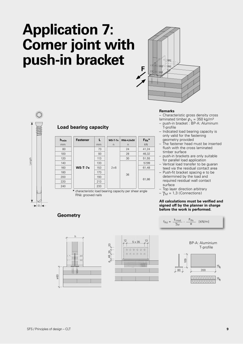
Load bearing capacity
Geometry
Remarks– Characteristic gross density cross laminated timber rk = 350 kg/m³– push-in bracket : BP-A: Aluminum T-profile– Indicated load bearing capacity is only valid for the fastening geometry provided– The fastener head must be inserted flush with the cross laminated timber surface – push-in brackets are only suitable for parallel load application– Vertical load transfer to be guaran teed via the residual contact area– Push-fit bracket spacing e to be determined by the load and required residual wall contact surface – Top layer direction arbitrary– gM = 1,3 (Connections) All calculations must be verified and signed off by the planner in charge before the work is performed.
hmin Fastener L WS-T-7x RNä-4,0x50 FRk*mm mm n n kN
80
WS-T-7x
73
2x6
24 41,24
100 93 28 46,32
120 113 30 51,55
140 133
36
57,99
160 153 61,48
180 173
61,86200 193
220 213
240 233
fRd = [kN/m]kmodgM
FRke
.
Leng
th
d1
≥60
h
12
2035
48 6
5 x 3512 13
80 200
6
109
6
BP-A: Aluminium T-profile
F
* characteristic load bearing capacity per shear angle RNä: grooved nails
Application 7: Corner joint with push-in bracket

Load bearing capacity
OSB/3 3-ply panel Kerto-Q Plywood
hmin, CLT Fastener L sg FRk* FRk* FRk* FRk*mm mm mm kN kN kN kN
50
WFR-4,0x50 30 0,82 0,77 0,75 0,77
60 60 350,93 0,91 0,88
0,91
70 70 35 0,91
50
WFR-4,5x50 29 0,95 0,90 0,88 0,91
60 60 34 1,13 1,07 1,05 1,07
70 70 39 1,14 1,11 1,07 1,11
50
WFR-5,0x50 27 1,12 1,08 1,05 1,08
60 60 32 1,30 1,24 1,19 1,25
70 70 37 1,40 1,37 1,26 1,38
50
WFR-6,0x
50 29 1,43 – – –
60 60 34 1,57 1,52 1,45 1,58
70 70 39 1,75 1,69 1,62 1,74
80 80 481,76 1,74 1,64 1,81
90 90 48
F
Leng
th
d1
s g
* characteristic load bearing capacity per fastener
10 SFS / Principles of design – CLT
Application 8: Single-sided fish plate with rectangular fasteners

Load bearing capacity
Remarks– Characteristic gross density cross laminated timber rk = 350 kg/m³ – The WFR fastener head must be inserted flush with the cross laminated timber surface– Indicated load bearing capacity is only valid for the fastening geometry provided– OSB/3 d = 25 mm according to EN 13986 3-ply panel d = 27 mm according to EN 13986 Kerto-Q d = 27 mm according to Z-9.1-100 Plywood d = 27 mm according to EN 13986– Timber cover direction EWP arbitrary – cross laminated timber cover direction arbitrary – Plates must be specially verified if two or more fastener rows are used– gM = 1,3 (Connections)
All calculations must be verified and signed off bythe planner in charge before the work is performed.
hCLT OSB/3 3-ply panelmm 25 27
d a1 a3,c, EWP a3, c a1 a3, c,EWP a3,c
mm mm mm mm mm mm mm
4,0 16 12 24 16 24 24
4,5 18 14 27 18 27 27
5,0 20 15 30 20 30 30
6,0 24 18 36 24 36 36
hCLT Kerto-Q Plywoodmm 27 27
d a1 a3, c,EWP a3,c a1 a3,c, EWP a3,c
mm mm mm mm mm mm mm
4,0 60 20 24 16 12 24
4,5 68 23 27 18 14 27
5,0 75 25 30 20 15 30
6,0 90 30 36 24 18 36
fRd = [kN/m]kmodgM
FRke
.
a3,c,EWP a3,c,EWP
a3,c
h
a3,c
e ≥ a1
11SFS / Principles of design – CLT
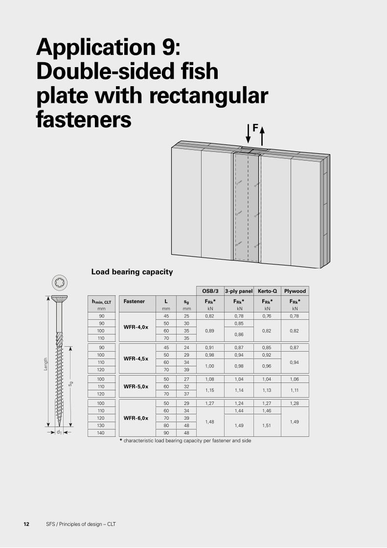
Application 9: Double-sided fish plate with rectangular fasteners
SFS / Principles of design – CLT 12
Load bearing capacity
OSB/3 3-ply panel Kerto-Q Plywood
hmin, CLT Fastener L sg FRk* FRk* FRk* FRk*mm mm mm kN kN kN kN
90
WFR-4,0x
45 25 0,82 0,78 0,76 0,78
90 50 30
0,89
0,85
0,82 0,82100 60 350,86
110 70 35
90
WFR-4,5x
45 24 0,91 0,87 0,85 0,87
100 50 29 0,98 0,94 0,92
0,94110 60 341,00 0,98 0,96
120 70 39
100
WFR-5,0 x50 27 1,08 1,04 1,04 1,06
110 60 321,15 1,14 1,13 1,11
120 70 37
100
WFR-6,0x
50 29 1,27 1,24 1,27 1,28
110 60 34
1,48
1,44 1,46
1,49120 70 39
1,49 1,51130 80 48
140 90 48
F
Leng
th
d1
s g
* characteristic load bearing capacity per fastener and side

13SFS / Principles of design – CLT
Minimum distances
Remarks– Characteristic gross density cross laminated timber rk = 350 kg/m³ – The WFR fastener head must be inserted flush with the cross laminated timber surface– Indicated load bearing capacity is only valid for the fastening geometry provided– OSB/3 d = 18 mm according to EN 13986 3-ply panel d = 20 mm according to EN 13986 Kerto-Q d = 21 mm according to Z-9.1-100 Plywood d = 18 mm according to EN 13986– Timber cover direction HWS arbitrary – cross laminated timber cover direction arbitrary – Plates must be specially verified if two or more fastener rows are used– gM = 1,3 (Connections)
All calculations must be verified and signed off bythe planner in charge before the work is performed.
hEWP OSB/3 3-ply panelmm 18 20
d a1 a3,c, EWP a3,c a1 a3,c, EWP a3,c
mm mm mm mm mm mm mm
4,0 16 12 24 16 24 24
4,5 18 14 27 18 27 27
5,0 20 15 30 20 30 30
6,0 24 18 36 24 36 36
hEWP Kerto-Q Plywoodmm 21 18
d a1 a3,c, EWP a3,c a1 a3,c, EWP a3,c
mm mm mm mm mm mm mm
4,0 60 20 24 16 12 24
4,5 68 23 27 18 14 27
5,0 75 25 30 20 15 30
6,0 90 30 36 24 18 36
fRd = [kN/m]kmodgM
2·FRke
.
a3,c,EWP a3,c,EWP
a3,c
h
a3,c
e ≥ a1
FRk = characteristic load bearing capacity per fastener and side

General spacing of fasteners in CLT cross laminated timber
14 SFS / Principles of design – CLT
Crossed fastening below 45° in edge faces ( lateral)
Fastening below 90° in edge faces ( lateral)
Fastening below 90° in side faces ( lateral)
Sv,
o
a4,c
a 1
Sv,
o
a3,c
a 2
a1 4 . d
a2 2,5 . d
a3,c 6 . d
a4,c 2,5 . d
a1 10 . d
a3,t 12 . d
a3,c 7 . d
a4,c 5 . d
a1 10 . d
a3,t 12 . d
a3,c 7 . d
a4,c 5 . d
a3,c,SF 5 . d
a4,c,SF 2,5 . d
a4,ca4,c a1a3,c a3,t
S
Sv,o
a4,c
a 4,c
,SF
S S
a3,c a1
a1,red
a3,t
Sv,o
a4,c
a 3,c
,SF
S S
a3,c a1
a1,red
a3,t
Sv,o
Load in direction DL
Load in direction QL

SFS / Principles of design – CLT 15
Crossed fastening below 45° in side faces (axial)
Crossed fastening below 45° in edge faces (axial)
a1 4 . d
a2 2,5 . d
a1,c 5 . d
a2,c 2.5 . d
a1,CG 5 . d
a2,CG 4 . d
a1 5 . d
ac 4 . d
aCG 5 . d
a2,reda2,c
a1,reda1,c
aredac
a 2,C
G a1,CG
a1,CG
a 2,C
G
Sv,oSS
a 1
a 2,C
G a2,CG
a2,CG
a 2,C
G
Sv,oSS
a 2
a CG
aCGaCG
Sv,o
S S
a 1
Load in direction DL
Load in direction QL
Remarks– ai,red = max { 1,5 · d; (1 - αk /180) · ai } mit αk = 90° – S = center of gravity
All calculations must be verified and signed off by the planner in charge before the work is performed.

16 SFS / Principles of design – CLT
Convincing advantages:n simple, reliable calculationn diverse range of applicationn durable joints with high load-bearing capacityn fast, efficient installation without pre-drillingn form-fitting joint due to double thread n high aesthetic standard due to countersunk fastener
Performance with comprehensive benefits for you
n Reductions in time and costStructural timber elements are joined with the special fasteners in a single operation, without pre-drilling. Installation is simple and secure using the recom-mended tools.
n Wide range of applicationApplications which have been impossible to date can also be implemented with these systems.
n Secure jointsScrewed joints are invisible and thus aesthetically pleasing. The fastener is also largely protected against corrosion and against heat in the event of fire.
n Principles of calculationDetailed planning documentation catering for a very wide range of applications ensures easy, reliable calcu lation. For special applications our structural timberwork consul tants will be pleased to assist you in selecting the most efficient and cost-effective fastening method.
for universal application in structural timberwork
The proven fastening systems
© S
FS F
ebru
ary
2018
. Sub
ject
to
tech
nica
l mod
ifica
tions
and
pric
e ch
ange
s. P
rinte
d in
Sw
eden
. C
LT-P
rinci
ple
of d
esig
n 20
18. T
echn
ical
cha
nges
res
erve
d. C
reat
ed in
Sw
eden
. The
det
ails
sta
ted
are
resu
lts o
f te
sts
and/
or c
alcu
latio
ns a
nd t
here
fore
are
non
-bin
ding
and
do
not
repr
esen
t gu
aran
ties
or w
arra
nted
cha
ract
eris
tics
for
not
spec
ified
app
licat
ions
. All
calc
ulat
ions
the
refo
re h
ave
to b
e ch
ecke
d an
d ap
prov
ed b
y th
e re
spon
sibl
e pl
anne
r ah
ead
of e
xecu
tion.
The
use
r is
res
pons
ible
to
assu
re c
ompl
ianc
e w
ith a
ll ap
plic
able
law
s an
d re
gula
tions
.
SFS Olivehällsvägen 10 SE-645 42 Strängnäs T +46 (0)-152 71 50 00
[email protected] [email protected] www.sfsintec.biz/se