Embed Size (px)
Citation preview

Principles of an automatic brewing machine
By using CodeSys with Raspberry Pi
Daniel P. Mårtensson

ii
This page is left blank
iii
1 Foreword Thanks to my father, Per Mårtensson, which helped me to cutting out all this plate and bend plates so
I have material to work with. Without him, I would never ever have finished this project. I want to
thank my sister and my mother for supporting me during this project.
And thanks to Dr. Sven Rönnbäck, which is a very good and smart technical lecturer.
Daniel Mårtensson Örnsköldsvik, Jaunary, 2017

iv
Table of Contents Foreword ................................................................................................................................................. iii
Abstract ................................................................................................................................................... vi
Introduction ............................................................................................................................................. 1
The Projects presentation ................................................................................................................... 1
The PLC ............................................................................................................................................ 1
The scaffolding ................................................................................................................................ 2
The presentation of previous research ........................................................................................... 2
The presentation about history and fundamental methods of brewing ............................................ 3
The history of brewing .................................................................................................................... 3
The fundamental methods of brewing............................................................................................ 4
The aim for the project............................................................................................................................ 4
Purpose ................................................................................................................................................ 4
Goal ..................................................................................................................................................... 5
The schedule ....................................................................................................................................... 5
Principal explanations and practical methods ........................................................................................ 5
The mechanical construction .............................................................................................................. 5
The idea behind the scaffolding ...................................................................................................... 5
The hops container .......................................................................................................................... 7
The motorized whisks .................................................................................................................... 10
The heat exchanger ....................................................................................................................... 12
The rest of the pipe system ........................................................................................................... 13
The control system ............................................................................................................................ 18
The servo system ........................................................................................................................... 18
The cooling system ........................................................................................................................ 23
The drain system ........................................................................................................................... 26
The heating system ....................................................................................................................... 29
The sensors locations .................................................................................................................... 34
The PLC task and run time order ................................................................................................... 35
Results ................................................................................................................................................... 37
The scaffolding walkthrough ............................................................................................................. 37
The PLC control box ........................................................................................................................... 51
Reflections ............................................................................................................................................. 59
Reflections about the mechanical design ......................................................................................... 59

v
The cooler system ............................................................................................................................. 59
The heat exchanger ........................................................................................................................... 59
The hops container ............................................................................................................................ 59
The heating system ........................................................................................................................... 59
The drain system ............................................................................................................................... 60
The motorized whisk ......................................................................................................................... 60
The locations of the temperature sensors ........................................................................................ 60
EMC disturbing .................................................................................................................................. 60
The control box ................................................................................................................................. 60
PID controlling inside this PLC ........................................................................................................... 61
Social and Ethical aspects of the work .............................................................................................. 61
Advantages by internet connection .................................................................................................. 61
Advantages by automation ............................................................................................................... 61
Simulink PLC Coder ............................................................................................................................ 62
Conclusion and Recommendations ....................................................................................................... 62
References ............................................................................................................................................. 63
Appendix................................................................................................................................................ 64
A......................................................................................................................................................... 64
B ......................................................................................................................................................... 65
C ......................................................................................................................................................... 66
D ........................................................................................................................................................ 67
E ......................................................................................................................................................... 68

vi
2 Abstract This project will give you a view from another side when it comes to control engineering and
mechanical construction in brewing.
This is a thesis project about principles for an automatic brewing machine. This project started off
with prestudy of earlier research results in automatic brewing based on the Arduino platform.
This project shows principles about mechanical construction and creating a control system by using
inexpensive commercial products such as CodeSys and Raspberry Pi.
The project report begins describing the mechanical construction, how it works and it shows how it
looks. The mechanical construction is a tall scaffolding which is the chassis of the brewing machine.
The history background about brewing is reviewed and the fundamental methods about brewing are
described as well. The goal of this project is to present principals by using CodeSys and Raspberry Pi
together. Notice that this is not a construction document. This document does not include
production wiring diagrams or blueprints – only principles of wiring diagrams and figures of the
machine, designed in a CAD software.
This brewing machine includes a few different kind of control systems to automate the process. The
processes are a hops container that can deliver a set of hops in a specific time, motorized whisks to
distribute the heat, heat exchanger for cooling down, heating control system and a drain control
system.
The main focus in this project is the mechanical parts, the flow system, the control systems and a
discussion about each sub system. Results shows a lot of pictures of the complete system with text
that explain the pictures. What was good, what was bad and what could be done better.

1
3 Introduction This section is an introduction about this project, previous research and history of brewing.
3.1 The Projects presentation This project present a construction and principles about an automatic brewing machine which is
programed with CodeSys[ 1]. The brewing machine is automatically controlled with a PLC
[ 2] and the machine is built on a lightweight scaffolding which is made of aluminum.
3.1.1 The PLC A PLC is a computer that can handle input and output signals. The input and output are often
referred as I/O, e.g. I/O-pins, which are describing the input and output pins for the PLC. The PLC’s
task is about controlling the machine with the I/O-pins. The PLC can receive signals about
temperature from a temperature sensor or flow rate from a flow sensor, and the PLC can send high
and low digital signals to control relays, which further control external mechanical devices e.g. water
pumps, rotating motors, a heating element and servos. The PLC can be controlled by a PC (Personal
computer) by using a webpage which is hosted on the PLC itself through and DHCP server. The PLC is
encapsulated inside a control box as a protection to prevent dust and other types of harmful objects
to cause damage on the electronics inside the control box. Figure 1 shows the project’s PLC inside its
own control box. The I/O-pins of the PLC are available inside the control box. This PLC is a Raspberry
Pi[ 3], model B+, but is called a PLC due to the software which is going to be used to program the
logic inside this Raspberry Pi B+.
Figure 1: The Raspberry Pi B+

2
3.1.2 The scaffolding The brewing machine contains four equal sized buckets. The buckets are the most important objects
in this entire project. Without those buckets, it will be no machine at all because something must
carry and store a liquid. The buckets are standing above on each other to take advantage of the Earth
gravity. Due to the gravity, no pumps are required to transport the liquid from a bucket to another
bucket, except when cooling system is active and the recirculating system is active. That system will
later be introduced in this report.
Figure 2 shows the scaffold with buckets on in each floor. The purpose why the reason the buckets
are standing above each other are because liquid objects are going to stream from a bucket above to
a bucket below, due to a hole center in the bottom of each bucket, except the bucket at the bottom
of the scaffolding. That bucket has no hole at all. In the section “3.2 The presentation about history
and fundamental methods of brewing” explains why the liquid needs to stream from a bucket to
another bucket.
Figure 2: An early construction of the scaffold with four buckets
3.1.3 The presentation of previous research There have been a lot of previous research in automatic brewing – as a hobby or as a commercial
manufacturing. The commercial manufacturing are often labeled as process engineering in brewing.
Various types of control systems and control methods have been used to find a solution for make the
whole process automatic.
The most commonly used control unit for automatic brewing when it comes to small hobby
breweries is Arduino[ 4]. Arduino is a low cost microcontroller based on Atmel’s[ 5] programmable
microprocessors for controlling external devices e.g. LCD, mechanical devices, other types of
integrated circuits or receive information about an environment by using I/O-pins. The Arduino
comes in different models such as Arduino UNO, Arduino MEGA 2560, Arduino Micro, Arduino Nano
etc, depending on the requirements from the user.

3
Article[ 6] from Georgia State University U.S.A, present an introduction about fundamentals in
automatic brewing by using Arduino UNO. The article describes the principles about how to setup an
automatic brewing machine. Different types of control methods such as ON/OFF controlling and
proportional, integrative and derivative (PID) are basically described inside that article as well. To
control the brewing machine using the control methods, a laptop, pump, relay and a heat exchanger
have been used. Figure 3 shows a fundamental example of an automatic brewing machine by using
an Arduino. The conclusion about this previous research is that small breweries can use low cost
control systems and PID controlling, such as the article describes, to automate the process.
3.2 The presentation about history and fundamental methods of brewing
3.2.1 The history of brewing Making beer is a very old method, and it has been practice over many centuries. But making beer as
always been done by hand due the lack of knowledge of control engineering. The earliest
documented[ 7] mass production of beer can be found at the medieval monastery in the 17th
century. At that time, beer begun to be a very popular product, more than before, so the production
increased so much so that in the early 19th century automatic brewing where introduced. The
industrial revolution began in late 19th that was the starting point of the requirements for industrial
automation. In the 19th century there was no computer, so everything needed to be analogue and
mechanical. But since the late 20th century, proportional, integrative and derivative (PID)[ 8]
technique and altering current was invented, the automatic production of beer got its modern shape.
Figure 3: Picture from the article[ 6]

4
3.2.2 The fundamental methods of brewing The basics of brewing can be done in these 8 steps.
1. Mix in malt and water in a malt bucket.
2. Heat up that malt bucket to 65-70°C over 60 minutes. The number of minutes depends of
what kind of malt is used. When the malt and water are mixed together it’s called wort – non
yeasted beer.
3. After 60 minutes, transfer the wort from the malt bucket to a boiler bucket at the same time
water of 78°C are streaming into the malt bucket from a water bucket. The volume in the
malt bucket must remain constant. The malt cannot be dried out.
4. When desired amount of wort is collected inside the boiler bucket, the wort is heated up so
it starts boiling.
5. When the wort inside the boiler bucket is starting to boil. Add hops in different amount in
different time moments. The total time to boil is about 60 minutes, or more, depending on
which hops that are used.
6. After the wort in the boiler bucket has been boiled, including hops, it’s time for cooling down
the wort.
7. When the wort has been cooled down to between 14 and 20°C, it’s is time to add in yeast.
8. It takes about 2 weeks to yeast the wort into beer.
4 The aim for the project In this section, the aim and the goal are described.
4.1 Purpose The purpose with this project is to go through the principles of how to build an automatic brewing
machine by using low cost PLC such as Raspberry Pi. The project will explore how far a user can go by
using PLC standard IEC-61131-3[ 9] programming language.
In modern education, there is a lack of knowledge when it comes to PLC education. Not because the
severity to learn PLC coding, but because of methods and software to use in education. Newly
graduated engineers haven’t high skill in PLC programming because of that. This SWOT-analysis from
table 1, explains the strength, benefits, threat, disadvantages of the results about newly graduated
engineers from the universities (from my point of view).
Table 1: SWOT- analysis
Strength - Has knowledge about theory - Has the ability to work in projects - Has a wide education
Disadvantages - Lack of effectiveness - Market asking for practice - Market asking for engineers which
using their products
Benefits - Cooperative - The choose between engineers being
bigger due to wide education
Threat - Newly graduated has much to learn
before he/she will be effective - Schools have a limited economic budget
5
That’s why this project is made – to increase methods and principles about how to create projects
with PLC by using low cost education tools. The receiver of this report is Department of Applied
Physics and Electronics at Umeå University[ 10] in Sweden.
4.2 Goal This is the project goals.
1. Show principles of mechanical construction of the automatic brewing machine
2. Create a control panel for the PLC
3. Use Simulink PLC coder to generate algorithms for use in IEC 61131-3 PLC code
4. Use temperature and flow sensors with the PLC
5. Use P and PID controller to control the processes
6. Show the process in details how brewing works
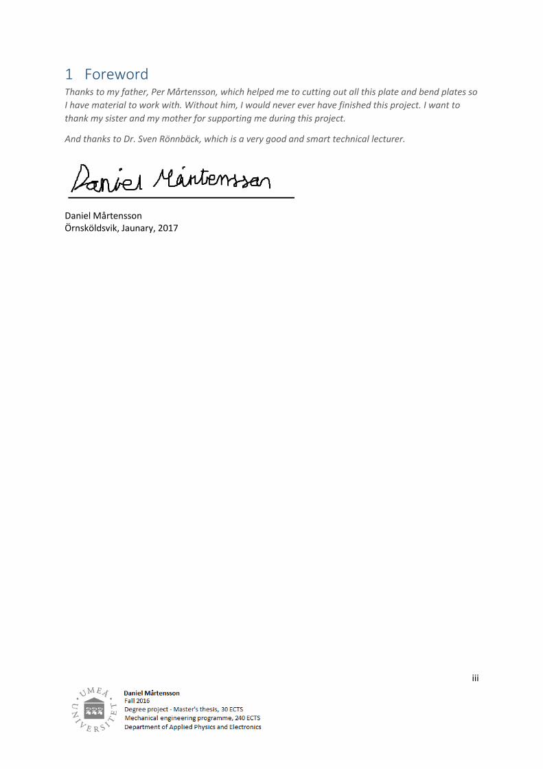
4.3 The schedule Table 2 shows the of projects schedule.
Table 2: Schedule
Operation\Time in weeks 1 2 3 4 5 6 7 8 9 10
11
12
13
14
15
16
17
18
19
20
Analysis
Manufacturing of blueprints
Build the prototype
Implementation of controllers
Test, tuning and run
Programming
Report writing
Examination
Accounting
5 Principal explanations and practical methods In this section, principal explanations and practical methods about control engineering are described.
Also practical construction such as electric engineering and mechanical engineering is described as
well.
5.1 The mechanical construction This part presents the methods and idea behind the mechanical construction.
5.1.1 The idea behind the scaffolding The step numbers 1 to 7 in section “3.2.2 Fundamental methods of brewing”, describes the whole
process. All steps are required transportation of wort from a bucket to another bucket and it can be
done by letting the wort streaming by taking advantage of the gravity. That’s why a scaffolding is
required so the scaffolding can hold up each bucket in different levels.

6
The idea behind the scaffolding is that the scaffolding shall be portable and no welding or bolts are
required to assembly the scaffolding. Only the pipes and heat exchanger are welded due to prevent
leakage.
Figure 4 shows that the scaffolding can be assembled down or up by mounting the walls inside
rectangular jacks and holes so the walls can fit into in each other.
Figure 4: The scaffold’s walls
Figure 5 shows the last revision of the scaffolding’s complete construction. The scaffolding’s length
are about 2.5 meters tall.
Figure 5: The whole scaffold assembled - a closer look
7
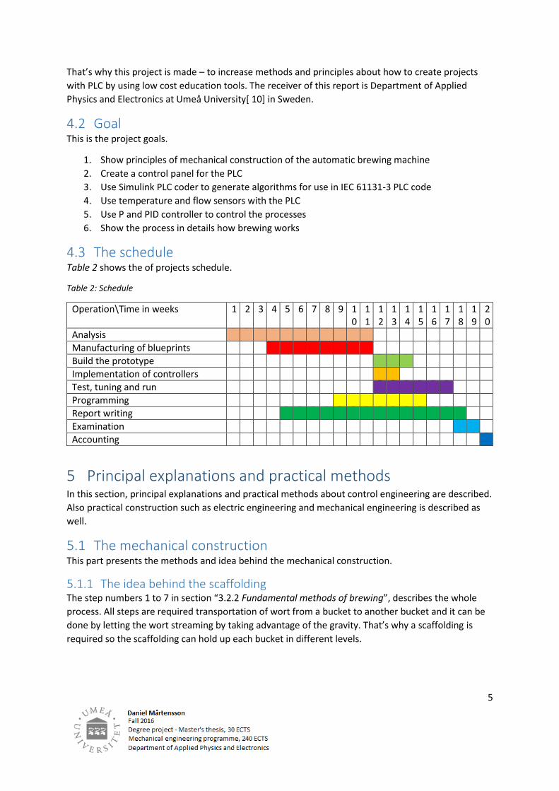
Figure 6 shows that each floor of the scaffolding constitutes of square plates with rectangular holes.
The floor plate has the same fitting idea as the walls have.
Figure 6: The scaffolding’s floors plate
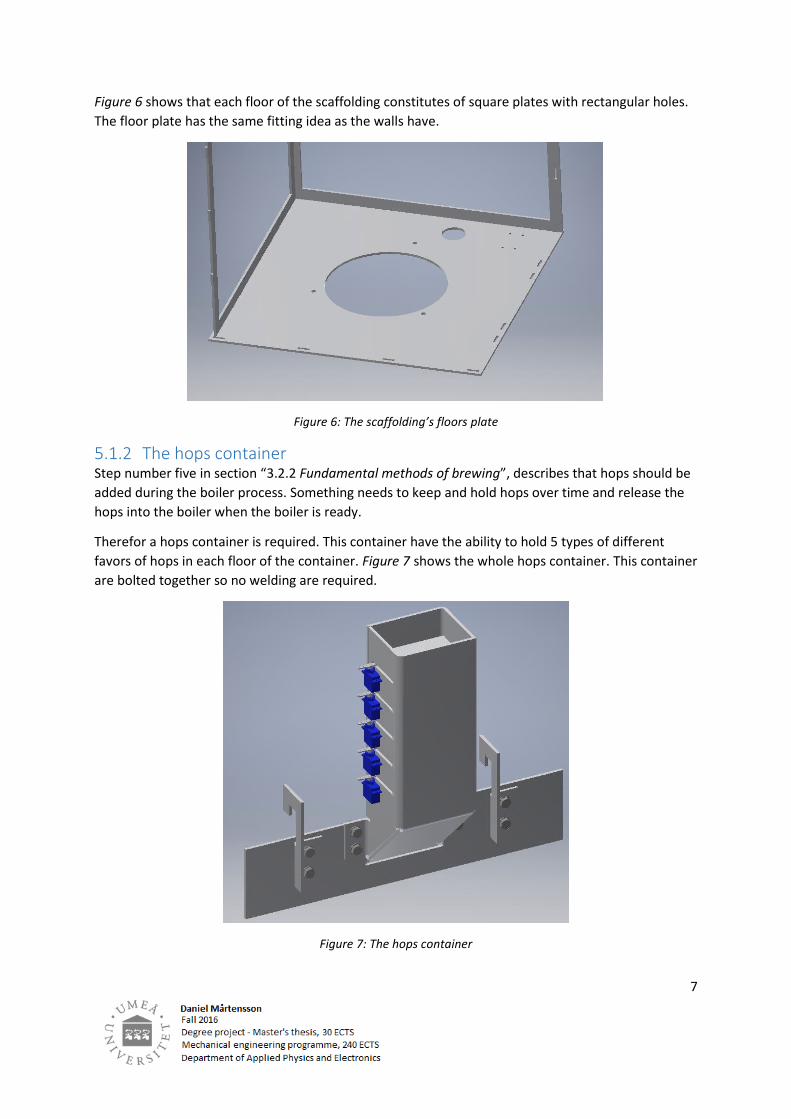
5.1.2 The hops container Step number five in section “3.2.2 Fundamental methods of brewing”, describes that hops should be
added during the boiler process. Something needs to keep and hold hops over time and release the
hops into the boiler when the boiler is ready.
Therefor a hops container is required. This container have the ability to hold 5 types of different
favors of hops in each floor of the container. Figure 7 shows the whole hops container. This container
are bolted together so no welding are required.
Figure 7: The hops container

8
Figure 8 shows when container’s side is removed temporary and it reveals what is inside. There are
five floors in form of plates with cylindrical shafts, which gives a plate the ability to rotate when the
servo arm rotates.
Figure 8: The inner side of the hops container
Figure 9 shows when the servo arms rotates, then the plates are falling down.
Figure 9: Closer look at the plates when servo arm rotates

9
Figure 10 shows another view of the hops container while one side is temporary removed.
Figure 10: Another view
Figure 11 shows the whole hops container is attached on the scaffolding by the hooks. The two
hooks are hanging on the corner of scaffolds walls and the hooks are then bolted to the flat holder
plate, which is labeled as container holder.
Figure 11: The whole hops container

10
5.1.3 The motorized whisks To make the heat equality distributed in each bucket, when the bucket if filled with malt and water
or only water, a motorized whisk is required to create rotation into the medium, will be applied.
Without the whisk, more heat will be more concentrated to specific spots in the bucket, which will
cause wrong sensor readings. More about temperature and sensors in section “5.2 The control
system”.
Figure 12 shows two motorized whisks, one for the malt bucket below and one for water bucket
above. The whisks are different due to different inertia inside the liquid. The whisks are sloping in a
differently angle depending on medium it should be into. The whisk above is for water only(large
inclination) and the whisk below is for malt and water together(small inclination). The whisk for the
malt bucket is driven by motor 1(below) and the whisk for the water bucket is driven by motor
2(upper).
Figure 12: Motorized whisks

11
Figure 13 shows a closer look of the motors. Both motors and the engine mount are the same, it’s
only the whisks angle which differ. The motors are window motors from a car.
Figure 13: A closer look at the engine mount
Figure 14 shows one silver adapter and one grey shaft with a thread. They are necessary so the
mounting the whisk.
Figure 14: The shaft and adapter on the motor

12
5.1.4 The heat exchanger To cool down a liquid medium, most of the times, a heat exchanger is required. A heat exchanger
works as an element with two types of cells which are crossing each other. One type of cells are hot
and the other type of cells are cold.
In this case, there will be a long sloping pipe which dives into a bath of cold water. Figure 15 shows
the back side and the front side of the heat exchanger. The blue arrow is the inlet for cold water, the
light blue arrow is the outlet drainage. The red arrow is the inlet for hot medium and the orange
arrow is the outlet for medium which is cooled down. In this case, hot wort from the boiler will
stream into the inlet where the red arrow points and come and the outlet is pointed out by the
orange arrow. It’s very important that all pipes from a sloping plane.
Figure 15: Heat exchanger
Figure 16 shows that all pipes and elbows are sloping down.
Figure 16: The pipes are sloping
13
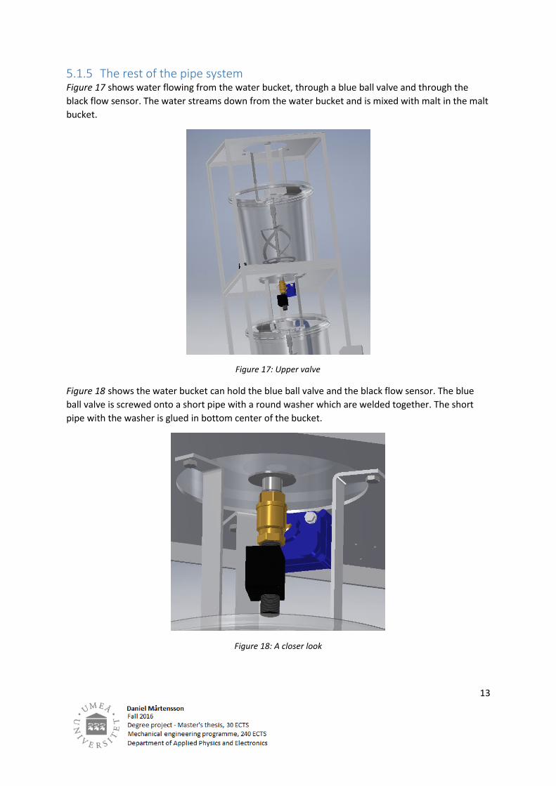
5.1.5 The rest of the pipe system Figure 17 shows water flowing from the water bucket, through a blue ball valve and through the
black flow sensor. The water streams down from the water bucket and is mixed with malt in the malt
bucket.
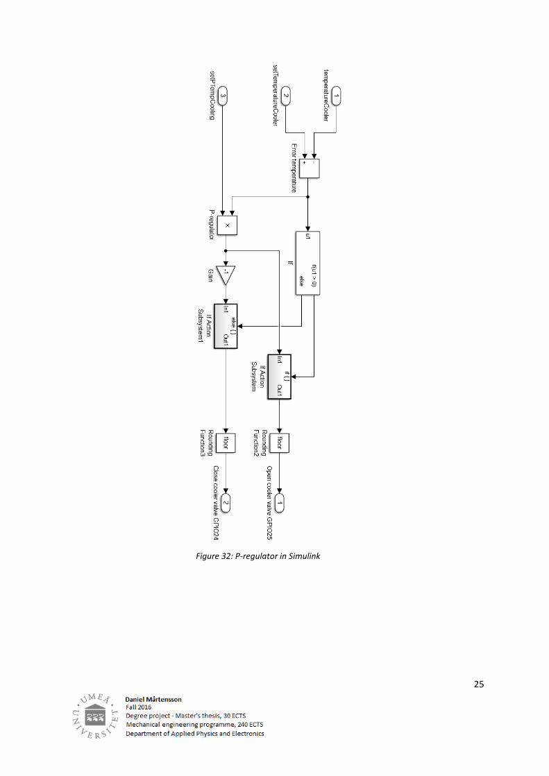
Figure 18 shows the water bucket can hold the blue ball valve and the black flow sensor. The blue
ball valve is screwed onto a short pipe with a round washer which are welded together. The short
pipe with the washer is glued in bottom center of the bucket.
Figure 18: A closer look
Figure 17: Upper valve

14
Figure 19 shows the malt bucket. This bucket contains malt and water. When it’s time to drain the
wort from malt bucket, the black recirculating pump in is recirculating the wort before, so no
particles in the malt bucket will be flowing out with the wort when the blue ball valve is opening. The
first amount of wort is not clean. Recirculating wort before the drain process will results clean wort
with no particles get stuck inside the flow sensor, because the malt works as a filter.
Figure 20 shows a closer look at the recirculating pump.
Figure 19: A closer look
Figure 20: The recirculating pump

15
Figure 21 shows when the pump recirculate, the blue ball valve is open and wort is now flowing
through the red/black flow sensor. The liquid which is streaming is from the malt bucket and is
streaming into the boiler bucket.
Figure 22 shows the bottom valve which is under the boiler bucket. The medium from the boiler
bucket is flowing from the valve into the heat exchanger through the blue hose.
Figure 21: T-pipe under middle bucket
Figure 22: The bottom valve under the boiler bucket.

16
Figure 23 shows the end of the pipe system. The bucket is collecting the medium from the heat
exchanger.
.
Figure 24 shows the storage bucket with cold water which is going to hold the cooling medium for
the heat exchanger. The black pump which also a recirculating pump which is filling the heat
exchanger with cold water.
Figure 23: The end of the pipe system
Figure 24: Water pump

17
Figure 25 explains the workflow of the whole pipe system in one picture. The first bucket is the water
bucket, the second bucket is the malt bucket, the third bucket is the boiler bucket and the fourth
bucket is the bucket which collect the wort. The bucket to the left is the cooler bucket. That bucket
holds cold water. The cold water being pumped into the heat exchanger, and back to the bucket
again thought the drainage.
Figure 25: The whole pipe system

18
5.2 The control system This parts presents principles and control methods for the whole control system.
5.2.1 The servo system A important ingredients in beer is hops and that’s why this machine have a hops container which can
drop hops into the boiler. To control the hops container, servos are used, and to build and control
the servos, a classic 555 timer[ 11] system has been used. The 555 timer creates pulse width
modulation(PWM) signals. Figure 26 shows different PWM signals through an oscilloscope when the
relay switched OFF or ON. RV1 and RV2 are potentiometers which can resize the width of the
frequency. The PLC is controlling the switch with a mechanical relay. If the relay is open, the period
of the PWM signal are going to be long, and if the relay is closed, the period of the PWM signal is
going to be small.
Figure 26: The servo driver – When the switch is off

19
To calculate what frequency the servos need to have to do a 90° degrees rotation and the Arduino
board has been used. Here is a short C-code which generate pulse width modulation pulses. When
the mechanical relay switch is ON, the high pulse is about 1300 microseconds high and 31000
microseconds low. When the mechanical relay switch is OFF, the high pulse is about 2300
microseconds high and 31000 microseconds low.
When relay is ON = The relay is ON the servo is at position 0°.
When relay is OFF = The relay is ON the servo is at position 90°.
/* Arduino servo tester */
int ON = 1246; // 1246 or 2332 Microseconds
int OFF = 31000; // Microseconds
int pin = 8; // Output pin
void setup()
{
pinMode(pin, OUTPUT); // Setup for pin 8 as digital output
}
// the loop routine runs over and over again forever:
void loop()
{
digitalWrite(pin, 1); // Pin 8 high
delayMicroseconds(ON); // Delay ON for 1246 us
digitalWrite(pin, 0); // Pin 8 low
delayMicroseconds(OFF); // Delay OFF for 31000 us
}
Figure 27 illustrates how a servo works. A servo always want high and low pulses and those pulses
represent a specific position in degrees.
Figure 27: The illustration of the servos position

20
In this project, all I/O-pins have been used and the PLC has limited I/O pins. To solve this problem,
the PLC needs to increase its output pins for the servos. To control all servos, a shift(74HC595)
register[ 12] have been applied. A shift register works as a external PLC which handle its own output
pins. The shift register only needs high and low pulses, which works as communication, from the RPi
PLC.
Figure 28 shows the “Clock” pulse and the data sent to the eight bit shift register. That means that
output 1 at the shift register going to be high when the “Latch” goes high. The PLC can shift in bits
into the shift register when the “Latch” is low, the PLC can talk to the shift register, else not. The PLC
is talking to the shift register through SPI-communication[ 13].
Figure 28: How a shift register works

21
A combination with the shift register and a Darlington[ 14] array(ULN2003) of transistors. Figure 29 shows the Darlington array, and if input 1B gets a high signal from the shift register, the output 1C
going to be act like it was ground(low output), else a high output. A Darlington array does invert
signals, but together with the shift register, it will work as signal amplifier.
Figure 30 shows the combination of 555 timer system, with the shift register and the Darlington
array. The five servos can be controlled from the PLC. The current in this circuit comes from the 555
system, to the servos and then to the Darlington array. If the shift register’s output gives a high signal
to the Darlington array so the Darlington works as a ground for the current from the 555 system.
That means if input B1 for the Darlington array gets a high signal, then output C1 going to act like a
ground.
Figure 29: The Darlington array of transistors

22
Figure 30: Circuit of the servo system

23
5.2.2 The cooling system To control temperature in this brewing machine, a control system for the temperature needs to be
added. Figure 31 shows a circuit with the ADC-converter[ 15] (MCP3008) and five temperature
sensors (LM35). The temperature sensors give voltage output to the ADC-converter and the more
voltage the when it comes to higher temperature.
The PLC is using SPI-communication to talk to the ADC. First the PLC asking the ADC for temperature
from a specific sensor. The ADC analyze the temperature signal and gives the converted signal to the
PLC.
But the PLC and the ADC only talks in binary system. High and low signals will represent a specific
code and that code will represent a specific temperature.
Figure 31: Circuit of temperature system

24
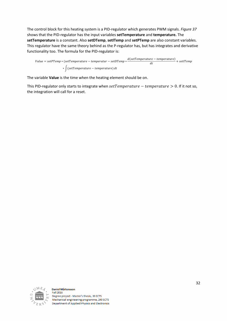
To create a control system for temperature of the heat exchanger, Simulink[ 16] has been used to
generate a P-regulator[ 8] in form of blocks which generate output PWM signals. This regulator
measures the error in temperature between the variables setTemperatureCooler and
temperatureColer. The error being amplified by a constant variable setPTempCooling. The
setTemperatureCooler is a constant.
The formula for the P-regulator is:
𝑉𝑎𝑙𝑢𝑒 = 𝑠𝑒𝑡𝑃𝑇𝑒𝑚𝑝𝐶𝑜𝑜𝑙𝑖𝑛𝑔 ∗ (𝑠𝑒𝑡𝑇𝑒𝑚𝑝𝑒𝑟𝑎𝑡𝑢𝑟𝑒𝐶𝑜𝑜𝑙𝑒𝑟 − 𝑡𝑒𝑚𝑝𝑒𝑟𝑎𝑡𝑢𝑟𝑒𝐶𝑜𝑜𝑙𝑒𝑟)
If the Value is above 0 the valve in is opening. If the Value is below 0, the valve is closing. The
variable Value holding how much time a relay, and which one, should be active.
All those blocks has been generated to PLC-code Structure Text[ 9] by Simulink toolbox package
Simulink PLC Coder. Figure 32 shows the block setup.
25
Figure 32: P-regulator in Simulink

26
5.2.3 The drain system To create a control system so the brewing machine can hold the wort level in malt bucket while
draining out wort, a drain system needs to be applied. This systems in works very similar to the
system above, because it’s a P-regulator which generates PWM signals. The variables setPvolume,
setPFlow, setOutFlow are constant variables. The setOutFlow is a variable to telling this P-regulator
to aim for a specific outflow. The setPvolume and setPFlow are only an amplifier constants.
The variables outFlowWater and outFlowMalt are variables which includes the flow rate from the
water bucket and the flow rate from the malt bucket.
The only which differs between this P-regulator and P-regulator above is that this is a multivariable
control system. The output of this system describes which ball valve and how long time it should be
opening or closing.
All those blocks have been generated to PLC-code Structure Text by Simulink toolbox package
Simulink PLC Coder. Figure 33 shows the block setup.
This multivariable control system controls a nonlinear model. To confirm that this multivariable
control system have the ability to control a nonlinear model, algorithm in MATLAB[ 17] code has
been applied. The algorithm describes Bernoulli’s principle[ 18] and simulates two system based on
Bernoulli’s principle. Those two system are the malt bucket and the water bucket. Water streaming
from the water bucket into the malt bucket, and wort streaming out from the malt bucket into the
boiler bucket. The control systems goal is to hold the wort level in the malt bucket, while the outflow
from the malt bucket is constant. To control the flow cross section area in the malt and water bucket
are controlled, increase or decrease the levels depending what flow rate out from the malt bucket
and what the malt bucket wort level is.

27
The MALTAB code calculates the area AreaBallValve as a function of the ball valve with respect on x. Thus x is the angle in degrees between 0 and 90. syms x
% hole ball valve radius in meter r = 0.0075;
% Two times the half circle
y = 2*sqrt(r^2 - x^2);
% Integrate y with respect on x AreaBallValve = int(y, x)
This MALTAB code shows the whichle simulation of two systems of Bernoulli’s principle. % Ball Valve area AreaBallValve m^2 function 0 <= x <= 0.0075 m a = @(x)
2*((4150517416584649*asin((8589934592*4150517416584649^(1/2)*x)/41505174165
84649))/73786976294838206464 + x*(4150517416584649/73786976294838206464 -
x^2)^(1/2));
Figure 33: Multivariable P-regulator system

28
% Start values p2 = @(x) x*1/90*0.0075; p1 = @(x) x*1/90*0.0075;
% Bucket area A = 0.2^2*pi;
% Begin position valves pos2 = 90; pos1 = 90;
% Start position level h2 = 1.1; h1 = 3;
% Gravity g = 9.82;
% Seconds to add in a vector t = 0; x = 0; % Start position level vector level2 = 0; level1 = 0;
% Set flow value out Qset = 0.001/60; % liter/s while(h2 > 0 && h1 > 0)
% Water bucket BallvalveArea2 = a(p2(pos2)); outFlowWater = BallvalveArea2*sqrt(2*g*h2); deltaV2dt = outFlowWater; h2 = h2 - outFlowWater/A; if(h2 < 0) h2 = 0; end level2 = [level2 h2]
% Malt bucket BallvalveArea1 = a(p1(pos1)); outFlowMalt = BallvalveArea1*sqrt(2*g*h1); deltaV1dt = outFlowWater - outFlowMalt; h1 = h1 - outFlowMalt/A + outFlowWater/A; if(h1 < 0) h1 = 0; end level1 = [level1 h1];
% P-regulator for valve above setPvolume = 160000; % Amplifier pos2 = -deltaV1dt*setPvolume; if(pos2 < 0) pos2 = 0; % Close valve above completely! elseif(pos2 > 90) pos2 = 90; % Open valve above completely! end
% P-regulator for valve below setPflow = 700000; % Amplifier

29
pos1 = (Qset - outFlowMalt)*setPflow; if(pos1 < 0) pos1 = 0; % Close valve below completely! elseif(pos1 > 90) pos1 = 90; % Open valve below completely! end
% Add seconds to vector every loop x = [x t]; t = t + 1;
end
% Plot the results figure(1) plot(x, level1) hold on title('Bucket below') xlabel('Time [s]') ylabel('Level [m]') figure(2) plot(x, level2) hold on title('Bucket above') xlabel('Time [s]') ylabel('Level [m]')
Figure 34 shows a time plot of the wort level in the lower bucket– the malt bucket, and the upper
bucket– the water bucket. The levels units are in meters. This plot shows that the principle of the
block setup of multivariable P-regulator are working.
Figure 34: Wort level in the buckets by simulating with multi P-regulators
5.2.4 The heating system To create a temperature control system for the water bucket and malt bucket, still again, Simulink
has been used to create a block algorithm which later is generated into PLC code by Simulink PLC
Coder. This temperature control system is using solid relays (SSR)ISBN: 6130204957

30
[ 19] to handle high voltage. The voltage and current are controlled ON or OFF by the SSR’s. When
the SSR’s are ON, the boiler- malt- and water bucket getting hotter because inside those buckets,
there is a heating element. Notice that only U1, U2, U9 SSR relays are for AC and the rest are DC. The
SSR relays for DC are for the drain system. The reason why SSR’s are being used, it’s because the
input of the SSR’s are PWM signals from the PLC. A regular mechanical relay has an ON/OFF state
limit while an SSR has no mechanics included. That means that the mechanical relay can only be used
for a shorter while due to fatigue. The SSR relay has a higher fatigue limit. Figure 35 shows the wiring
diagram for the SSR relays.
Figure 35: The wiring diagram of SSR-relays

31
To distribute the heat in malt bucket and water bucket, the system needs to have a whisk to create a
circulation so the heat can be disturbed all over the bucket. Figure 36 shows a combination of a shift
register, Darlington array and a voltage regulator[ 20] (7805) which runs the mechanical relay. Those
together control the mechanical arrays and the mechanical arrays RL5 and RL1 control motors which
rotates the whisks. Also RL2 and RL3 control the black recirculating pumps. Relay RL4 controls the
valve under boiler bucket if it should be open or not.
Figure 36: The mechanical relay system
32
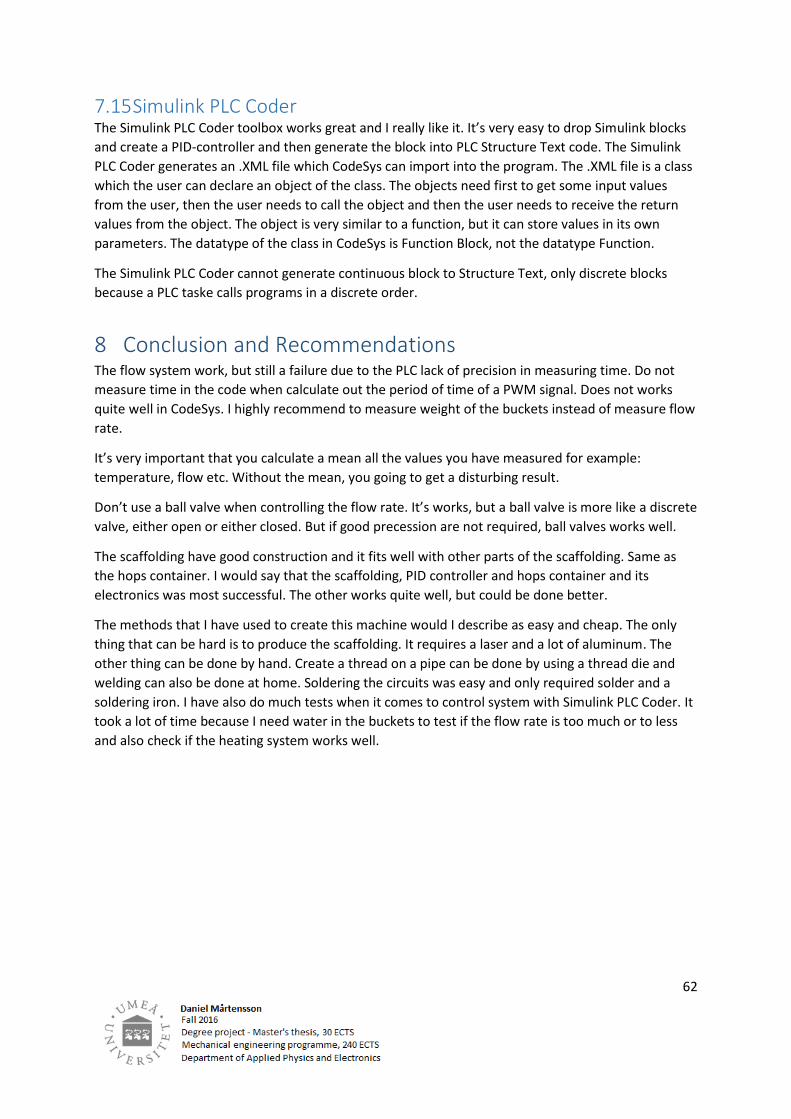
The control block for this heating system is a PID-regulator which generates PWM signals. Figure 37
shows that the PID-regulator has the input variables setTemperature and temperature. The
setTemperature is a constant. Also setDTemp, setITemp and setPTemp are also constant variables.
This regulator have the same theory behind as the P-regulator has, but has integrates and derivative
functionality too. The formula for the PID-regulator is:
𝑉𝑎𝑙𝑢𝑒 = 𝑠𝑒𝑡𝑃𝑇𝑒𝑚𝑝 ∗ (𝑠𝑒𝑡𝑇𝑒𝑚𝑝𝑒𝑟𝑎𝑡𝑢𝑟𝑒 − 𝑡𝑒𝑚𝑝𝑒𝑟𝑎𝑡𝑢𝑟 − 𝑠𝑒𝑡𝐷𝑇𝑒𝑚𝑝 ∗𝑑(𝑠𝑒𝑡𝑇𝑒𝑚𝑝𝑒𝑟𝑎𝑡𝑢𝑟𝑒 − 𝑡𝑒𝑚𝑝𝑒𝑟𝑎𝑡𝑢𝑟𝑒)
𝑑𝑡+ 𝑠𝑒𝑡𝐼𝑇𝑒𝑚𝑝
∗ ∫(𝑠𝑒𝑡𝑇𝑒𝑚𝑝𝑒𝑟𝑎𝑡𝑢𝑟𝑒 − 𝑡𝑒𝑚𝑝𝑒𝑟𝑎𝑡𝑢𝑟𝑒) 𝑑𝑡
The variable Value is the time when the heating element should be on.
This PID-regulator only starts to integrate when 𝑠𝑒𝑡𝑇𝑒𝑚𝑝𝑒𝑟𝑎𝑡𝑢𝑟𝑒 − 𝑡𝑒𝑚𝑝𝑒𝑟𝑎𝑡𝑢𝑟𝑒 > 0. If it not so,
the integration will call for a reset.

33
Figure 37: The heating system’s PID-regulator

34
5.2.5 The sensors locations Here are the temperature sensors locations. Figure 38 shows the temperature sensors locations for
the heat exchangers outlet and inlet. Also shows a temperature sensors on the upper bucket too –
the boiler bucket. The locations are marked with a blue arrow.
Figure 39 shows temperature sensors for malt bucket and water bucket. They are marked with
arrows. The round blue ring shows the location for the flow sensors.
Figure 38: Temperature location for heat exchanger and boiler bucket
Figure 39: Temperature sensor for water bucket(upper) and malt bucket(lower)

35
5.2.6 The PLC task and run time order Now when all principles are described above, it’s time to show principles of how the PLC’s tasks
should work. Also the run time work flow will be described too.
As the brewing process are told from the heading “The fundamental methods of brewing“, this
brewing machine needs a lot of different PLC tasks which run in the background so the main PLC
tasks can work proper.
A PLC are called main program to call different tasks, and the PLC need to make sure that sub-tasks
are calling too. Those sub-tasks make sure that the PLC has all values they need to control the ball
valves and the heating elements.
Table 3 shows a task list which counting necessary operations which can be viewed as principles for
automatic brewing with a PLC. The tasks cycle time are mentioned but that’s only an approximation.
Table 3: The tasks
Table 4 shows a principle of workflow sequence how the PLC system should work to automate the
brewing process.
Table 4: The work flow
Task number call Task Task cycle time Task mission
1 Main Normal Main work flow
2 Heating Normal The heating control system
3 HeatingRead Fast Read temperature
4 Flow Fast The flow control system
5 FlowRead Very fast Read the flow rate
6 Hops Normal The hops container system
7 Cool Normal The cooler system
8 Time Normal The time count system
9 GUI Normal Graphical control panel
Nr Operation description
0 Waiting for the user to start the system.
1 Motor 1 starts and heating system for malt bucket starting
2 When the temperature of the malt bucket is above the start value -> Start counting time
3 After a while, the heating system and motor 2 is going to start for the water bucket.
4 When timer has reached its time limit, motor 1, 2 and both heating system shut down.
5 The recirculating pump started for malt bucket. Runs only two minutes.
6 Drain system is starting. Draining from malt bucket to boiler bucket.
7 When the level of the boiler bucket is filled up to the limit. Start the heating process.
8 When the medium inside the boiler bucket start to boil -> Start counting time.
9 Minutes after minutes, hops drops down from the hops container, into the boiler bucket.
10 When the boiler time has run out -> Shut down the heating system and hops system.
11 Start the cooling system and cool down the medium while it collects in the cooling bucket.
12 When the machine is turned off -> cooling system shut down and go to step 0.

36
When it comes to task number nine, the control panel. The design needs to show temperature, time,
set of hops etc. It’s also necessary to have a start button inside the control panel. Figure 40 shows
basic setup of how a control panel could look like for a brewing machine. The control panel focus on
malt bucket, water bucket, boiler bucket and the heat exchanger – everything that’s needed.
Figure 40: Example of a control panel – In offline mode

37
6 Results In this section, pictures will only be given. A discussion will explain the results.
6.1 The scaffolding walkthrough Figure 41 shows tree pictures of the scaffolding at the moment when the brewery’s setup is
complete.
For more pictures at the complete scaffolding, have a look at the attached pictures in appendix A, B,
C, D and E. This walkthrough will show the bottom to the top of the brewing machine and explaining
what’s included inside the picture. Figure 42 shows the cooler valve with a temperature sensor.
Figure 42: The cooler valve
Figure 41: The complete scaffolding

38
Figure 43 shows the bottom bucket which collects wort that has been cooled down.
Figure 43: The bottom
Figure 44 shows the heat exchangers outlet and inlet. The outlet is the upper hose.
Figure 44: Outlet and inlet

39
Figure 45 shows the heat exchanger and its pipes.
Figure 45: The heat exchanger
Figure 46 shows the cooler bucket which going to contain cold water.
Figure 46: The cooler bucket

40
Figure 47 shows the temperature sensor for the inlet at the heat exchanger.
Figure 48 shows the water pump which transfer cold water into the heat exchanger.
Figure 48: The water pump
Figure 47: Temperature sensor

41
Figure 49 shows inside the boiler bucket.
Figure 50 shows boiler bucket’s ball valve.
Figure 50: Ball valve for boiler bucket
Figure 49: Inside the boiler bucket

42
Figure 51 shows the hops container.
Figure 51: The hops container

43
Figure 52 shows how the temperature is attached. It’s rubber which protect the temperature sensor.
The sensor is placed inside a small pipe which also are attached at the bucket. At this picture, the
pipe is attached onto the boiler bucket.
Figure 52: Temperature sensor

44
Figure 53 shows a closer look at the servos. When the servo shaft rotates, the plate is falling down.
Figure 54 shows servos location on the hops container.
Figure 54: The servos
Figure 53: A closer look at the servo

45
Figure 55 shows another close look at the plates which are falling down when the servo rotates.
Figure 55: The plate
Figure 56 shows the recirculating pump which recirculates the wort.
Figure 56: The recirculating pump

46
Figure 57 shows a T-pipe and a ball valve for the malt bucket. The hose on the T-pipe are going the
recirculating pump.
Figure 57: The valve and T-pipe for the malt bucket
Figure 58 shows the outlet for the recirculation pump. The outlet will contain wort and it will be
transferred back into the malt bucket.
Figure 58: Recirculation pump's outlet

47
Figure 59 shows the motorized whisk inside the malt bucket.
Figure 60 shows the heating element and the temperature sensor for the malt bucket.
Figure 60: The heating element and the temperature sensor
Figure 59: The motorized whisk

48
Figure 61 shows what’s inside the malt bucket. Here the heating element can be viewed.
Figure 61: Inside the malt bucket
Figure 62 shows the water bucket’s heating element and temperature sensor.
Figure 62: The heating element

49
Figure 63 shows the water bucket’s ball valve and flow sensor.
Figure 63: The water bucket’s valve and flow sensor
Figure 64 shows what’s inside in the water bucket. A heating element, pipe for the temperature
sensor, and a filter at the centrum of the bucket, which filtrate the water.
Figure 64: Inside in the water bucket

50
Figure 65 shows the top of the bucket. Here the motor mounts can be shown how it’s attached onto
the scaffolding.
Figure 66 shows the water bucket’s motor mounts.
Figure 66: The motor bearer
Figure 65: The top

51
6.2 The PLC control box Here the result of the PLC control box will be presented. The function of the parts will be explained.
Figure 67 and Figure 68 show the complete control box. This control box contains mechanical and
solid states relay, 555 timer and the Raspberry Pi B+ which works as the PLC. This is the box which
control the brewing machine. Control the temperature after the temperature set point and rotate
the servos. This control box need 230 Volt AC and requires maximum 3A current to run. The PLC itself
requires about 0.2-0.3A current to run.
This control box contains following:
7. 6 SSR DC - DC relays
8. 3 SSR DC - AC relays
9. 1 Transformer 230 Volt to 5 volt
10. 1 555 timer system
11. 6 Mechanical relays
12. 2 Shift registers
13. 2 Darlington transistor arrays
14. 1 Analog to digital converter
15. 1 IC-relay
16. Raspberry Pi B+
17. 16 Outputs (5, 12 and 230 volt)
18. 7 Inputs (3.3 volt)
Figure 67: Another view

52
Figure 68: The control box
Figure 69 shows the control box on the top side. The inputs can be viewed to the left of the figure.
The red and black stero plugs are used as connectors.
Figure 69: The inputs to the left

53
Figure 70 shows the outputs from the control box.
Figure 70: The outputs

54
Figure 71 shows the inside of the control board.
Figure 71: Zoomed in view on the control board
Figure 72 shows the 555 timer system. That system can control the servos position based on the 555
circuit setup to generate PWM pulses. Figure 72 also show the voltage regulator which transform 12
Volt to five Volt.
Figure 72: The 555 timer system

55
Figure 73 shows another part of the control board. Here can the shift register(right), Darlington
transistor array(left) and ADC(up) be viewed. The ADC’s mission is to read the temperature sensors.
The shift register works together with the Darlington array to create an integrated circuit relay. The
shift register and Darlington array is only included inside this control box because the lack of I/O-pins
from Raspberry Pi B+.
Figure 73: Closer look

56
Figure 74 shows the SSR DC-DC relays. Those relays control the blue ball valves. Two SSR relays per
each ball valve, one for closing and one for opening.
Figure 74: SSR relays DC – DC
Figure 75 shows the voltage port for the control box.
Figure 75: Voltage port 230 Volt

57
Figure 76 shows the SSR DC-AC relay are used for controlling. Those relays are for control the heating
elements for malt, water and boiler bucket.
Figure 76: SSR relays DC-AC
Figure 77 shows the Ethernet connection for the PLC.
Figure 77: Ethernet connection

58
Figure 78 shows that Ethernet cable from the PLC goes to a DCHP-server. Though this server, it’s
possible to communicate between a computer over the internet to the PLC.
Figure 78: The DCHP-server
Figure 79 shows the control panel for the PLC. The control panel is used to control, temperature,
time limits, view the temperature, set time when different sets of hops should be added into the
boiler bucket, presents how much volume the boiler bucket has and determine the set values for
temperature a regulator should aim for. And also, a start button.
Figure 79: The control panel

59
7 Reflections In this section, a reflection which explaining why it did happen.
7.1 Reflections about the mechanical design This project work out really well. I’m very proud of the mechanical construction and the parts fit like
a glove. The construction scaffolding is very symmetric, but one thing to think at is the precision. To
good precision will result that it will be difficult to assembly the scaffolding. So I recommend at least
0.5 mm in tolerance. No more, no less. This scaffolding is very stable and I can even stand on it.
7.2 The cooler system In this topic, I’m going to discuss the P-regulator which controls the last ball valve before wort end up
into the bucket at the bottom. I would like to say that it’s possible to regulate a ball valve with a P-
regulator, but it’s difficult because of the dead time which are caused by inertia and friction. The
regulator only required to give a 100 mS high pulse for open the ball valve. Then the ball inside the
ball valve has turn about 3-4 degrades. So I have made so the P-regulator only gives about 5-10 mS in
pulses for opening or closing the valve. I recommend to use a ball valve if you going to choose
between full opening and full closed. But it works.
7.3 The heat exchanger The heat exchanger was a success. It’ didn’t leak anything and all the pipes slopes about 1-2
degrades. But the problem with the heat exchanger it’s that it will not be a good tasteful beer with
that heat exchanger. I have mix between cooper and stainless steel, and soldering with silver. That’s
is not a good combination. So I have to figure out a better way to cool down wort before I will add in
yeast. I have thought about to not using a heat exchanger. Just collect the wort in the bucket, and
place the bucket into a fridge. But anyway, I can still use the heat exchanger in other cases.
7.4 The hops container The hops container was also another success. Actually, I will use this in this project because
everything works. The only bad think with this container it’s made in aluminum. But as long it stays
dry, it will not be any oxidation. The container gives set of hops at different times and the servos are
very stable, even that the servos and cables are not EMC-protected.
7.5 The heating system To create the heating system, I have to use an ADC to communicate to the PLC. I had to read
datasheets about this ADC and create PLC code in Structure Text language. It was not a big job, but
when it comes down to two additional shift registers, I have to figure out how to extend the PLC code
so I can communicate with those too. I have used SPI-communication because it was very easy to
construct. I recommend SPI-communication with PLC. It’s very important that the PLC can create a
mean through interpolation the temperature values, or else, the values will differ about ±2
degrades. In this case, I have my temperature values in Celsius.

60
7.6 The drain system The drain system was a failure, not because of the code or the sensors, but because of CodeSys itself.
CodeSys have a precision of 1 mS for calculate time in the code. That’s very bad. I have flow sensors
which output are PWM signals. When I going to calculate out the period of those PWM pulses. The
PLC code resets a counting clock when the PLC gets a high pulse and waits until it get a low pulse, and
stop the clock when the PLC gets another high pulse. Then the period of the PWM signal can be
measured, and minimum measurement are 1 mS. So it would be better to create a module which can
measure PWM signals a little bit faster and generate them through a SPI-communication. The values
from my flow sensors differ ±0.5 and that very much if you want to have 1 liter/min in flow rate. The
type of the flow sensors is a rotating measuring gears flow sensor. Let’s say that the flow system
works, but it could be done much better by measure the weight of the buckets instead.
7.7 The motorized whisk The motorized whisk was very easy to construct. I haven’t have problems with those. One problem is
that the whisk are galvanized. So I cannot use them to brew beer. That’s the only problem. But I’m
aiming to use the pumps only. I remove the water pump from the heat exchanger, and place that
pump with the water bucket, just the same as the malt bucket – recirculation. That will distribute the
heat in the malt bucket and the water bucket.
7.8 The locations of the temperature sensors The locations of the temperature sensors works really well. But now when I have so good distribution
of the heat inside the buckets. I think that I would have to move those sensors to locations away
from the heating elements. Also I want to say that creating a pipe that a sensor fits into, was a really
smart way to attach sensors to the brewing machine.
7.9 EMC disturbing Even I have cables everywhere, I have not feel any issues with the EMC. The only thing I have done
to minimize EMC effect was to twist the cables to reduce the influence of present magnetic
fields. I have not experienced any EMC issues with the design.
7.10 The control box The control box is made of transparent acrylic plates. The wiring is not a charm but it works. One
problem I have to fix is that is not possible to control the SSR relays with 3.3 voltage from Raspberry
PI’s I/O-pins. Therefor I have been using an integrated circuit relay which gives 5.0 voltage, but is
controlled by 3.3 voltage. I just want to say that 3.3 voltage is a very low voltage to turn a relay,
mechanical or solid state, ON-mode. So I recommend only to use 3.3 voltage when communicating
with other types of integrated circuit.

61
7.11 PID controlling inside this PLC Creating a PID regulator with PLC code works well. The only problem is the D-part. Because if the
values differ a lot and are not stable, you will have a problem. Integrating works well and the
amplifying factor(P-regulator) works as well too. I would say that a PI regulator is enough if you got
bad values which differ a lot.
7.12 Social and Ethical aspects of the work Make sure what material are being used. Avoid aluminum in water. The heat exchanger for example
works, but it is not going to fit as in the process of cooler to cool down wort. The heat exchanger
contains copper and rubber which can give allergic reactions. Think of that. And also, there is a need
of replacing the whisk to whisks are made of stainless steel, if I’m going to use them. But I have
thoughts about having another recirculation pump for the water bucket.
The main EMC disturbing is at 50 Hz frequency and that has not affected on my brewing machine. I’m
not saying that you should forget the EMC, but have those thoughts in back of your head when you
do cabling on soldering PCB cards.
I would say that this system, CodeSys with Raspberry Pi, is more for hobby and good for education
due to that inexpensive tools and components have been used and can be used in education. For
hobby, it works just as a commercial PLC, whiteout the industrial protection. Combined CodeSys and
Raspberry Pi with Simulink PLC Coder and it will good possibilities to create high technological control
systems which are far more technical that regular commercial PLCs.
7.13 Advantages by internet connection There are good advantages to have internet connection to the PLC. First of all it’s very easy to
connect and best of all, it’s possible to control the PLC over the Internet. I does not matter where you
are. Just connect the PLC to the DHCP server and then you can be miles away, and still have the
ability to program the PLC and see what its results. The only thing you need to do is to set a lock on
the PLC so no one else can reach it and chance the program inside the PLC. To do that, an IP lock
need to be activated in the PLC. It’s more like a password.
7.14 Advantages by automation Automation is the future. For a long time ago, almost everything was done by hand. Modern
computers can controls most of all systems. Computers can run that thought several methods such
as machine learning, controlling and logging data. Without automation, people will do the work, but
it will not be fast as computers, not exactly same precision as computer and muscles and brains can
feel pain, machines do not feel pain and have no feelings.
Replacing unnecessary hard monotone work with machines will results that the human being can live
longer due to fatigue in muscles and health.
62
7.15 Simulink PLC Coder The Simulink PLC Coder toolbox works great and I really like it. It’s very easy to drop Simulink blocks
and create a PID-controller and then generate the block into PLC Structure Text code. The Simulink
PLC Coder generates an .XML file which CodeSys can import into the program. The .XML file is a class
which the user can declare an object of the class. The objects need first to get some input values
from the user, then the user needs to call the object and then the user needs to receive the return
values from the object. The object is very similar to a function, but it can store values in its own
parameters. The datatype of the class in CodeSys is Function Block, not the datatype Function.
The Simulink PLC Coder cannot generate continuous block to Structure Text, only discrete blocks
because a PLC taske calls programs in a discrete order.
8 Conclusion and Recommendations The flow system work, but still a failure due to the PLC lack of precision in measuring time. Do not
measure time in the code when calculate out the period of time of a PWM signal. Does not works
quite well in CodeSys. I highly recommend to measure weight of the buckets instead of measure flow
rate.
It’s very important that you calculate a mean all the values you have measured for example:
temperature, flow etc. Without the mean, you going to get a disturbing result.
Don’t use a ball valve when controlling the flow rate. It’s works, but a ball valve is more like a discrete
valve, either open or either closed. But if good precession are not required, ball valves works well.
The scaffolding have good construction and it fits well with other parts of the scaffolding. Same as
the hops container. I would say that the scaffolding, PID controller and hops container and its
electronics was most successful. The other works quite well, but could be done better.
The methods that I have used to create this machine would I describe as easy and cheap. The only
thing that can be hard is to produce the scaffolding. It requires a laser and a lot of aluminum. The
other thing can be done by hand. Create a thread on a pipe can be done by using a thread die and
welding can also be done at home. Soldering the circuits was easy and only required solder and a
soldering iron. I have also do much tests when it comes to control system with Simulink PLC Coder. It
took a lot of time because I need water in the buckets to test if the flow rate is too much or to less
and also check if the heating system works well.

63
9 References [ 1] Dag H. Hansen, “Programmable Logic Controllers: A Practical Approach to IEC 61131-3 using
CodeSys”, Wiley, 2015, ISBN: 978-1-118-94924-5
[ 2] W. Bolton, “Programmable Logic Controllers” Newnes, 2015, ISBN: 9780128029299
[ 3] Eben Upton, Gareth Halfacree, “Raspberry Pi User Guide”, Wiley, 2016, ISBN: 9781119264361
[ 4] Jeremy Blum, “Exploring Arduino: Tools and Techniques for Engineering Wizardry”, Wiley, 2013,
ISBN: 9781118549360
[ 5] Han-Way Huang, “The Atmel AVR Microcontroller”, Delmar Cengage Learning, 2013, ISBN:
9781133607298
[ 6] Michael Weeks, “Arduino controlled brewing”, Georgia State University U.S.A , IEEE, 25 June
2015, INSPEC Accession Number: 15240653
[ 7] Kurt Staudter, Adam Krakowski, “Vermont Beer: History of a Brewing Revolution”, The History
Press, 2014, ISBN: 9781626194823
[ 8] Jens Graf , “Pid Control: Ziegler-Nichols Tuning”, CreateSpace, 2013, ISBN: 9781494246914
[ 9] Michael Tiegelkamp, “IEC 61131-3, Karl-Heinz John, Springer, 2010, ISBN: 9783642120145
[ 10] "Umeå University homepage", Sweden, Last accessed January 1, 2017, http://www.umu.se
[ 11] “LM 555 timer”, Texas Instruments, Last accessed January 1, 2017, http://www.ti.com
[ 12] "74HC595 Shift register IC", NPX Semiconductors, Last accessed January 1, 2017,
http://ww.npx.com
[ 13] "Serial Peripheral Interface Bus (SPI)”, Wikipedia, Last accessed January 1, 2017,
http://en.www.wikipedia.org/wiki/Serial_Peripheral_Interface_Bus
[ 14] "ULN2003 Darlington transistor array", Texas Instruments, Last accessed January 1, 2017,
http://www.ti.com
[ 15] ”MPC3008 Analog to digital converter”, Microchip, Last accessed January 1, 2017,
http://www.microchip.com
[ 16] Luca Zamboni, “Getting Started With Simulink”, Packt Publishing Limited, 2013, ISBN:
9781782171386
[ 17] Amos Gilat, “MATLAB: An Introduction with Applications”, Wiley, 2014, ISBN: 9781118629864
[ 18] Frederic P. Miller, Agnes F. Vandome, John McBrewster, "Bernoulli’s principle”, Alphascript
Publishing, 2010, ISBN: 6130204957
[ 19] "Solid State relay DA-DA/DA-AC 25", Fotek, Last accessed January 1, 2017,
http://www.fotek.com
[ 20] ”LM7805 Voltage regulator”, Texas Instruments, Last accessed January 1, 2017,
http://www.ti.com

64
10 Appendix 10.1 A

65
10.2 B

66
10.3 C
67
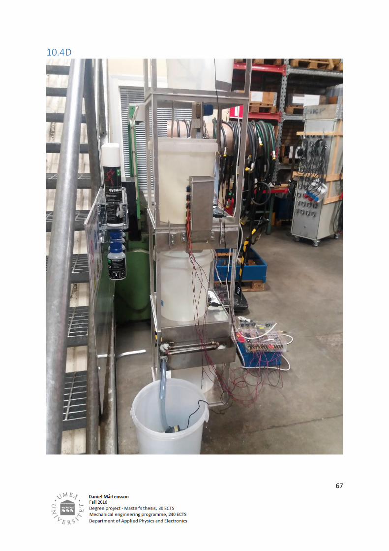
10.4 D

68
10.5 E