Embed Size (px)
Citation preview

Konkuk University
Principles & Applications ofElectrical Engineering
Ch. 3 Resistive Network Analysis- illustrate fundamental technique for resistive
circuits analysis
Spring, 2018
Rizzoni, 6th Ed.

2
Contents¢ Learning objectives
� Compute the solution of circuits containing linear resistors and independent and dependent sources by using node analysis.uSections 3.2 and 3.4.
� Compute the solution of circuits containing linear resistors and independent/dependent sources by using mesh analysis.uSections 3.3 and 3.4.
� Apply the principle of superposition to linear circuits containing independent sources.uSection 3.5.

3
� Compute Thévenin and Norton equivalent circuits for networks containing linear resistors and independent and dependent sources.uSection 3.6.
� Use equivalent-circuit ideas to compute the maximum power transfer between a source and a load.uSection 3.7.
� Use the concept of equivalent circuit to determine voltage, current, and power for nonlinear loads by using load-line analysis and analytical methods.uSection 3.8.

4
¢ Network analysis� determining each of the unknown branch currents and
node voltages.
??==
y
x
vi
5
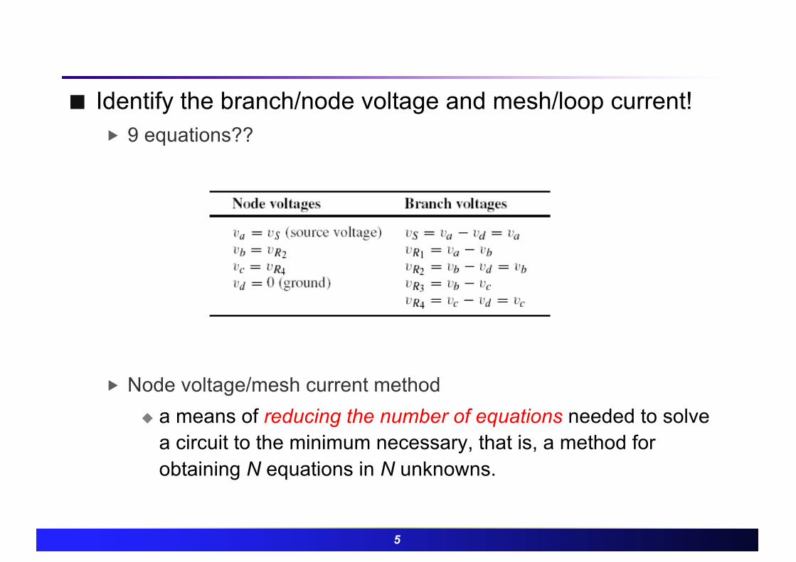
¢ Identify the branch/node voltage and mesh/loop current!� 9 equations??
� Node voltage/mesh current methodu a means of reducing the number of equations needed to solve
a circuit to the minimum necessary, that is, a method for obtaining N equations in N unknowns.

6
¢ Node voltage method (node analysis)� Is based on defining the voltage at each node as an
independent variable.� One of the nodes is selected as a reference node� How to solve ?
uSelect a reference node (usually ground)uDefine the remaining n-1 node voltages as the
independent/dependent variablesuApply KCL at each node labeled as an independent
variableuSolve the linear equations with reduced unknowns
7
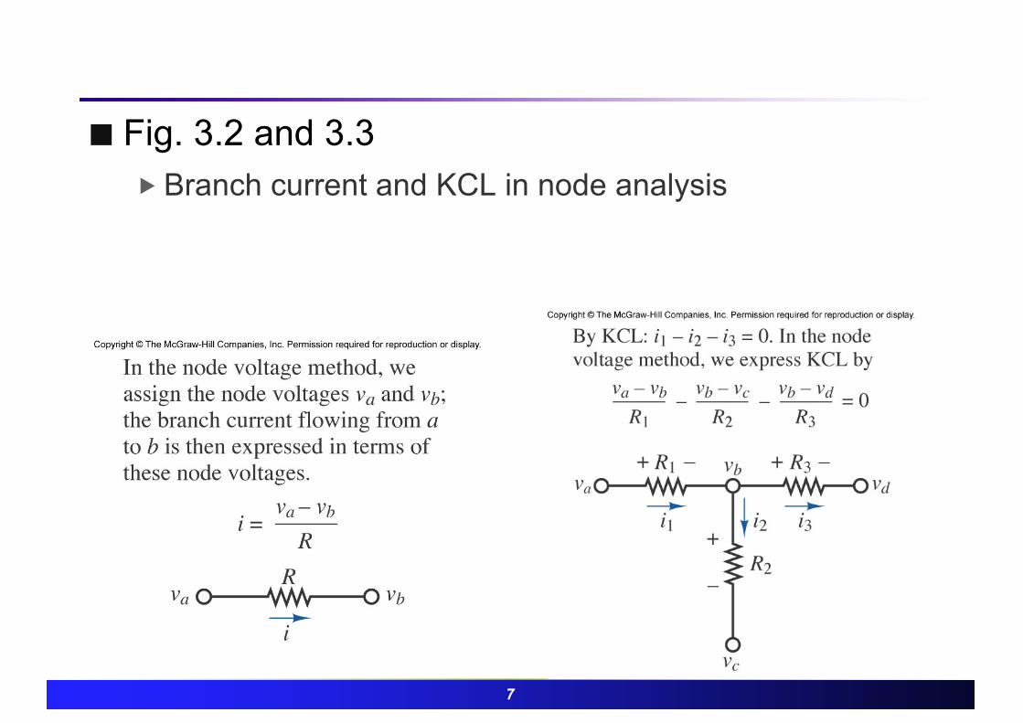
¢ Fig. 3.2 and 3.3� Branch current and KCL in node analysis
8
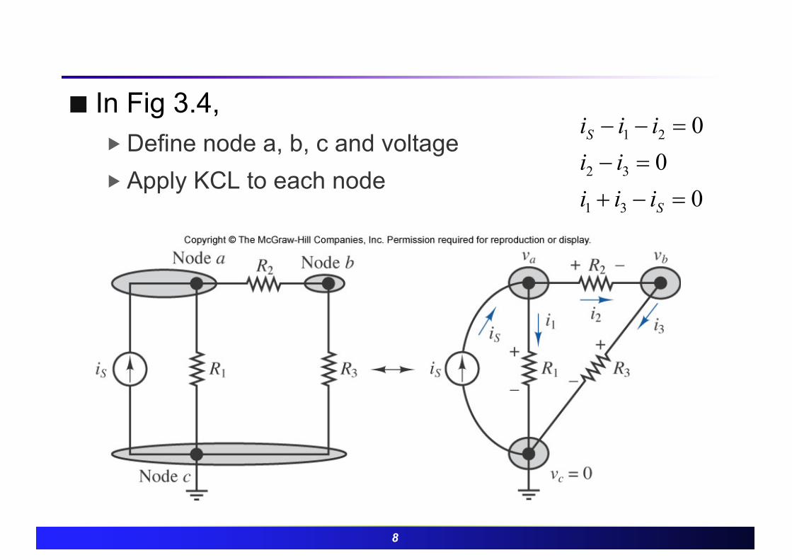
¢ In Fig 3.4, � Define node a, b, c and voltage� Apply KCL to each node
000
31
32
21
=-+=-
=--
S
S
iiiiiiii

9
¢ Example 3.2� Solve for node voltages� I1=10mA, I2=50mA, R1=1kohms, R2=2kohms,
R3=10kohms, R4=2kohms,

10
¢ Example 3.3� Solve for node voltages� Ia=1mA, Ib=2mA, R1=1kohms, R2=500ohms,
R3=2.2kohms, R4=4.7kohms,
11
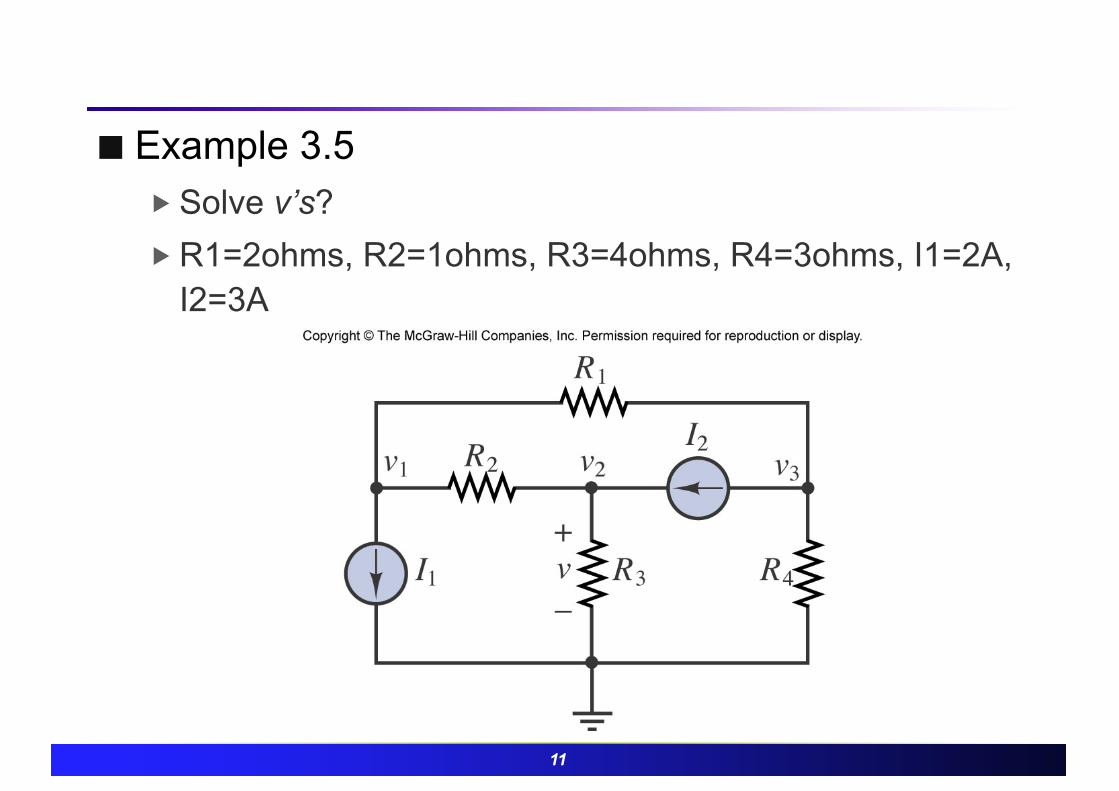
¢ Example 3.5� Solve v’s?� R1=2ohms, R2=1ohms, R3=4ohms, R4=3ohms, I1=2A,
I2=3A

12
¢ Node analysis with voltage source� Same methodology is applied (KCL is used)� Figure 3.10

13
¢ Example 3.6� Solve v’s?
14
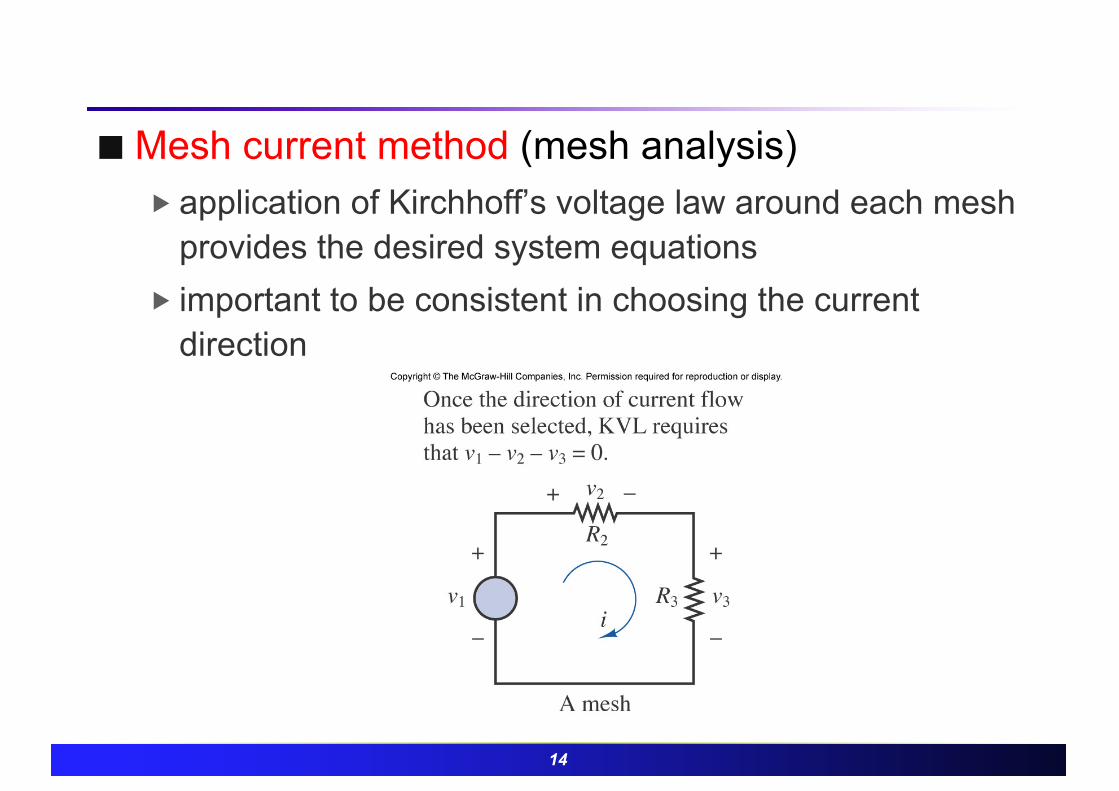
¢ Mesh current method (mesh analysis)� application of Kirchhoff’s voltage law around each mesh
provides the desired system equations� important to be consistent in choosing the current
direction
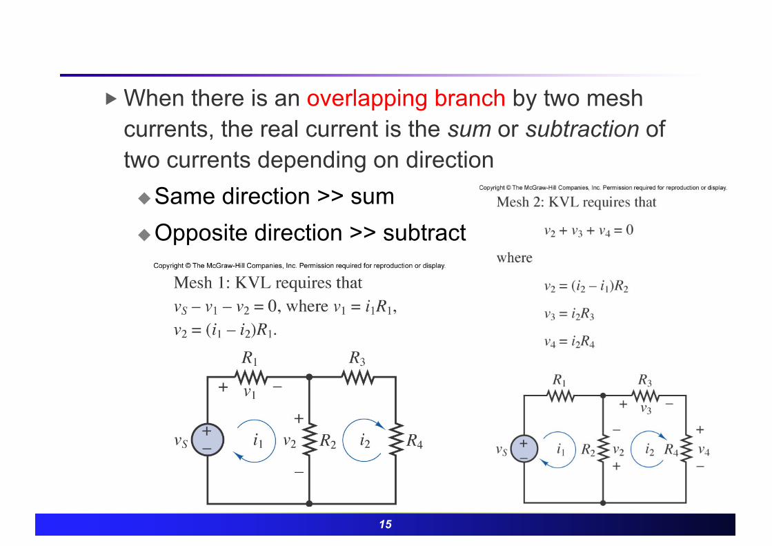
15
� When there is an overlapping branch by two mesh currents, the real current is the sum or subtraction of two currents depending on directionuSame direction >> sumuOpposite direction >> subtract

16
¢ Example 3.7� Solve
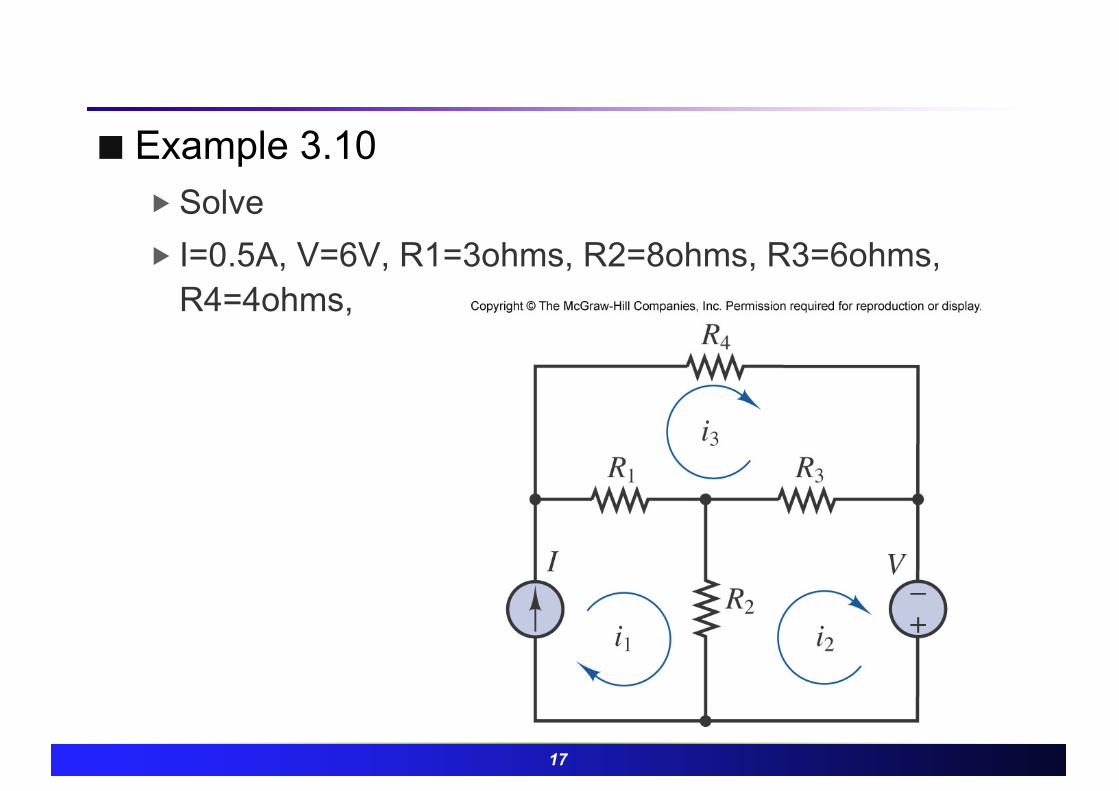
17
¢ Example 3.10� Solve� I=0.5A, V=6V, R1=3ohms, R2=8ohms, R3=6ohms,
R4=4ohms,

18
¢ Node and mesh analysis with controlled (dependent) sources� constraint equation can be substituted in the set of
equations obtained by the node and mesh analysis

19
� In the previous figure, calculate voltage at each nodeuOne constraint equation can be found

20
¢ Example 3.13� Determine the voltage gain, v2/v1?

21
3.5 Superposition¢ Principles of superposition
� Each source generates superposed current and voltage� In a linear circuit containing N sources, each branch
voltage and current is the sum of N voltages and currents, each of which may be computed by setting all but one source equal to zero and solving the circuit containing that single source.

22
¢ How to remove each source?

23
¢ Example 3.14� Solve� Vs=10V, Is=2A, R1=5ohms, R2=2ohms, R3=4ohms

24
¢ One-port networks� General and simple representation of circuit by source
and load.� develops techniques for computing equivalent
representations of linear networks. Such representations are useful in deriving some simple results for linear /nonlinear circuits.

25
¢ Thévenin theorem� When viewed from the load, any network composed of
ideal voltage and current sources, and of linear resistors, may be represented by an equivalent circuit consisting of an ideal voltage source in series with an equivalent resistance
26
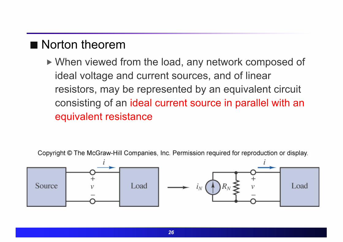
¢ Norton theorem� When viewed from the load, any network composed of
ideal voltage and current sources, and of linear resistors, may be represented by an equivalent circuit consisting of an ideal current source in parallel with an equivalent resistance

27
¢ How to compute ‘equivalent resistance’ of a one-port network?
1. Remove the load2. Zero all independent voltage and current sources.
� Current source as open� Voltage source as short
3. Compute the total resistance between load terminals, with the load removed. This resistance is equivalent to that which would be encountered by a current source connected to the circuit in place of the load.
� See p. 111

28
¢ Example 3.17

29
¢ The equivalent (Thévenin) source voltage � is equal to the open-circuit voltage present at the load
terminals (with the load removed).
¢ How to compute Thévenin voltage ?� 1. Remove the load, leaving the load terminals open-
circuited.� 2. Define the open-circuit voltage Voc across the open
load terminals.� 3. Apply any preferred method (e.g., node analysis) to
solve Voc � 4. The Thévenin voltage is Voc.

30
¢ Open circuit and Thévenin voltage

31
¢ Thevenin equivalent circuit� Simplify the circuit to represent the equivalent
resistance and voltage source seen from the load

32
¢ Example 3.20
33
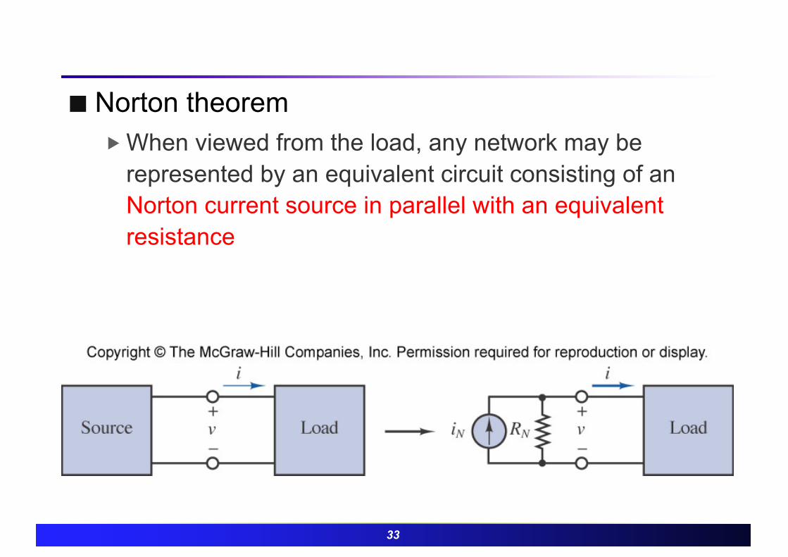
¢ Norton theorem� When viewed from the load, any network may be
represented by an equivalent circuit consisting of an Norton current source in parallel with an equivalent resistance
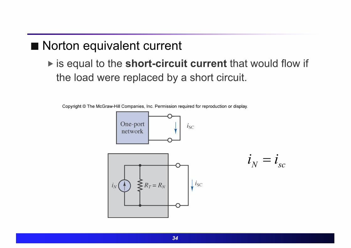
34
¢ Norton equivalent current � is equal to the short-circuit current that would flow if
the load were replaced by a short circuit.
scN ii =

35
¢ How to compute the Norton current?� 1. Replace the load with a short circuit.� 2. Define the short-circuit current to be the Norton
equivalent current, IN.� 3. Apply any preferred method (e.g., node analysis) to
solve for the current, Isc� 4. The Norton current is Isc

36
¢ Example 3.21� Norton current & equivalent circuit

37
¢ Source transformation� Norton and Thévenin theorems state that any one-port
network can be represented by a voltage source in series with a resistance, or by a current source in parallel with a resistance, and that either of these representations is equivalent to the original circuit
�Reciprocal transformation between themselves
38
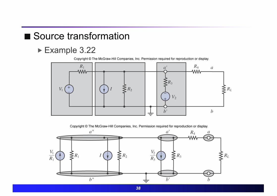
¢ Source transformation� Example 3.22

39
¢ Source transformation
0.005[ ] 0.5 0.005 0.5200[ ] 100 ||100 || 200 160
A = - + +W = +
40
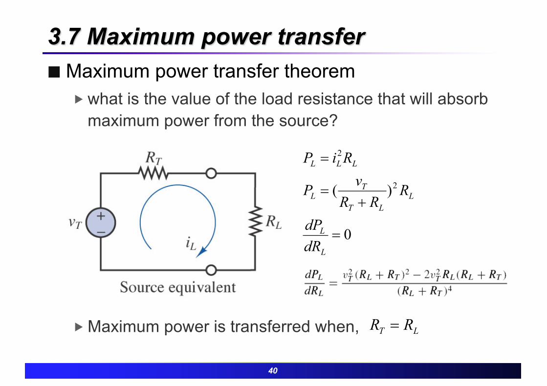
3.7 Maximum power transfer¢ Maximum power transfer theorem
� what is the value of the load resistance that will absorb maximum power from the source?
� Maximum power is transferred when, LT RR =
0
)( 2
2
=
+=
=
L
L
LLT
TL
LLL
dRdP
RRR
vP
RiP

41
� to transfer maximum power to a load, the equivalent source resistance and load resistance must be matched

42
¢ Loading effect of source� When practical source is connected, source loading
effect happens due to internal resistance.
43
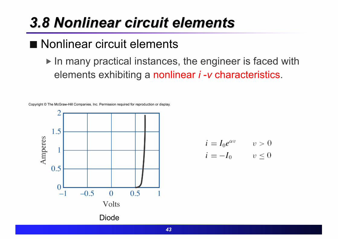
3.8 Nonlinear circuit elements¢ Nonlinear circuit elements
� In many practical instances, the engineer is faced with elements exhibiting a nonlinear i -v characteristics.
Diode
44
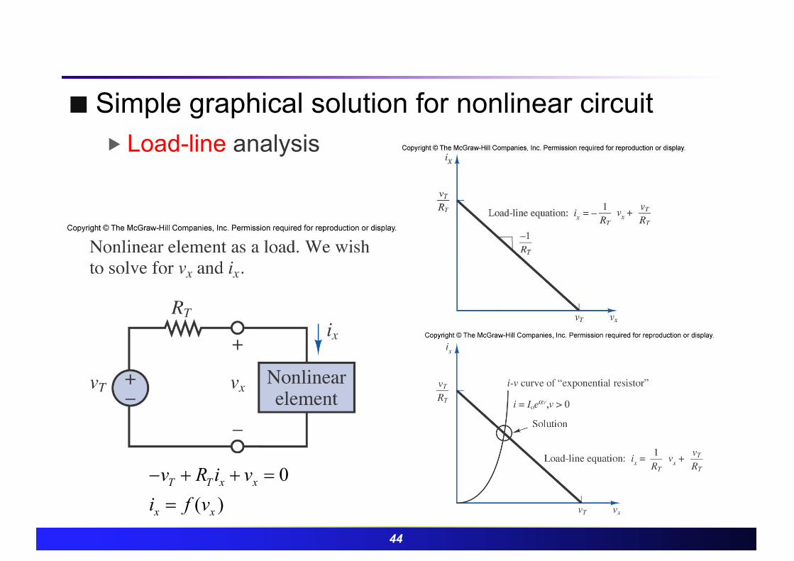
¢ Simple graphical solution for nonlinear circuit� Load-line analysis
0( )
T T x x
x x
v R i vi f v- + + =
=

45
¢ One advantage of circuit reduction� Simplify the circuit containing nonlinear element, then
apply load-line analysis method

46
Summary¢ Summary
� Node/Mesh analysis methodu Compute the solution of circuits containing linear resistors and
independent and dependent sources by using node/mesh analysis
u applicable to electric circuits containing nonlinear circuit elements
� Principle of superposition to linear circuits containing independent sources
u Generate separate mesh current/node voltage in each elementu Combine each current and voltage to produce resulting output
� Thévenin and Norton equivalent circuits for networks containing linear resistors and independent and dependent sources
u Simplified representation of the circuit network with equivalent source and resistance

47
Summary� Equivalent-circuit ideas to compute the maximum power transfer
between a source and a loadu Maximal point when load is equal to the equivalent source
resistance
� Equivalent circuit to determine voltage, current, and power for nonlinear loads by using load-line analysis and analytical methods
u Graphical interpretation to solve solution