Embed Size (px)
Citation preview
PRINCIPLES OF GPS
ByBy
Dana M. SommerDana M. Sommer

Why Use GPS?
Location - to determine a basic position.
Navigation – to get from one location to another.
Tracking – to monitor the movement of people and things.
Mapping – to create maps of the world.
Timing – to bring precise timing to the world.

What is GPS?

GPS solves the answer to one of man’s oldest and most critical question……
Where on Earth am I?

In the past, man often used the sun and stars for navigation, as well as landmarks such as rocks and trees.
These worked well at times but the problem is….
….the sun and stars cannot be seen when it’s cloudy and landmarks can often be confused with others, and even sometimes turn up missing.

It soon became very evident that there had to be a better solution to the problem of locating and obtaining an accurate and absolute position.

U.S. Dept of Defense (DoD)
In the early 1970’s, the DoD proposed a Global Positioning System (GPS) called NAVSTAR (NAVigation Satellite Timing And Ranging).
The first NAVSTAR satellite was launched by the U.S. Air Force in early 1978 for military use.
NAVSTAR was expanded for civilian use in the 1980’s.
In 1994, a full constellation of 24 satellites was achieved.

Foreign GPS Satellite Systems
Foreign GPS Satellite Systems Include:
Europe’s GALILEO - currently under development; Europe’s version of NAVSTAR; scheduled to be complete in 2008.
Europe’s EGNOS – (Euro Geostationary Navigation Overlay Service) – Europe’s version of WAAS.
Russia’s GLONASS – (Global Navigation Satellite System) – Russia’s version of NAVSTAR but not as reliable due to too many satellite failures.
Japan’s MSAS – Multi-Functional Satellite Augmentation System – Japan’s version of WAAS.
NAVSTAR GPS
The NAVSTAR GPS system is a $12 billion satellite radio-based navigation system that is made up of a network of 24 satellites placed in a very precise orbit to give a user a mathematically applied “triangulated” position.
Operated by the DoD, the NAVSTAR GPS system provides:
* Worldwide Three Dimensional Coverage of
the Earth (except at Poles)
* 24 Hour/365 Day Access
* Common Coordinate System (WGS84)
* Works in Any Type of Weather
* Free Access (no subscription fees or setup charges)
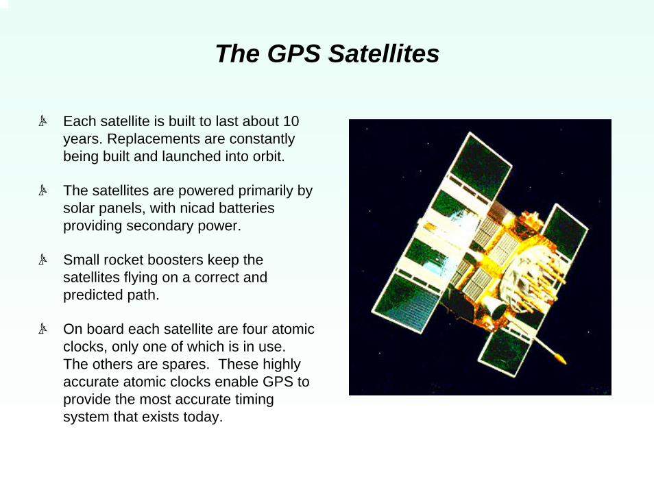
The GPS Satellites
c Each satellite is built to last about 10 years. Replacements are constantly being built and launched into orbit.
c The satellites are powered primarily by solar panels, with nicad batteries providing secondary power.
c Small rocket boosters keep the satellites flying on a correct and predicted path.
c On board each satellite are four atomic clocks, only one of which is in use. The others are spares. These highly accurate atomic clocks enable GPS to provide the most accurate timing system that exists today.

Components of a GPS System(NAVSTAR)
1. Space Segment1. Space Segment
2. User Segment2. User Segment
3. Control Segment3. Control Segment

GPS COMPONENTS
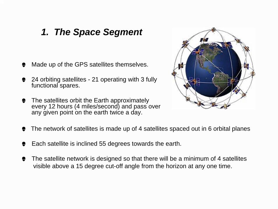
1. The Space Segment
Made up of the GPS satellites themselves.
24 orbiting satellites - 21 operating with 3 fully functional spares.
The satellites orbit the Earth approximately every 12 hours (4 miles/second) and pass over any given point on the earth twice a day.
The network of satellites is made up of 4 satellites spaced out in 6 orbital planes
Each satellite is inclined 55 degrees towards the earth.
The satellite network is designed so that there will be a minimum of 4 satellitesvisible above a 15 degree cut-off angle from the horizon at any one time.

2. The User Segment
m The user segment consists of all Earth-based GPS receivers.
m GPS receivers vary greatly in size and complexity, though the basic design is rather simple.
m The typical receiver is composed of an antenna, radio signal microprocessor, display and control device, data recording unit, and power supply.
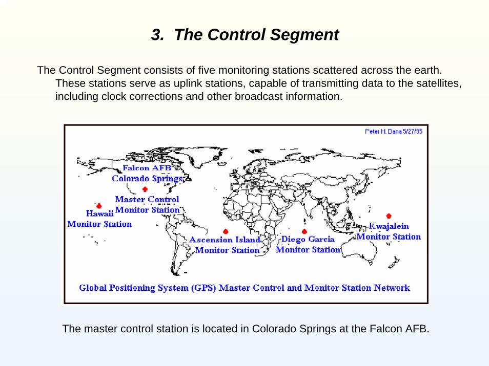
3. The Control Segment
The Control Segment consists of five monitoring stations scattered across the earth. These stations serve as uplink stations, capable of transmitting data to the satellites, including clock corrections and other broadcast information.
The master control station is located in Colorado Springs at the Falcon AFB.

How GPS Works
The GPS satellites circle the earth twice a day in a very precise orbit,approximately 12,600 miles above the Earth.

As the satellites orbit, they continuously transmit radio signals towards the earth.
These radio signals travel at the constant speed of light (186,000 miles per second).
The radio signals are generated by the satellite’s atomic clocks.

The GPS receiver receives the radio signals and uses Isaac Newton’sLaw of Motion to calculate the distance to each satellite.
Velocity x Time = Distance
Velocity = Speed of the radio frequencies (186,000 mi/sec).
Time = Difference between when the radio signals were sent by the satellites and when they were received by theGPS receiver.
Calculating the signal time difference is commonly referred to as “satellite ranging”.

GPS Difference in Time
“Satellite Ranging”

The radio frequencies that are being broadcasted by the satellites travel on a fundamental frequency of 10.23 Mhz. This frequency “carries” two timing signals called L1 and L2.
L1 is carried (broadcasted) at 1575.42 Mhz
L2 is carried (broadcasted) at 1227.60 Mhz
The L1 frequency contains two mathematical codes - the Coarse Acquisition (C/A) code and the Precision (P) code.
The L2 frequency only carries the P code. Since the P code on L2 is broadcasted on a different frequency than the P code on L1, it can be used as an independent timing source.
The L1 and L2 codes are “decoded” to help the receivers distinguish between the satellites and calculate the ranging time of the broadcasts.
Satellite Radio Frequencies

GPS Distance and Time Measurement Data
In total, there are five pieces of data that a GPS receiver can take measurements from:
1. The L1 frequency rate.
2. The information from the C/A code
on L1.
3. The information from the P code on L1.
4. The L2 frequency rate.
5. The information from the P code on L2.
The more pieces of data a GPS receiver can mathematically measure and compute, the greater the accuracy. And the more satellites a GPS receiver can “see” at any given time, the more information it can receive, process and compute…and thus the greater the precision.

Calculating a GPS PositionAs previously mentioned, the GPS receiver decodes the L1 and/or L2 timing signals from the “visible”
satellites and, having calculated their distances, uses triangulation to compute its own latitude, longitude, elevation and time.
When a user takes a GPS position, they are basically taking a “snapshot” of the GPS range and distance calculations being processed by the GPS receiver at that particular place, space and time.
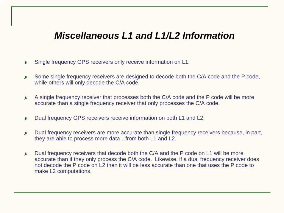
Miscellaneous L1 and L1/L2 Information
Single frequency GPS receivers only receive information on L1.
Some single frequency receivers are designed to decode both the C/A code and the P code, while others will only decode the C/A code.
A single frequency receiver that processes both the C/A code and the P code will be more accurate than a single frequency receiver that only processes the C/A code.
Dual frequency GPS receivers receive information on both L1 and L2.
Dual frequency receivers are more accurate than single frequency receivers because, in part, they are able to process more data…from both L1 and L2.
Dual frequency receivers that decode both the C/A and the P code on L1 will be more accurate than if they only process the C/A code. Likewise, if a dual frequency receiver does not decode the P code on L2 then it will be less accurate than one that uses the P code to make L2 computations.
GPS Measurement Considerations
There are several factors to consider when taking a GPS position. Some of these include:
1. Number of Visible Satellites
2. Satellite Dilution of Precision (DOP)
3. GPS Error Sources
4. GPS Limitations

1. Number of Visible Satellites
A computed GPS position can vary in accuracy depending on how many and which satellites are used for measurements.
As stated previously, the more satellites the GPS receiver can “see” the better your accuracy. That is why having 8 visible satellites will usually result in a more accurate position than only viewing 5.
Calculations are needed from at least 4 visible satellites (above a 15 degree elevation mask) for a single point, 3D measurement (latitude, longitude and height) with time.

Determining an Single Point, 3D Position
Adding another distance measurement to a second satellite narrows down the position possibility.
It starts by determining the distance between a GPS satellite and the receiver’s position.

Determining an Single Point, 3D Position, continued
Three distances = somewhere within two points
Four distances = one point

2. Satellite Dilution of Precision (DOP)
Þ The Dilution of Precision is a measure of the strength of satellite geometry and is related to the spacing and position of the satellites in the sky.
Þ Four types of DOP Dimensions:
1. HDOP – Horizontal Only 2. VDOP – Vertical Only3. PDOP – Positional in 3D 4 . GDOP – Geometric in 3D and Time
Þ The most useful DOP is the GDOP, since this a combination of allthe factors…vertical, horizontal, 3D and time.
Þ The lower the DOP value, the better the satellite geometry.

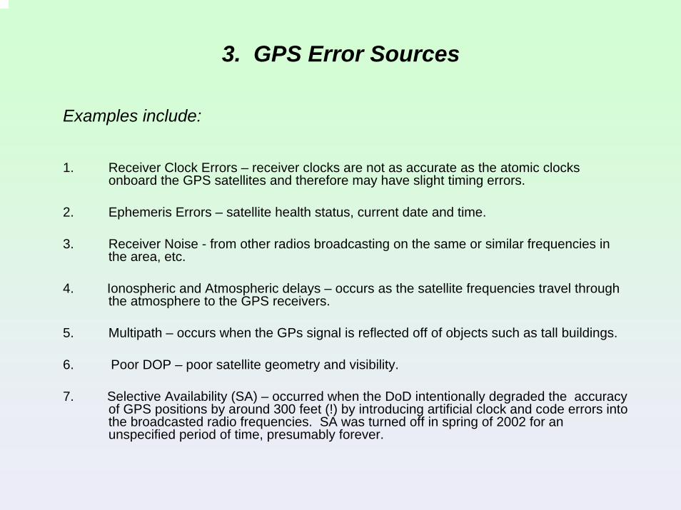
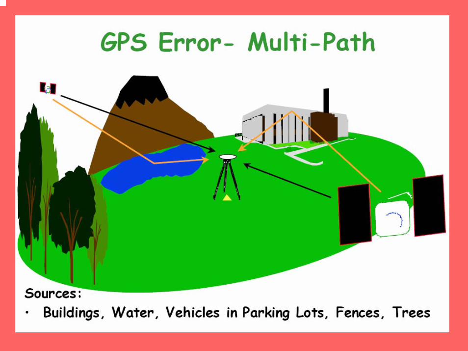
3. GPS Error Sources
Examples include:
1. Receiver Clock Errors – receiver clocks are not as accurate as the atomic clocks onboard the GPS satellites and therefore may have slight timing errors.
2. Ephemeris Errors – satellite health status, current date and time.
3. Receiver Noise - from other radios broadcasting on the same or similar frequencies in the area, etc.
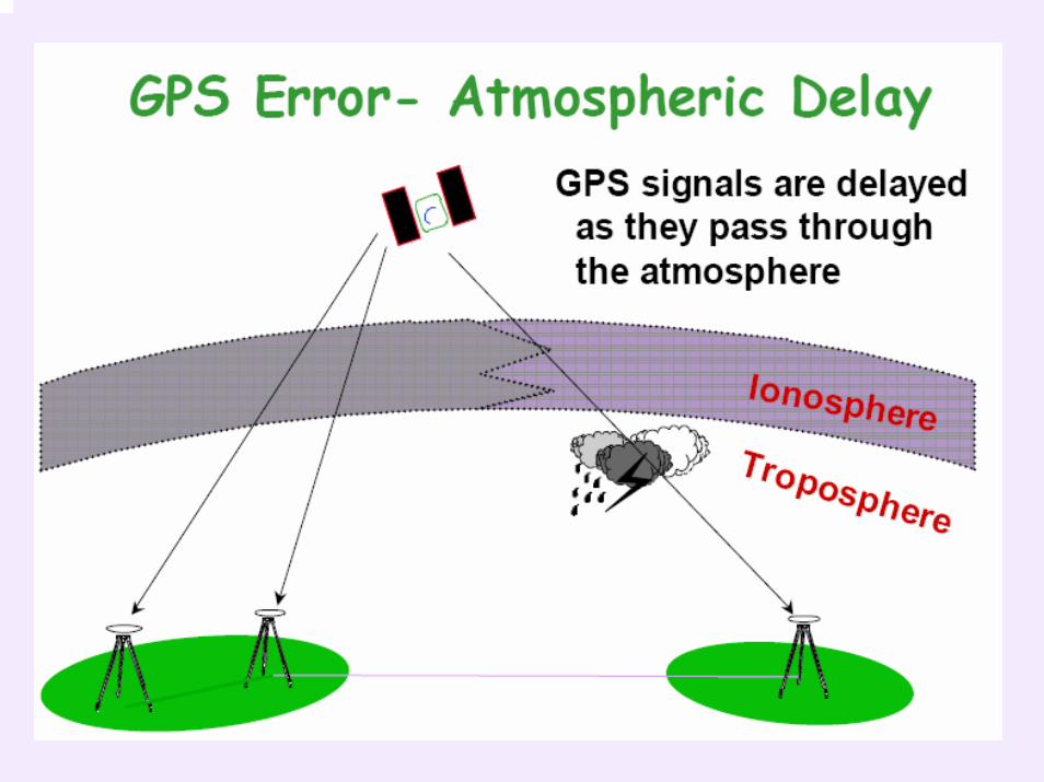
4. Ionospheric and Atmospheric delays – occurs as the satellite frequencies travel through the atmosphere to the GPS receivers.
5. Multipath – occurs when the GPs signal is reflected off of objects such as tall buildings.
6. Poor DOP – poor satellite geometry and visibility.
7. Selective Availability (SA) – occurred when the DoD intentionally degraded the accuracy of GPS positions by around 300 feet (!) by introducing artificial clock and code errors into the broadcasted radio frequencies. SA was turned off in spring of 2002 for an unspecified period of time, presumably forever.

Examples of GPS Error Sources per Satellite
Receiver clock errors can degrade accuracy up to.……~ 5 ft.
Receiver noise can degrade accuracy up to……………~ 1 ft.
Atmospheric delays can degrade accuracy up to…… ~ 18 ft.
Multipath can degrade accuracy up to………………… ~ 2 ft.
Total accuracy degradation from just the above possibleerror sources is approximately 26 feet!!
*** Many GPS error sources can be significantly reduced, if not completely eliminatedby using differential corrected GPS (DGPS), which will be explained later.

4. GPS Limitations
1) GPS requires a clear view to at least 4 satellites (5 for sub meter work).
2) Remove one or more satellites out of your triangulation equation and your results (solutions) change.
A clear view to at least 4 satellites

GPS Limitations, continued
3) GPS cannot be used indoors, around a bunch of tall buildings, or in heavily wooded areas.
Large objects can block the GPS signal.
Miscellaneous Notes
The further out the GPS satellite is, the more errors are likely to be induced in the receiver’s calculations, which degrades the accuracy. Therefore, as a general rule, a 15 degree elevation mask is set within the GPS receiver so that only the satellites located 15 degrees above the horizon are used in distance calculations.
The GPS satellites are referenced to the World Geodetic System of 1984 (WGS84) ellipsoid. Therefore, all GPS receivers collect WGS84 coordinates (latitude and longitude).
For surveying and mapping purposes, the WGS84 coordinate system must be converted (i.e. transformed) to a user-defined datum, such as the North American Datum of 1983 (NAD83).
For more information on coordinate systems, including State Plane Coordinate Systems, Projections, Ellipsoid (WGS84) vs Orthometric (ground) heights please visit:
www.colorado.edu/geography/gcraft/notes/coordsys/coordsys.html

Mission Planning
“Plan your work and work your plan!”
i Mission planning software helps determine when to go out in the field by providing daily times for “seeing” the greatest number of satellites via satellite almanacs and therefore maximize efficiency .
i Mission planning software shows you when you have the best DOP values with the greatest number of visible satellites and therefore compute a higher accuracy position.
i Mission planning also helps ensure the safety and security of personnel by being aware of hazardous weather, satellite obstacles and etc.

Example of Satellite Almanac Information
Each satellite transmits almanac data showing orbital information for every satellite in the system.

Methods of GPS Data Acquisition
1. Static
2. Rapid-Static
3. Real-Time Kinematic (RTK)

1. Static – used to establish long base lines and forsetting control.
@ Requires that the GPS receivers sit on a point for a long period of time collecting data from the satellites before moving to the next point.
@ Generally used to obtain high accuracy positions.
@ Collected data is later post-processed at the office using specialized processing software that computes and compares the GPS position(s).
@ Accuracies can be achieved as high as 0.0066 ft horizontally, depending how long you occupy each point and how many satellites are visible with good satellite geometry.
2. Rapid Static – for establishing shorter lines and boundaries.
K Similar to Static GPS but the receivers do not sit on a point as long beforemoving to the next one and thus does not collect as much information forpost-processing.
K Rapid-Static is less accurate than static GPS.
K Can achieve accuracies as high as 0.0164 ft horizontally.

3. Real-Time Kinematic (RTK) - allows you to view your datain the field as you collect.
d Allows you to take positions very quickly by occupying the point for only a minute or less, even down to a just a couple of seconds in a good GPSenvironment. ***
d Accuracies range from 0.0328 ft to 0.0656 ft. horizontally.
d RTK GPS is less accurate than static and rapid-static GPS but is a lot fasterand allows you to view your results while you are collecting it, rather than havingto wait until you are back in the office to post-process.
(*** An open area with a high number of visible satellites and good geometry.)

GPS Accuracy Classifications
1. Autonomous Navigation1. Autonomous Navigation(15 to 100 ft horizontally)(15 to 100 ft horizontally)
2. Differentially Corrected (DGPS)2. Differentially Corrected (DGPS)(1 to 15 ft horizontally)(1 to 15 ft horizontally)
3. Differential Phase Position3. Differential Phase Position(less than 1 foot horizontally)(less than 1 foot horizontally)
(As a general rule, vertical accuracies are usually 2 – 3 times lower than the horizontal accuracy.)

1. Autonomous Navigation
(Single Frequency)
B The GPS receiver uses only the information that is being broadcasted by the satellites to compute a position.
B Autonomous GPS results in an approximate “uncorrected” position.
B Position accuracy ranges from ~ 15 to 100 ft.
B Generally uses a single stand-alone “hand-held” receiver.
B Used mainly by hikers, boaters, and the military.
B Costs range from about $100.00 to $500.00 per unit.

2. Differently Corrected GPS (DGPS)(Single Frequency)
DGPS requires that your GPS unit receives “corrected” positional information that is broadcasted from another stationary receiver and/or geostationary satellite (i.e. a known point), in addition to the information already being received from the NAVSTAR satellites.
Known Point
Corrected Signal
GPS Receiver
Since this secondary stationary receiver/satellite “knows” where it is, it can compute the errors in its position and apply them to any number of roving receivers in the same general area.

DGPS in Action

DGPS, Continued
. Accuracies range from 1.0 to 15 ft, depending on the number of channels, tracking capabilities, size of the system’s internal data processor to process the satellite and correctional information, etc.
. Used mainly for GIS data acquisition, inshore marine navigation, precision farming, and etc.
. Costs range from about $500.00 to around $12,000.00 for complete packages (including software).
. As mentioned earlier, many of the errors affecting GPS measurements can be completely eliminated or at least significantly reduced using DGPS techniques.

DGPS Correction Options
Several options are available for obtaining differential GPS corrections:
1. Use another GPS receiver as a stationary base that is mounted on a known point, yet can be moved to other known points as needed.
2. Use a CORS site (Continuously Operating Reference Station) which is a permanently mounted GPS receiver/transmitter.
3. U.S. Coast Guard Beacon Ground Network – a network of land-based correctional broadcast towers, usually near major navigable bodies of water. Sends out a single frequency signal only.
* Advantage: Free of Charge
* Disadvantage: Requires a beacon receiver and antenna;coverage is limited to within ~60 miles ofthe beacon station.

DGPS Correction Options, continued
4. Use other satellite systems (in addition to NAVSTAR) to receive position corrections.
Examples include:
a. WAAS – (Wide Area Augmentation System) – established by the Federal AviationAdministration (FAA) and is free of charge. Although not officially complete, many GPSmanufacturers are incorporating WAAS capabilities into newer, lower-cost receivers and iscurrently available for civilian use within the United States.
WAAS is made up of two geostationary satellites that broadcast corrected GPS data and 25 ground monitoring stations that are positioned across the United States to monitor thesatellite data and upload corrections to the satellites.
A good WAAS information website: www.garmin.com/aboutGPS/waas
b. RACAL Land-Star - commercially owned geostationary satellite system with ground monitoringstations; available in over 40 countries; requires an approximate $800/year subscription and a proprietary Racal receiver and GPS antenna.
Racal information website: www.navtechgps.com/supply/racal
c. Omni-Star – essentially the same as the Land-Star but just a different manufacturer.

Examples of GPS Base Stations for DGPS Corrections
U.S. Coast Guard lighthouse with beacon antenna.
CORS permanently mounted GPS base receiver.
GPS base receiver mounted on a known position, but capable of moving from point to point as needed.

3. Differential Phase Position GPS(Dual Frequency)
! Requires the use of at least two dual-frequency L1/L2 receivers…a base and a rover.
! The stationary base is mounted on a known point and sends corrections to the rover via radios, cell phones, internet, etc.
! The dual-frequency base not only sends corrections based on the calculations from the L1 and L2 frequencies, but is usually a lot closer than a beacon station and/or a geostationary satellite.
! Same basic techniques as DGPS methods, except in the way satellite ranges are calculated due to the L1 and L2 dual-frequency channels.
! Accuracies range from 0.0066 ft (static measurements) to less than 1 ft (real-time).
! Used mainly for surveying, machine control and etc.
! Costs range from $20,000 to around $50,000 with software and training.
GPS Base
GPS Rover

Purchasing Considerations
Accuracy
Applications
Battery Life
Communication Options for DGPS
Compatibility with Office Software
Coordinate Systems
Data Input/Output Formats
Ease of Use
Error Reduction Capabilities
Flexibility and Expandability
L1 and L2 Channels and Codes Used in Computations
Output to Other Devices
Post-processing and/or Real-Time Capabilities
Price
Ruggedness
Size and Weight
Satellite Tracking Capabilities
Technical Support
Training
DO YOUR HOMEWORK…RESEARCH YOUR OPTIONS BEFORE BUYING!!

Conclusion
In conclusion, GPS receivers vary greatly in accuracy, data processing capabilities, communication and interfacing options, software….and price.
Think of a GPS receiver (either single or dual-frequency) as a computer with an antenna. The more powerful and efficient the receiver processor and the better the tracking and filtering capabilities of the antenna, the faster and more precise the GPS system.