Embed Size (px)
Citation preview

18
Principal Screws and Full-Scale Feasible Instantaneous Motions of Some
3-DOF Parallel Manipulators Z. Huang, J. Wang and S. H. Li
Robotics Research Center, Yanshan University P. R. China
1. Introduction With the development of parallel robot, various lower-mobility parallel mechanisms are proposed, especially, the 3-DOF parallel mechanisms have interested many researchers. Hunt (1983) proposed the first 3-DOF 3-RPS parallel mechanism. Lee and Shah (1988) addressed various possible applications of the mechanism. Waldron et al. (1989) studied an ARTISAN manipulator. Clavel (1988) proposed the DELTA. Gosselin and Angeles (1988, 1989) proposed an optimum kinematic design for planar and spherical 3-DOF parallel manipulators. Song (1995) studied a force-compensating device based on 3-RPS mechanism. Huang and Fang (1996) proposed some novel 3-DOF parallel mechanisms. Di Gregorio (1999) discussed the influence of flexibility of a 3-DOF parallel mechanism on the platform motion. We know that a primary and basic step towards understanding a mechanism is to find all the feasible instantaneous motions or twists it can produce. In other words, it needs to determine both the range of the twist pitches and the distribution of the twist axes. It is important to correctly use a robot manipulator and plan its trajectory. In robotics practice, for a six-DOF manipulator its end-effector has infinite moving possibility and can undergo any given twist in 3D space. For a lower-mobility manipulator it also has infinite moving possibility, however, it is clear that there are many motions impossible to realize. To find all the feasible instantaneous motions of a lower-mobility serial robot is easier than that of the 6-DOF one. The possible twists of a lower-mobility serial robot are obtained only by the linear combination of its joint screws. Nevertheless, for lower-mobility parallel mechanism, it is extraordinary difficult. To solve the problem we use the screw theory. One hundred years ago Ball (1900) published his classical work on screw theory. Hunt (1978) further developed screw theory. He discussed all the screw systems. The screw systems were distinguished as general and special cases basically according to the pitches of principal screws. Gibson & Hunt (1990 a & b) classified first-order, second-order and third-order screw system further by means of projective geometry and gave the planar representation of the general three-system. Any screw motion of a 3-DOF rigid body can be expressed by a linear combination of its three principal screws in the three-system. The spatial distribution of axes of all the screws of the screw system in three-dimension space is

Parallel Manipulators, New Developments
350
regular. For example, all the screws of the second-order screw system lie on a cylindroid. For a third-order screw system or three-system, all the screws with the same pitch may lie on a hyperboloid of one sheet. The cylindroid or hyperboloid depicts the distributions of the positions and orientations of all screw axes of that screw system. The key to determine both the range of the twist pitches and the distribution of the twist axes in three-dimension space is to get principal screws of the screw system. The principal screw is a very important concept in screw theory. After the principal screws are obtained, it is easy to know all possible motions of the mechanisms at a the given instant. In a second-order screw system there are two principal screws. For a third-order screw system, there exist three principal screws. The third-order screw system is the most important and complicated one. The twist screw system of a 3-DOF parallel mechanism is a third-order screw system. To study the mechanism, we need to determine its three principal screws. Parkin (1990) specified the principal screws of the three-system from three given screws by adopting the mutual moment operation. Tsai & Lee (1993) studied the principal screws from three known screws by means of eigenvector. Zhang & Xu (1998) constructed the principal screws from three known screws by using algebraic method. From another point of view, we put forward a directly and simply analytical method for identifying the principal screws for a 3-DOF parallel mechanism and obtained a full-scale feasible instantaneous motion of that mechanism. Fang & Huang (1998) firstly established the important relationship between the principal screws and Jacobian matrix of the 3-DOF mechanism, and identified the principal screws of the third-order screw system using the quadratic equation degenerating theory. After that, based on the relationship between the pitch/axis and the Jacobian matrix of the mechanism two equations are obtained. Then, another simpler and more effective principle (Huang & Wang 2001), the quadric degenerating theory, was further proposed for identifying the principal screws. For applying the principle to lower-mobility parallel mechanisms, corresponding two 33× Jacobian matrices are needed to establish firstly. This can be realized by using the imaginary-mechanism method proposed by Yan & Huang (1985) and developed by Huang & Wang (1992). In this Chapter two typical examples are also discussed. One is a 3-DOF 3-RPS parallel manipulator (Huang & Wang, 2002). Another example is a special 3-UPU parallel mechanism (Huang, Li & Zuo, 2004). The analysis discovers this mechanism has some interesting and exceptional characteristics. All above analysis are important for enriching the mechanism theory and beneficial the mechanical design of the similar mechanical system.
2. Principal screws The principal screw principle may be used to study the feasible instant motion. Its important merit is that it can illustrate a full-scale feasible instantaneous motion of a mechanism at any given configuration.
2.1 The screw representation In screw theory (Ball, 1900; Hunt, 1978 & Huang, et al, 2006), a straight line in 3D space can be expressed by two vectors, S and S0. Their dual combination is called a line vector, (S, S0). The line vector can be expressed as

Principal Screws and Full-Scale Feasible Instantaneous Motions of Some 3-DOF Parallel Manipulators
351
( ) ( ) ( )= = × =0; ;l m n p q r$ S S S; r S
where S is a unit vector along the straight line; l, m, and n are three direction cosines of S; p, q, and r are the three elements of the cross product of r and S; r is a position vector of any point on the line or the line vector. (S; S0) is also called Plücker coordinates of the line vector and it consists of six components in total. For a line vector we have ⋅ =0 0S S . When S· S= 1,
it is a unit line vector. When =0S 0 , the line vector, ( );S 0 , passes through the origin point. When ⋅ ≠0 0S S , it is defined as a screw
( ) ( )= = × +0; ; h$ S S S r S S (1)
When ⋅ = 1S S , it is a unit screw. The pitch of the screw is
= ⋅ ⋅0h S S S S
If the pitch of a screw is equal to zero, the screw degenerates into a line vector. In other words, a unit screw with zero-pitch (h = 0) is a line vector. The line vector can be used to express a revolute motion or a revolute pair in kinematics, or a unit force along the line in statics. If the pitch of a screw goes to infinity, = ∞h , the screw is expressed as
( ) ( )= =0 ; 0 0 0; l m n$ S
and called a couple in screw theory. That means a unit screw with infinity-pitch, = ∞h , is a couple. The couple can be used to express a translation motion or a prismatic pair in kinematics, or a couple in statics. S is its direction cosine. Both the revolute pair and prismatic pair are the single-DOF kinematic pair. The multi-DOF kinematic pair, such as cylindrical pair, universal joint or spherical pair, can be considered as the combination of some single-DOF kinematic pairs, and represented by a group of screws. The twist motion of a robot end-effector can be described by a screw. The linear velocity
Pv of a selected reference point P on the end-effector and the angular velocity ω of the end-effector are given according to the task requirements. Therefore, the screw of the end-effector can be expressed by the given kinematic parameters Pv and ω
( )= +∈ = +∈ + ×oi P P$ ω v ω v r ω
where ∈ is a dual sign; ov is the velocity of the point coincident with the original point in the body; rP is a positional vector indicating the reference point on the end-effector of the manipulator. When the original point of the coordinate system is coincident with point P, the pitch and axis can be determined by the following two equations
⋅
=⋅
Ph ω vω ω
(2)

Parallel Manipulators, New Developments
352
× = −P hr ω v ω (3)
If a mechanism has three DOF, the order of the screw system is three. The motion of the three-order mechanism can be determined by three independent generalized coordinates. These independent generalized coordinates are often selected as three input-pair rates. The
Pv and ω of a robot can then be determined by these three input joint rates
[ ][ ]==
P GG'
v qω q
{ }= 1 2 3Tq q qq (4)
where [G] and [G’] are 3×3 first-order influence coefficient matrices (Thomas & Tesar, 1983). Substituting Eq. (4) into Eqs. (2, 3), the screw can also be described as the function of the joint rates
[ ] [ ][ ] [ ]
='
' '
TT
TT
G Gh
G G
q q
q q (5)
[ ][ ] [ ] [ ]( )= −' 'G G h Gr q q (6)
where [r] is a skew-symmetrical matrix of vector ( )=Tx y zr . Suppose we give the
following expressions
= =1 3 2 3/ ; /q q q qu w (7)
and then
( )= 31u w qq
In this case, the pitch and the axis equations are given by
{ }[ ] [ ]{ }{ }[ ] [ ]{ }
′=
′ ′
1 1
1 1
TT
TT
u w G G u wh
u w G G u w (8)
[ ][ ] { } [ ] [ ] [ ]( ){ }⎡ ⎤′ ′ ′= + −⎣ ⎦1 1T TTpG u w G G h G u wr r (9)
where [rP] is a skew-symmetrical matrix of coordinate of the point P.
2.2 Principal screws of three-order screw system A third-order screw system has three principal screws. The three principal screws are mutually perpendicular and intersecting at a common point generally. Any screw in the screw system is the linear combination of the three principal screws. In the third-order screw system, two pitches of three principal screws are extremum, and the pitches of all other screws lie between the maximum pitch and the minimum pitch. Therefore to get the

Principal Screws and Full-Scale Feasible Instantaneous Motions of Some 3-DOF Parallel Manipulators
353
three principal screws is the key step to analyze the full-scale instantaneous motion of any 3-DOF mechanism. For obtaining the three principal screws there are two useful principles, the quadratic curve degenerating theory and quadric degenerating theory.
2.2.1 Quadratic curve degenerating theory Let α β,h h and γh be pitches of the three principal screws and suppose γ α< <h h h . Ball (1900) gave a graph illustrating the full-scale plane representation of a third-order system with quadratic curves, and each quadratic curve has identical pitch. If the pitch of any screw in the system is equal to αh , βh or γh , the quadratic equation will degenerate. When
α=h h or γ=h h , the quadratic equation collapses into two virtual straight lines
intersecting at a real point; when β=h h , the quadratic equation collapses into two real straight lines (Hunt 1978). Expanding Eq. (8), we have
+ + + + + =2 211 12 22 13 23 332 2 2 0a u a uw a w a u a w a (10)
where the coefficient ( )=, , 1 ~ 3ija i j , is a function of pitch h and the elements of the
matrices [ ]G and [ ]′G . From the quadratic equation degenerating principle, the determinant of the coefficient matrix should be zero, that is
= =11 12 13
21 22 23
31 32 33
0a a aa a aa a a
D , ( )=ij jia a (11)
Expanding the Eq. (11) we have
+ + + =3 21 2 3 4 0c h c h c h c (12)
where ( )=, 1 ~ 4ic i , is a function of the elements of [ ]G and [ ]′G . Three roots of the Eq.
(12) are pitches, α β,h h and γh , of the three principal screws. Substituting the pitch of principal screw into Eq. (10), the above quadratic equation degenerates into two straight lines, the root, ( )i iu w , of the two equations is
−=
− == − −
22 13 12 232
12 11 22
23 12
22 22
1 , 2 , 3i
i i
a a a aua a a ia aw ua a
(13)
Each set of ( )ii wu corresponds three inputs ( )1ii wu . Three sets of ( )ii wu ,
α β γ= , ,i , correspond three output twists, i.e., three principal screws. When the pitches of three principal screws are obtained, substituting the three values into Eq. (9), the axis equations of three principal screws can also be obtained.
Parallel Manipulators, New Developments
354
2.2.2 Quadric degenerating theory The quadric degenerating theory is an easier method for calculating the principal screws. Eq. (6) can be further simplified as
[ ] = 0A q (14)
where
[ ] [ ][ ] [ ] [ ]′ ′= − +A G G h Gr
is a ×3 3 matrix. [ ]G and [ ]'G are also 3×3 first-order kinematic influence coefficient matrices, which are functions of the structure parameters of the mechanism. Since not all the components of vector q are zeros in general, the necessary and sufficient condition that ensures the solutions of Eq. (14) being non-zero is that the determinant of the matrix [ ]A is equal to zero. Namely (Huang & Wang 2001)
[ ] = 0Det A (15)
Expanding Eq. (15), we obtain the position equation describing all the screw axes
+ + + + + + + + + =2 2 211 22 33 12 23 13 14 24 34 442 2 2 2 2 2 0c x c y c z c xy c yz c xz c x c y c z c (16)
where the coefficients, ijc (i=1, 2, 3, 4, j=1, 2, 3, 4), are the function of pitch h as well as
coefficients ijij b,g , the latter are relative with the elements of matrices [G] and [G’] in
Appendix (Huang & Wang 2001). The Eq. (16) is a quadratic equation with three elements, x, y and z. It expresses a quadratic surface in space. The spatial distribution of all the screw axes in 3D is quite complex. Generally, all the screw axes lie on a hyperboloid of one sheet if every coefficient in Eq. (16) contains the same pitch h.
2.2.2.1 Pitches of three principal screws For a third-order screw system there exist three principal screws α , β and γ . Let αh , βh
and γh be the pitches of the three principal screws, and also suppose αh > βh > γh .
We know that the quadric surface, Eq. (16), collapses into a straight line where the principal screws α or γ lies, when αhh = or γhh = . The quadric surface degenerates into two
intersecting planes, when βhh = , and the intersecting line is just the axis of principal
screw β (Hunt 1978). According to this nature, we can identify the three principal screws of the three-system. The quadric has four invariants, D,J,I andΔ , and they are
= + +11 22 33I c c c

Principal Screws and Full-Scale Feasible Instantaneous Motions of Some 3-DOF Parallel Manipulators
355
( )
Δ = =
= + + − − − =
11 12 13 1 41 1 1 2 13
2 1 2 2 2 3 2 421 2 2 2 3
3 1 3 2 3 3 3 431 3 2 3 3
4 1 4 2 4 3 4 4
2 2 211 2 2 2 2 3 3 1 1 3 3 1 2 23 1 3
;
ij ji
c c c c c c cc c c c D c c cc c c c c c cc c c c
J c c c c c c c c c c c
(17)
Expanding D, and let it equal to zero, D = 0,we have the expression
+ + + =3 21 2 3 4 0a h a h a h a (18)
where the coefficients ai (i=1, …, 4) are also the function of ijij b,g and h. Three possible
roots can be obtained by solving Eq. (18), and these three roots correspond to pitches of the three principal screws. When the pitch in the system is equal to one of the three principal screw pitches, the invariant Δ is zero as well. It satisfies the condition that the quadric degenerates into a line or two intersecting planes. Therefore, the key to identify the principal screws in the third-order system is that the quadric, Eq. (16), degenerates into a line or a pair of intersecting planes.
2.2.2.2 The axes of principal screws and principal coordinate system The coordinate system that consists of three principal screws is named the principal coordinate system. We know that the most concise equation of a hyperboloid is under its principal coordinate system. Now, we look for the principal coordinate system of the hyperboloid. Equation (16) represented in the base coordinate system can be transformed into the normal form of the hyperboloid of one sheet in the principal coordinate system. After the pitches of the three principal screws are obtained, the pitch of any screw in the system is certainly within the range of αγ hhh << . The general three-system (Hunt 1978) appears only when
three pitches of the three principal screws all are finite and also satisfy αβγ hhh ≠≠ . The
axes of all the screws with the same pitch in the range from γh to βh or from βh to αh
form a hyperboloid of one sheet. In this case the invariant D is not equal to zero, and the quadrics are the concentric hyperboloids. By solving Eq. (19)
+ + + =⎧⎪ + + + =⎨⎪ + + + =⎩
11 12 13 14
21 22 23 24
31 32 33 34
000
c x c y c z cc x c y c z cc x c y c z c
(19)
the root of Eq. (19) is just the center point o’ ( )0 0 0x y z of the hyperboloid. It is clear that
the point o' is also the origin of the principal coordinate system. The coordinate translation is

Parallel Manipulators, New Developments
356
= +⎧
⎪ = +⎨⎪ = +⎩
0
0
0
'''
x x xy y yz z z
(20)
The eigenequation of the quadric is
− + − =3 2k Ik Jk D 0 (21)
Its three real roots k1, k2, k3 are the three eigenvalues, and not all the roots are zeros. In general, ≠ ≠1 2 3k k k . The corresponding three unit eigenvectors
( )λ μ ν1 1 1 , ( )λ μ ν2 2 2 and ( )λ μ ν3 3 3 are perpendicular each other, and
corresponding three principal screws, α β γ, and , form the coordinate system (o'-x'y'z'). The principal coordinate system (o'-αβλ ) can then be constructed by a following coordinate rotation
λ λ λμ μ μν ν ν
= + +⎧⎪ = + +⎨⎪ = + +⎩
1 2 3
1 2 3
1 2 3
' ' '' ' '' ' '
x x y zy x y zz x y z
(22)
After the coordinate transformation, the normal form of the hyperboloid is
Δ
+ + + =2 2 21 2 3 0k x k y k z
D (23)
Fig.1. Hyperboloid of one sheet

Principal Screws and Full-Scale Feasible Instantaneous Motions of Some 3-DOF Parallel Manipulators
357
Hunt (1978) gave that when h lies within the range β α< <h h h , the central symmetrical axis
of the hyperboloid is α ,and the semi-major axis of its central elliptical section in the βγ -
plane always lies along β . For γ β< <h h h ,the central symmetrical axis of the hyperboloid
is γ ,and the semi-major axis of its central elliptical section in the βγ -plane is also along β , Fig.1. Therefore, we may easily determine the three axes of the principal coordinate system.
3. Imaginary mechanism and Jacobian matrix In order to determine the pitches and axes using Eqs. (4-9), the key step is to determine ×3 3 Jacobian matrices [G] and [G’]. For a 3-DOF parallel mechanism to determine the [G]
and [G’] is difficult. Here the imaginary-mechanism principle (Yan & Huang, 1985; Huang & Wang, 1992) can solve the issue easily. Note that, the imaginary-mechanism principle with unified formulas is a general method, and can be applied for kinematic analysis of any lower-mobility mechanism. An example is taken to introduce how to set the matrices [G] and [G’]. Fig. 2(a) shows a 3-DOF 3-RPS mechanism consisting of an upper platform, a base platform, and three kinematic branches. Each of its three branches is comprise of a revolute joint R, a prismatic pair P and a spherical pair S, which is a RPS serial chain. The axes of three revolute joints are tangential to the circumcircle of the lower triangle. The mechanism has three linear inputs, 1 2 3, ,L L L .
a) Mechanism sketch b) Imaginary branch
Fig.2. 3-DOF 3-RPS parallel mechanism

Parallel Manipulators, New Developments
358
3.1 Imaginary twist screws of branches Each kinematic branch of the 3-RPS mechanism may be represented by five single-DOF kinematic pairs as RPRRR. In order to get the Jacobian matrix by means of the method of kinematic influence coefficient of a 6-DOF parallel mechanism (Huang 1985), we may transform this 3-DOF mechanism into an imaginary 6-DOF one in terms of the kinematic equivalent principle. An imaginary link and an imaginary revolute pair, $0, with single-DOF, are added to each branch of the mechanism. Then each branch becomes an imaginary 6-DOF serial chain. In order to keep a kinematic equivalent effect, let the amplitude ω0 of the imaginary screw $0 of each branch always be zero; and let each screw system formed by imaginary $0 and the other five screws of the primary branch RPRRR be linearly independent. Considering the imaginary pair $0, the Plücker coordinates of all six screws shown in Fig. 3b with respect to local o-X1Y1Z1 coordinate system are
{ }{ }{ }
ζ===
1
2
3
1 0 0 ; 0 0 00 0 0 ; 0 ψ0 ψ ζ ; 0 0 0
$$$
{ }{ }{ }
ζ= −= − −=
4 0 0
5 0
0
1 0 0 ; 0 ζ ψ0 ψ ; 0 00 0 1 ; ' 0 0
L LL
L
$$$
(24)
where ψ and ζ are directional cosines of the screw axes 2$ and 3$ . The screw matrix of each branch with respect to the local coordinate system is
{ }=⎡ ⎤⎣ ⎦ 0 1 2 3 4 5, , , , ,Gg $ $ $ $ $ $ , and we have ⎡ ⎤ ⎡ ⎤= ⎡ ⎤⎣ ⎦⎣ ⎦ ⎣ ⎦0 0i iG A Gg .
3.2 Imaginary Jacobian matrix For each serial branch, the motion of the end-effector of the 3-RPS mechanism can be represented by the following expression
( )⎡ ⎤= =⎣ ⎦0 1 ,2 , 3i
H iG iV φ (25)
where { }=T
H PV ω v is a six dimension vector; ω is the angular velocity of the moving
platform; vP is the linear velocity of the reference point P in the moving platform; and ( ) ( ) ( ) ( ) ( ) ( ) ( )( )= φ φ φ φ φ φi i i i i i i
0 1 2 3 4 5φ is a vector of joint rates. If ⎡ ⎤⎣ ⎦0iG is non-
singular
( ) ⎡ ⎤= =⎣ ⎦0 1 , 2 , 3i iHG iφ V (26)
where −
⎡ ⎤ ⎡ ⎤=⎣ ⎦ ⎣ ⎦1i 0
0G iG
The input rates 1 2 3L ,L , L of the mechanism are known and the rate of each imaginary link is zero, which is equal to known. Then for each branch we have
( ) ( )( ) ( )( )φ φ φ φ φ φ 0 φ φ φ φ= = =1L 1,2,3iii
0 1 2 3 4 5 1 3 4 5 iφ (27)

Principal Screws and Full-Scale Feasible Instantaneous Motions of Some 3-DOF Parallel Manipulators
359
Taking the first row and third row from the matrix ⎡ ⎤⎣ ⎦0iG in Eq. (26) of each branch, there are
six linear equations. A new matrix equation can be established
⎡ ⎤= ⎣ ⎦qH HGq V { }= 1 2 3 0 0 0L L Lq (28)
where
×⎡ ⎤⎡ ⎤ ⎡ ⎤ ⎡ ⎤ ⎡ ⎤ ⎡ ⎤ ⎡ ⎤ ⎡ ⎤= ∈⎣ ⎦ ⎣ ⎦ ⎣ ⎦ ⎣ ⎦ ⎣ ⎦ ⎣ ⎦⎣ ⎦ ⎣ ⎦1 2 3 1 2 3 6 60 0 0 0 1: 0 03: 3: 3: 1: 1:
TqHG G G G G G G R
where ⎡ ⎤⎣ ⎦0 :i
iG represents the ith row of matrix ⎡ ⎤⎣ ⎦0iG . If the matrix ⎡ ⎤⎣ ⎦
qHG is non-singular,
from Eq. (28)
⎡ ⎤= ⎣ ⎦H
H qGV q (29)
where
−
⎡ ⎤⎡ ⎤ =⎣ ⎦ ⎣ ⎦1qH
q HG G (30)
Since the 3-RPS mechanism has three freedoms, it needs three inputs. The matrix ⎡ ⎤⎣ ⎦HLG
formed by taking the first three columns of the matrix ⎡ ⎤⎣ ⎦HqG is a 6× 3 Jacobian matrix.
Therefore
⎡ ⎤= ⎣ ⎦H
H LGV L (31)
As { }=T
H PV ω v , Eq. (31) can be separated into two equations
[ ]= Gpv L; [ ]′= Gω L (32)
where [ ]′G is the first three rows of ⎡ ⎤⎣ ⎦HLG ; [ ]G is the last three rows of ⎡ ⎤⎣ ⎦
HLG . Then we
obtain the 3× 3 matrices [G] and [G’]. From the analysis process we know that the matrices
[ ]G and [ ]G′ are independent of the chosen of these imaginary pairs.
4. Full-scale feasible instantaneous screws of 3-RPS mechanism Now, we continue to study the 3-RPS mechanism, Fig. 2, to get the full-scale feasible instantaneous motion. The parameters of the mechanism are:R=0.05 m; r=0.05 m; L0=0.2 m; L’=0.04 m. Three configurations will be discussed.
4.1 Upper platform is parallel to the base Substituting given geometrical parameters and expanding Eq. (8), we have Eq. (10)

Parallel Manipulators, New Developments
360
+ + + + + =2 211 12 22 13 23 332 2 2 0a u a uw a w a u a w a (33)
Eq. (33) is a quadratic equation with two variables, u and w. It will degenerate, if Equation (11) is satisfied. Expanding Eq. (11) we have the Eq. (12)
+ + + =3 2 0ah bh ch d (34)
The three roots of Eq. (34) are just three pitches of the three principal screws. Substituting each root h into Eq. (33) the quadratic equation degenerates into two linear equations expressing two straight lines. The intersecting point (u, w) of the two lines can be obtained. Then, the axis of the principal screw can also be obtained by using Eq. (9). When the moving platform is parallel to the fixed one, it follows that: = = = = 0a b c d ; i.e., all the coefficients of Eq. (34) are zeroes. From algebra, the three roots, h, can be any constant. For some reasons, which we will present below, however, the three roots of Eq. (34) should be ( )∞ 0 0 . When →∞h ,we have = 1u , = 1w , then the inputs are
{ } { }= =1 1 1 1u wL . The output motion is a pure translation, namely
{ }=1 0 0 0 ; 0 0 1Z$ . When the pitch of the principal screw is zero,
= 0h , = 0 /0u ; 00 /w = . Mathematically, u and w both can be any value except one. All other roots of Eq. (34) will not be considered, as they are algebraically redundant. Then, the corresponding three principal screws can be written as
{ }{ }{ }
== −=
1
2
3
0 0 0 ; 0 0 10 1 0 ; 0 01 0 0 ; 0 0
z
z x
z z
PP
$$$
(35)
Fig. 3. The spatial distribution of the screws when the upper parallel to the base
Any output motion may be considered as a linear combination of the three principal screws. The full-scale distribution result, Fig.3, of all screws obtained by linear combinations of three principal screws can also be verified by using another method presented in Huang et al.,

Principal Screws and Full-Scale Feasible Instantaneous Motions of Some 3-DOF Parallel Manipulators
361
(1996), and is identical with the actual mechanism model in our laboratory. The three principal screws belong to the fourth special three-system presented by Hunt (1978). When the upper platform is parallel to the fixed platform, all possible output twists of the upper platform except the translation along the Z direction are rotations corresponding screws with zero pitch. Their axes all lie in the moving platform and in all the directions. Fig. 3 shows the full-scale possible twist screws with zero-pitch. Therefore from this figure you don’t attempt to make the moving platform rotate round any axis not on the plane shown in Fig. 3. That is impossible.
4.2 The upper platform rotates by an angle α about line a2a3 When the upper platform continually rotates by an angle α about line a2a3,namely the mechanism is in the configuration that the lengths of the two input links are the same. Note that, for this kind of mechanisms the platform cannot continually rotate about axes lying in the plane shown in Fig.3 except some three axes including a2a3. In other words, it is very often impossible that the platform can continually rotated about an axis lying in the plane, as shown in Fig.3, (Zhao et al, 1999). The coordinates of point a1 on the upper platform and point A1 on the base have the following values
( ){ }α α= − +1 03cos 1 /2 0 3 sin /2a r L r { }=1 0 0RA (36)
In this configuration, the screw system including the imaginary pair of the first chain
corresponding to [ ]01G with respect to the fixed coordinate system is
{ } { }{ } { }{ } { }{ } { }{ } { }{ }
= = ×= == = ×= = ×= = × × × ×
′= −
1 1
1
4 4 4 1
5 5 5 4 1 4 4
0 0 0 1 ; 0 0
1 01 1 1
2 2 02 1 1
3 3 03 1 1 1
0 1 1
0 1 1 1
; ;; ; /; ; /; ;; ; /
L
$ S S S A S$ S S 0 L L$ S S L a L L$ S S S a S$ S S L S a L S L S$
(37)
where { }= = −1 4 0 1 0S S , = −1 11L a A .
The twist screw systems of the other two chains corresponding ⎡ ⎤⎣ ⎦02G and ⎡ ⎤⎣ ⎦
03G are the
same as the case that the upper platform is parallel to the base. Establishing matrices [ ]G
and [ ]′G , we can solve principal screws by using the previous method.
Suppose α °= 30 ,the pitches of three principal screws can be obtained by solving Eq. (34).
They are α β γ= × = = − ×5 55.13 10 ; 0 ; 5.13 10h h h . When =2 0I , where 2I is the two-order
determinant of coefficients of the quadratic equation,its two roots are
= −1 0.0057h , =2 0.0165h . There are six types of the quadratic curve for the same configuration of the mechanism, as shown in Table 1. The pitch h varies between hα and hγ.

Parallel Manipulators, New Developments
362
Each point in Fig. 4 denotes a pitch h of a twist screw of the moving platform relative the three inputs (u, w, 1). You can get the output pitch of the instantaneous twist when three inputs are given. Fig.4 also shows the relation between inputs and the six types of quadratic curves with different pitches in this configuration of the mechanism.
Fig. 4. When the upper platform rotates °30 about a2a3
The range of the value of h In 30° configuration In general configuration
Type of conics
< < × 50.0165256 5.13 10h or − × < < −55.13 10 0.0057003h
< < × 50.0131215 4.28 10h or − × < < −54.28 10 0.0160208h
Real ellipse
> × 55.13 10h or < − × 55.13 10h 510284 ×> .h or 510284 ×−< .h Imaginary
ellipse
α = × 55.13 10h or γ = − × 55.13 10h α = × 54.28 10h or γ = − × 54.28 10h Dot ellipse
0165256000570030 .h. <<− 0131215001602080 .h. <<− Hyperbola
0=βh 00790.h =β A pair of
intersecting real lines
01652560.h = or 00570030.h −= 01312150.h = or 01602080.h −= Parabola
Table 1. Six types of the quadratic curves
The twist screws with the same pitch, h, form a quadratic curve. The pure rotations with zero pitch are illustrated as a pair of intersecting real straight lines in the figure.

Principal Screws and Full-Scale Feasible Instantaneous Motions of Some 3-DOF Parallel Manipulators
363
The two straight lines can also be obtained and proved by using another method proposed by Huang & Fang (1996). The three principal screws are
{ }= −1 0 1 0 ; 0.2 0 0.1m$
{ }= ×2 60.966 0 0.259 ; 0 0.22 3.96 10m$ (38)
{ }= − − − ×3 60.966 0 0.259 ; 0 0.22 3.96 10m$
The screw m$ with infinite pitch can be obtained by a linear combination of 2m$ and 3
m$
{ }= 0 0 0 ; 0 0 1m$
It expresses a pure translation along the Z-direction. 1m$ with zero pitch is a pure rotation
about an axis parallel to the Y-axis. 2m$ is a twist screw with 0≠h and deviates from the
normal direction of m$ . The three screws, m$ , 1m$ and 2
m$
{ }= 0 0 0 ; 0 0 1m$
{ }= −1 0 1 0 ; 0.2 0 0.1m$ (39)
{ }= ×2 60.966 0 0.259 ; 0 0.22 3.96 10m$
form a set of new principal screws, which is just the seventh special three-system screws presented by Hunt (1978), Tsai and Lee (1993).
4.3 General configuration of the 3-RPS mechanism In any general configuration, the lengths of three legs of the parallel manipulator are different. The coordinates of the points a1, a2 and a3 with respect to the coordinate system P-xyz are
{ }{ }{ }
=
= −
= − −
1
2
3
0 0
/2 3 /2 0
/2 3 /2 0
T
T
T
r
r r
r r
a
a
a
(40)
Since the transformation matrix from the system P-xyz to the fixed system O-XYZ is [T]. The coordinates of the points with respect to the fixed coordinate system O-XYZ are
{ } [ ]{ }= =1 1 1 , 2 ,3T Ti iT iP a (41)
The unit vectors u1, u2 and u3 representing revolute axes with respect to the fixed system are

Parallel Manipulators, New Developments
364
{ }{ }{ }
=
= − −
= −
1
2
3
0 1 0
3 /2 1 /2 0
3 /2 1 /2 0
T
T
T
u
u
u
(42)
The screw systems of the three serial chains in the fixed system can be expressed as following
{ } { }{ } { }{ } { }{ } { }{ } { }
= = ×= == = ×= = ×= = × × × ×
1
2
3
4 4 4
5 5 5
i1 01 1 i i
i2 02 i i
i3 03 i i i i
i0 i i i
i0 i i i i i i i
; ;; ; /; ; /; ;; ; /
$ S S u A u$ S S 0 L L$ S S L P L L$ S S u P u$ S S L u P L u L u
= 1, 2,3i (43)
Three imaginary revolute pairs added to three branches are supposed all in Z-direction and passing through points k1, k2 and k3, respectively. They are on the lines from original point O to the points A1, A2 and A3, respectively. All lengths are L′,then the coordinates of the points k1, k2 and k3 are expressed as three vectors
{ }{ }{ }
′=
′ ′= −
′ ′= − −
1
2
3
0 0
/2 3 /2 0
/2 3 /2 0
L
L L
L L
k
k
k
(44)
The three corresponding imaginary twist screws are
{ }= × = 1, 2, 3i0 0 i 0; i$ S k S (45)
where { }=0 0 0 1S .
The matrices ⎡ ⎤⎣ ⎦0iG corresponding screw systems of the three branches with respect to the
fixed coordinate system are
{ }⎡ ⎤ = =⎣ ⎦0
0 1 2 3 4 5 1,2, 3i i i i i iiG i$ $ $ $ $ $ (46)
When the coordinates of center point of the upper platform with respect to the fixed system are given as
= = =0.002 , 0.001 , 0.22X m Y m Z m
the pitches of the three principal screws can be obtained as:
α β γ= × = = − ×5 54.28 10 ; 0.0079 ; 4.28 10h h h .

Principal Screws and Full-Scale Feasible Instantaneous Motions of Some 3-DOF Parallel Manipulators
365
When =2 0I ,two possible roots of the pitch are = −1 0.016h , =2 0.013h . There are also six types of conics in this configuration, Table 1. Fig.5 illustrates a planar representation of pitches of all possible twist screws in this case.
Fig. 5. The planar representations of the twist screws in any general configuration
The coordinates (u, w) of the principal screw with αh are (1.0004133965, 1.000387461). The
(u, w) corresponding γh are (1.0004134267, 1.000387451). They both are too close to be
distinguished by naked eye in the figure. The three principal screws can be obtained as
{ }= − − −1 0.97 0.23 0 ; 0.06 0.22 0.06m$
{ }= − ×2 60.22 0.95 0.21 ; 0.204 0.395 4.1 10m$ (47)
{ }= − − − − ×3 60.22 0.95 0.21 ; 0.204 0.395 4.1 10m$
The screw { }= 0 0 0 ; 0 0 1m$ with infinite pitch, ∞=mh , can be obtained by the
linear combination of 2m$ and 3
m$ . m$ expresses a pure translation along the Z direction.

Parallel Manipulators, New Developments
366
1m$ with 01 =mh is perpendicular to Z-axis. 2
m$ with 02 ≠mh deviates from the normal
direction of m$ . Therefore, the three principal screws, m$ , 1m$ and 2
m$ , also form a
seventh special three-system. Therefore, the formation of all linear combinations of m$ , 1m$
and 2m$ in three-dimensional space, as shown in Fig.6, is a hyperbolic paraboloid.
Fig. 6. The spatial distribution of the screws in General configuration
5. Full-scale feasible instantaneous screw of a 3-UPU mechanism In this section we discuss an interesting 3-DOF special 3-UPU mechanism. It has some special inconceivable characteristics.
5.1 First-order influence matrices and kinematic analysis The 3-UPU mechanism, as shown in Fig. 7a, consists of a fixed pyramid A1A2A3, a moving pyramid a1a2a3 and three UPU kinematic chains. Three centrelines of the three prismatic pairs in the initial position are mutually perpendicular. The middle two revolute pairs, 2$ and 4$ , Fig. 7b, adjacent to the prismatic pair in every branch, are mutually perpendicular, moreover they both are perpendicular to the prismatic pair. This is different with general 3-D translational 3-UPU parallel mechanism (Tsai & Stamper, 1996). The base coordinate system is O-XYZ. The length of each side of the cubic mechanism is m. For this special 3-UPU mechanism, each branch of the mechanism has equivalent five single-DOF kinematic pairs. According to the imaginary-mechanism method mentioned in Section 3, an imaginary link and an imaginary revolute pair denoted by a screw with zero pitch, $0i, are added to each branch, as shown in Fig. 7c. Then, each branch has six single-DOF kinematic pairs. Note that it is necessary to let the angular velocity amplitude of $0 for each branch always be zero.

Principal Screws and Full-Scale Feasible Instantaneous Motions of Some 3-DOF Parallel Manipulators
367
For each six-DOF serial branch, the motion of the end-effector of the 3-UPU mechanism can be represented as
( )φ⎡ ⎤= =⎣ ⎦0 1 , 2 , 3i
H iG iV (48)
Based on the Eq. (48) and Section 3, the matrix equation as well as [ ]G ′ and [ ]G can be obtained
⎡ ⎤= ⎣ ⎦H
H LGV q (49)
a. 3-UPU mechanism b. A limb c. An imaginary linkage Fig. 7. Initial Position Mechanism Sketch
[ ]=p GV q [ ]′= Gω q (50)
where [ ]′G is the first three rows of ⎡ ⎤⎣ ⎦HLG ; [ ]G is the last three rows of ⎡ ⎤⎣ ⎦
HLG . They both
are ×3 3 matrices.
5.2. Initial configuration Fig. 7a shows the initial configuration of the mechanism, m = 1.0 m, l = 0.3 m, and
= =1 2 3d d d . For each branch of the mechanism ( )φ φ =0 0, 0i i , and iq , ( )= 1 , 2 , 3i , are
denoted as inputs. Assume the three lengths from the origin O to the centers of three imaginary pairs all to be = − il m d , which lie on the X-axis, Y-axis and Z-axis, respectively. di is the distance between
the first two kinematic pairs including the imaginary pair. The first-order influence coefficient matrices of the three branches are
( )⎡ ⎤ =⎣ ⎦0
0 1 3 4 5iG $ $ $ $ $ ( )=, 1 , 2 , 3i
According to Eq. (32), we obtain the two matrices
[ ]⎡ ⎤⎢ ⎥′ =⎢ ⎥⎢ ⎥⎣ ⎦
0 0 00 0 00 0 0
G [ ]⎡ ⎤⎢ ⎥=⎢ ⎥⎢ ⎥⎣ ⎦
0 0 11 0 00 1 0
G (51)
Parallel Manipulators, New Developments
368
From Eq.s (51) and (12), we get the coefficients of the Eq. (12) as
= = = =1 2 3 4 0c c c c (52)
The result is very special and implies that the roots of Eq. (12) can be any values. For this special situation to determine the three values we should consider other conditions. From section 2.2 of the References (Huang et al., 2004; and Huang & Fang, 1996) the three roots should all be infinite. That means the three roots, ,h hα β and hγ , all are ∞. The three principal screws belong to the sixth special third-order system presented by Hunt (1978). The three mutually perpendicular screws correspond with three independent translational motions. Obviously, along any direction in space there also exists an instant translational motion by linear combination of the three screws. However, by further analysis we find that only three feasible translational motions can continue along the three coordinate axes, respectively. The feasible translational motions along all other directions in 3-D space are only instantaneous. It is easy to recognize, that when a small finite translation occurs not along the coordinate axis from the initial mechanism configuration, all three UPU chains are not the same as the configuration shown in Fig. 7b, and the three constraint screws will change and not similar that in the first configuration. Not all constrained motions are rotational. Therefore, the finite translation can occur only independently along each one of the three coordinate axes. In other words, three twists with ∞ pitch cannot be linearly combined at this initial position and the mechanism is not the same as the general 3D translational parallel mechanism proposed by Tsai & Stamper, (1996). The mechanism has such a very unusual characteristic.
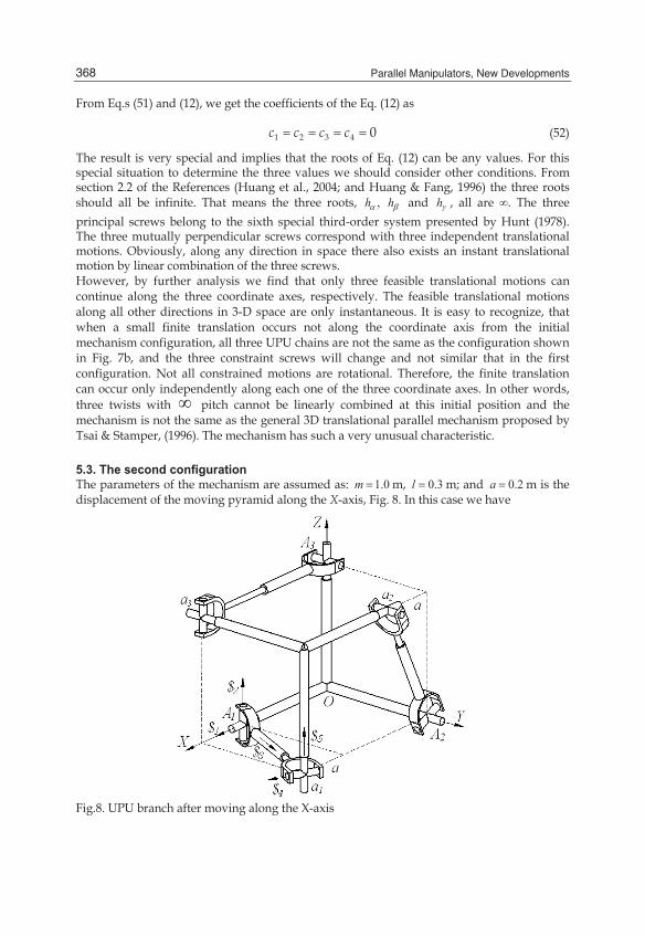
5.3. The second configuration The parameters of the mechanism are assumed as: 1.0m = m, 0.3l = m; and 0.2a = m is the displacement of the moving pyramid along the X-axis, Fig. 8. In this case we have
Fig.8. UPU branch after moving along the X-axis

Principal Screws and Full-Scale Feasible Instantaneous Motions of Some 3-DOF Parallel Manipulators
369
[ ]⎡ ⎤⎢ ⎥′ = −⎢ ⎥⎢ ⎥⎣ ⎦
0 0 00.00567188 0.170156 0.03448280.170156 0.0567188 1.03448
G
[ ]− −⎡ ⎤⎢ ⎥= −⎢ ⎥
−⎢ ⎥⎣ ⎦
0.0567188 0.170156 1.034480.850782 0.0283594 0.172414
0.0351657 1.05497 0.213793G (53)
Substituting [ ]G and [ ]G′ into the Eq. (8) and according to the Eq. (10), we have
= =11 12 13
21 22 23
31 32 33
0a a a
D a a aa a a
(54)
Expanding and solving the equation, we have
α
β
γ
== −= − × 17
5.65.62.16318 10
hhh
(55)
where one is infinite, the other two are finite values with opposite signs. Therefore any screw in the screw system is the linear combination of the three principal screws and its pitch is inside the scope, − ≤ ≤5.6 5.6h . Three principal kinematic screws are
( )( )( )
α
β
γ
=
= − −=
0 1.0 1.0; 88.4053 5.0 6.2 / 20 1.0 1.0; 71.7085 5.0 6.2 / 20 0 0; 1 0 0
$$$
(56)
and the vector equations of three axes are
( )( )( )
α
β
γ
× =
× =
× =
88.4053 5 6.2 / 2
71.7085 5 6.2 / 2
0 0 0
T
T
T
r S
r S
r S
(57)
where αS , βS and γS are three direction vectors of the three principal screws. Comparing
with Eq. (15) in Reference Huang et al., (2004), the three screws in that Eq.(15) are just the linear combination of the three principle screws in Eq. (56). That means the result is correct and proved mutually. This system belongs to a third special three-system screw. When different h value is substituted into Eq. (10), we may obtain different quadratic equation. Giving one set of input ( )1u w , the corresponding pitch of output motion is
shown in Fig.9. Figure 9 illustrates the full-scale feasible instantaneous motion at that moment.

Parallel Manipulators, New Developments
370
We know that each pitch of the screw determines a quadratic equation, Eq. (10). Here all quadratic equations degenerate into a pair of intersecting straight lines, when h lies within the range − < <5.6 5.6h ; It is because that two invariants of all the quadratic equations, Eq. (10), satisfy D = 0 and δ < 0. Similarly, when h = 5.6 and h = -5.6 both quadratic equations collapse into two pairs of superposed straight lines, they are respectively
=u w
+ =0.173127 0.173127 0.0679061u w (58)
The quadratic equation collapses into a point which is just the intersecting point of all the straight lines, as shown in Fig. 9, when γ= = − × = −∞172.16381 10h h . Fig. 9 illustrates the finite-and-infinite pitch graph of the third special three-system screw including the finite pitches in the scope from -5.6 to 5.6 and an infinite pitch. Each point in the figure indicates the relation between the input ( )1u w and the output pitch, h. It is necessary to point out that, for a six-DOF mechanism, infinite pitches of its infinite feasible instant motions distribute in an infinite scope ( )−∞ ∞ , but for this 3-UPU mechanism its infinite possibility is only in a limited scope (-5.6, 5.6) plus a point with infinite pitch value. From Fig. 9, we can find that all the straight lines pass through a common point, which is a very special point. The pitch values of all the straight lines are finite, but at the special point, the pitch suddenly becomes infinite
-3 -2 -1 0 1 2 3u
-3
-2
-1
0
1
2
3w-5.6 -5.0 -1.01.0 5.0
5.6
5.0
1.0-1.0
-5.0
-1.01.0
5.0
5.05.61.0-1.0 -5.0
-5.0
-5.6
0.0
0.00.0
0.0
Fig. 9. The Pitch of the Twist at the Second Configuration of 3-TPT Mechanism.
6. Future research Based on this principle many three-degrees of freedom parallel mechanisms need to be further analyzed.

Principal Screws and Full-Scale Feasible Instantaneous Motions of Some 3-DOF Parallel Manipulators
371
7. Conclusions This chapter presents a study on the full-scale instant twists motions of 3-DOF parallel manipulators. The study is of extremely benefit to understand and correctly apply a mechanism. It is based on principal screws of the screw system. The key problem is to derive three principal screws from a given 3-DOF mechanism. It needs to set the relation between the pitches of the principal screws and the three linear inputs of the mechanism. In this chapter, the effective method to identify the principal screws of a third-order screw system of 3-DOF mechanisms is presented. For obtaining the principal screws there introduce two methods, the quadratic curve degenerating theory and quadric degenerating theory. Besides, the imaginary-mechanism influence coefficient principle is also used. In the following sections two mechanisms are discussed using the principle. Analyzing the full-scale screws the planar representations of pitches and the spatial distributions of the axes are illustrated. It is necessary to conclude that the special 3-UPU mechanism has some exceptional interesting characteristics. At the initial configuration, the moving pyramid can continually translate along the X- or Y- or Z-axis, however, for all other directions the translational freedom is only instantaneous. At a general configuration, all the straight lines with different pitch pass through a common point, a very special point. The pitch values of all the straight lines are finite, at the intersecting point, however, the pitch is infinite.
8. Acknowledgement The research work reported here is supported by NSFC under Grant No. 59575043 and 50275129.
9. References Ball, R.S. (1900). The Theory of Screws. England: Cambridge University Press. Clavel, R. (1988). DELTA, A fast robot with parallel geometry, Proc. of the Int. Symp. on
Industrial Rob. Switzerland, pp. 91-100. Di Gregorio, R. et al.(1999). Influence of leg flexibility on the kinetostatic behaviour of a 3-
DOF fully-parallel manipulator, Proceedings of 10th World Congress on the Theory of Machine and Mechanisms, June .20-24, Oulu, Finland. 3, pp. 1091-1098.
Fang, Y. F. & Huang, Z. (1998). Analytical Identification of the Principal Screw of the Third Order Screw System. Mech.& Mach. Theory. 33(7), 987-992.
Gibson, C. G. & Hunt, K. H. (1990 a). Geometry of Screw Systems-1 screws Genesis and Geometry. Mech.& Mach. Theory. 25(1) 1-10.
Gibson, C. G. & Hunt, K. H. (1990 b). Geometry of Screw Systems-2 Classification of Screw Systems. Mech.& Mach. Theory. 25(1), 11-27.
Gosselin, C. M. & Angeles, J. (1988). The optimum kinematic design of a planar three-DOH parallel manipulator, Transactions of the ASME Journal Mech Trans. Autom. Des., 110 (1), 35-41.
Gosselin, C. M. & Angeles, J.(1989). The optimum kinematic design of a spherical three-degree-of-freedom parallel manipulator, Transactions of the ASME Journal Mech. Trans. Autom. Des., 111 (2), 202-207.

Parallel Manipulators, New Developments
372
Huang, Z. (1985). Modeling Formulation of 6-DOF multi-loop Parallel Manipulators, Part-1: Kinematic Influence Coefficients, Proc. of the 4th IFToMM International Symposium on Linkage and Computer Aided Design Methods, Bucharest, Romania, Vol. II-1, 155-162
Huang, Z. & Fang, Y.F. (1996). Kinematic Characteristics Analysis of 3-DOF In-Parallel Actuated Pyramid Mechanisms. Mech. & Mach. Theory, 31(8), 1009-1018.
Huang, Z.; Li, S.H. & Zuo, R.G. (2004). Feasible instantaneous motions and kinematic characteristics of a special 3-DOF 3-UPU parallel manipulator. Mechanism and Machine Theory, 2004, 39(9), 957-970
Huang, Z.; Tao, W. S. & Fang, Y. F. (1996). Study on the Kinematic Characteristics of 3-DOF Parallel Actuated Platform Mechanisms. Mech. & Mach. Theory, 31(8), 999-1007.
Huang, Z; Zhao, Y.S. & Zhao, T.S., Advanced Spatial Mechanism,Beijing, Higher Education Press, 2006 (in Chinese)
Huang, Z. & Wang, H. B. (1992). Dynamic Force Analysis of n-DOF Multi-Loop Complex Spatial Mechanism. Mechanism and Machine Theory, 27(1), 97-105.
Huang, Z. & Wang, J. (2001). Identification of principal screws of 3-DOF parallel manipulators by quadric degeneration. Mechanism and Machine Theory, Vol 36(8), 893-911
Huang, Z. & Wang, J. (2002). Huang Z, Wang J, Analysis of Instantaneous Motions of Deficient-Rank 3-RPS Parallel Manipulators. Mechanism and Machine Theory, 37(2):229-240
Hunt, K. H. (1978). Kinematic Geometry of Mechanisms. Oxford University Press, Hunt, K. H. (1983). Structural Kinematics of In-Parallel-Actuated Robot Arms. Trans. ASME
J. Mech. Trans. Auto. Des., 105(4), 705-712. Lee, K.M. & Shah, D.K. (1988). Kinematic analysis of a three-degree-of-freedom parallel
actuated manipulator. IEEE Trans. Robotics Autom., 4 (3), 354-360. Parkin, J. A. (1990). Co-ordinate Transformations of Screws with Application to Screw
Systems and Finite Twists. Mech. & Mach. Theory, 25(6), 689-699. Song, S.M. & Zhang, M.D. (1995). A Study of Reactional Force Compensation Based on
Three-Degree-of Freedom Parallel Platforms. J. Robotic System, 12 (12), 783-794. Thomas, M. & Tesar, D.(1983). Dynamic modeling of serial manipulator arms. J. Dyn. Sys.
Meas. Cont., 104(9), 218-227. Tsai, M. J. & Lee, H. W. (1993). On the Special Bases of Two-and-Three Screw Systems,
Trans. of the ASME J Mech Design, 115 540-546. Tsai, L. W. Stamper, R. (1996). A parallel manipulator with only translational degrees of
freedom. ASME 96-DETC-MECH-112. Irvine(CA), USA,. Waldron, K. J.; Raghavan, M. & Roth, B. (1989). Kinematics of a hybird series–parallel
manipulation system. Transactions of the ASME Journal Mech Trans. Autom. Des., 111, 211-221.
Yan, J. & Huang, Z. (1985). Kinematic Analysis of Multi-Loop Spatial Mechanism, Proc. Of the 4th IFToMM International Symposium on Linkage and Computer Aided Design Method, Bucharest, Vol.2-2, 439-446
Zhang, W. X. & Xu, Z. C. (1998). Algebraic Construction of the Three-System of Screws. Mech. Mach. Theory, 33 (7), 925-930.
Zhao, T.S.; Zhao, Y.S. & Huang, Z. (1999). Physical and Mathematical Conditions of Existence of Axes about Which Platform of Deficient-Rank Parallel Robots Can Rotate continuously. Robot, 21(5), 347-351 (in Chinese)

© 2008 The Author(s). Licensee IntechOpen. This chapter isdistributed under the terms of the Creative Commons Attribution-NonCommercial-ShareAlike-3.0 License, which permits use,distribution and reproduction for non-commercial purposes,provided the original is properly cited and derivative works buildingon this content are distributed under the same license.