Embed Size (px)
Citation preview

Server
PRIMERGY S40-DFCapacity Extension
Xenia FierleySiemens Nixdorf Informationssysteme AG ICP CS PS QM 381730 Münchene-mail: email: [email protected].: (089) 636-47896Fax: 0 700 / 372 00000U41100-J-Z156-1-74Sprachen: En
Edition May 2001

Comments… Suggestions… Corrections…The User Documentation Department would like to know your opinion on this manual. Your feedback helps us to optimize our documentation to suit your individual needs.
Fax forms for sending us your comments are included at the back of the manual.
There you will also find the addresses of the relevant User Documentation Department
Copyright and Trademarks
Copyright © 2001 Fujitsu Siemens Computers GmbH.
All rights reserved.Delivery subject to availability; right of technical modifications reserved.
All hardware and software names used are trademarks of their respective manufacturers.
This manual was produced bycognitas. Gesellschaft für Technik-Dokumentation mbHwww.cognitas.de
This manual is printed on paper treated with chlorine-free bleach.

German
English


Contents1 PRIMERGY S40-DF capacity extension . . . . . . . . . . . . . 11.1 Target group . . . . . . . . . . . . . . . . . . . . . . . . . . . . 21.2 Notational conventions . . . . . . . . . . . . . . . . . . . . . . . 21.3 Important notes . . . . . . . . . . . . . . . . . . . . . . . . . . 31.3.1 Notes on safety . . . . . . . . . . . . . . . . . . . . . . . . . . 31.3.2 ESD label . . . . . . . . . . . . . . . . . . . . . . . . . . . . . 31.3.3 Notes on transportation . . . . . . . . . . . . . . . . . . . . . . 41.4 Converting the PRIMERGY S40-DF . . . . . . . . . . . . . . . 51.4.1 Removing and mounting the door . . . . . . . . . . . . . . . . . 81.4.2 Removing and mounting the side or top cover . . . . . . . . . . 91.4.3 Removing and mounting the protective shield . . . . . . . . . . 101.4.4 Converting the internal configuration . . . . . . . . . . . . . . 111.4.5 Installing the LVD extender board . . . . . . . . . . . . . . . . 171.4.6 Connecting the capacity extension . . . . . . . . . . . . . . . 19
Related publications . . . . . . . . . . . . . . . . . . . . . . . . . . . 21
Index . . . . . . . . . . . . . . . . . . . . . . . . . . . . . . . . . . . . 23
U41100-J-Z156-1-74


1 PRIMERGY S40-DF capacity extension
The PRIMERGY S40-DF is the active component in the PRIMERGY S40 family of storage subsystems. The integrated disk array controller allows you to extend storage capacity using additional externally-connected passive PRIMERGY S40-ES storage devices. Two of these so-called “daisy-chain” configurations, i.e., with one or three PRIMERGY S40-ES units, are supported (see also the chapter on “Configurations” in the PRIMERGY S40-DF Operating Manual).
In order to use a configuration with three external PRIMERGY S40-ES units, you will need the 1-channel version of the PRIMERGY S40-DF.
This manual contains conversion instructions which describe the steps required to prepare a PRIMERGY S40-DF (3-channel version) for capacity expansion with three PRIMERGY S40-ES subsystems.
For more assistance in understanding the details here, see also the operating instructions for the “PRIMERGY S40-DF Storage Subsystem”. Further relevant information can be found in the manual “Safety, Warranty and Ergonomy“ (see section “Related publications” on page 21).
U41100-J-Z156-1-74 1

2 U41100-J-Z156-1-74
Target group PRIMERGY S40-DF capacity extension
1.1 Target group
These conversion instructions are intended for those who are responsible for installing hardware and for ensuring that the system runs smoothly (service personnel, technicians and technical specialists).
You will therefore need to be familiar with the hardware and data transmission concepts to understand the various activities described.
1.2 Notational conventions
bold type Used for emphasis in the body of the text
“quotation marks” Used for references to other chapters, sections or manuals
Ê Identifies an action that you need to take
V CAUTION! Indicates a warning which, if not observed, could jeopardize your health or the proper functionality of the system
I Indicates additional information, notes and tips
Table 1: Notational conventions

PRIMERGY S40-DF capacity extension Important notes
1.3 Important notes
1.3.1 Notes on safety
Please observe all the safety instructions given in the documentation of the PRIMERGY S40-DF as well as the following notes:
V CAUTION!
● The actions described here should only be performed by technicians, service personnel or technical specialists. Any failure to observe the guidelines in this manual could expose the user to considerable risks (electric shock, fire hazards) and could also damage the equipment. Note that any unauthorized opening of the device will result in the invalidation of the warranty and exclusion from all liability.
● Make sure that no objects (such as bracelets or paper clips) or liquids fall into the device, as this may result in an electric shock or a short circuit.
● Before opening the unit, switch off the device and then pull out the power plugs.
● Note that switching off the device does not disconnect it from the power supply. To ensure that the device is fully disconnected from the power supply, you must pull out the power plugs.
1.3.2 ESD label
Systems and components which might be damaged by electrostatic discharge (ESD) may be marked with the following label:
Figure 1: Label indicating ESD-sensitive devices
U41100-J-Z156-1-74 3

4 U41100-J-Z156-1-74
Important notes PRIMERGY S40-DF capacity extension
When handling ESD-sensitive devices, it is essential that you observe the following guidelines:
Ê You must electrostatically discharge yourself (e.g. by touching a grounded object) before handling such components.
Ê Any devices or tools that are used must be free from electrostatic charge.
Ê Pull out the power plug before mounting or dismounting ESD-sensitive devices.
Ê ESD-sensitive devices should only be held at the edges.
Ê Do not touch any pins, connectors or circuits on an ESD-sensitive device.
Ê When installing boards, make sure that you use an electrostatic wrist-band or some other suitable grounding cable that connects you to the external housing of the system unit.
Ê Place all components on a pad which is free from electrostatic charge.
I For detailed instructions on handling ESD-sensitive modules, please read the German documentation “Richtlinie zur Handhabung von elektrostatisch gefährdeten Bauelementen und Baugruppen (EGB)" or “ITS-Rundschreiben Nr. 4/95".
I An ESD kit can be ordered from SIEMENS sales or an authorized distributor under the order number 8501 and stock-no. 06431046.
1.3.3 Notes on transportation
I The storage subsystem should always be transported only in its original packaging or in some other suitable packaging that protects it against shock or impact. It should only be unpacked at the deployment site.
If you need to physically lift or transport the storage subsystem, ask someone to assist you.

PRIMERGY S40-DF capacity extension Converting the PRIMERGY S40-DF
1.4 Converting the PRIMERGY S40-DF
In order to install expanded storage capacity using one or three PRIMERGY S40-ES storage subsystems, you will need the corresponding conversion kit.
This conversion kit contains the following components:
– an LVD extender board (3-channel version and 1-channel version)
– an OLR/STM-LVD flat ribbon cable (3-channel version)
Proceed as follows:
Ê Unpack all the components.
Ê Check the contents of the package for any visible damage resulting from transportation.
Ê Verify that the delivered components match those listed in the delivery note.
If you detect any damage resulting from transportation or any deviations inthe supplied contents and the delivery note, please contact your vendor immediately!
Floorstand and stackable models
Ê Make sure that the storage subsystem is freely accessible from the front and the back.
Ê Switch off the storage subsystem and disconnect it from the power supply.
V CAUTION!
Note that switching off the device does not disconnect it from the power supply. To ensure that the device is fully disconnected from the power supply, you must pull out the power plugs.
Ê Remove the door (see section “Removing and mounting the door” on page 8).
Ê Remove the left side cover for the floorstand model or the top cover for the stackable model (see section “Removing and mounting the side or top cover” on page 9).
Ê Remove the protective shield for the SCSI area of the storage subsystem (see section “Removing and mounting the protective shield” on page 10).
U41100-J-Z156-1-74 5

Converting the PRIMERGY S40-DF PRIMERGY S40-DF capacity extension
Ê Convert the internal configuration of the storage subsystem from a 3-channel configuration to a 1-channel configuration (see section “Converting the internal configuration” on page 11).
Ê Mount the protective shield for the SCSI area (see section “Removing and mounting the protective shield” on page 10).
Ê Replace the side or top cover (see section “Removing and mounting the side or top cover” on page 9).
Ê Replace the door and close the storage subsystem (see section “Removing and mounting the door” on page 8).
Ê Install the LVD extender board (see section “Installing the LVD extender board” on page 17).
Ê Connect the three PRIMERGY S40-ES units to the corresponding SCSI ports on the LVD extender board (see section “Connecting the capacity extension” on page 19).
I Note that if the PRIMERGY S40-ES is connected, the system parameters PWR ON/OFF BY BUTTON and PWR ON/OFF BY CAN must be set to DISABLE.
Ê Connect the PRIMERGY S40-DF and the three PRIMERGY S40-ES units to the power supply.
Ê Connect the PRIMERGY S40-DF to the PRIMERGY server.
Rack model
Ê Make sure that the storage subsystem is freely accessible from the front and the back.
Ê Switch off the storage subsystem and disconnect it from the power supply.
V CAUTION!
Note that switching off the device does not disconnect it from the power supply. To ensure that the device is fully disconnected from the power supply, you must pull out the power plugs.
Ê Loosen the four knurled screws and pull out the storage subsystem from the rack.
6 U41100-J-Z156-1-74

PRIMERGY S40-DF capacity extension Converting the PRIMERGY S40-DF
Ê Remove the rack storage subsystem from the rack.
V CAUTION!
For removing the device from the rack, ask someone to assist you.For more assistance, see the operating instructions for the “PRIMERGY S40-DF Storage Subsystem” (see section “Related publications” on page 21).
Ê Remove the protective shield for the SCSI area of the storage subsystem (see section “Removing and mounting the protective shield” on page 10).
Ê Convert the internal configuration of the storage subsystem from a 3-channel configuration to a 1-channel configuration (see section “Converting the internal configuration” on page 11).
Ê Mount the protective shield for the SCSI area (see section “Removing and mounting the protective shield” on page 10).
Ê Insert the storage subsystem back in the rack and fasten it with the four knurled screws.
Ê Install the LVD extender board (see section “Installing the LVD extender board” on page 17).
Ê Install the three PRIMERGY S40-ES units in the rack with the help of the operating instructions for the “PRIMERGY S40-BS/-ES Storage Subsystem“.
Ê Connect the three PRIMERGY S40-ES units to the corresponding SCSI ports on the LVD extender board (see section “Connecting the capacity extension” on page 19).
I Note that if the PRIMERGY S40-ES is connected, the system parameters PWR ON/OFF BY BUTTON and PWR ON/OFF BY CAN must be set to DISABLE.
Ê Connect the PRIMERGY S40-DF and the three PRIMERGY S40-ES units to the power supply.
Ê Connect the PRIMERGY S40-DF to the PRIMERGY server.
U41100-J-Z156-1-74 7
Converting the PRIMERGY S40-DF PRIMERGY S40-DF capacity extension
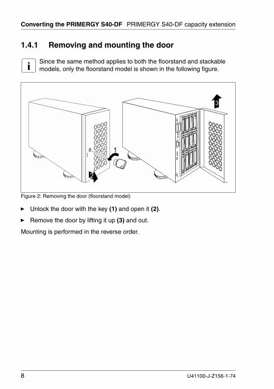
1.4.1 Removing and mounting the door
I Since the same method applies to both the floorstand and stackable models, only the floorstand model is shown in the following figure.
Figure 2: Removing the door (floorstand model)
Ê Unlock the door with the key (1) and open it (2).
Ê Remove the door by lifting it up (3) and out.
Mounting is performed in the reverse order.
�
�
�
8 U41100-J-Z156-1-74

PRIMERGY S40-DF capacity extension Converting the PRIMERGY S40-DF
1.4.2 Removing and mounting the side or top cover
Figure 3: Removing the side cover (floorstand model)
Figure 4: Removing the top cover (stackable model)
Ê Press the two buttons (1) and remove the left side cover or the top cover (2).
Mounting is performed in the reverse order.
�
�
�
�
�
�
U41100-J-Z156-1-74 9

Converting the PRIMERGY S40-DF PRIMERGY S40-DF capacity extension
1.4.3 Removing and mounting the protective shield
I Since the same method applies to all housing models, only the rack-mounted model is shown in the following figures.
Figure 5: Unlocking the protective shield
Ê Unlock the protective shield for the SCSI area by turning the lever (figure 5) and remove the protective shield (figure 6).
Figure 6: Removing the protective shield
10 U41100-J-Z156-1-74

PRIMERGY S40-DF capacity extension Converting the PRIMERGY S40-DF
Mounting is performed in the reverse order. For mounting, the four metal tabs (1) must first be inserted into the corresponding openings (2) (see figure 7).
Figure 7: Mounting the protective shield
1.4.4 Converting the internal configuration
V CAUTION!
The actions described here should only be performed by technicians, service personnel or technical specialists. Any failure to observe the guidelines in this manual could expose the user to considerable risks (electric shock, fire hazards) and could also damage the equipment. Note that any unauthorized opening of the device will result in the invalidation of the warranty and exclusion from all liability.
In order to install a capacity expansion with three PRIMERGY S40-ES units, you will need to first change the internal cabling of the PRIMERGY S40-DF from a 3-channel configuration (figure 8 on page 12) to a 1-channel configuration (figure 12 on page 16).
The same method applies to all housing models.
�
�
�
�
U41100-J-Z156-1-74 11

Converting the PRIMERGY S40-DF PRIMERGY S40-DF capacity extension
Figure 8: Internal cabling for 3-channel configuration - initial state
��
����
� � � � � � � � � � � �
� � � � � � � � � � � �
�
�
�
� � �
� � � �� � �� � � � �
��
� � �
� � �
� � ! " � � � � "� � � � � � � �
� � � �� � �� � � � �
� � � �� � �� � � � �
12 U41100-J-Z156-1-74

PRIMERGY S40-DF capacity extension Converting the PRIMERGY S40-DF
Figure 9: Removing the STM-LVD modules
Ê Pull out the SCSI addressing cable (1) from the connection ports on the STM-LVD modules of the SCSI drive cages 2 and 3.
I For cage 1, the STM-LVD module remains connected with the SCSI addressing cable on the backplane.
Ê Remove the STM-LVD modules (2) of the SCSI drive cages 2 and 3. Removing the STM-LVD module frees the SCSI connector X1 on the SCSI backplane (see also figure 12 on page 16).
� � � �
�
� � � �
� � � ��
U41100-J-Z156-1-74 13

Converting the PRIMERGY S40-DF PRIMERGY S40-DF capacity extension
Figure 10: Controller backplane: SCSI ports - initial state
Ê Pull out the SCSI connection cable for cage 1 (3.1) from the controller backplane (see also figure 8 on page 12) and connect it to the freed SCSI connector X1 (see figure 12 on page 16) on the backplane of cage 2 (see figure 11 on page 15).
Ê Pull out the SCSI connection cable for cage 2 (3.2) from the controller backplane (see also figure 8 on page 12) and connect it to the freed SCSI connector X1 (see figure 12 on page 16) on the backplane of cage 3 (see figure 11 on page 15).
Ê Pull out the SCSI connection cable for cage 3 (3.3) from the controller backplane (see also figure 8 on page 12) and connect it to the first SCSI port on the backplane of the controller (see figure 11 on page 15 and figure 12 on page 16).
� � � � � �� � �
14 U41100-J-Z156-1-74

PRIMERGY S40-DF capacity extension Converting the PRIMERGY S40-DF
Figure 11: 1-Setting up the channel configuration
Ê Connect the supplied OLR/STM-LVD flat ribbon cable as follows:
– Connect the common end (4) of the two cable strands with the connector X5 on the STM-LVD module on the backplane of cage 1 (see also figure 12 on page 16).
– Connect the shorter strand (5) with the connector X4 on the backplane of cage 2 (see also figure 12 on page 16).
– Connect the longer strand (6) with the connector X4 on the backplane of cage 3 (see also figure 12 on page 16).
This cable determines the SCSI addresses of the drives located in the SCSI cages 2 and 3 in the 1-channel configuration.
� � � �
� � �
� � � �
� � � �� � �
� � �
#
$
�
U41100-J-Z156-1-74 15

Converting the PRIMERGY S40-DF PRIMERGY S40-DF capacity extension
Figure 12: Internal cabling for 1-channel configuration - final state
��
����
� � � � � � � � � � � �
% #
% �
% � % �
% �
�
�
�
� � � � � � � � � � � �
� � ! " � � � � " � � � � � � � �
�
#
�� � �
� � �
� � �
$� � � �� � �� � � � �
16 U41100-J-Z156-1-74

PRIMERGY S40-DF capacity extension Converting the PRIMERGY S40-DF
1.4.5 Installing the LVD extender board
The insertion slot for the LVD extender board is on the back of the storage subsystem and is covered by a plate.
If you need further assistance, refer to the operating instructions for the “PRIMERGY S40-DF Storage Subsystem“.
Figure 13: Removing the plate
Ê Loosen the two screws (1) and remove the plate covering the insertion slot (2).
�
�
�
U41100-J-Z156-1-74 17

Converting the PRIMERGY S40-DF PRIMERGY S40-DF capacity extension
V CAUTION!
Please observe the notes pertaining to the ESD label in the section “Important notes” on page 3.
Figure 14: Installing the LVD extender board
V CAUTION!
Before installing the board, make sure that all DIP switches are set to ON.
Ê Insert the board into the free slot (1).
Ê Fasten the LVD extender board with the two knurled screws (2).
�
�
�
18 U41100-J-Z156-1-74

PRIMERGY S40-DF capacity extension Converting the PRIMERGY S40-DF
1.4.6 Connecting the capacity extension
Figure 15: PRIMERGY S40-DF with capacity extension
Ê Connect each of the three PRIMERGY S40-ES subsystems (SCSI interface channel 0) using a SCSI cable to one of the three SCSI ports on the LVD extender of the PRIMERGY S40-DF.
For further assistance in understanding these connections, see also the operating instructions for the “PRIMERGY S40-BS/-ES Storage Subsystem” and the “PRIMERGY S40-DF Storage Subsystem“, respectively.
PRIMERGY S40-ES
1 channelversion
PRIMERGY S40-ES
1 channelversion
PRIMERGY S40-ES
1 channelversion
DA
C 9
60 F
L
FC
L-A
dp.
LVD extender
FC
L-A
dp.
0
2 1 3
PRIMERGY S40-DF
1 channelversion
U41100-J-Z156-1-74 19


Related publicationsPlease apply to your local office for ordering the manuals.
[1] Safety, Guarantee and Ergonomics
[2] 19-Inch Rack for PRIMERGY and RM Systems Technical Manual
[3] PRIMERGY S40-DFStorage Subsystem Operating Manual
[4] PRIMERGY S40-BS/ESStorage Subsystem Operating Manual
U41100-J-Z156-1-74 21


Index
Ccapacity expansion 1, 5, 11configurationconverting the internal configu-ration 11
conversion kit 5
EESD label 3
LLVD extender board
installing 17
Mmounting/removing the protective
shield 10mounting/removing the side cover 9
Nnotational conventions 2notes on safety 3
OOLR/STM-LVD flat ribbon cable 15
Rremoving/mounting the door 8
SSCSI addressing cable 13SCSI ports
final state 16initial state 14
STM-LVD modulesremoving 13
Ttarget group 2transportation 4
U41100-J-Z156-1-74 23


Comments on PRIMERGY S40-DFCapacity Extension
U41100-J-Z156-1-74
CommentsSuggestionsCorrections
✁
Submitted by
Fujitsu Siemens Computers GmbH User Documentation 81730 MünchenGermany
Fax: 0 700 / 372 00000
email: [email protected]://manuals.fujitsu-siemens.com


Information on this document On April 1, 2009, Fujitsu became the sole owner of Fujitsu Siemens Compu-ters. This new subsidiary of Fujitsu has been renamed Fujitsu Technology So-lutions.
This document from the document archive refers to a product version which was released a considerable time ago or which is no longer marketed.
Please note that all company references and copyrights in this document have been legally transferred to Fujitsu Technology Solutions.
Contact and support addresses will now be offered by Fujitsu Technology So-lutions and have the format …@ts.fujitsu.com.
The Internet pages of Fujitsu Technology Solutions are available at http://ts.fujitsu.com/... and the user documentation at http://manuals.ts.fujitsu.com.
Copyright Fujitsu Technology Solutions, 2009
Hinweise zum vorliegenden Dokument Zum 1. April 2009 ist Fujitsu Siemens Computers in den alleinigen Besitz von Fujitsu übergegangen. Diese neue Tochtergesellschaft von Fujitsu trägt seit-dem den Namen Fujitsu Technology Solutions.
Das vorliegende Dokument aus dem Dokumentenarchiv bezieht sich auf eine bereits vor längerer Zeit freigegebene oder nicht mehr im Vertrieb befindliche Produktversion.
Bitte beachten Sie, dass alle Firmenbezüge und Copyrights im vorliegenden Dokument rechtlich auf Fujitsu Technology Solutions übergegangen sind.
Kontakt- und Supportadressen werden nun von Fujitsu Technology Solutions angeboten und haben die Form …@ts.fujitsu.com.
Die Internetseiten von Fujitsu Technology Solutions finden Sie unter http://de.ts.fujitsu.com/..., und unter http://manuals.ts.fujitsu.com finden Sie die Benutzerdokumentation.
Copyright Fujitsu Technology Solutions, 2009