Embed Size (px)
Citation preview

Draft Specification for PowerLine Intelligent Metering Evolution
Draft Specification for
PoweRline Intelligent Metering Evolution
Prepared by the PRIME Alliance Technical Working Group
This document is an approved draft specification. As such, it is subject to change. Prior to the full or partial adoption of this document by any standards development organization, permission must be obtained from the PRIME Alliance.
Abstract:
This is a complete draft specification for a new OFDM-based power line communications for the provision of all kinds of Smart Grid services over electricity distribution networks. Both PHY and MAC layers according to IEEE conventions, plus a Convergence layer, are described in the Specification.
R1.3.6 page PRIME Alliance TWG
1
2
45
678
9
10111213141516
17
18
192021

Draft Specification for PowerLine Intelligent Metering Evolution
Content Table
Content Table..................................................................................................................................................2
List of Figures...................................................................................................................................................8
List of Tables..................................................................................................................................................12
1 Introduction............................................................................................................................................18
1.1 Scope..............................................................................................................................................18
1.2 Overview.........................................................................................................................................18
1.3 Normative references.....................................................................................................................18
1.4 Document conventions...................................................................................................................20
1.5 Definitions......................................................................................................................................20
1.6 Abbreviations and Acronyms..........................................................................................................22
2 General Description................................................................................................................................26
2.1 Introduction....................................................................................................................................26
2.2 General description of the architecture..........................................................................................26
3 Physical layer..........................................................................................................................................27
3.1 Introduction....................................................................................................................................27
3.2 Overview.........................................................................................................................................27
3.3 PHY parameters..............................................................................................................................28
3.4 Preamble, header and payload structure.......................................................................................30
3.4.1 Preamble.................................................................................................................................30
3.4.2 Pilot structure.........................................................................................................................30
3.4.3 Header and Payload................................................................................................................32
3.5 Convolutional encoder....................................................................................................................33
3.6 Scrambler........................................................................................................................................34
3.7 Interleaver......................................................................................................................................34
3.8 Modulation.....................................................................................................................................35
3.9 Electrical specification of the transmitter.......................................................................................37
R1.3.6 page PRIME Alliance TWG
22
23
24
25
26
27
28
29
30
31
32
33
34
35
36
37
38
39
40
41
42
43
44
45
46
47
48

Draft Specification for PowerLine Intelligent Metering Evolution
3.9.1 General...................................................................................................................................37
3.9.2 Transmit PSD...........................................................................................................................37
3.9.3 Error Vector Magnitude (EVM)...............................................................................................39
3.9.4 Conducted disturbance limits.................................................................................................39
3.10 PHY service specification................................................................................................................39
3.10.1 General...................................................................................................................................39
3.10.2 PHY Data plane primitives.......................................................................................................40
3.10.3 PHY Control plane primitives..................................................................................................43
3.10.4 PHY Management primitives..................................................................................................50
4 MAC layer...............................................................................................................................................56
4.1 Overview.........................................................................................................................................56
4.2 Addressing......................................................................................................................................57
4.2.1 General...................................................................................................................................57
4.2.2 Example of address resolution................................................................................................58
4.2.3 Broadcast and multicast addressing.......................................................................................60
4.3 MAC functional description............................................................................................................60
4.3.1 Service Node start-up.............................................................................................................60
4.3.2 Starting and maintaining Subnetworks...................................................................................61
4.3.3 Channel Access.......................................................................................................................62
4.3.4 Tracking switches and peers...................................................................................................67
4.3.5 Switching................................................................................................................................68
4.3.6 Direct connections..................................................................................................................72
4.3.7 Packet aggregation.................................................................................................................77
4.3.8 Security...................................................................................................................................78
4.4 MAC PDU format............................................................................................................................82
4.4.1 General...................................................................................................................................82
4.4.2 Generic MAC PDU...................................................................................................................82
R1.3.6 page PRIME Alliance TWG
49
50
51
52
53
54
55
56
57
58
59
60
61
62
63
64
65
66
67
68
69
70
71
72
73
74
75
Draft Specification for PowerLine Intelligent Metering Evolution
4.4.3 Promotion Needed PDU..........................................................................................................86
4.4.4 Beacon PDU............................................................................................................................87
4.4.5 MAC control packets...............................................................................................................90
4.5 MAC Service Access Point.............................................................................................................111
4.5.1 General.................................................................................................................................111
4.5.2 Service Node and Base Node signalling primitives................................................................113
4.5.3 Base Node signalling primitives............................................................................................121
4.5.4 Service and Base Nodes data primitives...............................................................................122
4.5.5 MAC Layer Management Entity SAPs....................................................................................123
4.6 MAC procedures...........................................................................................................................131
4.6.1 Registration...........................................................................................................................131
4.6.2 Unregistering process...........................................................................................................133
4.6.3 Promotion process................................................................................................................133
4.6.4 Demotion process.................................................................................................................135
4.6.5 Keep-Alive process................................................................................................................136
4.6.6 Connection management.....................................................................................................137
4.6.7 Multicast group management...............................................................................................139
4.6.8 PHY Robustness Management..............................................................................................144
4.6.9 Channel allocation and deallocation.....................................................................................146
4.7 Automatic Repeat Request (ARQ).................................................................................................147
4.7.1 General.................................................................................................................................147
4.7.2 Initial negotiation..................................................................................................................147
4.7.3 ARQ mechanism....................................................................................................................147
4.7.4 ARQ packets switching..........................................................................................................151
5 Convergence layer................................................................................................................................152
5.1 Overview.......................................................................................................................................152
5.2 Common Part Convergence Sublayer (CPCS)................................................................................152
R1.3.6 page PRIME Alliance TWG
76
77
78
79
80
81
82
83
84
85
86
87
88
89
90
91
92
93
94
95
96
97
98
99
100
101
102
Draft Specification for PowerLine Intelligent Metering Evolution
5.2.1 General.................................................................................................................................152
5.2.2 Segmentation and Reassembly (SAR)...................................................................................152
5.3 NULL Service-Specific Convergence Sublayer (NULL SSCS)...........................................................154
5.3.1 Overview...............................................................................................................................154
5.3.2 Primitives..............................................................................................................................154
5.4 IPv4 Service-Specific Convergence Sublayer (IPv4 SSCS)..............................................................155
5.4.1 Overview...............................................................................................................................155
5.4.2 Address resolution................................................................................................................156
5.4.3 IPv4 packet transfer..............................................................................................................158
5.4.4 Segmentation and reassembly..............................................................................................159
5.4.5 Header compression.............................................................................................................159
5.4.6 Quality of Service mapping...................................................................................................159
5.4.7 Packet formats and connection data....................................................................................160
5.4.8 Service Access Point..............................................................................................................166
5.5 IEC 61334-4-32 Service-Specific Convergence Sublayer (IEC 61334-4-32 SSCS)............................170
5.5.1 General.................................................................................................................................170
5.5.2 Overview...............................................................................................................................170
5.5.3 Address allocation and connection establishment...............................................................171
5.5.4 Connection establishment data format................................................................................172
5.5.5 Packet format.......................................................................................................................173
5.5.6 Service Access Point..............................................................................................................173
5.6 IPv6 Service-Specific Convergence Sublayer (IPv6 SSCS)..............................................................175
5.6.1 Overview...............................................................................................................................175
5.6.2 IPv6 Convergence layer.........................................................................................................176
5.6.3 IPv6 Address Configuration...................................................................................................177
5.6.4 IPv6 Packet Transfer.............................................................................................................180
5.6.5 Segmentation and reassembly..............................................................................................180
R1.3.6 page PRIME Alliance TWG
103
104
105
106
107
108
109
110
111
112
113
114
115
116
117
118
119
120
121
122
123
124
125
126
127
128
129
Draft Specification for PowerLine Intelligent Metering Evolution
5.6.6 Compression.........................................................................................................................181
5.6.7 Quality of Service Mapping...................................................................................................181
5.6.8 Packet formats and connection data....................................................................................182
5.6.9 Service access point..............................................................................................................188
6 Management plane..............................................................................................................................194
6.1 Introduction..................................................................................................................................194
6.2 Node management.......................................................................................................................195
6.2.1 General.................................................................................................................................195
6.2.2 PHY PIB attributes.................................................................................................................195
6.2.3 MAC PIB attributes................................................................................................................197
6.2.4 Application PIB attributes.....................................................................................................208
6.3 Firmware upgrade........................................................................................................................209
6.3.1 General.................................................................................................................................209
6.3.2 Requirements and features..................................................................................................209
6.3.3 General Description..............................................................................................................209
6.3.4 Firmware upgrade PIB attributes..........................................................................................211
6.3.5 State machine.......................................................................................................................212
6.3.6 Examples...............................................................................................................................226
6.4 Management interface description..............................................................................................228
6.4.1 General.................................................................................................................................228
6.4.2 Payload format of management information.......................................................................229
6.4.3 NULL SSCS communication profile........................................................................................231
6.4.4 Serial communication profile................................................................................................232
6.5 List of mandatory PIB attributes...................................................................................................232
6.5.1 General.................................................................................................................................232
6.5.2 Mandatory PIB attributes common to all device types.........................................................233
6.5.3 Mandatory Base Node attributes..........................................................................................234
R1.3.6 page PRIME Alliance TWG
130
131
132
133
134
135
136
137
138
139
140
141
142
143
144
145
146
147
148
149
150
151
152
153
154
155
156
Draft Specification for PowerLine Intelligent Metering Evolution
6.5.4 Mandatory Service Node attributes......................................................................................234
Annex A (informative) Examples of CRC.......................................................................................................236
Annex B (normative) EVM calculation..........................................................................................................237
Annex C (informative) Interleaving matrixes................................................................................................238
Annex D (normative) MAC layer constants...................................................................................................240
Annex E (normative) Convergence layer constants......................................................................................241
Annex F (normative) Profiles........................................................................................................................242
F.1 Smart Metering Profile.................................................................................................................242
Annex G (informative) List of frequencies used............................................................................................244
Annex H (informative) Informative...............................................................................................................246
H.1 Data exchange between to IP communication peers...................................................................246
H.2 Joining a multicast group..............................................................................................................248
Annex I (informative) ARQ algorithm...........................................................................................................250
List of authors...............................................................................................................................................251
R1.3.6 page PRIME Alliance TWG
157
158
159
160
161
162
163
164
165
166
167
168
169
170
171
172
Draft Specification for PowerLine Intelligent Metering Evolution
List of Figures
Figure 1 - Reference model of protocol layers used in the OFDM PRIME specification..................................26
Figure 2 - Overview of PPDU processing.........................................................................................................28
Figure 3 - PHY Frame Format.........................................................................................................................28
Figure 4 - Pilot and data subcarrier allocation (OFDM symbols vs subcarriers)..............................................31
Figure 5 - Pilot and data subcarrier frequency allocation inside the header..................................................31
Figure 6 - LFSR for use in Pilot sequence generation......................................................................................32
Figure 7 - PPDU: header and payload (bits transmitted before encoding).....................................................32
Figure 8 - Convolutional encoder...................................................................................................................33
Figure 9 - LFSR for use in the scrambler block................................................................................................34
Figure 10 - DBPSK, DQPSK and D8PSK mapping.............................................................................................35
Figure 11 - Subcarrier Mapping......................................................................................................................36
Figure 12 – Measurement set up (single-phase)............................................................................................37
Figure 13 – Measurement set up (three-phase).............................................................................................38
Figure 14 – Artificial mains network...............................................................................................................38
Figure 15 – EVM meter (block diagram).........................................................................................................39
Figure 16 – Overview of PHY primitives..........................................................................................................40
Figure 17 – Overview of PHY Control Plane Primitives...................................................................................43
Figure 18 - Service Node states......................................................................................................................56
Figure 19 - Addressing Structure....................................................................................................................58
Figure 20 – Example of address resolution: phase 1......................................................................................58
Figure 21 – Example of address resolution: phase 2......................................................................................59
Figure 22 – Example of address resolution: phase 3......................................................................................59
Figure 23 – Example of address resolution: phase 4......................................................................................60
Figure 24 – Structure of a MAC Frame...........................................................................................................62
Figure 25 – Example of control packet sequencing following a promotion....................................................64
Figure 26 - Flow chart for CSMA-CA algorithm...............................................................................................66
R1.3.6 page PRIME Alliance TWG
173
174
175
176
177
178
179
180
181
182
183
184
185
186
187
188
189
190
191
192
193
194
195
196
197
198
199

Draft Specification for PowerLine Intelligent Metering Evolution
Figure 27 - Switching tables example.............................................................................................................69
Figure 28 - Fill in the switching table..............................................................................................................69
Figure 29 – Directed Connection to an unknown Service Node.....................................................................73
Figure 30 - Example of direct connection: connection establishment to a known Service Node...................75
Figure 31 - Release of a direct connection......................................................................................................76
Figure 32 - Key derivation concept.................................................................................................................79
Figure 33 - Security Profile 1 encryption algorithm........................................................................................82
Figure 34 - Generic MAC PDU format.............................................................................................................83
Figure 35 - Generic MAC header....................................................................................................................83
Figure 36 - Packet structure...........................................................................................................................84
Figure 37 – Packet Header..............................................................................................................................84
Figure 38 - PKT.CID structure..........................................................................................................................84
Figure 39 - Promotion Need MAC PDU...........................................................................................................86
Figure 40 – Beacon PDU structure..................................................................................................................87
Figure 41 – Two transactions without requiring retransmits..........................................................................92
Figure 42 - Transaction with packet loss requiring retransmits......................................................................92
Figure 43 – Duplicate packet detection and elimination................................................................................93
Figure 44 - REG control packet structure........................................................................................................94
Figure 45 - CON control packet structure.......................................................................................................97
Figure 46 - PRO_REQ_S control packet structure.........................................................................................101
Figure 47 - PRO control packet structure.....................................................................................................101
Figure 48 - BSI control packet structure.......................................................................................................103
Figure 49 - FRA control packet structure......................................................................................................104
Figure 50 - CFP control packet structure......................................................................................................105
Figure 51 - ALV Control packet structure......................................................................................................106
Figure 52 - MUL control packet structure.....................................................................................................107
Figure 53 – PHY control packet structure.....................................................................................................109
R1.3.6 page PRIME Alliance TWG
200
201
202
203
204
205
206
207
208
209
210
211
212
213
214
215
216
217
218
219
220
221
222
223
224
225
226
Draft Specification for PowerLine Intelligent Metering Evolution
Figure 54 – SEC control packet structure......................................................................................................110
Figure 55 – Establishment of a Connection..................................................................................................112
Figure 56 – Failed establishment of a Connection........................................................................................112
Figure 57 – Release of a Connection.............................................................................................................112
Figure 58- Transfer of Data...........................................................................................................................112
Figure 59 – Registration process accepted...................................................................................................132
Figure 60 – Registration process rejected....................................................................................................132
Figure 61 – Unregistering process initiated by a Terminal Node..................................................................133
Figure 62 – Unregistering process initiated by the Base Node.....................................................................133
Figure 63 – Promotion process initiated by a Service Node.........................................................................134
Figure 64 – Promotion process rejected by the Base Node..........................................................................135
Figure 65 – Promotion process initiated by the Base Node..........................................................................135
Figure 66 – Promotion process rejected by a Service Node.........................................................................135
Figure 67 – Demotion process initiated by a Service Node..........................................................................136
Figure 68 – Demotion process initiated by the Base Node...........................................................................136
Figure 69 – Connection establishment initiated by a Service Node..............................................................137
Figure 70 – Connection establishment rejected by the Base Node..............................................................138
Figure 71 – Connection establishment initiated by the Base Node..............................................................138
Figure 72 – Connection establishment rejected by a Service Node..............................................................138
Figure 73 – Disconnection initiated by a Service Node.................................................................................139
Figure 74 – Disconnection initiated by the Base Node.................................................................................139
Figure 75 – Successful group join initiated by Base Node.............................................................................140
Figure 76 – Failed group join initiated by Base Node...................................................................................141
Figure 77 – Successful group join initiated by Service Node.........................................................................142
Figure 78 – Failed group join initiated by Service Node................................................................................143
Figure 79 – Leave initiated by the Service Node...........................................................................................144
Figure 80 – Leave initiated by the Base Node...............................................................................................144
R1.3.6 page PRIME Alliance TWG
227
228
229
230
231
232
233
234
235
236
237
238
239
240
241
242
243
244
245
246
247
248
249
250
251
252
253

Draft Specification for PowerLine Intelligent Metering Evolution
Figure 81 – PHY robustness management requested by the Switch Node...................................................145
Figure 82 – PHY robustness management requested by the Service Node..................................................145
Figure 83 – Successful allocation of CFP period............................................................................................146
Figure 84 – Successful channel de-allocation sequence...............................................................................146
Figure 85 – Deallocation of channel to one device results in the change of CFP allocated to another........147
Figure 86 - MAC Data PDU with ARQ subheader..........................................................................................148
Figure 87 - ARQ subheader only with the packet id.....................................................................................148
Figure 88 - ARQ subheader with ARQ.INFO..................................................................................................148
Figure 89 - ARQ.ACK byte fields....................................................................................................................148
Figure 90 - ARQ.WIN byte fields...................................................................................................................148
Figure 91 - ARQ.NACK byte fields.................................................................................................................148
Figure 92 - Example of an ARQ subheader with all the fields present..........................................................149
Figure 93 - Stop and wait ARQ subheader with only packet ID....................................................................150
Figure 94 - Stop and wait ARQ subheader with an ACK................................................................................150
Figure 95 - Stop and wait ARQ subheader without data and with an ACK...................................................150
Figure 96 - Structure of the Convergence layer............................................................................................152
Figure 97 - Segmentation and Reassembly Headers.....................................................................................153
Figure 98 - IPv4 SSCS connection example...................................................................................................156
Figure 99 - Example of IPv6 Connection.......................................................................................................177
Figure 100 - Management plane. Introduction............................................................................................194
Figure 101 - Restarting the Nodes and running the new firmware..............................................................211
Figure 102 - Firmware Upgrade mechanism, state diagram.........................................................................215
Figure 103 - Init Service Node and complete FW image...............................................................................226
Figure 104 - Execute upgrade and confirm/reject new FW version..............................................................227
Figure 105. Get PIB Attribute response.Payload...........................................................................................230
Figure 106 – Data encapsulations for management messages.....................................................................232
R1.3.6 page PRIME Alliance TWG
254
255
256
257
258
259
260
261
262
263
264
265
266
267
268
269
270
271
272
273
274
275
276
277
278
279
280
Draft Specification for PowerLine Intelligent Metering Evolution
R1.3.6 page PRIME Alliance TWG
281
Draft Specification for PowerLine Intelligent Metering Evolution
List of Tables
Table 1 - Frequency and Timing Parameters Of the OFDM PRIME PHY..........................................................28
Table 2 - PHY data rate and packet size parameters, for various modulation and coding schemes...............29
Table 3 - Header Parameters..........................................................................................................................29
Table 4 - Fields associated with PHY Control Plane Primitives........................................................................44
Table 5 - PHY layer management primitives...................................................................................................50
Table 6 - Values of the status parameter in PLME_GET.confirm primitive....................................................55
Table 7 - Broadcast and multicast address.....................................................................................................60
Table 8 - Direct connection example: Node B's Direct switching table...........................................................73
Table 9 - Generic MAC header fields..............................................................................................................83
Table 10 – Packet header fields......................................................................................................................84
Table 11 - Promotion Need MAC PDU fields...................................................................................................86
Table 12 - Beacon PDU fields..........................................................................................................................87
Table 13 - MAC control packet types..............................................................................................................90
Table 14 - REG control packet fields...............................................................................................................94
Table 15 - REG control packet types...............................................................................................................96
Table 16 - CON control packet fields..............................................................................................................97
Table 17 - CON control packet types............................................................................................................100
Table 18 - PRO control packet fields.............................................................................................................101
Table 19 - PRO control packet types.............................................................................................................103
Table 20 - BSI control packet fields...............................................................................................................103
Table 21 - BSI control message types...........................................................................................................104
Table 22 - FRA control packet fields.............................................................................................................104
Table 23 - FRA control packet types.............................................................................................................105
Table 24 - CFP control message fields..........................................................................................................105
Table 25 - CFP control packet types..............................................................................................................106
Table 26 - ALV control message fields..........................................................................................................106
R1.3.6 page PRIME Alliance TWG
1
282
283
284
285
286
287
288
289
290
291
292
293
294
295
296
297
298
299
300
301
302
303
304
305
306
307
308
Draft Specification for PowerLine Intelligent Metering Evolution
Table 27 – Keep-Alive control packet types..................................................................................................107
Table 28 - MUL control message fields.........................................................................................................107
Table 29 – MUL control message types........................................................................................................108
Table 30 – PRM control message fields........................................................................................................109
Table 31 – PRM control message types........................................................................................................110
Table 32 – SEC control message fields..........................................................................................................110
Table 33 – List of MAC primitives.................................................................................................................112
Table 34 – Values of the Answer parameter in MAC_ESTABLISH.response primitive...................................115
Table 35 – Values of the Result parameter in MAC_ESTABLISH.confirm primitive.......................................115
Table 36 – Values of the Reason parameter in MAC_RELEASE.indication primitive.....................................116
Table 37 – Values of the Answer parameter in MAC_RELEASE.response primitive......................................117
Table 38 – Values of the Result parameter in MAC_RELEASE.confirm primitive..........................................117
Table 39 – Values of the Result parameter in MAC_JOIN.confirm primitive................................................119
Table 40 – Values of the Answer parameter in MAC_ESTABLISH.response primitive...................................120
Table 41 – Values of the Result parameter in MAC_LEAVE.confirm primitive..............................................121
Table 42 – Values of the Result parameter in MAC_DATA.confirm primitive...............................................123
Table 43 – Values of the Result parameter in MLME_REGISTER.confirm primitive......................................124
Table 44 – Values of the Result parameter in MLME_UNREGISTER.confirm primitive.................................125
Table 45 – Values of the Result parameter in MLME_PROMOTE.confirm primitive.....................................127
Table 46 – Values of the Result parameter in MLME_DEMOTE.confirm primitive.......................................127
Table 47 – Values of the Result parameter in MLME_RESET.confirm primitive...........................................128
Table 48 – Values of the status parameter in MLME_GET.confirm primitive...............................................129
Table 49 – Values of the status parameter in MLME_LIST_GET.confirm primitive.......................................130
Table 50 – Values of the Result parameter in MLME_SET.confirm primitive................................................131
Table 51 - ARQ fields....................................................................................................................................149
Table 52 - SAR header fields.........................................................................................................................153
Table 53 - SAR Constants..............................................................................................................................154
R1.3.6 page PRIME Alliance TWG
2309
310
311
312
313
314
315
316
317
318
319
320
321
322
323
324
325
326
327
328
329
330
331
332
333
334
335
Draft Specification for PowerLine Intelligent Metering Evolution
Table 54 - Primitive mapping between the Null SSCS primitives and the MAC layer primitives...................154
Table 55 - IPV4 SSCS Table Entry.................................................................................................................158
Table 56 - Mapping IPv4 Precedence to OFDM PRIME MAC priority............................................................159
Table 57 - AR_REGISTER_S message format.................................................................................................160
Table 58 - AR_REGISTER_B message format.................................................................................................161
Table 59 - AR_UNREGISTER_S message format............................................................................................161
Table 60 - AR_UNREGISTER_B message format...........................................................................................161
Table 61 - AR_LOOKUP_S message format...................................................................................................162
Table 62 - AR_LOOKUP_B message format..................................................................................................162
Table 63 - AR_MCAST_REG_S message format............................................................................................162
Table 64 - AR_MCAST_REG_B message format............................................................................................163
Table 65 - AR_MCAST_UNREG_S message format.......................................................................................163
Table 66 - AR_MCAST_UNREG_B message format.......................................................................................163
Table 67 - IPv4 Packet format without negotiated header compression......................................................164
Table 68 - IPv4 Packet format with VJ header compression negotiated.......................................................164
Table 69 - Connection signalling data sent by the initiator...........................................................................165
Table 70 - Connection signaling data sent by the responder........................................................................165
Table 71 - Connection Signalling Data sent by the Service Node..................................................................172
Table 72 - Connection Signalling Data sent by the Base Node......................................................................173
Table 73 – IPv6 convergence layer table entry.............................................................................................180
Table 74 – Mapping Ipv6 precedence to PRIME MAC priority......................................................................181
Table 75 - AR_REGISTERv6_S message format.............................................................................................182
Table 76 - AR_REGISTERv6_B message format.............................................................................................182
Table 77 - AR_UNREGISTERv6_S message format........................................................................................183
Table 78 - AR_UNREGISTERv6_B message format........................................................................................183
Table 79 - AR_LOOKUPv6_S message format...............................................................................................183
Table 80 - AR_LOOKUPv6_B message format...............................................................................................184
R1.3.6 page PRIME Alliance TWG
3336
337
338
339
340
341
342
343
344
345
346
347
348
349
350
351
352
353
354
355
356
357
358
359
360
361
362
Draft Specification for PowerLine Intelligent Metering Evolution
Table 81 - AR_MCAST_REGv6_S message format........................................................................................184
Table 82 - AR_MCAST_REGv6_B message format........................................................................................185
Table 83 - AR_MCAST_UNREGv6_S message format...................................................................................185
Table 84 - AR_MCAST_UNREGv6_B message format...................................................................................185
Table 85 - IPv6 Packet format without negotiated header compression......................................................186
Table 86 - UDP/IPv6 Packet format with LOWPAN_IPHC1 header compression and LOWPAN_NHC..........186
Table 87 - IPv6 Packet format with LOWPAN_IPHC negotiated header compression..................................187
Table 88 - IPv6 Connection signalling data sent by the initiator...................................................................187
Table 89 - IPv6 Connection signalling data sent by the responder...............................................................188
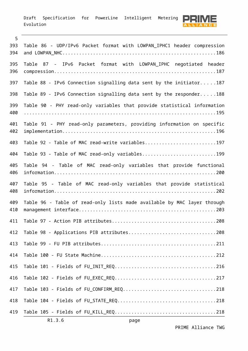
Table 90 - PHY read-only variables that provide statistical information.......................................................195
Table 91 - PHY read-only parameters, providing information on specific implementation..........................196
Table 92 - Table of MAC read-write variables...............................................................................................197
Table 93 - Table of MAC read-only variables................................................................................................199
Table 94 - Table of MAC read-only variables that provide functional information.......................................200
Table 95 - Table of MAC read-only variables that provide statistical information........................................202
Table 96 - Table of read-only lists made available by MAC layer through management interface...............203
Table 97 - Action PIB attributes....................................................................................................................208
Table 98 - Applications PIB attributes...........................................................................................................208
Table 99 - FU PIB attributes..........................................................................................................................211
Table 100 - FU State Machine.......................................................................................................................212
Table 101 - Fields of FU_INIT_REQ...............................................................................................................216
Table 102 - Fields of FU_EXEC_REQ..............................................................................................................217
Table 103 - Fields of FU_CONFIRM_REQ......................................................................................................218
Table 104 - Fields of FU_STATE_REQ............................................................................................................218
Table 105 - Fields of FU_KILL_REQ...............................................................................................................218
Table 106 - Fields of FU_STATE_RSP.............................................................................................................219
Table 107 - Fields of FU_DATA......................................................................................................................220
R1.3.6 page PRIME Alliance TWG
4363
364
365
366
367
368
369
370
371
372
373
374
375
376
377
378
379
380
381
382
383
384
385
386
387
388
389

Draft Specification for PowerLine Intelligent Metering Evolution
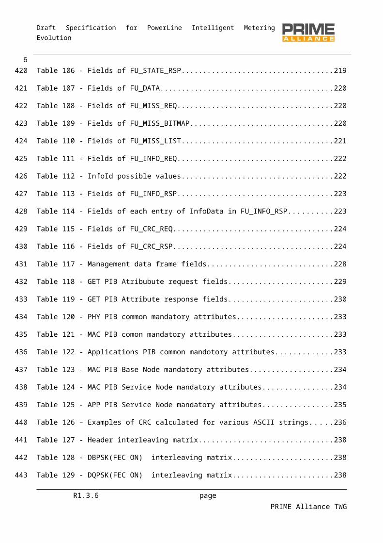
Table 108 - Fields of FU_MISS_REQ..............................................................................................................220
Table 109 - Fields of FU_MISS_BITMAP........................................................................................................220
Table 110 - Fields of FU_MISS_LIST..............................................................................................................221
Table 111 - Fields of FU_INFO_REQ..............................................................................................................222
Table 112 - InfoId possible values.................................................................................................................222
Table 113 - Fields of FU_INFO_RSP...............................................................................................................223
Table 114 - Fields of each entry of InfoData in FU_INFO_RSP......................................................................223
Table 115 - Fields of FU_CRC_REQ...............................................................................................................224
Table 116 - Fields of FU_CRC_RSP................................................................................................................224
Table 117 - Management data frame fields..................................................................................................228
Table 118 - GET PIB Atribubute request fields..............................................................................................229
Table 119 - GET PIB Attribute response fields..............................................................................................230
Table 120 - PHY PIB common mandatory attributes.....................................................................................233
Table 121 - MAC PIB comon mandatory attributes......................................................................................233
Table 122 - Applications PIB common mandotory attributes.......................................................................233
Table 123 - MAC PIB Base Node mandatory attributes................................................................................234
Table 124 - MAC PIB Service Node mandatory attributes............................................................................234
Table 125 - APP PIB Service Node mandatory attributes..............................................................................235
Table 126 – Examples of CRC calculated for various ASCII strings................................................................236
Table 127 - Header interleaving matrix........................................................................................................238
Table 128 - DBPSK(FEC ON) interleaving matrix..........................................................................................238
Table 129 - DQPSK(FEC ON) interleaving matrix..........................................................................................238
Table 130 - D8PSK(FEC ON) interleaving matrix..........................................................................................239
Table 131 - Table of MAC constants.............................................................................................................240
Table 132 - TYPE value assignments.............................................................................................................241
Table 133 - LCID value assignments..............................................................................................................241
Table 134 - Result values for Convergence layer primitives.........................................................................241
R1.3.6 page PRIME Alliance TWG
5390
391
392
393
394
395
396
397
398
399
400
401
402
403
404
405
406
407
408
409
410
411
412
413
414
415
416
Draft Specification for PowerLine Intelligent Metering Evolution
Table 135 – List of frequencies used............................................................................................................244
R1.3.6 page PRIME Alliance TWG
6417
418
Draft Specification for PowerLine Intelligent Metering Evolution
1 Introduction
This document is the technical specification for the OFDM PRIME technology.
1.1 ScopeThis document specifies a PHY layer, a MAC layer and a Convergence layer for complexity-effective, narrowband (<200 kbps) data transmission over electrical power lines that could be part of a Smart Grid system.
1.2 OverviewThe purpose of this document is to specify a narrowband data transmission system based on OFDM modulations scheme for providing mainly core utility services.
The specification currently describes the following:
A PHY layer capable of achieving rates of uncoded 128 kbps (see chapter 3). A MAC layer for the power line environment (see chapter 4). A Convergence layer for adapting several specific services (se chapter 5). A Management Plane (see chapter 6)
The specification is written from the transmitter perspective to ensure interoperability between devices and allow different implementations.
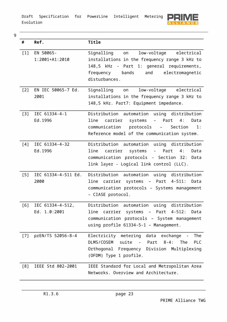
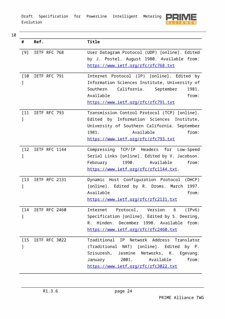
1.3 Normative referencesThe following publications contain provisions which, through reference in this text, constitute provisions of this specification. At the time of publication, the editions indicated were valid. All standards are subject to revision, and parties to agreements based on this Specification are encouraged to investigate the possibility of applying the most recent editions of the following standards:
# Ref. Title
[1] EN 50065-1:2001+A1:2010 Signalling on low-voltage electrical installations in the frequency range 3 kHz to 148,5 kHz - Part 1: general requirements, frequency bands and electromagnetic disturbances.
[2] EN IEC 50065-7 Ed. 2001 Signalling on low-voltage electrical installations in the frequency range 3 kHz to 148,5 kHz. Part7: Equipment impedance.
R1.3.6 page 19 PRIME Alliance TWG
7
419
420
421
422423424
425
426427
428
429430431432
433434
435
436437438439
440
Draft Specification for PowerLine Intelligent Metering Evolution
# Ref. Title
[3] IEC 61334-4-1 Ed.1996 Distribution automation using distribution line carrier systems – Part 4: Data communication protocols – Section 1: Reference model of the communication system.
[4] IEC 61334-4-32 Ed.1996 Distribution automation using distribution line carrier systems - Part 4: Data communication protocols - Section 32: Data link layer - Logical link control (LLC).
[5] IEC 61334-4-511 Ed. 2000 Distribution automation using distribution line carrier systems – Part 4-511: Data communication protocols – Systems management – CIASE protocol.
[6] IEC 61334-4-512, Ed. 1.0:2001
Distribution automation using distribution line carrier systems – Part 4-512: Data communication protocols – System management using profile 61334-5-1 – Management.
[7] prEN/TS 52056-8-4 Electricity metering data exchange - The DLMS/COSEM suite - Part 8-4: The PLC Orthogonal Frequency Division Multiplexing (OFDM) Type 1 profile.
[8] IEEE Std 802-2001 IEEE Standard for Local and Metropolitan Area Networks. Overview and Architecture.
[9] IETF RFC 768 User Datagram Protocol (UDP) [online]. Edited by J. Postel. August 1980. Available from: https://www.ietf.org/rfc/rfc768.txt
[10] IETF RFC 791 Internet Protocol (IP) [online]. Edited by Information Sciences Institute, University of Southern California. September 1981. Available from: https://www.ietf.org/rfc/rfc791.txt
[11] IETF RFC 793 Transmission Control Protocol (TCP) [online]. Edited by Information Sciences Institute, University of Southern California. September 1981. Available from: https://www.ietf.org/rfc/rfc793.txt
[12] IETF RFC 1144 Compressing TCP/IP Headers for Low-Speed Serial Links [online]. Edited by V. Jacobson. February 1990. Available from: https://www.ietf.org/rfc/rfc1144.txt.
[13] IETF RFC 2131 Dynamic Host Configuration Protocol (DHCP) [online]. Edited by R. Droms. March 1997. Available from: https://www.ietf.org/rfc/rfc2131.txt
R1.3.6 page 20 PRIME Alliance TWG
8

Draft Specification for PowerLine Intelligent Metering Evolution
# Ref. Title
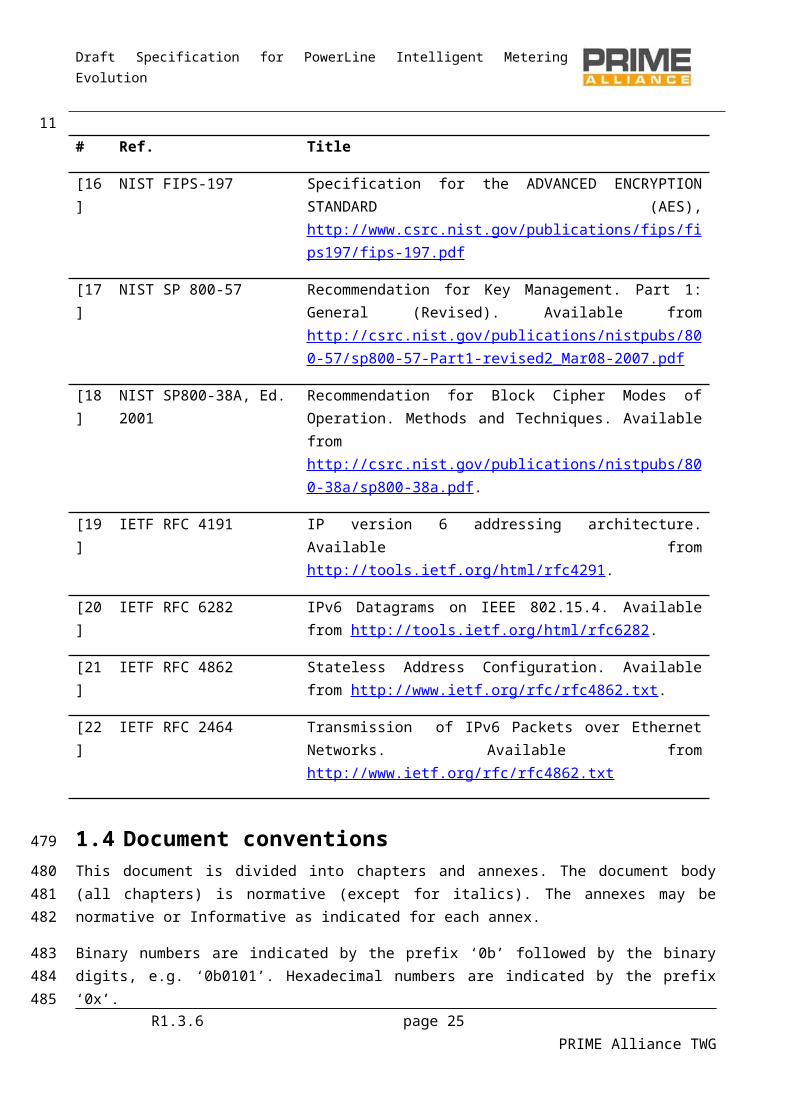
[14] IETF RFC 2460 Internet Protocol, Version 6 (IPv6) Specification [online]. Edited by S. Deering, R. Hinden. December 1998. Available from: https://www.ietf.org/rfc/rfc2460.txt
[15] IETF RFC 3022 Traditional IP Network Address Translator (Traditional NAT) [online]. Edited by P. Srisuresh, Jasmine Networks, K. Egevang. January 2001. Available from: https://www.ietf.org/rfc/rfc3022.txt
[16] NIST FIPS-197 Specification for the ADVANCED ENCRYPTION STANDARD (AES), http://www.csrc.nist.gov/publications/fips/fips197/fips-197.pdf
[17] NIST SP 800-57 Recommendation for Key Management. Part 1: General (Revised). Available from http://csrc.nist.gov/publications/nistpubs/800-57/sp800-57-Part1-revised2_Mar08-2007.pdf
[18] NIST SP800-38A, Ed. 2001 Recommendation for Block Cipher Modes of Operation. Methods and Techniques. Available from http://csrc.nist.gov/publications/nistpubs/800-38a/sp800-38a.pdf.
[19] IETF RFC 4191 IP version 6 addressing architecture. Available from http://tools.ietf.org/html/rfc4291.
[20] IETF RFC 6282 IPv6 Datagrams on IEEE 802.15.4. Available from http://tools.ietf.org/html/rfc6282.
[21] IETF RFC 4862 Stateless Address Configuration. Available from http://www.ietf.org/rfc/rfc4862.txt.
[22] IETF RFC 2464 Transmission of IPv6 Packets over Ethernet Networks. Available from http://www.ietf.org/rfc/rfc4862.txt
1.4 Document conventionsThis document is divided into chapters and annexes. The document body (all chapters) is normative (except for italics). The annexes may be normative or Informative as indicated for each annex.
Binary numbers are indicated by the prefix ‘0b’ followed by the binary digits, e.g. ‘0b0101’. Hexadecimal numbers are indicated by the prefix ‘0x’.
Mandatory requirements are indicated with ‘shall’ in the main body of this document.
Optional requirements are indicated with ‘may’ in the main body of this document. If an option is incorporated in an implementation, it shall be applied as specified in this document.
R1.3.6 page 21 PRIME Alliance TWG
9
441
442443
444445
446
447448
Draft Specification for PowerLine Intelligent Metering Evolution
roof (.) denotes rounding to the closest higher or equal integer.
floor (.) denotes rounding to the closest lower or equal integer.
A mod B denotes the remainder (from 0, 1, …, B-1) obtained when an integer A is divided by an integer B.
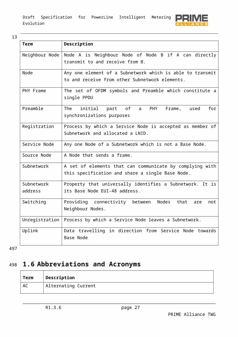
1.5 Definitions
Term Description
Base Node Master Node which controls and manages the resources of a Subnetwork.
Beacon Slot Location of the beacon PDU within a frame.
Destination Node A Node that receives a frame.
Downlink Data travelling in direction from Base Node towards Service Nodes
Level(PHY layer) When used in physical layer (PHY) context, it implies the transmit power level.
Level (MAC layer) When used in medium access control (MAC) context, it implies the position of the reference device in Switching hierarchy.
MAC Frame Composite unit of abstraction of time for channel usage. A MAC Frame is comprised of one or more Beacons, one SCP and zero or one CFP. The transmission of the Beacon by the Base Node acts as delimiter for the MAC Frame.
Neighbour Node Node A is Neighbour Node of Node B if A can directly transmit to and receive from B.
Node Any one element of a Subnetwork which is able to transmit to and receive from other Subnetwork elements.
PHY Frame The set of OFDM symbols and Preamble which constitute a single PPDU
Preamble The initial part of a PHY Frame, used for synchronizations purposes
Registration Process by which a Service Node is accepted as member of Subnetwork and allocated a LNID.
Service Node Any one Node of a Subnetwork which is not a Base Node.
Source Node A Node that sends a frame.
Subnetwork A set of elements that can communicate by complying with this specification and share a single Base Node.
Subnetwork address Property that universally identifies a Subnetwork. It is its Base Node EUI-48 address.
Switching Providing connectivity between Nodes that are not Neighbour Nodes.
R1.3.6 page 22 PRIME Alliance TWG
10449
450
451
452
453
Draft Specification for PowerLine Intelligent Metering Evolution
Term Description
Unregistration Process by which a Service Node leaves a Subnetwork.
Uplink Data travelling in direction from Service Node towards Base Node
1.6 Abbreviations and Acronyms
Term Description
AC Alternating Current
AES Advanced Encryption Standard
AMM Advanced Meter Management
ARQ Automatic Repeat Request
ATM Asynchronous Transfer Mode
BER Bit Error Rate
BPDU Beacon PDU
BPSK Binary Phase Shift Keying
CENELEC European Committee for Electrotechnical Standardization
CFP Contention Free Period
CID Connection Identifier
CL Convergence layer
ClMTUSize
Convergence layer Maximum Transmit Unit Size.
CPCS Common Part Convergence Sublayer
CRC Cyclic Redundancy Check
CSMA-CA Carrier Sense Multiple Access-Collision Avoidance
D8PSK Differential Eight-Phase Shift Keying
DBPSK Differential Binary Phase Shift Keying
DHCP Dynamic Host Configuration Protocol
R1.3.6 page 23 PRIME Alliance TWG
11
454
455
Draft Specification for PowerLine Intelligent Metering Evolution
Term Description
DPSK Differential Phase Shift Keying (general)
DQPSK Differential Quaternary Phase Shift Keying
DSK Device Secret Key
ECB Electronic Code Book
EMA Exponential moving average
ENOB Effective Number Of Bits
EUI-48 48-bit Extended Unique Identifier
EVM Error Vector Magnitude
FCS Frame Check Sequence
FEC Forward Error Correction
FFT Fast Fourier Transform
GK Generation Key
GPDU Generic MAC PDU
HCS Header Check Sum
IEC International Electrotechnical Committee
IEEE Institute of Electrical and Electronics Engineers
IFFT Inverse Fast Fourier Transform
IGMP Internet Group Management Protocol
IPv4 Internet Protocol, Version 4
kbps kilobit per second
KDIV Key Diversifier
LCID Local Connection Identifier
LFSR Linear Feedback Shift Register
LLC Logical Link Control
LNID Local Node Identifier
R1.3.6 page 24 PRIME Alliance TWG
12
Draft Specification for PowerLine Intelligent Metering Evolution
Term Description
LSID Local Switch Identifier
LWK Local Working Key
MAC Medium Access Control
MK Master Key
MLME MAC Layer Management Entity
MPDU MAC Protocol Data Unit
msb Most significant bit
MSDU MAC Service Data Unit
MSPS Million Samples Per Second
MTU Maximum Transmission Unit
NAT Network Address Translation
NID Node Identifier
NSK Network Secret Key
OFDM Orthogonal Frequency Division Multiplexing
PDU Protocol Data Unit
PHY Physical Layer
PIB PLC Information Base
PLC Powerline Communications
PLME PHY Layer Management Entity
PNPDU Promotion Needed PDU
PPDU PHY Protocol Data Unit
ppm Parts per million
PSD Power Spectral Density
PSDU PHY Service Data Unit
QoS Quality of Service
R1.3.6 page 25 PRIME Alliance TWG
13

Draft Specification for PowerLine Intelligent Metering Evolution
Term Description
SAP Service Access Point
SAR Segmentation and Reassembly
SCP Shared Contention Period
SCRC Secure CRC
SDU Service Data Unit
SEC Security
SID Switch Identifier
SNA Subnetwork Address
SNK Subnetwork Key (corresponds to either REG.SNK or SEC.SNK)
SNR Signal to Noise Ratio
SP Security Profile
SSCS Service Specific Convergence Sublayer
SWK Subnetwork Working Key
TCP Transmission Control Protocol
TOS Type Of Service
UI Unique Identifier
USK Unique Secret Key
VJ Van Jacobson
WK Working Key
R1.3.6 page 26 PRIME Alliance TWG
14
Draft Specification for PowerLine Intelligent Metering Evolution
2 General Description
2.1 IntroductionThis document is the Specification for a solution for PLC in the CENELEC A-Band using OFDM modulation scheme.
2.2 General description of the architectureFigure 1 below depicts the communication layers and the scope of this specification. This specification focuses mainly on the data, control and management plane.
Physical (PHY) Layer
Media Access Control (MAC) Layer
Convergence (CL) Layer
Control and Data Plane Management Plane
MLME-SAP MAC Layer Mgmt. Entity (MLME)
PHY Layer Mgmt. Entity (PLME)PLME-SAP
Figure 1 - Reference model of protocol layers used in the OFDM PRIME specification
The CL classifies traffic associating it with its proper MAC connection; this layer performs the mapping of any kind of traffic to be properly included in MSDUs. It may also include header compression functions. Several SSCSs are defined to accommodate different kinds of traffic into MSDUs.
The MAC layer provides core MAC functionalities of system access, bandwidth allocation, connection establishment/maintenance and topology resolution.
The PHY layer transmits and receives MPDUs between Neighbor Nodes using orthogonal frequency division multiplexing (OFDM). OFDM is chosen as the modulation technique because of:
its inherent adaptability in the presence of frequency selective channels (which are common but unpredictable, due to narrowband interference or unintentional jamming);
its robustness to impulsive noise, resulting from the extended symbol duration and use of FEC; its capacity for achieving high spectral efficiencies with simple transceiver implementations.
The PHY specification, described in Chapter 3, also employs a flexible coding scheme. The PHY data rates can be adapted to channel and noise conditions by the MAC.
R1.3.6 page 27 PRIME Alliance TWG
15
456
457
458459
460
461462
463
464
465466467
468469
470471
472473474475
476477

Draft Specification for PowerLine Intelligent Metering Evolution
3 Physical layer
3.1 IntroductionThis chapter specifies the Physical Layer (PHY) Entity for an OFDM modulation scheme in the CENELEC A-band. The PHY entity uses frequencies in the band 3 kHz up to 95 kHz as defined in EN 50065-1:2001+A1:2010 Section 4.1. The use of frequencies in this band is reserved to electricity distributors and their licensees. It is well known that frequencies below 40 kHz show several problems in typical LV power lines. For example:
load impedance magnitude seen by transmitters is sometimes below 1Ω, especially for Base Nodes located at transformers;
colored background noise, which is always present in power lines and caused by the summation of numerous noise sources with relatively low power, exponentially increases its amplitude towards lower frequencies;
meter rooms pose an additional problem, as consumer behaviors are known to have a deeper impact on channel properties at low frequencies, i.e. operation of all kind of household appliances leads to significant and unpredictable time-variance of both the transfer function characteristics and the noise scenario.
Consequently, the OFDM PRIME PHY specification uses the frequency band from 41.992 kHz to 88.867 kHz. This is achieved by using OFDM modulation with signal loaded on 97 (96 data and one pilot) equally spaced subcarriers, transmitted in symbols of 2240 microseconds, of which 192 microseconds are comprised of a short cyclic prefix.
Differential modulation is used, with one of three possible constellations: DBPSK, DQPSK or D8PSK. Thus, theoretical uncoded speeds of approximately 47 kbps, 94 kbps and 141 kbps (without accounting for cyclic prefix overhead) can be obtained.
An additive scrambler is used to avoid the occurrence of long sequences of identical bits.
Finally, ½ rate convolutional coding will be used along with bit interleaving. This can be disabled by higher layers if the channel is good enough and higher throughputs are needed.
3.2 OverviewOn the transmitter side, the PHY Layer receives a MPDU from the MAC layer and generates a PHY Frame.
The processing of the header and the PPDU is shown in Figure 2, and consists of the following steps.
A CRC is appended to the PHY header (CRC for the payload is appended by the MAC layer, so no additional CRC is inserted by the PHY). Next, convolutional encoding is performed, if the optional FEC is enabled. (Note that the PHY header is always encoded). The next step is scrambling, which is done for both PHY header and the PPDU, irrespective of whether FEC is enabled. If FEC is enabled, the scrambler output is also interleaved.
R1.3.6 page 28 PRIME Alliance TWG
16
478
479
480481482483484
485486487488489490491492493
494495496497
498499500
501
502503
504
505
506
507508509510511

Draft Specification for PowerLine Intelligent Metering Evolution
The scrambled (and interleaved) bits are differentially modulated using a DBPSK, DQPSK or D8PSK scheme. The next step is OFDM, which comprises the IFFT (Inverse Fast Fourier Transform) block and the cyclic prefix generator. When header and data bits are input to the chain shown in Figure 2, the output of the cyclic prefix generation is a concatenation of OFDM symbols constituting the header and payload portions of the PPDU respectively. The header portion contains two OFDM symbols, while the payload portion contains M OFDM symbols. The value of M is signalled in the PHY header, as described in Section 3.4.3
CRC Convolutional encoder Scrambler Interleaver Sub-carrier
modulator IFFT Cyclic prefix
Figure 2 - Overview of PPDU processing
The structure of the PHY Frame is shown in Figure 3. Each PHY Frame starts with a preamble lasting 2.048 ms, followed by a number of OFDM symbols, each lasting 2.24 ms. The first two OFDM symbols carry the PHY Frame header, also referred to as the header in this specification. The header is also generated from using a process similar to the payload generation, as described in Section 3.4.3. The remaining M OFDM symbols carry payload, generated as described in Section 3.4.3. The value of M is signaled in the header, and is at most equal to 63.
PREAMBLE HEADER PAYLOAD
2.048ms 4.48ms Mx2.24ms
2 symbols M symbols
Figure 3 - PHY Frame Format
3.3 PHY parametersTable 1 lists the frequency and timing parameters used in the OFDM PRIME PHY. These parameters are common for all constellation/coding combinations.
Note Note that throughout this document, a sampling rate of 250 kHz and 512-point FFT sizes are defined for specification convenience of the OFDM signals and are not intended to indicate a requirement on the implementation
Table 1 - Frequency and Timing Parameters Of the OFDM PRIME PHY
Parameter Values
Base Band clock (Hz) 250000
Subcarrier spacing (Hz) 488.28125
Number of data subcarriers 84 (header) 96 (payload)
R1.3.6 page 29 PRIME Alliance TWG
17512513514515516517
518
519
520
521522523524525526
527528
529
530531
532533534
535
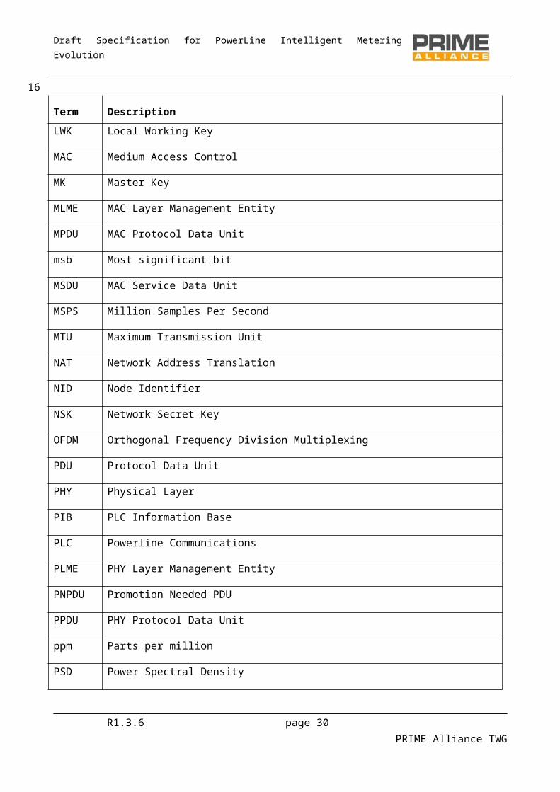
Draft Specification for PowerLine Intelligent Metering Evolution
Parameter Values
Number of pilot subcarriers 13 (header) 1 (payload)
FFT interval (samples 512
FFT interval (µs) 2048
Cyclic Prefix (samples) 48
Cyclic Prefix (µs) 192
Symbol interval (samples) 560
Symbol interval (µs) 2240
Preamble period (µs) 2048
Table 2 below shows the PHY data rate during payload transmission, and maximum MSDU length for various modulation and coding combinations.
Table 2 - PHY data rate and packet size parameters, for various modulation and coding schemes
DBPSK DQPSK D8PSKConvolutional Code (1/2) On Off On Off On OffInformation bits per subcarrier NBPSC 0.5 1 1 2 1.5 3Information bits per OFDM symbol NBPS 48 96 96 192 144 288Raw data rate (kbps approx) 21.4 42.9 42.9 85.7 64.3 128.6Maximum MSDU length with 63 symbols (in bits) 3016 6048 6040 12096 9064 18144Maximum MSDU length with 63 symbols (in bytes)” 377 756 755 1512 1133 2268
Table 3 shows the modulation and coding scheme and the size of the header portion of the PHY Frame (see Section 3.4.3).
Table 3 - Header Parameters
DBPSKConvolutional Code (1/2) OnInformation bits per subcarrier NBPSC 0.5Information bits per OFDM symbol NBPS 42
It is strongly recommended that all frequencies used to generate the OFDM transmit signal come from one single frequency reference. The system clock shall have a maximum tolerance of ±50 ppm, including ageing.
R1.3.6 page 30 PRIME Alliance TWG
18
536
537538
539
540
541542
543
544
545546

Draft Specification for PowerLine Intelligent Metering Evolution
3.4 Preamble, header and payload structure
3.4.1 PreambleThe preamble is used at the beginning of every PPDU for synchronization purposes. In order to provide a maximum of energy, a constant envelope signal is used instead of OFDM symbols. There is also a need for the preamble to have frequency agility that will allow synchronization in the presence of frequency selective attenuation and, of course, excellent aperiodic autocorrelation properties are mandatory. A linear chirp signal meets all the above requirements. The waveform of the preamble is defined as:
SCH ( t ) =A⋅rect ( t /T )⋅cos [2π ( f 0 t+1/2μt 2) ]
where T= 2048µs, f0= 41992 Hz (start frequency), μ= (ff – f0 ) / T, with the final frequency ff = 88867 Hz. The choice of the parameter A determines the average preamble power (given by A2 / 2), and is further discussed in Section 3.8
The rect function is defined as:
rect (t )=1 , 0<t< 1rect (t )=0 , otherwise
3.4.2 Pilot structureThe preamble is followed by two OFDM symbols comprising the header. Both these OFDM symbols contain 13 pilot subcarriers, which could be used to estimate the sampling start error and the sampling frequency offset.
For subsequent OFDM symbols, one pilot subcarrier is used to provide a phase reference for frequency domain DPSK demodulation.
Pilot subcarrier frequency allocation is shown in Figure 4 and Figure 5, where Pi is the ith pilot subcarrier and Di is the ith data subcarrier.
R1.3.6 page 31 PRIME Alliance TWG
19
547
548
549550551552553
554
555
556557558
559
560
561
562563564
565566
567568
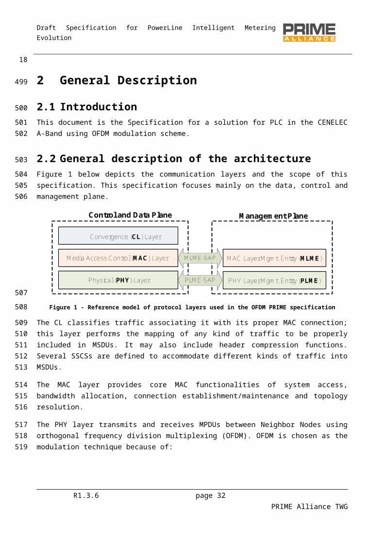
Draft Specification for PowerLine Intelligent Metering Evolution
Figure 4 - Pilot and data subcarrier allocation (OFDM symbols vs subcarriers)
Sub-carrier number (FFT 512)
86 87 93 94 95 101 102 103 109 110 111 117 118 119 125 126 127 133 134 135 141 142 143 149 150 151 157 158 159 165 166 167 173 174 175 181 182
… … … … … … … … … … … …
P1 D1 D7 P2 D8 D14 P3 D15 D21 P4 D22 D28 P5 D29 D35 P6 D36 D42 P7 D43 D49 P8 D50 D56 P9 D57 D63 P10 D64 D70 P11 D71 D77 P12 D78 D84 P13
Sub-carrier number (FFT 512)
86 87 93 94 95 101 102 103 109 110 111 117 118 119 125 126 127 133 134 135 141 142 143 149 150 151 157 158 159 165 166 167 173 174 175 181 182
… … … … … … … … … … … …
P1 D1 D7 P2 D8 D14 P3 D15 D21 P4 D22 D28 P5 D29 D35 P6 D36 D42 P7 D43 D49 P8 D50 D56 P9 D57 D63 P10 D64 D70 P11 D71 D77 P12 D78 D84 P13 Subcarrier (512-point FFT)
Figure 5 - Pilot and data subcarrier frequency allocation inside the header
Pilot subcarriers are BPSK modulated by a pseudo-random binary sequence (the pseudo-randomness avoids generation of spectral lines). The phase of the pilot subcarriers is controlled by the sequence pn, which is a cyclic extension of the 127-bit sequence given by:
Pref0.126 = 0,0,0,0,1,1,1,0,1,1,1,1,0,0,1,0,1,1,0,0,1,0,0,1,0,0,0,0,0,0,1,0,0,0,1,0,0,1,1,0,0,0,1,0,1,1,1,0,1,0,1,1, 0,1,1,0,0,0,0,0,1,1,0,0,1,1,0,1,0,1,0,0,1,1,1,0,0,1,1,1,1,0,1,1,0,1,0,0,0,0,1,0,1,0,1,0,1,1,1,1,1,0,1,0,0,1,0,1,0,0,0,1,1,0,1,1,1,0,0,0,1,1,1,1,1,1,1
In the above, ‘1’ means 180º phase shift and ‘0’ means 0º phase shift. One bit of the sequence will be used for each pilot subcarrier, starting with the first pilot subcarrier in the first OFDM symbol, then the next pilot subcarrier, and so on. The same process is used for the second OFDM symbol. For subsequent OFDM symbols, one element of the sequence is used for the pilot subcarrier (see Figure 5).
The sequence pn is generated by the scrambler defined in Figure 6 when the “all ones” initial state is used.
R1.3.6 page 32 PRIME Alliance TWG
20
569570
571
572573
574575576
577578579
580581582583
584

Draft Specification for PowerLine Intelligent Metering Evolution
1 1 1 1 1 1 Outputsequence11 1 1 1 1 1 Outputsequence1
Figure 6 - LFSR for use in Pilot sequence generation
Loading of the sequence pn shall be initiated at the start of every PPDU, just after the Preamble.
3.4.3 Header and PayloadThe header is composed of two OFDM symbols, which are always sent using DBPSK modulation and FEC (convolutional coding) ‘On’. However the payload is DBPSK, DQPSK or D8PSK modulated, depending on the configuration by the MAC layer. The MAC layer may select the best modulation scheme using information from errors in previous transmissions to the same receiver(s), or by using the SNR feedback. Thus, the system will then configure itself dynamically to provide the best compromise between throughput and efficiency in the communication. This includes deciding whether or not FEC (convolutional coding) is used.
Note: The optimization metric and the target error rate for the selection of modulation and FEC scheme is left to individual implementations
The first two OFDM symbols in the PPDU (corresponding to the header) are composed of 84 data subcarriers and 13 pilot subcarriers. After the header, each OFDM symbol in the payload carries 96 data subcarriers and one pilot subcarrier. Each data subcarrier carries 1, 2 or 3 bits.The bit stream from each field must be sent msb first.
PROTOCOL
4
LEN
6
PAD_LEN
6
MAC_H
54
CRC_Ctrl
8
FLUSHING_H
6
MSDU
8xM
FLUSHING_P
8
PAD
8
PAYLOADHEADER
bits
Figure 7 - PPDU: header and payload (bits transmitted before encoding)
HEADER: Each PPDU contains both PHY and MAC header information. To avoid ambiguity, the MAC header is always referred to as such. The PHY header may also be referred to as just “header’. It is composed of the following fields:o PROTOCOL: contains the transmission scheme of the payload. Added by the PHY layer.o
0 1 2 3 4 5 6 7 8 9 10 11 12 13 14 15DBPSK DQPSK D8PSK RES DBPSK_F DQPSK_F D8PSK_F RES RES RES RES RES RES RES RES RES
o Where RES means “Reserved” and the suffix “_F” means FEC is ‘On’.o LEN: defines the length of the payload (after coding) in OFDM symbols. Added by the PHY layer.o PAD_LEN: defines the length of the PAD field (before coding) in bytes. Added by the PHY layer.o MAC_H: MAC layer Header. It is included inside the header symbols to protect the information
contained. Note that the MAC header is generated by the MAC layer, and only the first 54 bits of the MAC header are embedded in the PHY header.
R1.3.6 page 33 PRIME Alliance TWG
21
585586
587
588
589590591592593594595596597598599600601602
603604
605
606607608609610
611611612613614615616

Draft Specification for PowerLine Intelligent Metering Evolution
o CRC_Ctrl: the CRC_Ctrl(m), m = 0..7, contains the CRC checksum over PROTOCOL, LEN, PAD_LEN and MAC_H field (PD_Ctrl). The polynomial form of PD_Ctrl is expressed as follows:
∑m=0
69
PDCtrl(m) xm
o The checksum is calculated as follows: the remainder of the division of PD_Ctrl by the
polynomial x8 +x2 +x+1 forms CRC_Ctrl(m), where CRC_Ctrl(0) is the LSB. The generator
polynomial is the well-known CRC-8-ATM. Some examples are shown in Annex A. Added by the PHY layer.
o FLUSHING_H: flushing bits needed for convolutional decoding. All bits in this field are set to zero to reset the convolutional encoder. Added by the PHY layer.
PAYLOAD:
o MSDU: Uncoded MAC layer Service Data Unit.o FLUSHING_P: flushing bits needed for convolutional decoding. All bits in this field are set to zero
to reset the convolutional encoder. This field only exists when FEC is ‘On’.o PAD: Padding field. In order to ensure that the number of (coded) bits generated in the payload
fills an integer number of OFDM symbols, pad bits may be added to the payload before encoding. All pad bits shall be set to zero.
3.5 Convolutional encoderThe uncoded bit stream may go through convolutional coding to form the coded bit stream. The convolutional encoder is ½ rate with constraint length K = 7 and code generator polynomials 1111001 and 1011011. At the start of every PPDU transmission, the encoder state is set to zero. As seen in Figure 8, eight zeros are inserted at the end of the header information bits to flush the encoder and return the state to zero. Similarly, if convolutional encoding is used for the payload, six zeros bits are again inserted at the end of the input bit stream to ensure the encoder state returns to zero at the end of the payload. The block diagram of the encoder is shown in Figure 9
+
Z -1 Z -1 Z -1 Z -1 Z -1 Z -1
+
0 0
00
1
1
1 1
1 1
1
1
1
1
Input
First output
Second output
Figure 8 - Convolutional encoder
R1.3.6 page 34 PRIME Alliance TWG
22617618
619620
621622623624625626627
628629630631632633
634
635636637638639640641
642
643

Draft Specification for PowerLine Intelligent Metering Evolution
3.6 ScramblerThe scrambler block randomizes the bit stream, so it reduces the crest factor at the output of the IFFT when a long stream of zeros or ones occurs in the header or payload bits after coding (if any). Scrambling is always performed regardless of the modulation and coding configuration.
The scrambler block performs a xor of the input bit stream by a pseudo noise sequence pn, obtained by cyclic extension of the 127-element sequence given by:
Pref0..126= 0,0,0,0,1,1,1,0,1,1,1,1,0,0,1,0,1,1,0,0,1,0,0,1,0,0,0,0,0,0,1,0,0,0,1,0,0,1,1,0,0,0,1,0,1,1,1,0,1,0,1,1,0,1,1,0,0,0,0,0,1,1,0,0,1,1,0,1,0,1,0,0,1,1,1,0,0,1,1,1,1,0,1,1,0,1,0,0,0,0,1,0,1,0,1,0,1,1,1,1,1,0,1,0,0,1,0,1,0,0,0,1,1,0,1,1,1,0,0,0,1,1,1,1,1,1,1
Note: The above 127-bit sequence can be generated by the LFSR defined in Figure 9 when the “all ones” initial state is used.
1 1 1 1 1 1 Outputsequence1
Inputsequence
1 1 1 1 1 1 Outputsequence1
Inputsequence
Figure 9 - LFSR for use in the scrambler block
Loading of the sequence pn shall be initiated at the start of every PPDU, just after the Preamble.
3.7 InterleaverBecause of the frequency fading (narrowband interference) of typical powerline channels, OFDM subcarriers are generally received at different amplitudes. Deep fades in the spectrum may cause groups of subcarriers to be less reliable than others, thereby causing bit errors to occur in bursts rather than be randomly scattered. If (and only if) coding is used as described in 3.4, interleaving is applied to randomize the occurrence of bit errors prior to decoding. At the transmitter, the coded bits are permuted in a certain way, which makes sure that adjacent bits are separated by several bits after interleaving.
Let NCBPS = 2×NBPS be the number of coded bits per OFDM symbol in the cases convolutional coding is used. All coded bits must be interleaved by a block interleaver with a block size corresponding to N CBPS. The interleaver ensures that adjacent coded bits are mapped onto non-adjacent data subcarriers. Let v(k), with k = 0,1,…, NCBPS –1, be the coded bits vector at the interleaver input. v(k) is transformed into an interleaved vector w(i), with i = 0,1,…, NCBPS –1, by the block interleaver as follows:
w( (NCBPS /s) × (k mod s) + floor(k/s) ) = v(k) k = 0,1,…, NCBPS –1The value of s is determined by the number of coded bits per subcarrier, N CBPSC = 2×NBPSC. NCBPSC is related to NCBPS such that NCBPS =96×NCBPSC (payload) and NCBPS =84×NCBPSC (header)
s = 8 × (1+ floor(NCBPSC/2)) for the payload and s = 7 for the header.
R1.3.6 page 35 PRIME Alliance TWG
23
644
645646647
648649
650651652653
654655
656657
658
659
660661662663664665
666667668669670
671672673
674675
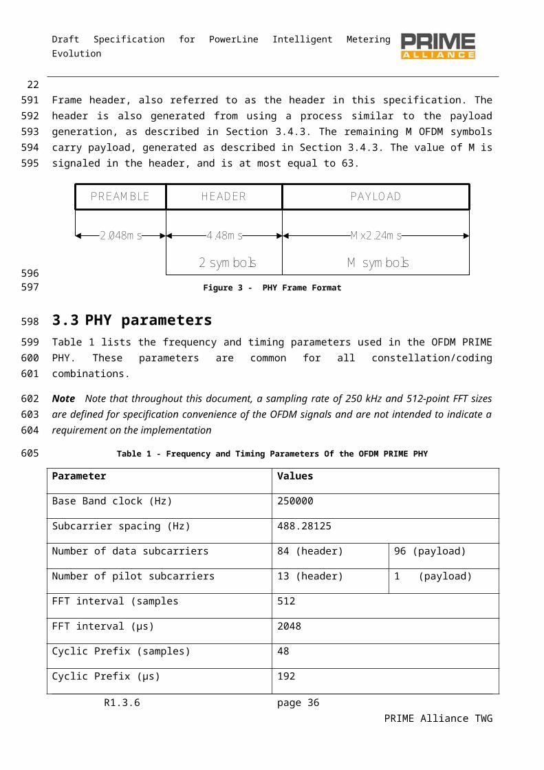
Draft Specification for PowerLine Intelligent Metering Evolution
At the receiver, the de-interleaver performs the inverse operation. Hence, if w ’(i), with i = 0,1,…, NCBPS –1, is the de-interleaver vector input, the vector w ’(i) is transformed into a de-interleaved vector v’(k), with k = 0,1,…, NCBPS –1, by the block de-interleaver as follows:
v’ ( s × i – (NCBPS–1) × floor(s × i/NCBPS) ) = w’(i) i = 0,1,…, NCBPS –1Descriptive tables showing index permutations can be found in Annex C for reference.
3.8 ModulationThe PPDU payload is modulated as a multicarrier differential phase shift keying signal with one pilot subcarrier and 96 data subcarriers that comprise 96, 192 or 288 bits per symbol. The header is modulated DBPSK with 13 pilot subcarriers and 84 data subcarriers that comprise 84 bits per symbol.
The bit stream coming from the interleaver is divided into groups of M bits where the first bit of the group of M is the most significant bit (msb).
First of all, frequency domain differential modulation is performed. Figure 10 shows the DBPSK, DQPSK and D8PSK mapping:
1 0
Q
DBPSK
010
111
001
100
Q
Msb Lsb
D8PSK
101
000110
011
I I
Q
Msb Lsb
DQPSK
10
0011
01
I1 0
Q
DBPSK
010
111
001
100
Q
Msb Lsb
D8PSK
101
000110
011
I I
Q
Msb Lsb
DQPSK
10
0011
01
I
Figure 10 - DBPSK, DQPSK and D8PSK mapping
The next equation defines the M-ary DPSK constellation of M phases:
sk =Ae jθk
Where: k is the frequency index representing the k-th subcarrier in an OFDM symbol. k = 1 corresponds to
the phase reference pilot subcarrier. sk is the modulator output (a complex number) for the kth given subcarrier.
θk stands for the absolute phase of the modulated signal, and is obtained as follows:
θk=(θk−1+(2π / M ) Δbk ) mod 2π
This equation applies for k > 1 in the payload, the k = 1 subcarrier being the phase reference pilot. When the header is transmitted, the pilot allocated in the k -th subcarrier is used as a phase reference for the data allocated in the k 1-th subcarrier.
R1.3.6 page 36 PRIME Alliance TWG
24676677678
679680
681
682683684
685686
687688
689
690
691
692693694695696
697
698
699700701
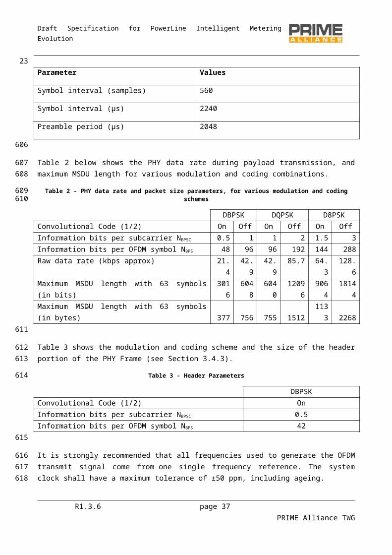
Draft Specification for PowerLine Intelligent Metering Evolution
Δbk∈ 0,1 ,. .. ,M−1 represents the information coded in the phase increment, as supplied by the constellation encoder.
M = 2, 4, or 8 in the case of DBPSK, DQPSK or D8PSK, respectively. A is a shaping parameter and represents the ring radius from the centre of the constellation. The
value of A determines the power in each subcarrier and hence the average power transmitted in the header and payload symbols.
The OFDM symbol can be expressed in mathematical form:
c i(n )=∑k= 86
182
s( k−85 ,i )exp ( j2π512
k (n−NCP))+ ∑k=330
426
s∗( 427−k,i)exp( j2π512
k ( n−NCP)) i is the time index representing the i-th OFDM symbol; i = 0, 1, …, M+1. s(k,i) is the complex value from the subcarrier modulation block, and the symbol * denotes complex
conjugate. n is the sample index; 0 n 559.
Note 1: Note that ci(n+512) = ci(n), so the first 48 samples of the above are equal to the last 48 samples, and therefore constitute the cyclic prefix. Some samples of the cyclic prefix may be used for vendor-specific windowing. Note 2: While the exact details of windowing are left to individual implementations, note that PRIME-certified devices must obey the EVM limit specified by certification tests, with the EVM measurement procedure mentioned in Annex B
If a complex 512-point IFFT is used, the 96 subcarriers shall be mapped as shown in Figure 11. The symbol * represents complex conjugate.
Figure 11 - Subcarrier Mapping
After the IFFT, the symbol is cyclically extended by 48 samples to create the cyclic prefix (NCP).
R1.3.6 page 37 PRIME Alliance TWG
25
702703704705706707
708
709
710711712713
714715716717718719720721722723
724
725
726

Draft Specification for PowerLine Intelligent Metering Evolution
3.9 Electrical specification of the transmitter
3.9.1 GeneralThe following requirements establish the minimum technical transmitter requirements for interoperability, and adequate transmitter performance.
3.9.2 Transmit PSDTransmitter specifications will be measured according to the following conditions and set-up.
For single-phase devices, the measurement shall be taken on either the phase or neutral connection according to Figure 12.
P/N: Mains Phase/NeutralD: Device under testM: MeasurementG: Ground
Figure 12 – Measurement set up (single-phase)
For three-phase devices which transmit on all three phases simultaneously, measurements shall be taken in all three phases as per Figure 13. No measurement is required on the neutral conductor.
P/N: Mains Phase/NeutralD: Device under testM: MeasurementG: Ground
R1.3.6 page 38 PRIME Alliance TWG
26
727
728
729730
731
732
733734
735
736
737738
739
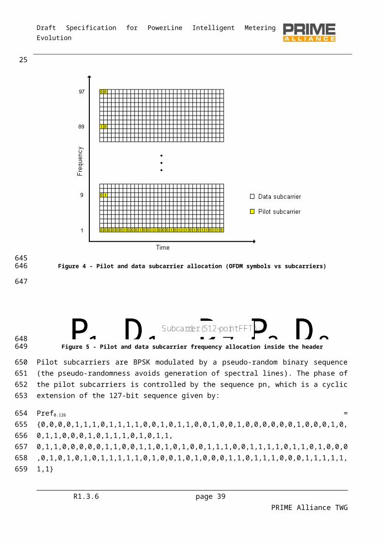
Draft Specification for PowerLine Intelligent Metering Evolution
Figure 13 – Measurement set up (three-phase)
The artificial mains network in Figure 12 and Figure 13 is shown in Figure 14. It is based on EN 50065-1:2001. The 33uF capacitor and 1Ω resistor have been introduced so that the network has an impedance of 2Ω in the frequency band of interest.
P/N: Mains Phase/NeutralD: Device under testM: MeasurementG: Ground
Figure 14 – Artificial mains network
All transmitter output voltages are specified as the voltage measured at the line Terminal with respect to the neutral Terminal. Accordingly, values obtained from the measuring device must be increased by 6 dB (voltage divider of ratio ½).
All devices will be tested to comply with PSD requirements over the full temperature range, which depends on the type of Node:
Base Nodes in the range -40°C to +70°C Service Nodes in the range -25°C to +55°C
All tests shall be carried out under normal traffic load conditions.
In all cases, the PSD must be compliant with the regulations in force in the country where the system is used.
When driving only one phase, the power amplifier shall be capable of injecting a final signal level in the transmission Node (S1 parameter) of 120dBµVrms (1 Vrms). This could be in one of two scenarios: either the DUT is connected to a single phase as shown in Figure 12; or the DUT is connected to three phases as shown in Figure 13, but drives only one phase at a time. In both cases, connection is through the AMN of Figure 14.
For three-phase devices injecting simultaneously into all three phases, the final signal level shall be 114dBµVrms (0.5Vrms).
Note 1: In all the above cases, note the measurement equipment has some insertion loss. Specifically, in the single-phase, configuration, the measured voltage is 6 dB below the injected signal level, and will equal 114 dBuV when the injected signal level is 120 dBuV. Similarly, when connected to three phases, the measured signal level will be 12 dB below the injected signal level. Thus, a 114 dBuV signal injected into three phases being driven simultaneously, will be measured as 102 dBuV on any of the three meters of Figure 13.
Note 2: Regional restrictions may apply, ex., on the reactive power drawn from a meter including a OFDM PRIME modem. These regulations could affect the powerline interface, and should be accounted for.
R1.3.6 page 39 PRIME Alliance TWG
27740
741742743
744
745
746747748
749750
751752
753
754755
756757758759760
761762
763764765766767
768769
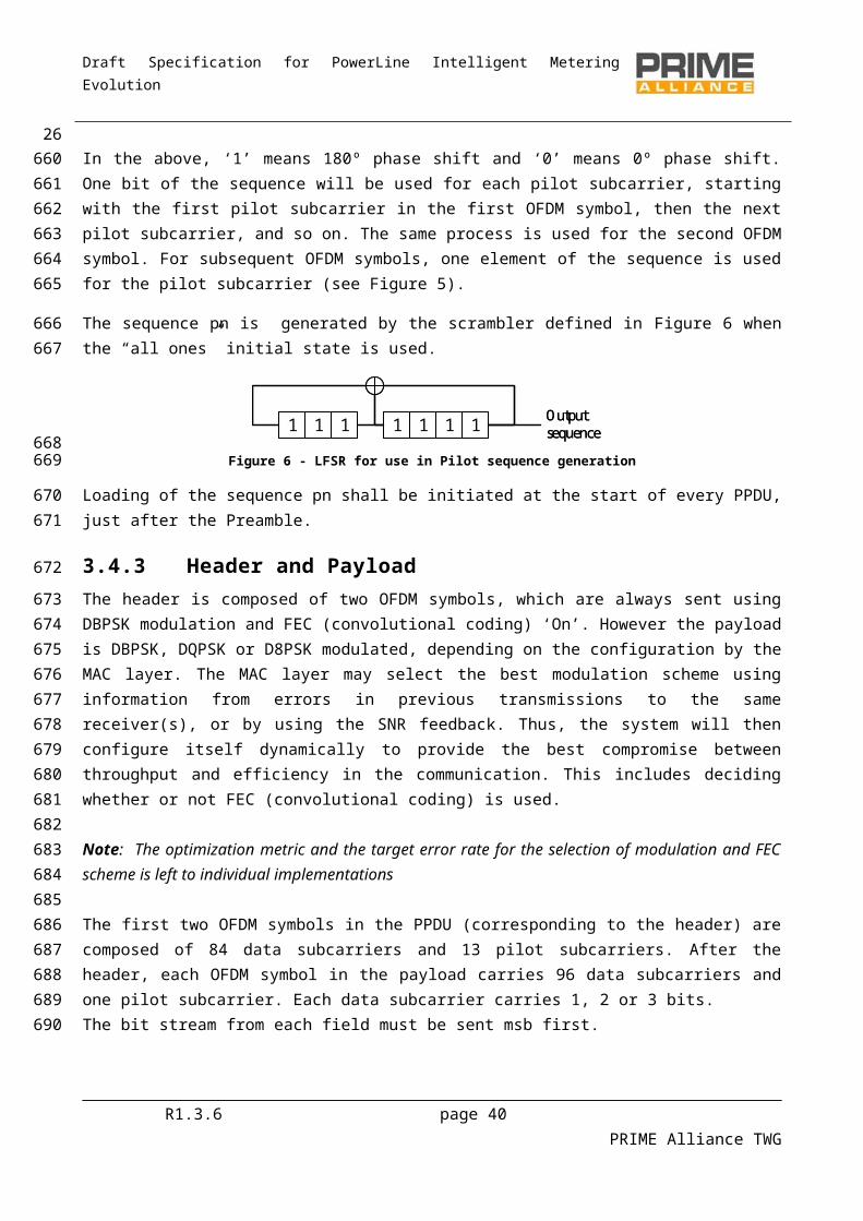
Draft Specification for PowerLine Intelligent Metering Evolution
3.9.3 Error Vector Magnitude (EVM)The quality of the injected signal with regard to the artificial mains network impedance must be measured in order to validate the transmitter device. Accordingly, a vector analyzer that provides EVM measurements (EVM meter) shall be used, see Annex B for EVM definition. The test set-up described in Figure 12 and Figure 13 shall be used in the case of single-phase devices and three-phase devices transmitting simultaneously on all phases, respectively.
BPFADC EVM
PROCESING
M
G
BPFBPFADC EVM
PROCESING
M
G
Figure 15 – EVM meter (block diagram)
The EVM meter must include a Band Pass Filter with an attenuation of 40 dB at 50 Hz that ensures anti-aliasing for the ADC. The minimum performance of the ADC is 1MSPS, 14-bit ENOB. The ripple and the group delay of the band pass filter must be accounted for in EVM calculations.
3.9.4 Conducted disturbance limitsRegional regulations may apply. For instance, in Europe, transmitters shall comply with the maximum emission levels and spurious emissions defined in EN50065-1:2001 for conducted emissions in AC mains in the bands 3 kHz to 9 kHz and 95 kHz to 30 MHz. European regulations also require that transmitters and receivers shall comply with impedance limits defined in EN50065-7:2001 in the range 3 kHz to 148.5 kHz.
3.10 PHY service specification
3.10.1 GeneralPHY shall have a single 20-bit free-running clock incremented in steps of 10 μs. The clock counts from 0 to 1048575 then overflows back to 0. As a result the period of this clock is 10.48576 seconds. The clock is never stopped nor restarted. Time measured by this clock is the one to be used in some PHY primitives to indicate a specific instant in time.
R1.3.6 page 40 PRIME Alliance TWG
28
770
771772773774775
776
777
778779780
781
782783784785
786
787
788789790791
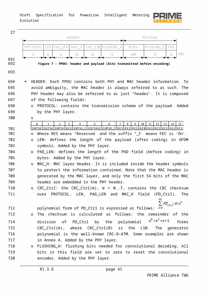
Draft Specification for PowerLine Intelligent Metering Evolution
3.10.2 PHY Data plane primitives
3.10.2.1 General
MA
C
PHY
PHY_DATA.indication
PHY_DATA.request
PHY_DATA.confirm
Figure 16 – Overview of PHY primitives
The request primitive is passed from MAC to PHY to request the initiation of a service.
The indication and confirm primitives are passed from PHY to MAC to indicate an internal PHY event that is significant to MAC. This event may be logically related to a remote service request or may be caused by an event internal to PHY.
3.10.2.2 PHY_DATA.request
3.10.2.2.1 Function
The PHY_DATA.request primitive is passed to the PHY layer entity to request the sending of a PPDU to one or more remote PHY entities using the PHY transmission procedures. It also allows setting the time at which the transmission must be started.
3.10.2.2.2 Structure
The semantics of this primitive are as follows:
PHY_DATA.requestMPDU, Length, Level, Scheme, Time.
The MPDU parameter specifies the MAC protocol data unit to be transmitted by the PHY layer entity. It is mandatory for implementations to byte-align the MPDU across the PHY-SAP. This implies 2 extra bits (due to the non-byte-aligned nature of the MAC layer Header) to be located at the beginning of the header.
The Length parameter specifies the length of MPDU in bytes. Length is 2 bytes long.
The Level parameter specifies the output signal level according to which the PHY layer transmits MPDU. It may take one of eight values:
0: Maximal output level (MOL)
1: MOL -3 dB
2: MOL -6 dB
R1.3.6 page 41 PRIME Alliance TWG
29
792
793
794
795
796
797798799
800
801
802803804
805
806
807
808809810
811
812813
814
815
816

Draft Specification for PowerLine Intelligent Metering Evolution
…
7: MOL -21 dB
The Scheme parameter specifies the transmission scheme to be used for MPDU. It can have any of the following values:
0: DBPSK
1: DQPSK
2: D8PSK
3: Not used
4: DBPSK + Convolutional Code
5: DQPSK + Convolutional Code
6: D8PSK + Convolutional Code
7: Not used
The Time parameter specifies the instant in time in which the MPDU has to be transmitted. It is expressed in 10s of µs and may take values from 0 to 220-1.
Note that the Time parameter should be calculated by the MAC, taking into account the current PHY time which may be obtained by PHY_timer.get primitive. The MAC should account for the fact that no part of the PPDU can be transmitted during beacon slots and CFP periods granted to other devices in the network. If the time parameter is set such that these rules are violated, the PHY will return a fail in PHY_Data.confirm.
3.10.2.2.3 Use
The primitive is generated by the MAC layer entity whenever data is to be transmitted to a peer MAC entity or entities.
The reception of this primitive will cause the PHY entity to perform all the PHY-specific actions and pass the properly formed PPDU to the powerline coupling unit for transfer to the peer PHY layer entity or entities. The next transmission shall start when Time = Timer.
3.10.2.3 PHY_DATA.confirm
3.10.2.3.1 Function
The PHY_DATA.confirm primitive has only local significance and provides an appropriate response to a PHY_DATA.request primitive. The PHY_DATA.confirm primitive tells the MAC layer entity whether or not the MPDU of the previous PHY_DATA.request has been successfully transmitted.
3.10.2.3.2 Structure
The semantics of this primitive are as follows:
R1.3.6 page 42 PRIME Alliance TWG
30817
818
819820
821
822
823
824
825
826
827
828
829830
831832833834
835
836837
838839840
841
842
843844845
846
847

Draft Specification for PowerLine Intelligent Metering Evolution
PHY_DATA.confirmResult.
The Result parameter is used to pass status information back to the local requesting entity. It is used to indicate the success or failure of the previous associated PHY_DATA.request. Some results will be standard for all implementations:
0: Success.
1: Too late. Time for transmission is past.
2: Invalid Length.
3: Invalid Scheme.
4: Invalid Level.
5: Buffer overrun.
6: Busy channel.
7-255: Proprietary.
3.10.2.3.3 Use
The primitive is generated in response to a PHY_DATA.request.
It is assumed that the MAC layer has sufficient information to associate the confirm primitive with the corresponding request primitive.
3.10.2.4 PHY_DATA.indication
3.10.2.4.1 Function
This primitive defines the transfer of data from the PHY layer entity to the MAC layer entity.
3.10.2.4.2 Structure
The semantics of this primitive are as follows:
PHY_DATA.indicationPSDU, Length, Level, Scheme, Time.
The PSDU parameter specifies the PHY service data unit as received by the local PHY layer entity. It is mandatory for implementations to byte-align MPDU across the PHY-SAP. This implies 2 extra bits (due to the non-byte-aligned nature of the MAC layer Header) to be located at the beginning of the header.
The Length parameter specifies the length of received PSDU in bytes. Length is 2 bytes long.
The Level parameter specifies the signal level on which the PHY layer received the PSDU. It may take one of sixteen values:
0: ≤ 70 dBuV
1: ≤ 72 dBuV
R1.3.6 page 43 PRIME Alliance TWG
31848
849850851
852
853
854
855
856
857
858
859
860
861
862863
864
865
866
867
868
869
870871872
873
874875
876
877

Draft Specification for PowerLine Intelligent Metering Evolution
2: ≤ 74 dBuV
…
15: > 98 dBuV
The Scheme parameter specifies the scheme with which PSDU is received. It can have any of the following values:
0: DBPSK
1: DQPSK
2: D8PSK
3: Not used
4: DBPSK + Convolutional Code
5: DQPSK + Convolutional Code
6: D8PSK + Convolutional Code
7: Not used
The Time parameter is the time of receipt of the Preamble associated with the PSDU.
3.10.2.4.3 Use
The PHY_DATA.indication is passed from the PHY layer entity to the MAC layer entity to indicate the arrival of a valid PPDU.
3.10.3 PHY Control plane primitives
3.10.3.1 General
Figure 17 shows the generate structure of PHY control plane primitives. Each primitive may have ”set”, ”get” and ”confirm” fields. Table 4 below lists the control plane primitives and the fields associated with each of them. Each row is a control plane primitive. An ”X” in a column indicates that the associated field is used in the primitive described in that row.
R1.3.6 page 44 PRIME Alliance TWG
32878
879
880
881882
883
884
885
886
887
888
889
890
891
892
893894
895
896
897898899900
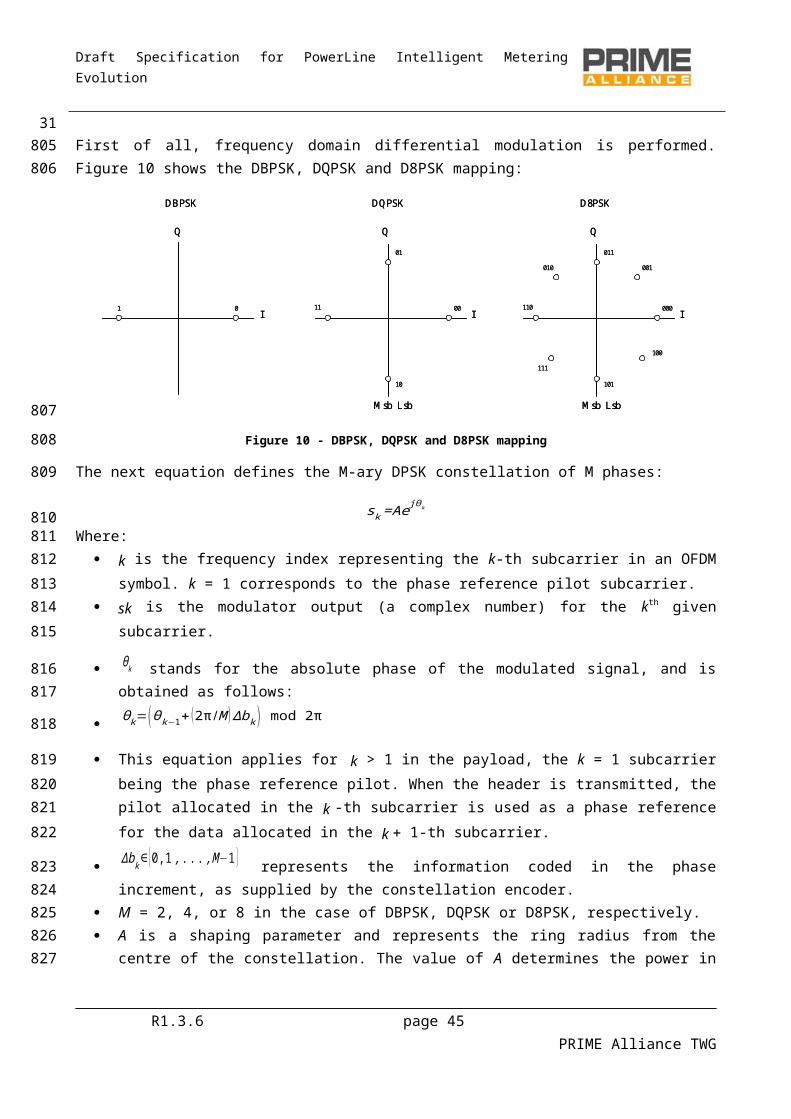
Draft Specification for PowerLine Intelligent Metering Evolution
MA
C
PHY
PHY_XXX.set
PHY_XXX.confirm
MA
C
PHY
PHY_XXX.get
PHY_XXX.confirm
Figure 17 – Overview of PHY Control Plane Primitives
Table 4 - Fields associated with PHY Control Plane Primitives
Field set get confirmPHY_AGC X X XPHY_Timer X XPHY_CD X XPHY_NL X XPHY_SNR X XPHY_ZCT X X
3.10.3.2 PHY_AGC.set
3.10.3.2.1 Function
The PHY_AGC.set primitive is passed to the PHY layer entity by the MAC layer entity to set the Automatic Gain Mode of the PHY layer.
3.10.3.2.2 Structure
The semantics of this primitive are as follows:
PHY_AGC.set Mode, Gain.
The Mode parameter specifies whether or not the PHY layer operates in automatic gain mode. It may take one of two values:
0: Auto;
1: Manual.
The Gain parameter specifies the initial receiving gain in auto mode. It may take one of N values:
0: min_gain dB;
1: min_ gain + step dB;
2: min_ gain + 2*step dB;
…
R1.3.6 page 45 PRIME Alliance TWG
33
901
902
903
904
905
906907
908
909
910
911912
913
914
915
916
917
918
919
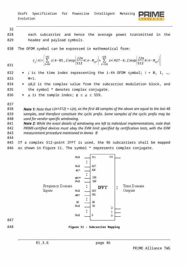
Draft Specification for PowerLine Intelligent Metering Evolution
N-1: min_ gain + (N-1)*step dB.
where min_ gain and N depend on the specific implementation. step is also an implementation issue but it shall not be more than 6 dB. The maximum Gain value min_ gain + (N-1)*step shall be at least 21 dB.
3.10.3.2.3 Use
The primitive is generated by the MAC layer when the receiving gain mode has to be changed.
3.10.3.3 PHY_AGC.get
3.10.3.3.1 Function
The PHY_AGC.get primitive is passed to the PHY layer entity by the MAC layer entity to get the Automatic Gain Mode of the PHY layer.
3.10.3.3.2 Structure
The semantics of this primitive are as follows:
PHY_AGC.get.
3.10.3.3.3 Use
The primitive is generated by the MAC layer when it needs to know the receiving gain mode that has been configured.
3.10.3.4 PHY_AGC.confirm
3.10.3.4.1 Function
The PHY_AGC.confirm primitive is passed by the PHY layer entity to the MAC layer entity in response to a PHY_AGC.set or PHY_AGC.get command.
3.10.3.4.2 Structure
The semantics of this primitive are as follows:
PHY_AGC.confirm Mode, Gain.
The Mode parameter specifies whether or not the PHY layer is configured to operate in automatic gain mode. It may take one of two values:
0: Auto;
1: Manual.
The Gain parameter specifies the current receiving gain. It may take one of N values:
0: min_gain dB;
1: min_gain + step dB;
2: min_gain + 2*step dB;
R1.3.6 page 46 PRIME Alliance TWG
34920
921922
923
924
925
926
927928
929
930
931
932
933934
935
936
937938
939
940
941
942943
944
945
946
947
948
949
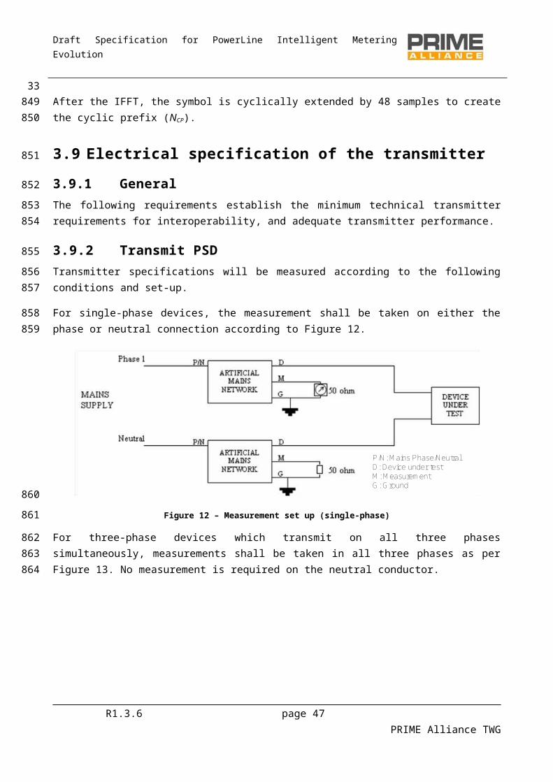
Draft Specification for PowerLine Intelligent Metering Evolution
…
N-1: min_gain + (N-1)*step dB.
where min_gain and N depend on the specific implementation. step is also an implementation issue but it shall not be more than 6 dB. The maximum Gain value min_gain + (N-1)*step shall be at least 21 dB.
3.10.3.5 PHY_Timer.get
3.10.3.5.1 Function
The PHY_Timer.get primitive is passed to the PHY layer entity by the MAC layer entity to get the time at which the transmission has to be started.
3.10.3.5.2 Structure
The semantics of this primitive are as follows:
PHY_Timer.get .
3.10.3.5.3 Use
The primitive is generated by the MAC layer to know the transmission start.
3.10.3.6 PHY_Timer.confirm
3.10.3.6.1 Function
The PHY_Timer.confirm primitive is passed to the MAC layer by the PHY layer entity entity in response to a PHY_Timer.get command.
3.10.3.6.2 Structure
The semantics of this primitive are as follows:
PHY_Timer.confirm Time.
The Time parameter is specified in 10s of microseconds. It may take values of between 0 and 220-1.
3.10.3.7 PHY_CD.get
3.10.3.7.1 Function
The PHY_CD.get primitive is passed to the PHY layer entity by the MAC layer entity to look for the carrier detect signal. The carrier detection algorithm shall be based on preamble detection and header recognition (see Section 3.4).
3.10.3.7.2 Structure
The semantics of this primitive are as follows:
PHY_CD.get .
R1.3.6 page 47 PRIME Alliance TWG
35950
951
952953
954
955
956957
958
959
960
961
962
963
964
965966
967
968
969
970
971
972
973974975
976
977
978

Draft Specification for PowerLine Intelligent Metering Evolution
3.10.3.7.3 Use
The primitive is generated by the MAC layer when it needs to know whether or not the physical medium is free.
3.10.3.8 PHY_CD.confirm
3.10.3.8.1 Function
The PHY_CD.confirm primitive is passed to the MAC layer entity by the PHY layer entity in response to a PHY_CD.get command.
3.10.3.8.2 Structure
The semantics of this primitive are as follows:
PHY_CD.confirm cd, rssi, Time, header.
The cd parameter may take one of two values:
0: no carrier detected;
1: carrier detected.
The rssi parameter is the Received Signal Strength Indication and refers to the preamble. It is only relevant when cd equals 1. It may take one of sixteen values:
0: ≤ 70 dBuV;
1: ≤ 72 dBuV;
2: ≤ 74 dBuV;
…
15: > 98 dBuV.
The Time parameter indicates the instant at which the present PPDU will finish. It is only relevant when cd equals 1. When cd equals 0, Time parameter will take a value of 0. If cd equals 1 but the duration of the whole PPDU is still not known (i.e. the header has not yet been processed), header parameter will take a value of 1 and time parameter will indicate the instant at which the header will finish, specified in 10s of microseconds. In any other case the value of Time parameter is the instant at which the present PPDU will finish, and it is specified in 10s of microseconds. Time parameter refers to an absolute point in time so it is referred to the system clock.
The header parameter may take one of two values:
1: if a preamble has been detected but the duration of the whole PPDU is not yet known from decoding the header;
0: in any other case.
R1.3.6 page 48 PRIME Alliance TWG
36979
980981
982
983
984985
986
987
988
989
990
991
992993
994
995
996
997
998
999100010011002100310041005
1006
10071008
1009

Draft Specification for PowerLine Intelligent Metering Evolution
3.10.3.9 PHY_NL.get
3.10.3.9.1 Function
The PHY_NL.get primitive is passed to the PHY layer entity by the MAC layer entity to get the floor noise level value.
3.10.3.9.2 Structure
The semantics of this primitive are as follows:
PHY_NL.get .
3.10.3.9.3 Use
The primitive is generated by the MAC layer when it needs to know the noise level present in the powerline.
3.10.3.10 PHY_NL.confirm
3.10.3.10.1 Function
The PHY_NL.confirm primitive is passed to the MAC layer entity by the PHY layer entity in response to a PHY_NL.get command.
3.10.3.10.2 Structure
The semantics of this primitive are as follows:
PHY_NL.confirm noise.
The noise parameter may take one of sixteen values:
0: ≤ 50 dBuV;
1: ≤ 53 dBuV;
2: ≤ 56 dBuV;
…
15: > 92 dBuV.
3.10.3.11 PHY_SNR.get
3.10.3.11.1 Function
The PHY_SNR.get primitive is passed to the PHY layer entity by the MAC layer entity to get the value of the Signal to Noise Ratio, defined as the ratio of measured received signal level to noise level of last received PPDU. The calculation of the SNR is described in Annex B.
3.10.3.11.2 Structure
The semantics of this primitive are as follows:
R1.3.6 page 49 PRIME Alliance TWG
371010
1011
10121013
1014
1015
1016
1017
10181019
1020
1021
10221023
1024
1025
1026
1027
1028
1029
1030
1031
1032
1033
1034
103510361037
1038
1039
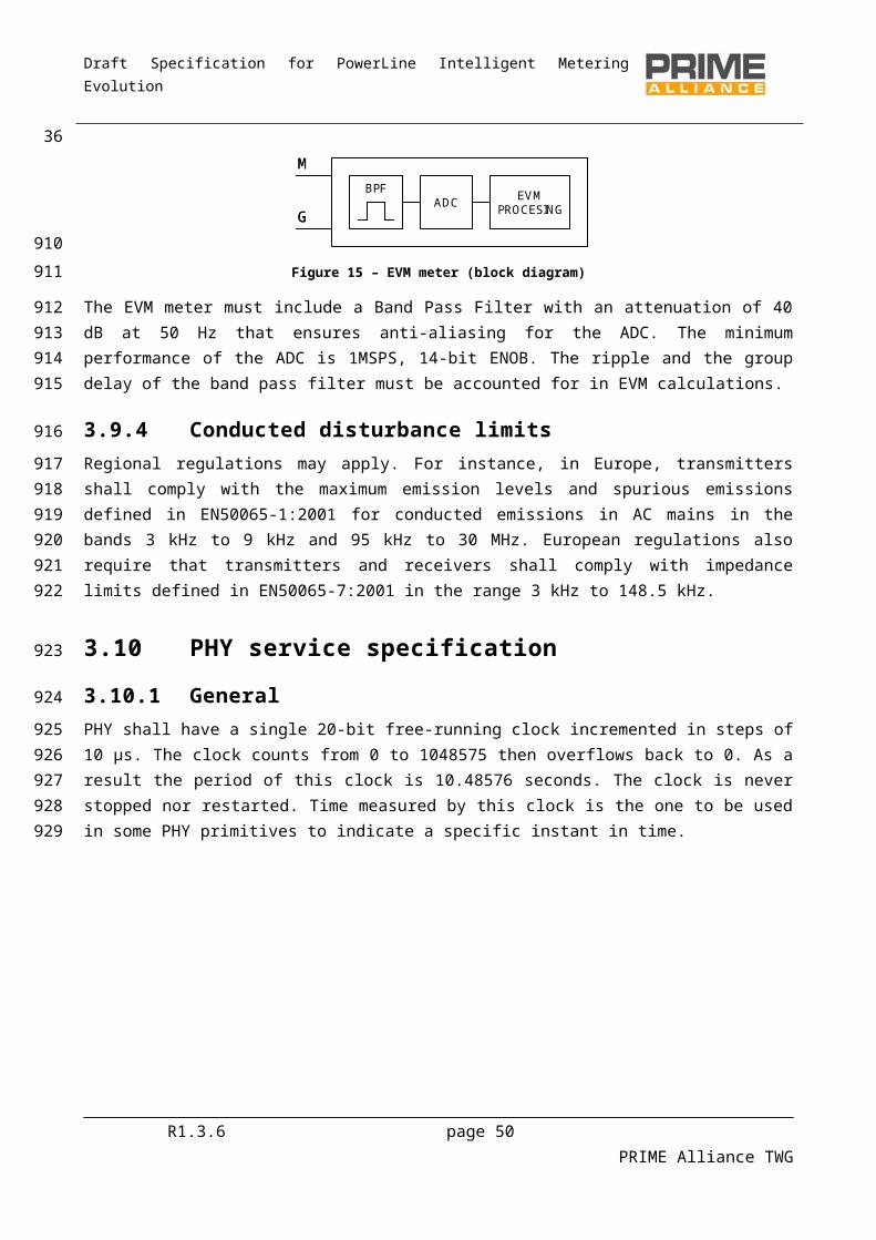
Draft Specification for PowerLine Intelligent Metering Evolution
PHY_SNR.get .
3.10.3.11.3 Use
The primitive is generated by the MAC layer when it needs to know the SNR in order to analyze channel characteristics and invoke robustness management procedures, if required.
3.10.3.12 PHY_SNR.confirm
3.10.3.12.1 Function
The PHY_SNR.confirm primitive is passed to the MAC layer entity by the PHY layer entity in response to a PHY_SNR.get command.
3.10.3.12.2 Structure
The semantics of this primitive are as follows:
PHY_SNR.confirmSNR.
The SNR parameter refers to the Signal to Noise Ratio, defined as the ratio of measured received signal level to noise level of last received PPDU. It may take one of eight values. The mapping of the 3-bit index to the actual SNR value, as calculated in Annex B, is given below:
0: ≤ 0 dB;
1: ≤ 3 dB;
2: ≤ 6 dB;
…
7: > 18 dB.
3.10.3.13 PHY_ZCT.get
3.10.3.13.1 Function
The PHY_ZCT.get primitive is passed to the PHY layer entity by the MAC layer entity to get the zero cross time of the mains and the time between the last transmission or reception and the zero cross of the mains.
3.10.3.13.2 Structure
The semantics of this primitive are as follows:
PHY_ZCT.get .
3.10.3.13.3 Use
The primitive is generated by the MAC layer when it needs to know the zero cross time of the mains, e.g. in order to calculate the phase to which the Node is connected.
R1.3.6 page 50 PRIME Alliance TWG
381040
1041
10421043
1044
1045
10461047
1048
1049
1050
105110521053
1054
1055
1056
1057
1058
1059
1060
10611062
1063
1064
1065
1066
10671068
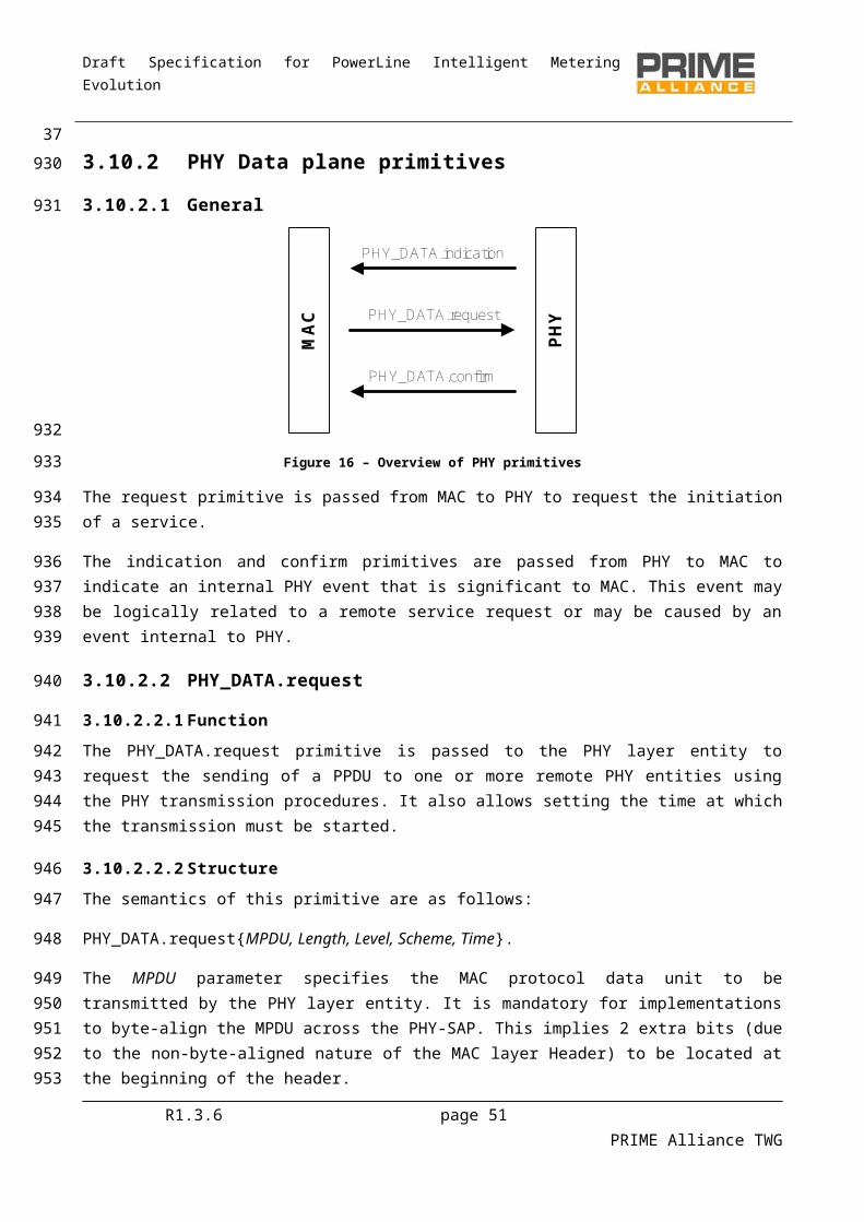
Draft Specification for PowerLine Intelligent Metering Evolution
3.10.3.14 PHY_ZCT.confirm
3.10.3.14.1 Function
The PHY_ZCT.confirm primitive is passed to the MAC layer entity by the PHY layer entity in response to a PHY_ZCT.get command.
3.10.3.14.2 Structure
The semantics of this primitive are as follows:
PHY_ZCT.confirm Time.
The Time parameter is the instant in time at which the last zero-cross event took place.
3.10.4 PHY Management primitives
3.10.4.1 General
PHY layer management primitives enable the conceptual PHY layer management entity to interface to upper layer management entities. Implementation of these primitives is optional. Please refer to Figure 17 to see the general structure of the PHY layer management primitives.
Table 5 - PHY layer management primitives
Primitive set get confirmPLME_RESET X XPLME_SLEEP X XPLME_RESUME X XPLME_TESTMODE X XPLME_GET X X
3.10.4.2 PLME_RESET.request
3.10.4.2.1 Function
The PLME_RESET.request primitive is invoked to request the PHY layer to reset its present functional state. As a result of this primitive, the PHY should reset all internal states and flush all buffers to clear any queued receive or transmit data. All the SET primitives are invoked by the PLME, and addressed to the PHY to set parameters in the PHY. The GET primitive is also sourced by the PLME, but is used only to read PHY parameters
3.10.4.2.2 Structure
The semantics of this primitive are as follows:
PLME_RESET.request.
R1.3.6 page 51 PRIME Alliance TWG
391069
1070
10711072
1073
1074
1075
1076
1077
1078
10791080108110821083
1084
1085
1086
10871088108910901091
1092
1093
1094
Draft Specification for PowerLine Intelligent Metering Evolution
3.10.4.2.3 Use
The upper layer management entities will invoke this primitive to tackle any system level anomalies that require aborting any queued transmissions and restart all operations from initialization state.
3.10.4.3 PLME_RESET.confirm
3.10.4.3.1 Function
The PLME_RESET.confirm is generated in response to a corresponding PLME_RESET.request primitive. It provides indication if the requested reset was performed successfully or not.
3.10.4.3.2 Structure
The semantics of this primitive are as follows:
PLME_RESET.confirmResult.
The Result parameter shall have one of the following values:
0: Success;
1: Failure. The requested reset failed due to internal implementation issues.
3.10.4.3.3 Use
The primitive is generated in response to a PLME_RESET.request.
3.10.4.4 PLME_SLEEP.request
3.10.4.4.1 Function
The PLME_SLEEP.request primitive is invoked to request the PHY layer to suspend its present activities including all reception functions. The PHY layer should complete any pending transmission before entering into a sleep state.
3.10.4.4.2 Structure
The semantics of this primitive are as follows:
PLME_SLEEP.request.
3.10.4.4.3 Use
Although this specification pertains to communication over power lines, it may still be objective of some applications to optimize their power consumption. This primitive is designed to help those applications achieve this objective.
3.10.4.5 PLME_SLEEP.confirm
3.10.4.5.1 Function
The PLME_SLEEP.confirm is generated in response to a corresponding PLME_SLEEP.request primitive and provides information if the requested sleep state has been entered successfully or not.
R1.3.6 page 52 PRIME Alliance TWG
401095
10961097
1098
1099
11001101
1102
1103
1104
1105
1106
1107
1108
1109
1110
1111
111211131114
1115
1116
1117
1118
111911201121
1122
1123
11241125
Draft Specification for PowerLine Intelligent Metering Evolution
3.10.4.5.2 Structure
The semantics of this primitive are as follows:
PLME_SLEEP.confirmResult.
The Result parameter shall have one of the following values:
0: Success;
1: Failure. The requested sleep failed due to internal implementation issues;
2: PHY layer is already in sleep state.
3.10.4.5.3 Use
The primitive is generated in response to a PLME_SLEEP.request
3.10.4.6 PLME_RESUME.request
3.10.4.6.1 Function
The PLME_RESUME.request primitive is invoked to request the PHY layer to resume its suspended activities. As a result of this primitive, the PHY layer shall start its normal transmission and reception functions.
3.10.4.6.2 Structure
The semantics of this primitive are as follows:
PLME_RESUME.request.
3.10.4.6.3 Use
This primitive is invoked by upper layer management entities to resume normal PHY layer operations, assuming that the PHY layer is presently in a suspended state as a result of previous PLME_SLEEP.request primitive.
3.10.4.7 PLME_RESUME.confirm
3.10.4.7.1 Function
The PLME_RESUME.confirm is generated in response to a corresponding PLME_RESUME.request primitive and provides information about the requested resumption status.
3.10.4.7.2 Structure
The semantics of this primitive are as follows:
PLME_RESUME.confirmResult.
The Result parameter shall have one of the following values:
0: Success;
R1.3.6 page 53 PRIME Alliance TWG
411126
1127
1128
1129
1130
1131
1132
1133
1134
1135
1136
113711381139
1140
1141
1142
1143
114411451146
1147
1148
11491150
1151
1152
1153
1154
1155
Draft Specification for PowerLine Intelligent Metering Evolution
1: Failure. The requested resume failed due to internal implementation issues;
2: PHY layer is already in fully functional state.
3.10.4.7.3 Use
The primitive is generated in response to a PLME_RESUME.request
3.10.4.8 PLME_TESTMODE.request
3.10.4.8.1 Function
The PLME_TESTMODE.request primitive is invoked to enter the Phy layer to a test mode (specified by the mode parameter). Specific functional mode out of the various possible modes is provided as an input parameter. Following receipt of this primitive, the PHY layer should complete any pending transmissions in its buffer before entering the requested Test mode.
3.10.4.8.2 Structure
The semantics of this primitive are as follows:
PLME_TESTMODE.requestenable, mode, modulation, pwr_level.
The enable parameter starts or stops the Test mode and may take one of two values:
0: stop test mode and return to normal functional state;
1: transit from present functional state to Test mode.
The mode parameter enumerates specific functional behavior to be exhibited while the PHY is in Test mode. It may have either of the two values.
0: continuous transmit;
1: transmit with 50% duty cycle.
The modulation parameter specifies which modulation scheme is used during transmissions. It may take any of the following 8 values:
0: DBPSK;
1: DQPSK;
2: D8PSK;
3: Not used;
4: DBPSK + Convolutional Code;
5: DQPSK + Convolutional Code;
6: D8PSK + Convolutional Code;
7: Not used.R1.3.6 page 54 PRIME Alliance TWG
421156
1157
1158
1159
1160
1161
1162116311641165
1166
1167
1168
1169
1170
1171
11721173
1174
1175
11761177
1178
1179
1180
1181
1182
1183
1184
1185

Draft Specification for PowerLine Intelligent Metering Evolution
The pwr_level parameter specifies the relative level at which the test signal is transmitted. It may take either of the following values:
0: Maximal output level (MOL);
1: MOL -3 dB;
2: MOL -6 dB;
…
7: MOL -21 dB;
3.10.4.8.3 Use
This primitive is invoked by management entity when specific tests are required to be performed.
3.10.4.9 PLME_TESTMODE.confirm
3.10.4.9.1 Function
The PLME_TESTMODE.confirm is generated in response to a corresponding PLME_TESTMODE.request primitive to indicate if transition to Testmode was successful or not.
3.10.4.9.2 Structure
The semantics of this primitive are as follows:
PLME_TESTMODE.confirmResult.
The Result parameter shall have one of the following values:
0: Success;
1: Failure. Transition to Testmode failed due to internal implementation issues;
2: PHY layer is already in Testmode.
3.10.4.9.3 Use
The primitive is generated in response to a PLME_TESTMODE.request
3.10.4.10 PLME_GET.request
3.10.4.10.1 Function
The PLME_GET.request queries information about a given PIB attribute.
3.10.4.10.2 Structure
The semantics of this primitive is as follows:
PLME_GET.requestPIBAttribute
R1.3.6 page 55 PRIME Alliance TWG
4311861187
1188
1189
1190
1191
1192
1193
1194
1195
1196
11971198
1199
1200
1201
1202
1203
1204
1205
1206
1207
1208
1209
1210
1211
1212
1213

Draft Specification for PowerLine Intelligent Metering Evolution
The PIBAttribute parameter identifies specific attribute as enumerated in Id fields of tables that enumerate PIB attributes (Section 6.2.2).
3.10.4.10.3 Use
This primitive is invoked by the management entity to query one of the available PIB attributes.
3.10.4.11 PLME_GET.confirm
3.10.4.11.1 Function
The PLME_GET.confirm primitive is generated in response to the corresponding PLME_GET.request primitive.
3.10.4.11.2 Structure
The semantics of this primitive is as follows:
PLME_GET.confirmstatus, PIBAttribute, PIBAttributeValue
The status parameter reports the result of requested information and may have one of the values shown in Table 6.
Table 6 - Values of the status parameter in PLME_GET.confirm primitive
Result Description
Done = 0 Parameter read successfully
Failed =1 Parameter read failed due to internal implementation reasons.
BadAttr=2 Specified PIBAttribute is not supported
The PIBAttribute parameter identifies specific attribute as enumerated in Id fields of tables that enumerate PIB attributes (Section 6.2.2).
The PIBAttributeValue parameter specifies the value associated with given PIBAttribute.
3.10.4.11.3 Use
This primitive is generated by PHY layer in response to a PLME_GET.request primitive.
R1.3.6 page 56 PRIME Alliance TWG
4412141215
1216
1217
1218
1219
12201221
1222
1223
1224
12251226
1227
1228
12291230
1231
1232
1233
Draft Specification for PowerLine Intelligent Metering Evolution
4 MAC layer
4.1 OverviewA Subnetwork can be logically seen as a tree structure with two types of Nodes: the Base Node and Service Nodes.
Base Node: It is at the root of the tree structure and it acts as a master Node that provides all Subnetwork elements with connectivity. It manages the Subnetwork resources and connections. There is only one Base Node in a Subnetwork. The Base Node is initially the Subnetwork itself, and any other Node should follow a Registration process to enroll itself on the Subnetwork.
Service Node: They are either leaves or branch points of the tree structure. They are initially in a Disconnected functional state and follow the Registration process in 4.6.1 to become part of the Subnetwork. Service Nodes have two functions in the Subnetwork: keeping connectivity to the Subnetwork for their Application layers, and switching other Nodes’ data to propagate connectivity.
Devices elements that exhibit Base Node functionality continue to do so as long as they are not explicitly reconfigured by mechanisms that are beyond the scope of this specification. Service Nodes, on the other hand, change their behavior dynamically from “Terminal” functions to “Switch” functions and vice-versa. The changing of functional states occurs in response to certain pre-defined events on the network. Figure18 shows the functional state transition diagram of a Service Node.
The three functional states of a Service Node are Disconnected, Terminal and Switch:
Disconnected: This is the initial functional state for all Service Nodes. When Disconnected, a Service Node is not able to communicate data or switch other Nodes’ data; its main function is to search for a Subnetwork within its reach and try to register on it.
Terminal: When in this functional state a Service Node is able to establish connections and communicate data, but it is not able to switch other Nodes’ data.
Switch: When in this functional state a Service Node is able to perform all Terminal functions. Additionally, it is able to forward data to and from other Nodes in the same Subnetwork. It is a branch point on the tree structure.
Switch
Terminal
Pro
mot
e Dem
ote
Disconnected
Unregister
RegisterUnregister
Figure 18 - Service Node states
R1.3.6 page 57 PRIME Alliance TWG
45
1234
1235
12361237
12381239124012411242124312441245
12461247124812491250
1251
12521253125412551256125712581259
1260
1261
Draft Specification for PowerLine Intelligent Metering Evolution
The events and associated processes that trigger changes from one functional state to another are:
Registration: the process by which a Service Node includes itself in the Base Node’s list of registered Nodes. Its successful completion means that the Service Node is part of a Subnetwork. Thus, it represents the transition between Disconnected and Terminal.
Unregistration: the process by which a Service Node removes itself from the Base Node’s list of registered Nodes. Unregistration may be initiated by either of Service Node or Base Node. A Service Node may unregister itself to find a better point of attachment i.e. change Switch Node through which it is attached to the network. A Base Node may unregister a registered Service Node as a result of failure of any of the MAC procedures. Its successful completion means that the Service Node is Disconnected and no longer part of a Subnetwork;
Promotion: the process by which a Service Node is qualified to switch (repeat, forward) data traffic from other Nodes and act as a branch point on the Subnetwork tree structure. A successful promotion represents the transition between Terminal and Switch. When a Service Node is Disconnected it cannot directly transition to Switch;
Demotion: the process by which a Service Node ceases to be a branch point on the Subnetwork tree structure. A successful demotion represents the transition between Switch and Terminal.
4.2 Addressing
4.2.1 GeneralEach Node has a 48-bit universal MAC address, defined in IEEE Std 802-2001 and called EUI-48. Every EUI-48 is assigned during the manufacturing process and it is used to uniquely identify a Node during the Registration process.
The EUI-48 of the Base Node uniquely identifies its Subnetwork. This EUI-48 is called the Subnetwork Address (SNA).
The Switch Identifier (LSID) is a unique 8-bit identifier for each Switch Node inside a Subnetwork. The Subnetwork Base Node assigns an LSID during the promotion process. A Switch Node is universally identified by the SNA and LSID. LSID = 0x00 is reserved for the Base Node. LSID = 0xFF is reserved to mean “unassigned” or “invalid” in certain specific fields (see Table 19).). This special use of the 0xFF value is always made explicit when describing those fields and it shall not be used in any other field.
During its Registration process, every Service Node receives a 14-bit Local Node Identifier (LNID). The LNID identifies a single Service Node among all Service Nodes that directly depend on a given Switch. The combination of a Service Node’s LNID and SID (its immediate Switch’s LSID) forms a 22-bit Node Identifier (NID). The NID identifies a single Service Node in a given Subnetwork. LNID = 0x0000 cannot be assigned to a Terminal, as it refers to its immediate Switch. LNID = 0x3FFF is reserved for broadcast and multicast traffic (see section 4.2.3 for more information). In certain specific fields, the LNID = 0x3FFF may also be used as “unassigned” or “invalid” (see Table 7 and Table 15). This special use of the 0x3FFF value is always made explicit when describing the said fields and it shall not be used in this way in any other field.
During connection establishment a 9-bit Local Connection Identifier (LCID) is reserved. The LCID identifies a single connection in a Node. The combination of NID and LCID forms a 31-bit Connection Identifier (CID).
R1.3.6 page 58 PRIME Alliance TWG
461262
126312641265126612671268126912701271127212731274127512761277
1278
1279
128012811282
12831284
12851286128712881289
12901291129212931294129512961297
12981299
Draft Specification for PowerLine Intelligent Metering Evolution
The CID identifies a single connection in a given Subnetwork. Any connection is universally identified by the SNA and CID. LCID values are allocated with the following rules:
LCID=0x000 to 0x0FF, for connections requested by the Base Node. The allocation shall be made by the Base Node.
LCID=0x100 to 0x1FF, for connections requested by a Service Node. The allocation shall be made by a Service Node.
The full addressing structure and field lengths are shown in Figure 19
SNA LSID LNID LCID
MSB 48 bits 8 bits 14 bits 9 bits
LSBNID (22 bits)
CID (31 bits)
Figure 19 - Addressing Structure
When a Service Node in Terminal state starts promotion process, the Base Node allocates a unique switch identifier which is used by this device after transition to switch state as SID of this switch. The promoted Service Node continues to use the same NID that it used before promotion i.e. it maintains SID of its next level switch for addressing all traffic generated/destined to its local application processes. To maintain distinction between the two switch identifiers, the switch identifier allocated to a Service Node during its promotion is referred to as Local Switch Identifier (LSID). Note that the LSID of a switch device will be SID of devices that connects to the Subnetwork through it.
Each Service Node has a level in the topology tree structure. Service Nodes which are directly connected to the Base Node have level 0. The level of any Service Node not directly connected to the Base Node is the level of its immediate Switch plus one.
4.2.2 Example of address resolution Figure 20 shows an example where Disconnected Service Nodes are trying to register on the Base Node. In this example, addressing will have the following nomenclature: (SID, LNID). Initially, the only Node with an address is Base Node A, which has an NID=(0, 0).
A: Base Node
B:Disconnected C:Disconnected
S=(0, 0)
D:Disconnected E:Disconnected
F:Disconnected G:Disconnected H:Disconnected
Figure 20 – Example of address resolution: phase 1
R1.3.6 page 59 PRIME Alliance TWG
4713001301
13021303
13041305
1306
1307
1308
1309131013111312131313141315
131613171318
1319
132013211322
13231324
Draft Specification for PowerLine Intelligent Metering Evolution
Every other Node of the Subnetwork will try to register on the Base Node. Only B, C, D and E Nodes are able to register on this Subnetwork and get their NIDs. Figure 21 shows the status of Nodes after the Registration process. Since they have registered on the Base Node, they get the SID of the Base Node and a unique LNID. The level of newly registered Nodes is 0 because they are connected directly to the Base Node.
T=(0, 1)
A: Base Node
B: Terminal C: Terminal
S=(0, 0)
T=(0, 3)D: Terminal
T=(0, 4) T=(0, 2)E: Terminal
F:Disconnected G:Disconnected H:Disconnected
Level = 0
Figure 21 – Example of address resolution: phase 2
Nodes F, G and H cannot connect directly to the Base Node, which is currently the only Switch in the Subnetwork. F, G and H will send PNPDU broadcast requests, which will result in Nodes B and D requesting promotion for themselves in order to extend the Subnetwork range. During promotion, they will both be assigned unique SIDs. Figure 22 shows the new status of the network after the promotion of Nodes B and D. Each Switch Node will still use the NID that was assigned to it during the Registration process for its own communication as a Terminal Node. The new SID shall be used for all switching functions.
T=(0, 3)
A: Base Node
B: Switch C: Terminal
S=(0, 0)
T=(0, 3)S=(1, 0)D: Switch
T=(0, 4)S=(2, 0) T=(0, 2)E: Terminal
F:Disconnected G:Disconnected H:Disconnected
Level = 0
Figure 22 – Example of address resolution: phase 3
On completion of the B and D promotion process, Nodes F, G and H shall start their Registration process and have a unique LNID assigned. Every Node on the Subnetwork will then have a unique NID to communicate like a Terminal, and Switch Nodes will have unique SIDs for switching purposes. The level of newly registered Nodes is 1 because they register with level 0 Nodes. On the completion of topology resolution and address allocation, the example Subnetwork would be as shown in Figure 23
R1.3.6 page 60 PRIME Alliance TWG
4813251326132713281329
13301331
133213331334133513361337
13381339
13401341134213431344

Draft Specification for PowerLine Intelligent Metering Evolution
T=(0, 1)
A: Base Node
B: Switch C: Terminal
S=(0, 0)
T=(0, 3)S=(1, 0)D: Switch
T=(0, 4)S=(2, 0) T=(0, 2)E: Terminal
T=(1, 2)F: Terminal G: Terminal
T=(1, 1)H: Terminal
T=(2, 1)
Level = 0
Level = 1
Figure 23 – Example of address resolution: phase 4
4.2.3 Broadcast and multicast addressingMulticast and broadcast addresses are used for communicating data to multiple Nodes. There are several broadcast and multicast address types, depending on the context associated with the traffic flow. Table 7 describes different broadcast and multicast addressing types and the SID and LNID fields associated with each one.
Table 7 - Broadcast and multicast address
Type LNID Description
Broadcast 0x3FFF Using this address as a destination, the packets should reach every Node of the Subnetwork.
Multicast 0x3FFE This type of address refers to multicast groups. The multicast group is defined by the LCID.
Unicast not 0x3FFF not 0x3FFE The address of this type refers to the only Node of the Subnetwork whose SID and LNID match the address fields.
4.3 MAC functional description
4.3.1 Service Node start-upA Service Node is initially Disconnected. The only functions that may be performed in a Disconnected functional state are: reception of any beacons on the channel and sending of the PNPDUs. Each Service Node shall maintain a Switch table that is updated with the reception of a beacon from any new Switch Node. Based on local implementation policies, a Service Node may select any Switch Node from the Switch table and proceed with the Registration process with that Switch Node. The criterion for selecting a Switch Node from the Switch table is beyond the scope of this specification.
A Service Node shall listen on the channel for at least macMinSwitchSearchTime before deciding that no beacon is being received. It may optionally add some random variation to macMinSwitchSearchTime, but this variation cannot be more than 10% of macMinSwitchSearchTime. If no beacons are received in this time, the Service Node shall broadcast a PNPDU. The PNPDU shall be broadcast with the most robust modulation scheme to ensure maximum coverage. A Service Node seeking promotion of any of the Terminal Nodes in its proximity shall not transmit more than macMaxPromotionPdu PNPDUs per
R1.3.6 page 61 PRIME Alliance TWG
49
13451346
1347
1348134913501351
1352
1353
1354
135513561357135813591360
136113621363136413651366

Draft Specification for PowerLine Intelligent Metering Evolution
macPromotionPduTxPeriod units of time. The Service Nodes shall also ensure that the broadcast of PNPDUs is randomly spaced. There must always be a random time separation between successive broadcasts.
So as not to flood the network with PNPDUs, especially in cases where several devices are powered up at the same time, the Terminal Nodes shall reduce the PNPDU transmission rate by a factor of PNPDUs received from other sources. For example, if a Node receives one PNPDU when it is transmitting its own PNPDUs, it shall reduce its own transmissions to no more than macMaxPromotionPdu/2 per macPromotionPduTxPeriod units of time. Likewise, if it receives PNPDUs from two different sources, it shall slow down its rate to no more than macMaxPromotionPdu/3 per macPromotionPduTxPeriod units of time.
On the selection of a specific Switch Node, a Service Node shall start a Registration process by transmitting the REG control packet (4.4.5.3) to the Base Node. The Switch Node through which the Service Node intends to carry out its communication is indicated in the REG control packet.
4.3.2 Starting and maintaining SubnetworksBase Nodes are primarily responsible for setting up and maintaining a Subnetwork. In order to execute the latter, the Base Node shall perform the following:
Beacon transmission. The Base Node and all the Switch Nodes on the Subnetwork shall broadcast beacons at fixed intervals of time. The Base Node shall always transmit exactly one beacon per frame. Switch Nodes shall transmit beacons with a frequency prescribed by the Base Node at the time of their promotion.
Promotion and demotion of Terminals and switches. All promotion requests generated by Terminal Nodes upon reception of PNPDUs are directed to the Base Node. The Base Node maintains a table of all the Switch Nodes on the Subnetwork and allocates a unique SID to new incoming requests. Upon reception of multiple promotion requests, the Base Node can, at its own discretion, reject some of the requests. Likewise, the Base Node is responsible for demoting registered Switch Nodes. The demotion may either be initiated by the Base Node (based on an implementation-dependent decision process) or be requested by the Switch Node itself.
Registration management. The Base Node receives Registration requests from all new Nodes trying to be part of the Subnetwork it manages. The Base Node shall process each Registration request it receives and respond with an accept or reject message. When the Base Node accepts the registration of a service node, it shall allocate an unique NID to it to be used for all subsequent communication on the Subnetwork. Likewise, the Base Node is responsible for deregistering any registered Service Node. The unregistration may be initiated by the Base Node (based on an implementation-dependent decision process) or requested by the Service Node itself.
Connection setup and management: The MAC layer specified in this document is connection-oriented, implying that data exchange is necessarily preceded by connection establishment. The Base Node is always required for all connections on the Subnetwork, either as an end point of the connection or as a facilitator (direct connections; Section 4.3.6) of the connection.
Channel access arbitration. The usage of the channel by devices conforming to this specification may be controlled and contention-free at certain times and open and contention-based at others. The Base Node prescribes which usage mechanism shall be in force at what time and for how long. Furthermore, the Base Node shall be responsible for assigning the channel to specific devices during contention-free access periods.
R1.3.6 page 62 PRIME Alliance TWG
5013671368
136913701371137213731374
137513761377
1378
13791380
138113821383138413851386138713881389139013911392139313941395139613971398139914001401140214031404140514061407

Draft Specification for PowerLine Intelligent Metering Evolution
Distribution of random sequence for deriving encryption keys. When using Security Profile 1 (see 4.3.8.1), all control messages in this MAC specification shall be encrypted before transmission. Besides control messages, data transfers may be optionally encrypted as well. The encryption key is derived from a 128-bit random sequence. The Base Node shall periodically generate a new random sequence and distribute it to the entire Subnetwork, thus helping to maintain the Subnetwork security infrastructure.
Multicast group management. The Base Node shall maintain all multicast groups on the Subnetwork. This shall require the processing of all join and leave requests from any of the Service Nodes and the creation of unsolicited join and leave messages from Base Node application requests.
Additional information regarding promotion and connection procedures can be found in sections 4.6.3 and 4.6.6.
4.3.3 Channel Access
4.3.3.1 General
Devices on a Subnetwork access the channel based on specific guidelines laid down in this section. Time is divided into composite units of abstraction for channel usage, called MAC Frames. The Service Nodes and Base Node on a Subnetwork can access the channel in the Shared Contention Period (SCP) or request a dedicated Contention-Free Period (CFP).
CFP channel access needs devices to request allocation from the Base Node. Depending on channel usage status, the Base Node may grant access to the requesting device for specific duration or deny the request.
SCP channel access does not require any arbitration. However, the transmitting devices need to respect the SCP timing boundaries in a MAC Frame. The composition of a MAC Frame in terms of SCP and CFP is communicated in every frame as part of beacon.
A MAC Frame is comprised of one or more Beacons, one Shared-Contention Period and zero or one Contention-Free Period (CFP). When present, the length of the CFP is indicated in the BPDU.
CFPSCP
Beacon 0
Beacon 1
Beacon 2
Beacon 3
Beacon 4
Figure 24 – Structure of a MAC Frame
4.3.3.2 Beacon
4.3.3.2.1 General
A BPDU is transmitted by the Base Node every (MACFrameLength – MACBeaconLength) symbols. The Switch Nodes also transmit BPDU to maintain their part of the Subnetwork. They transmit BPDUs at regular times, but the transmission frequency does not need to be the same as that of the Base Node, i.e. a Switch Node may not transmit its BPDU in every frame.
A beacon is always MACBeaconLength symbols long. This length is the beacon duration excluding the PHY PREAMBLE overhead. Since the BPDU is to be received by all devices in the originating Switch domain, it is
R1.3.6 page 63 PRIME Alliance TWG
51140814091410141114121413141414151416
14171418
1419
1420
1421142214231424
14251426
142714281429
14301431
14321433
1434
1435
1436143714381439
14401441
Draft Specification for PowerLine Intelligent Metering Evolution
transmitted with the most robust PHY modulation scheme and FEC coding at the maximum output power level implemented in the device. Details of the BPDU structure and contents are given in 4.4.4.
All Service Nodes shall track beacons as explained in 4.3.4.1.
4.3.3.2.2 Beacon-slots
A single frame may contain macBeaconsPerFrame BPDUs. The unit of time in which a BPDU is transmitted, is referred to as a beacon-slot. All beacon-slots are located at the beginning of a frame, as shown in Figure24 above. The first beacon-slot in every frame is reserved for the Base Node. The number of beacon-slots in a frame may change from one frame to another and is indicated by the Base Node in its BPDU.
The Switch Nodes are allocated a beacon-slot at the time of their promotion. Following the PRO control packet, the Base Node transmits the BSI control packet that would list specific details on which beacon-slot should be used by the new Switch device.
The number of beacon-slots in a frame should be increased from 1 to at least 2 on the promotion of the first Switch device on a Subnetwork by the Base Node. Similarly, a Base Node cannot decrease the number of beacon-slots in the Subnetwork to 1 when there is a Switch Node on its Subnetwork.
With the Registration of each new Switch on the Subnetwork, the Base Node may change the beacon-slot or BPDU transmission frequency (or both) of already registered Switch devices. When such a change occurs, the Base Node transmits a Beacon Slot Information (BSI) control packet to each individual Switch device that is affected. The Switch device addressed in the BSI packet sends an acknowledgement back to the Base Node. Switch devices are required to relay the BSI control packet that is addressed to Switch devices connected through them. During the reorganization of beacon-slots, if there is a change in the beacon-slot count per frame, the Base Node should transmit an FRA (FRAme) control packet to the entire Subnetwork. The FRA control packet is an indication of change in the overall Frame structure. In this specific case, it would imply an increase in SCP slots and a decrease in the number of Beacon Slots.
Switch devices that receive an FRA control packet should relay it to their entire control domain because FRA packets are broadcast information about changes to frame structures.
This is required for the entire Subnetwork to have a common understanding of frame structure, especially in regions where the controlling Switch devices transmit BPDUs at frequencies below once per frame.
Figure 25 below shows a sample beacon-slot change sequence for an existing Switch device. The example shows a beacon-slot change triggered by the promotion of a Terminal device (PRO_ACK). In this case, the promotion is followed by a change in both the number of beacon-slots per frame and of the specific beacon-slot parameters already allocated to a Switch.
R1.3.6 page 64 PRIME Alliance TWG
5214421443
1444
1445
1446144714481449
145014511452
145314541455
145614571458145914601461146214631464
14651466
14671468
1469147014711472
Draft Specification for PowerLine Intelligent Metering Evolution
Terminal Base Node Switch PRO_ACK
FRA_BCN_IND
BSI_IND
BSI_ACK
FRA_BCN_IND BSI_IND
BSI_ACK
Figure 25 – Example of control packet sequencing following a promotion
4.3.3.2.3 Beacon-slot allocation policy
The Beacon Slot allocation policy shall ensure that during promotion a Service Node never receives a BSI control packet that enforces it to transmit a beacon consecutive to every beacon of the Node it is registered to.
This behavior shall be ensured if the BSI information follows one, or more, of the following rules (BCN represents the information of the beacons the Service Node is registered to):
BSI.SLT is not consecutive to BCN.POS; BSI.SEQ is not equal to any BCN.SEQ in a superframe; BSI.FRQ is greater than BCN.FRQ.
4.3.3.2.4 Beacon Superframes
When changing the frame structure, to add or remove Beacon Slots, or to change which Beacon Slot a Switch should use, it is necessary to indicate when such a change should occur. All Nodes must change at the same time otherwise there will be collisions with the beacons etc.
To solve this problem a Beacon superframe is defined. Each Beacon contains a 5 bit sequence number. Thus 32 frames form a superframe. Any messages which contain changes to the structure or usage of the frame include a sequence number for when the change should occur. The changes requested should only happen when the beacon sequence number matches the sequence number in the change request.
4.3.3.3 Shared-contention period
4.3.3.3.1 General
Shared-contention period (SCP) is the time when any of the devices on the Subnetwork can transmit data. The SCP starts immediately after the end of the beacon-slot(s) in a frame. Collisions resulting from simultaneous attempt to access the channel are avoided by the CSMA-CA mechanism specified in this section.
The length of the SCP may change from one frame to another and is indicated by information in the Beacon. At all times, the SCP is at least MACMinSCPLength symbols long. The maximum permissible length of an SCP in a frame is (MACFrameLength – MACBeaconLength) symbols. Maximum length SCPs can only occur when there are no dedicated channel access grants to any of the devices (no CFP) on a Subnetwork that has no Switch Nodes (only one Beacon Slot).
R1.3.6 page 65 PRIME Alliance TWG
53
14731474
1475
147614771478
14791480
148114821483
1484
148514861487
1488148914901491
1492
1493
1494149514961497
14981499150015011502

Draft Specification for PowerLine Intelligent Metering Evolution
The use of SCP is not restricted to frames in which beacons are received. In lower Levels of the Subnetwork, the controlling Switch Node may transmit beacons at a much lower frequency than once per frame. For these parts of the Subnetwork, the frame structure would still continue to be the same in frames where no beacons are transmitted. Thus, the Service Nodes in that segment may still use SCP at their discretion.
4.3.3.3.2 CSMA-CA algorithm
The CSMA-CA algorithm implemented in devices works as shown in the Figure 26.
Implementations start with a random backoff time (macSCPRBO) based on the priority of data queued for transmission. MACPriorityLevels levels of priority need to be defined in each implementation, with a lower value indicating higher priority. In the case of data aggregation, the priority of aggregate bulk is governed by the highest priority data it contains. The MacSCPRBO for a transmission attempt is give as below:
macSCPRBO = random (0, MIN ((2(Priority+txAttempts) +1), (macSCPLength/2)))
Before a backoff period starts, a device should ensure that the remaining SCP time is long enough to accommodate the backoff, the number of iterations for channel-sensing (based on data priority) and the subsequent data transmission. If this is not the case, backoff should be aborted till the SCP starts in the next frame. Aborted backoffs that start in a subsequent frame should not carry macSCPRBO values of earlier attempts. macSCPRBO values should be regenerated on the resumption of the transmission attempt in the SCP time of the next frame.
R1.3.6 page 66 PRIME Alliance TWG
541503150415051506
1507
1508
1509151015111512
1513
151415151516151715181519

Draft Specification for PowerLine Intelligent Metering Evolution
Figure 26 - Flow chart for CSMA-CA algorithm
On the completion of macSCPRBO symbol time, implementations perform channel-sensing. Channel sensing shall be performed one or more times depending on priority of data to be transmit. The number of times for which an implementation has to perform channel-sensing (macSCPChSenseCount) is defined by the priority of the data to be transmitted with the following relation:
macSCPChSenseCount = Priority + 1
and each channel sense should be separated by a 3ms delay.
When a channel is sensed to be idle on all macSCPChSenseCount occasions, an implementation may conclude that the channel status is idle and carry out its transmission immediately.
During any of the macSCPChSenseCount channel-sensing iterations, if the channel is sensed to be occupied, implementations should reset all working variables. The local counter tracking the number of times a
R1.3.6 page 67 PRIME Alliance TWG
55
15201521
1522152315241525
1526
1527
15281529
15301531
Draft Specification for PowerLine Intelligent Metering Evolution
channel is found to be busy should be incremented by one and the CSMA-CA process should restart by generating a new macSCPRBO. The remaining steps, starting with the backoff, should follow as above.
If the CSMA-CA algorithm restarts macSCPMaxTxAttempts number of times due to ongoing transmissions from other devices on the channel, the transmission shall abort by informing the upper layers of CSMA-CA failure.
4.3.3.3.3 MAC control packets
MAC control packets should be transmitted in the SCP with a priority of one. Refers to priorities in subsection 4.4.2.3
4.3.3.4 Contention-Free Period
Each MAC frame may optionally have a contention-free period where devices are allocated channel time on an explicit request to do so. If no device on a Subnetwork requests contention-free channel access, the CFP_ALC_REQ_S may be entirely absent and the MAC frame would comprise only SCP. All CFP_ALC_REQ_S requests coming from Terminal or Switch Nodes are addressed to the Base Node. Intermediate Switch Nodes along the transmission path merely act on the allocation decision by the Base Node. A single MAC frame may contain up to MACCFPMaxAlloc non-overlapping contention-free periods.
Base Nodes may allocate overlapping times to multiple requesting Service Nodes. Such allocations may lead to potential interference. Thus, a Base Node should make such allocations only when devices that are allocated channel access for concurrent usage are sufficiently separated.
Service Nodes make channel allocation request in a CFP MAC control packet. The Base Node acts on this request and responds with a request acceptance or denial. In the case of request acceptance, the Base Node shall respond with the location of allocation time within MAC frame, the length of allocation time and number of future MAC frames from which the allocation pattern will take effect. The allocation pattern remains effective unless there is an unsolicited location change of the allocation period from the Base Node (as a result of a channel allocation pattern reorganization) or the requesting Service Node sends an explicit de-allocation request using a CFP MAC control packet.
Changes resulting from action taken on a CFP MAC control message that impact overall MAC frame structure are broadcast to all devices using an FRA MAC control message.
In a multi level Subnetwork, when a Service Node that is not directly connected to the Base Node makes a request for CFP, the Base Node shall allocate CFPs to all the intermediate Switch Nodes so that the entire transit path from the source Service Node to Base has contention-free time-slots reserved. The Base Node shall transmit multiple CFP control packets. The first of these CFP_ALC_IND will be for the requesting Service Node. Each of the rest will be addressed to an intermediate Switch Node.
4.3.4 Tracking switches and peers
4.3.4.1 Tracking switches
Service Nodes should keep track of all neighboring Switch Nodes by maintaining a list of the beacons received. Such tracking shall keep a Node updated on reception signal quality from Switch Nodes other
R1.3.6 page 68 PRIME Alliance TWG
5615321533
153415351536
1537
15381539
1540
154115421543154415451546
154715481549
1550155115521553155415551556
15571558
15591560156115621563
1564
1565
15661567

Draft Specification for PowerLine Intelligent Metering Evolution
than the one to which it is connected, thus making it possible to change connection points (Switch Node) to the Subnetwork if link quality to the existing point of connectivity degrades beyond an acceptable level.
Note that such a change of point of connectivity may be complex for Switch Nodes because of devices connected through them. However, at certain times, network dynamics may justify a complex reorganization rather than continue with existing limiting conditions.
4.3.4.2 Tracking disconnected Nodes
Terminals shall process all received PNPDUs. When a Service Node is Disconnected, it doesn’t have information on current MAC frame structure so the PNPDUs may not necessarily arrive during the SCP. Thus, Terminals shall also keep track of PNPDUs during the CFP or beacon-slots.
On processing a received PNPDU, a Terminal Node may decide to ignore it and not generate any corresponding promotion request (PRO_REQ_S). A Terminal Node shall ignore no more than MACMaxPRNIgnore PNPDUs from the same device. Receiving multiple PNPDUs from the same device indicates that there is no other device in the vicinity of the Disconnected Node, implying that there will be no possibility of this new device connecting to any Subnetwork if the Terminal Node does not request promotion for itself.
4.3.5 Switching
4.3.5.1 General
On a Subnetwork, the Base Node cannot communicate with every Node directly. Switch Nodes relay traffic to/from the Base Node so that every Node on the Subnetwork is effectively able to communicate with the Base Node. Switch Nodes selectively forward traffic that originates from or is destined to one of the Service Nodes in its control hierarchy. All other traffic is discarded by Switches, thus optimizing traffic flow on the network.
Different names of MAC header and packets are used in this section. Please refer to the section 4.4.2 to find their complete specification.
4.3.5.2 Switching table
Each Switch Node maintains a table of other Switch Nodes that are connected to the Subnetwork through it. Maintaining this information is sufficient for switching because traffic to/from Terminal Nodes will also contain the identity of their respective Switch Nodes (PKT.SID). Thus, the switching function is simplified in that maintaining an exhaustive listing of all Terminal Nodes connected through it is not necessary.
Switch Nodes start with no entries in their switching table. The switching table is dynamically updated by keeping track of promotion and demotion control packets flowing on the network. A new entry is created for every promotion acknowledgement (PRO_ACK) that has a PKT.SID matching either the SID of the Switch Node itself or any of the existing entries in the switching table. Likewise, an entry corresponding to a PRO.NSID field is deleted when a demotion request is acknowledged (PRO_DEM_x).
R1.3.6 page 69 PRIME Alliance TWG
5715681569
157015711572
1573
157415751576
157715781579158015811582
1583
1584
15851586158715881589
15901591
1592
1593159415951596
15971598159916001601

Draft Specification for PowerLine Intelligent Metering Evolution
Figure 27 - Switching tables example
Figure 27 shows an example Subnetwork where entries in the switching table of individual Switch Nodes are highlighted. In this example, when Service Node G receives a PRO_REQ_B packet for promotion, it turns into a Switch Node. Its Switch identifier will be (PRO.NSID, 0) = (3, 0). The receipt and acceptance of PRO_REQ_B is acknowledged with a PRO_ACK by G. The intermediate Switch Node B will sniff HDR.DO=0, PKT.CTYPE=3, PKT.SID=1 and PRO.N=0, to conclude that this is a PRO_ACK from one of the Service Nodes in its own switching hierarchy. Node B will forward this packet towards the Base Node and it will add PRO.NSID to its switching table, as shown in Figure 28 .
Figure 28 - Fill in the switching table
Removing a Switch table entry is more complex because of retries. On reception of a demotion acknowledgement (PRO_DEM_x), the switching table entry corresponding to the LSID is marked as to be removed and a timer is started with a value of ((macMaxCtlReTx + 1) * macCtlReTxTimer) seconds. This timer ensures that all retransmit packets which might use the LSID have left the Subnetwork. When the timer expires the Switch table entry is removed
R1.3.6 page 70 PRIME Alliance TWG
58
16021603
1604160516061607160816091610
16111612
16131614161516161617
Draft Specification for PowerLine Intelligent Metering Evolution
4.3.5.3 Switching process
Switch Nodes forward traffic to their control domain in a selective manner. The received data shall fulfill the conditions listed below for it to be switched. If the conditions are not met, the data shall be silently discarded.
Downlink packets (HDR.DO=1) shall meet any of the following conditions in order to be switched:
Destination Node of the packet is connected to the Subnetwork through this Switch Node, i.e. PKT.SID is equal to this Switch Node’s SID or its switching table contains an entry for PKT.SID.
The packet has broadcast destination (PKT.LNID = 0x3FFF) and was sent by the Switch this Node is registered through (PKT.SID=SID of this Switch Node).
The packet has a multicast destination (PKT.LNID=0x3FFE), it was sent by the Switch this Node is registered through (PKT.SID=SID of this Switch Node) and at least one of the Service Nodes connected to the Subnetwork through this Switch Node is a member of the said multicast group, i.e. LCID specifies a group that is requested by any downstream Node in its hierarchy.
Uplink packets (HDR.DO=0) shall meet either of the following conditions in order to be switched:
The packet source Node is connected to the Subnetwork through this Switch Node, i.e. PKT.SID is equal to this Switch Node’s SID or its switching table contains an entry for PKT.SID.
The packet has a broadcast or multicast destination (PKT.LNID = 0x3FFF or 0x3FFE) and was transmitted by a Node registered through this Switch Node (PKT.SID=LSID of this Switch Node).
If a packet meets previous conditions, it shall be switched. For unicast packets, the only operation to be performed during switching is queuing it to be resent in a MAC PDU with the same HDR.DO.
In case of broadcast or multicast packets, the PKT.SID must be replaced with:
The Switch Node’s LSID for Downlink packets. The Switch Node’s SID for uplink packets.
4.3.5.4 Switching of broadcast packets
The switching of broadcast MAC frames operates in a different manner to the switching of unicast MAC frames. Broadcast MAC frames are identified by PKT.LNID=0x3FFF.
When HDR.DO=0, i.e. the packet is an uplink packet, it is unicast to the Base Node. A Switch which receives such a packet should apply the scope rules to ensure that it comes from a lower level and, if so, Switch it upwards towards the base. The rules given in section 4.3.5.3 must be applied.
When HDR.DO=1, i.e. the packet is a Downlink packet, it is broadcast to the next level. A Switch which receives such a packet should apply the scope rules to ensure that it comes from the higher level and, if so, switch it further to its Subnetwork. The most robust PHY modulation scheme and FEC coding at the maximum output power level implemented in the device should be used so that all the devices directly connected to the Switch Node can receive the packet. The rules given in section 4.3.5.3 must be applied. The Service Node should also pass the packet up to its MAC SAP to applications which have registered to receive broadcast packets using the MAC_JOIN service.
R1.3.6 page 71 PRIME Alliance TWG
591618
161916201621
1622
16231624162516261627162816291630
1631
1632163316341635
16361637
1638
16391640
1641
16421643
164416451646
1647164816491650165116521653
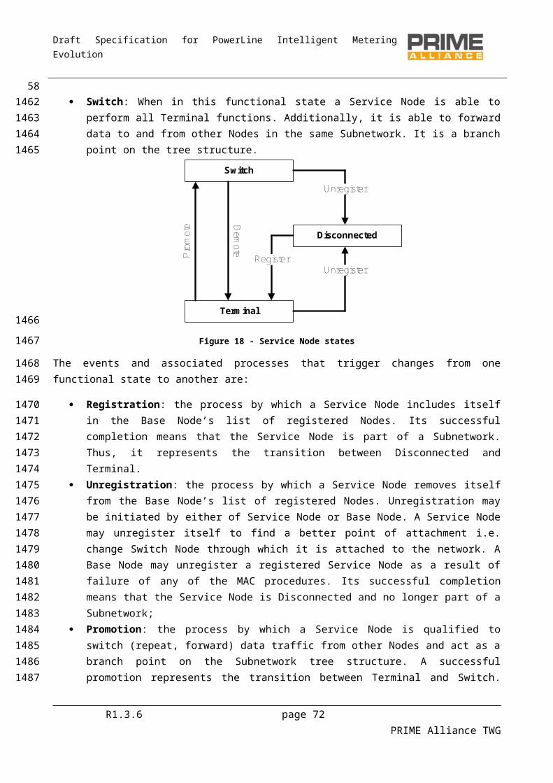
Draft Specification for PowerLine Intelligent Metering Evolution
When the Base Node receives a broadcast packet with HDR.DO=0, it should pass the packet up its MAC SAP to applications which have registered to receive broadcast packets. The Base Node should also transmit the packet as a Downlink packet, i.e. HDR.DO=1, using the most robust PHY modulation scheme and FEC coding at the maximum output power level and following the rules given in section 4.3.5.3.
4.3.5.5 Switching of multicast packets
4.3.5.5.1 General
Multicast packet switching operates in a very similar way to broadcast packet switching. Multicast is an extension of broadcast. If a switching Node does not implement multicasting, it should handle all multicast packets as broadcast packets.
Different names of MAC header and packets are use in this section. Refers to the section 4.4.2 to find proper definitions.
4.3.5.5.2 Multicast switching table
Switch Nodes which implement multicast should maintain a multicast switching table. This table contains a list of multicast group LCIDs that have members connected to the Subnetwork through the Switch Node. The LCID of multicast traffic in both Downlink and uplink directions is checked for a matching entry in the multicast switching table. Multicast traffic is only switched if an entry corresponding to the LCID is available in the table; otherwise, the traffic is silently discarded.
A multicast switching table is established and managed by examining the multicast join and leave messages (MUL control packet) which pass through the Switch. Note that multiple Service Nodes from a Switch Node’s control hierarchy may be members of the same group.
On a successful group join from a Service Node in its control hierarchy, a Switch Node adds a new multicast Switch entry for the group LCID, where necessary.
When a successful group leave is indicated, the Switch removes the NID from the multicast Switch entry. If the multicast Switch entry then has no NID associated with it, the multicast Switch entry is immediately removed.
Switch Nodes shall also examine the Keep-Alive packets being passed upwards. When a Service Node that is also a member of a multicast group fails the Keep-Alive process, its NID is removed from any multicast Switch entries and, if necessary, the multicast Switch entry is removed.
Switch Nodes should use a timer to trigger the actual removal of Switch entries. The timer is started when it is decided that an entry should be removed. This timer has value ((macMaxCtlReTx + 1) * macCtlReTxTimer). Only once the timer has expired is the multicast Switch entry removed. This allows the Terminal Node a short amount of time to flush any remaining multicast packets before the connection is removed and the Switch Node implementation is simplified since it only needs to process MUL_LEAVE_B or MUL_LEAVE_S (refers to subsection 4.4.5.10), but not both.
4.3.5.5.3 Switching process of multicast packets
The multicast packet switching process depends on the packet direction.
R1.3.6 page 72 PRIME Alliance TWG
601654165516561657
1658
1659
166016611662
16631664
1665
16661667166816691670
167116721673
16741675
167616771678
167916801681
168216831684168516861687
1688
1689
Draft Specification for PowerLine Intelligent Metering Evolution
When HDR.DO=0 and PKT.LNID=0x3FFE, i.e. the packet is an uplink multicast packet, it is unicast towards the Base Node. A Switch Node that receives such a packet should apply the scope rules to ensure it comes from a lower hierarchical level and, if so, switch it upwards towards the Base Node. No LCID-based filtering is performed. All multicast packets are switched, regardless of any multicast Switch entries for the LCID. The coding rate most applicable to the unicast may be used and the rules given in section 4.3.5.3 shall be applied.
When HDR.DO=1 and PKT.LNID=0x3FFE, i.e. the packet is a Downlink multicast packet, the multicast switching table is used. If there is an entry with the LCID corresponding to PKT.LCID in the packet, the packet is switched downwards to the part of Subnetwork controlled by this switch. The most robust PHY modulation scheme and FEC coding at the maximum output power level should be used so that all its devices in the lower level can receive the packet. The rules given in section 4.3.5.3 shall be applied. If the Service Node is also a member of the multicast group, it should also pass the packet up its MAC SAP to applications which have registered to receive the multicast packets for that group.
When the Base Node receives a multicast packet with HDR.DO=0 and it is a member of the multicast group, it should pass the packet up its MAC SAP to applications which have registered to receive multicast packets for that group. The Base Node should Switch the multicast packet if there is an appropriate entry in its multicast switching table for the LCID, transmitting the packet as a Downlink packet, i.e. HDR.DO=1, using the most robust PHY modulation scheme and FEC coding at the maximum output power level. The rules given in section 4.3.5.3 shall be used.
4.3.6 Direct connections
4.3.6.1 Direct connection establishment
The direct connection establishment is a little different from a normal connection although the same packets and processes are used. It is different because the initial connection request may not be acknowledged until it is already acknowledged by the target Node. It is also different because the CON_REQ_B packets shall carry information for the “direct Switch” to update the “direct switching table”.
A direct switch is not different than a general switch. It is only a logical distinction of identifying the first common switch between two service-nodes that need to communicate with each other. Note that in absence of such a common switch, the Base Node would be the direct switch.
There are two different scenarios for using directed connections. These scenarios use the network shown in Figure 29.
The first is when the source Node does not know the destination Service Node’s EUI-48 address. The Service Node initiates a connection to the Base Node and the Base Node Convergence layer redirects the connection to the correct Service Node.
R1.3.6 page 73 PRIME Alliance TWG
61169016911692169316941695
1696169716981699170017011702
170317041705170617071708
1709
1710
1711171217131714
171517161717
17181719
172017211722

Draft Specification for PowerLine Intelligent Metering Evolution
Figure 29 – Directed Connection to an unknown Service Node
The steps to establish a direct connection, as shown in Figure 29, shall be:
When Node I tries to establish connection with Node F, it shall send a normal connection request (CON_REQ_S).
Then, due to the fact that the Base Node knows that F is the target Service Node, it should send a connection request to F (CON_REQ_B). This packet will carry information for direct Switch B to include the connection in its direct switching table.
F may accept the connection. (CON_REQ_S). Now that the connection with F is fully established, the Base Node will accept the connection with I
(CON_REQ_B). This packet will carry information for the direct Switch B to include in its direct switching table.
After finishing this connection-establishment process, the direct Switch (Node B) should contain a direct switching table with the entries shown in Table 8.
Table 8 - Direct connection example: Node B's Direct switching table
R1.3.6 page 74 PRIME Alliance TWG
62
17231724
1725
172617271728172917301731173217331734
17351736
1737
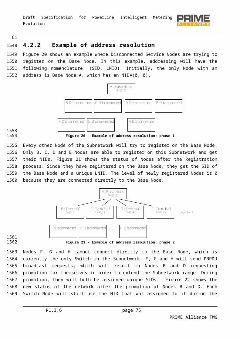
Draft Specification for PowerLine Intelligent Metering Evolution
Uplink Downlink
SID LNID LCID DSID DLNID DLCID NAD
1 1 N 3 1 M 0
3 1 M 1 1 N 1
The direct switching table should be updated every time a Switch receives a control packet that meets the following requirements.
It is CON_REQ_B packet: HDR.DO=1, CON.TYPE=1 and CON.N=0; It contains “direct” information: CON.D=1; The direct information is for itself: CON.DSSID is the SID of the Switch itself.
Then, the direct switching table is updated with the information:
Uplink (SID, LNID, LCID) = (PKT.SID, PKT.LNID, CON.LCID); Downlink (SID, LNID, LCID, NAD) = (CON.DCSID, CON.DCLNID, CON.DCLCID, CON.DCNAD).
The connection closing packets should be used to remove the entries.
The second scenario for using directed connections is when the initiating Service Node already knows the destination Service Node’s EUI-48 address. In this case, rather than using the Base Node’s address, it uses the Service Node’s address. In this case, the Base Node Convergence layer is not involved. The Base Node MAC layer connects Service Node I directly to Service Node F. The resulting Switch table entries are identical to the previous example. The exchange of signals is shown in Figure 30.
R1.3.6 page 75 PRIME Alliance TWG
63
1738
17391740
174117421743
1744
17451746
1747
17481749175017511752
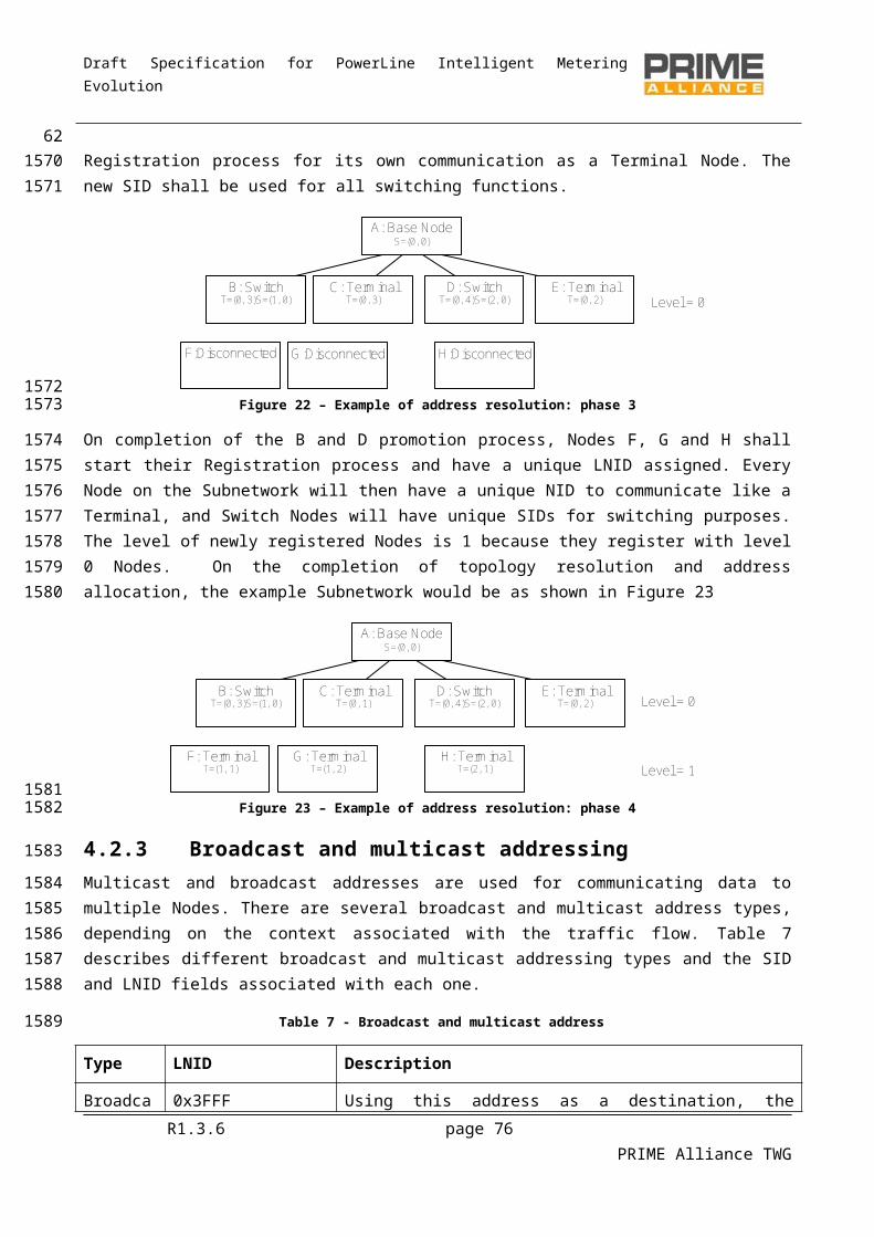
Draft Specification for PowerLine Intelligent Metering Evolution
Figure 30 - Example of direct connection: connection establishment to a known Service Node
4.3.6.2 Direct connection release
The release of a direct connection is shown in Figure 31. The signaling is very similar to connection establishment for a direct connection. The D fields are used to tell the direct Switch which entries it should remove. The direct switching table should be updated every time a Switch receives a control packet that meets the following requirements.
It is CON_CLOSE_B packet: HDR.DO=1, CON.TYPE=1 and CON.N=1; It contains “direct” information: CON.D=1; The direct information is for itself: CON.DSSID is the SID of the Switch itself.
Then, the direct switching table entry with the following information is removed:
Uplink (SID, LNID, LCID) = (PKT.SID, PKT.LNID, CON.LCID); Downlink (SID, LNID, LCID, NAD) = (CON.DCSID, CON.DCLNID, CON.DCLCID, CON.DCNAD).
R1.3.6 page 76 PRIME Alliance TWG
641753
1754
1755
1756
1757175817591760
176117621763
1764
17651766
1767

Draft Specification for PowerLine Intelligent Metering Evolution
Figure 31 - Release of a direct connection
4.3.6.3 Direct connection switching
As explained in section 4.3.5.3, the normal switching mechanism is intended to be used for forwarding communication data between the Base Node and each Service Node. The “direct switching” is a mechanism to let two Nodes communicate with each other, switching the packets in a local way, i.e. without passing through the Base Node. It is not a different form of packet-switching, but rather an additional feature of the general switching process.
The first shared Switch in the paths that go from two Service Nodes to the Base Node will be called the “direct Switch” for the connections between the said Nodes. This is the Switch that will have the possibility of performing the direct switching to make the two Nodes communicate efficiently. As a special case, every Switch is the “direct Switch” between itself and any Node that is lower down in the hierarchy.
The “direct switching table” is a table every Switch should contain in order to perform the direct switching. Each entry on this table is a direct connection that must be switched directly. It is represented by the origin CID and the destination CID of the direct connection. It is not a record of every connection identifier lower down in its hierarchy, but contains only those that should be directly switched by it. The Destination Node’s
R1.3.6 page 77 PRIME Alliance TWG
65
1768
1769
1770
17711772177317741775
1776177717781779
1780
1781178217831784

Draft Specification for PowerLine Intelligent Metering Evolution
ability to receive aggregated packets shall also be included in the “direct switching table” in order to fill the PKT.NAD field.
4.3.6.4 Direct switching operation
If a Switch receives an uplink (HDR.DO=0) MAC frame that is to be switched (see section 4.3.5.3 for the requirements) and its address is in the direct switching table, then the procedure is as follows:
Change the (SID, LNID, LCID, NAD) by the Downlink part of the entry in the direct switching table. Queue the packet to be transmitted as a Downlink packet (HDR.DO=1).
4.3.7 Packet aggregation
4.3.7.1 General
The GPDU may contain one or more packets. The functionality of including multiple packets in a GPDU is called packet aggregation. Packet aggregation is an optional part of this specification and devices do not need to implement it for compliance with this specification. It is however suggested that devices should implement packet aggregation in order to improve MAC efficiency.
To maintain compatibility between devices that implement packet aggregation and ones that do not, there must be a guarantee that no aggregation takes place for packets whose data transit path from/to the Base Node crosses (an) intermediate Service Node(s) that do(es) not implement this function. Information about the aggregation capability of the data transit path is exchanged during the Registration process (4.6.1). A registering Service Node notifies this capability to the Base Node in the REG.CAP_PA field (1 bit, see Table14) of its REG_REQ message. It gets feedback from the Base Node on the aggregation capability of the whole Downlink transit path in the REG.CAP_PA field of the REG_RSP message.
Based on initial information exchanged on Registration, each subsequent data packet in either direction contains aggregation information in the PKT.NAD field. In the Downlink direction, the Base Node will be responsible for filling PKT.NAD based on the value it communicated to the destination Service Node in the REG.CAP_PA field of the REG_RSP message. Likewise, for uplink data, the source Service Node will fill PKT.NAD based on the REG.CAP_PA field received in the initial REG_RSP from the Base Node. The last Switch shall use the PKT.NAD field to avoid packet aggregation when forwarding the packet to destination Service Nodes without packet aggregation capability. Intermediate Switch Nodes should have information about the aggregation capability in their switching table and shall not aggregate packets when it is known that next level Switch Node does not support this feature.
Devices that implement packet aggregation shall ensure that the size of the MSDU comprising the aggregates does not exceed the maximum capacity of the most robust transmission scheme of a PHY burst. The most robust transmission scheme refers to the most robust combination of modulation scheme and convolutional coding.
4.3.7.2 Packet aggregation when switching
Switch Nodes maintain information on the packet aggregation capability of all entries in their switching table, i.e. of all switches that are connected to the Subnetwork through them. This capability information is then used during traffic switching to/from the connected Switch Nodes.
R1.3.6 page 78 PRIME Alliance TWG
6617851786
1787
17881789
17901791
1792
1793
1794179517961797
1798179918001801180218031804
180518061807180818091810181118121813
1814181518161817
1818
181918201821

Draft Specification for PowerLine Intelligent Metering Evolution
The packet aggregation capability of a connecting Switch Node is registered at each transit Switch Node at the time of its promotion by sniffing relevant information in the PRO_ACK message.
If the PKT.SID in a PRO_ACK message is the same as the switching Node, the Node being promoted is connected directly to the said Switch Node. The aggregation capability of this new Switch Node is registered as the same as indicated in PKT.NAD of the PRO_ACK packet.
If the PKT.SID in a PRO_ACK message is different from the SID of the switching Node, it implies that the Node being promoted is indirectly connected to this Switch. The aggregation capability for this new Switch Node will thus be the same as the aggregation capability registered for its immediate Switch, i.e. PKT.SID.
Aggregation while switching packets in uplink direction is performed if the Node performing the Switch knows that its uplink path is capable of handling aggregated packets, based on capability information exchanged during Registration (REG.CAP_PA field in REG_RSP message).
Downlink packets are aggregated by analyzing the following:
If the PKT.SID is the same as the switching Node, then it is the last switching level and the packet will arrive at its destination. In this case, the packet may be aggregated if PKT.NAD=0.
If the PKT.SID is different, this is not the last level and another Switch will receive the packet. The information of whether or not the packet could be aggregated should be extracted from the switching table.
4.3.8 Security
4.3.8.1 General
The security functionality provides the MAC layer with privacy, authentication and data integrity through a secure connection method and a key management policy. All packets must use the negotiated security profile. The only exceptions to this rule are the REG and SEC control messages, and the BPDU and PNPDU PDUs which are transferred non-encrypted.
4.3.8.2 Security Profiles
Several security profiles are provided for managing different security needs, which can arise in different network environments. This version of the specification lists two security profiles and leaves scope for adding up to two new security profiles in future versions.
4.3.8.2.1 Security Profile 0
Communications having Security Profile 0 are based on the transmission of MAC SDUs without encryption. This profile may be used in application scenarios where either sufficient security is provided by upper communication layers or where security is not a major requirement for application use-case.
4.3.8.2.2 Security Profile 1
4.3.8.2.2.1 General
Security Profile 1 is based on 128-bit AES encryption of data and its associated CRC. This profile is specified with the aim of fulfilling all security requirements:
R1.3.6 page 79 PRIME Alliance TWG
6718221823
1824182518261827182818291830
183118321833
1834
18351836183718381839
1840
1841
1842184318441845
1846
184718481849
1850
185118521853
1854
1855
18561857
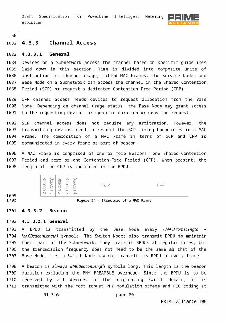
Draft Specification for PowerLine Intelligent Metering Evolution
Privacy is guaranteed by the encryption itself and by the fact that the encryption key is kept secret. Authentication is guaranteed by the fact that each Node has its own secret key known only by the
Node itself and the Base Node. Data integrity is guaranteed by the fact that the payload CRC is encrypted.
4.3.8.2.2.2 Cryptographic primitives
The cryptographic algorithm used in this specification is the AES, as specified in FIPS197. The specification describes the algorithm with three possible key sizes; the 128-bit secret key represents a good level of security for preserving privacy up to 2030 and beyond, as specified in SP800-57, page 66, table 4.
AES is used according to the so-called ECB, as specified in SP800-38A. It is a block-ciphering mode where plain text is divided into 128-bit blocks. Padding is applied if the last block is smaller than 128 bits. Padding is implemented with the addition of a bit equal to 1 and as many zeroes as necessary to reach a length of the string to be encrypted as a multiple of 128 bits. Encryption is performed one block at a time, using the same working key for all the data.
4.3.8.2.2.3 Key Derivation Algorithm
The method for deriving working keys from secret keys is to apply the AES algorithm to a constant (C) as plain text and generation key (GK) as an encryption key. If the constant is shorter than 128 bits, it must be aligned to the LSB, as shown in Figure 32. The various key derivation equations specified in the following subsections follow the convention:
Generated Key = AES_enc (Generation Key, Constant)
Figure 32 - Key derivation concept
4.3.8.3 Negotiation of the Security Profile
All MAC data, including signaling PDUs (all MAC control packets defined in section 4.4.5) use the same security profile. This profile is negotiated during the device Registration. In the REG_REQ message the Terminal indicates a security profile it is able to support in the field REG.SPC. The Base Node may accept this security profile and so accept the Registration, sending back a REG_RSP with the same REG.SPC value. The Base Node may also accept the Registration, however it sets REG.SPC to 0 indicating that security profile 0 is to be used. Alternatively, the Base Node may reject the Registration if the Terminal does not provide an acceptable security profile.
R1.3.6 page 80 PRIME Alliance TWG
681858185918601861
1862
186318641865
18661867186818691870
1871
1872187318741875
1876
18771878
1879
1880188118821883188418851886
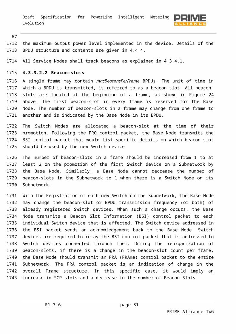
Draft Specification for PowerLine Intelligent Metering Evolution
It is recommended that the Terminal first attempts to register using the highest security profile it supports and only use lower security profiles when the Base Node rejects the Registration request.
4.3.8.4 Key Hierarchy
4.3.8.4.1 Security Profile 0
Not Applicable.
4.3.8.4.2 Security Profile 1
Service Nodes and Base Nodes use a set of three working keys to encrypt all data. The keys and their respective usage are:
Initial Working Key (WK0): This key has limited scope and is used to decrypt the REG.SNK and REG.AUK fields of the REG_RSP message. The WK0 is thus used by a Service Node in a Disconnected functional state. This key is computed using the following formula:
WK0 = AES_enc (USK, 0)
Working Key (WK) : This key is used to encrypt all the unicast data that is transmitted from the Base Node to a Service Node and vice versa. Each registered Service Node would have a unique WK that is known only to the Base Node and itself. The WK is computed as follows:
WK = AES_enc (USK, Random sequence received in SEC.RAN )
Subnetwork Working Key (SWK) : The SWK is shared by the entire Subnetwork. To ensure the security of this key, it is never transmitted over the physical channel, but is computed from other keys which are transmitted encrypted in REG and non-encrypted in SEC control packets. The SWK shall be used to encrypt the following:
Broadcast data, including MAC broadcast control packets. Multicast data. Unicast data that is transacted over direct connections, i.e. not involving the Base Node.
The SWK is computed as follows:
SWK = AES_enc (SNK, Random sequence received in SEC.SNK )
The WK and the SWK have a limited validity time related to the random sequence generation period. The random sequence is regenerated and distributed by the Base Node at least every MACRandSeqChgTime seconds through the SEC control packet. If a device does not receive an update of a random sequence within 2 * MACRandSeqChgTime, it should consider the WK and SWK as no longer valid. Lack of availability of WK will render Service Node to very limited functionality of unregistering from the Subnetwork. It is therefore advised that in such cases, Service Nodes should unregister from the network and initiate a re-registration procedure.
The key derivation procedures have been designed to be indirect and multi-staged to ensure security. The parameters involved in the derivation of the working keys are defined below.
R1.3.6 page 81 PRIME Alliance TWG
6918871888
1889
1890
1891
1892
18931894
189518961897
1898
189919001901
1902
1903190419051906
190719081909
1910
1911
1912191319141915191619171918
19191920

Draft Specification for PowerLine Intelligent Metering Evolution
Master Key (MK1, MK2). Two Master Keys (MK1 and MK2) are defined in this specification. MK1 is used to compute the DSK. MK2 is used to compute the KDIV. Both of these keys are administered on the Base Node by implementation-dependent means that are beyond the scope of this specification. Specifying two master keys makes the USK generation a two stage process, i.e. derivation of DSK and KDIV in the first stage and using them to derive the USK in the second stage. Note that the DSK and KDIV are unique to each registering Service Node.
Device Secret key (DSK). DSK is unique to each Service Node on the Subnetwork and is hard-coded in the device during production. The DSK is constant for the entire life of the Service Node. The Base Node uses MK1 to derive Service Node-specific DSK using the following equation:
DSK = AES_enc (MK1, UI)
Key Diversifier (KDIV). This quantity is also unique to each Service Node, but unlike DSK, it does not have to be a fixed constant for the entire life of the Service Node. The KDIV is provisioned on each Service Node by means that are beyond the scope of this specification. The Base Node computes device-specific KDIV using the equation:
KDIV = AES_enc (MK2, UI)
Unique Secret Key (USK). The USK is used to derive WK0 and WK as defined in the above equations. The USK is in turn computed by applying AES to KDIV, using DSK as the generation key, as shown in the equation below. Note that this is a single-step process in Service Nodes because both KDIV and DSK are already known or provisioned, but a three-step process in the Base Node. The first two steps in the Base Node comprise deriving the DSK and KDIV using the MK1 and MK2, respectively.
USK = AES_enc (DSK, KDIV)
Unique Identifier (UI): The UI of a Service Node shall be its EUI-48.
4.3.8.5 Key distribution and management
The Security Profile for data traffic is negotiated when a device is registered. The REG control packet contains specific fields to indicate Security Profile for respective devices. All connections to/from the device would be required to follow the Security Profile negotiated at the time of Registration. There cannot be a difference in Security Profile across multiple connections involving the same device. The only exception to this would be the Base Node.
The SWK used as a working key for non-unicast traffic and direct connections is never transmitted in non-encrypted form over the physical channel. The SEC broadcast messages transmitted by the Base Node (and relayed by all Switch Nodes) at regular intervals contain random keys for both unicast and non-unicast traffic. When a device initially registers on a Subnetwork, the REG response from the Base Node contains the random sequence used to derive WK for unicast traffic. The REG message is followed by a unicast SEC message from Base Node to the registering device.
R1.3.6 page 82 PRIME Alliance TWG
70192119221923192419251926
192719281929
1930
1931193219331934
1935
19361937193819391940
1941
1942
1943
19441945194619471948
194919501951195219531954
Draft Specification for PowerLine Intelligent Metering Evolution
4.3.8.6 Encryption
4.3.8.6.1 Security Profile 0
Not Applicable.
4.3.8.6.2 Security Profile 1
Connections working with “Security Profile 1” would always transmit a CRC with every packet. This field shall be called SCRC (Security CRC) and is calculated over the unencrypted packet payload. The SCRC helps confirming the integrity of the packet on its decryption at the receiving end.
The SCRC shall be calculated as the remainder of the division (Modulo 2) by the generator polynomial
g(x)=x8+x2+x+1 of the polynomial x8 multiplied by the unencrypted packet payload.
The data block obtained by the concatenation of the unencrypted payload of the packet and the calculated SCRC is padded with a 1 followed by as many zeroes as necessary to reach a multiple of 128 and then divided into 128-bit blocks. The 1 inserted as the first padding bit is useful to detect the start of the padding at the receiver without notification of the number of padded bits.
Each 128-bit block is encrypted with the AES algorithm using a valid working key. The result of this encryption process is the encrypted payload of the packet.
Figure 33 - Security Profile 1 encryption algorithm
4.4 MAC PDU format
4.4.1 GeneralThere are different types of MAC PDUs for different purposes.
4.4.2 Generic MAC PDU
4.4.2.1 General
Most Subnetwork traffic comprises Generic MAC PDUs (GPDU). GPDUs are used for all data traffic and most control traffic. All MAC control packets are transmitted as GPDUs.
R1.3.6 page 83 PRIME Alliance TWG
711955
1956
1957
1958
195919601961
1962
1963
1964196519661967
19681969
19701971
1972
1973
1974
1975
1976
19771978

Draft Specification for PowerLine Intelligent Metering Evolution
GPDU composition is shown in Figure 34Figure 34. It is composed of a Generic MAC Header followed by one or more MAC packets and 32 bit CRC appended at the end.
Figure 34 - Generic MAC PDU format
4.4.2.2 Generic MAC Header
The Generic MAC Header format is represented in Table 9. The size of the Generic MAC Header is 3 bytes. Table 9 enumerates each field of a Generic MAC Header.
Figure 35 - Generic MAC header
Table 9 - Generic MAC header fields
Name Length Description
Unused 2 bits Unused bits which are always 0; included for alignment with MAC_H field in PPDU header (Section 3.4.3).
HDR.HT 2 bits Header Type.
HDR.HT = 0 for GPDU
Reserved 5 bits Always 0 for this version of the specification. Reserved for future use.
HDR.DO 1 bit Downlink/Uplink.
HDR.DO=1 if the MAC PDU is Downlink.
HDR.DO=0 if the MAC PDU is uplink.
HDR.LEVEL 6 bits Level of the PDU in switching hierarchy.
The packets between the level 0 and the Base Node are of HDR.LEVEL=0. The packets between levels k and k-1 are of HDR.LEVEL=k.
If HDR.DO=0, HDR.LEVEL represents the level of the transmitter of this packet.
If HDR.DO=1, HDR.LEVEL represents the level of the receiver of this packet.
R1.3.6 page 84 PRIME Alliance TWG
7219791980
19811982
1983
19841985
19861987
1988
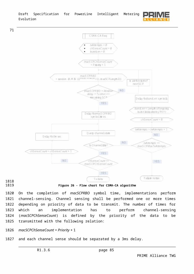
Draft Specification for PowerLine Intelligent Metering Evolution
Name Length Description
HDR.HCS 8 bits Header Check Sequence.
A field for detecting errors in the header and checking that this MAC PDU is from this Subnetwork. The transmitter shall calculate the CRC of the SNA concatenated with the first 2 bytes of the header and insert the result into the HDR.HCS field (the last byte of the header). The CRC shall be calculated as the remainder of the division (Modulo 2) of the polynomial M(x)·x8 by the generator polynomial g(x)=x8+x2+x+1. M(x) is the input polynomial, which is formed by the bit sequence of the concatenation of the SNA and the header excluding the HDR.HCS field, and the msb of the bit sequence is the coefficient of the highest order of M(x).
4.4.2.3 Packet structure
A packet is comprised of a Packet Header and Packet Payload. Figure 36 shows the structure.
Figure 36 - Packet structure
Packet header is 6 bytes in length and its composition is shown in Figure 37. Table 10 enumerates the description of each field.
Figure 37 – Packet Header
To simplify, the text contains references to the PKT.NID fields as the composition of the PKT.SID and PKT.LNID. The field PKT.CID is also described as the composition of the PKT.NID and the PKT.LCID. The composition of these fields is described in Figure 38.
Figure 38 - PKT.CID structure
Table 10 – Packet header fields
Name Length Description
Reserved 3 bits Always 0 for this version of the specification. Reserved for future use.
R1.3.6 page 85 PRIME Alliance TWG
73
1989
1990
19911992
19931994
19951996
199719981999
20002001
20022003
Draft Specification for PowerLine Intelligent Metering Evolution
Name Length Description
PKT.NAD 1 bit No Aggregation at Destination
If PKT.NAD=0 the packet may be aggregated with other packets at destination.
If PKT.NAD=1 the packet may not be aggregated with other packets at destination.
PKT.PRIO 2 bits Indicates packet priority between 0 and 3.
PKT.C 1 bits Control
If PKT.C=0 it is a data packet. If PKT.C=1 it is a control packet.
PKT.LCID /
PKT.CTYPE
9 bits Local Connection Identifier or Control Type
If PKT.C=0, PKT.LCID represents the Local Connection Identifier of data packet. If PKT.C=1, PKT.CTYPE represents the type of the control packet.
PKT.SID 8 bits Switch identifier
If HDR.DO=0, PKT.SID represents the SID of the packet source. If HDR.DO=1, PKT.SID represents the SID of the packet destination.
PKT.LNID 14 bits Local Node identifier.
If HDR.DO=0, PKT.LNID represents the LNID of the packet source If HDR.DO=1, PKT.LNID represents the LNID of the packet destination.
PKT.SPAD 1bit Indicates if padding is inserted while encrypting payload. Note that this bit is only of relevance when Security Profile 1 (see 4.3.8.2.2) is used.
PKT.LEN 9 bits Length of the packet payload in bytes.
4.4.2.4 CRC
The CRC is the last field of the GPDU. It is 32 bits long. It is used to detect transmission errors. The CRC shall cover the concatenation of the SNA with the GPDU except for the CRC field itself.
The input polynomial M(x) is formed as a polynomial whose coefficients are bits of the data being checked (the first bit to check is the highest order coefficient and the last bit to check is the coefficient of order zero). The Generator polynomial for the CRC is G(x)=x32+x26+x23+x22+x16+x12+x11+x10+x8+x7+x5+x4+x2+x+1. The remainder R(x) is calculated as the remainder from the division of M(x)·x32 by G(x). The coefficients of the remainder will then be the resulting CRC.
4.4.3 Promotion Needed PDUIf a Node is Disconnected and it does not have connectivity with any existing Switch Node, it shall send notifications to its neighbors to indicate the need for the promotion of any available Terminal Node. Figure
R1.3.6 page 86 PRIME Alliance TWG
74
2004
20052006
20072008200920102011
2012
20132014
Draft Specification for PowerLine Intelligent Metering Evolution
39 represents the Promotion Needed MAC PDU (PNPDU) that must be sent on an irregular basis in this situation.
Figure 39 - Promotion Need MAC PDU
Table 11 shows the promotion need MAC PDU fields.
Table 11 - Promotion Need MAC PDU fields
Name Length Description
Unused 2 bits Unused bits which are always 0; included for alignment with MAC_H field in PPDU header (Section 3.3.3).
HDR.HT 2 bits Header Type
HDR.HT = 1 for the Promotion Need MAC PDU
Reserved 4 bits Always 0 for this version of the specification. Reserved for future use.
PNH.SNA 48 bits Subnetwork Address.
The EUI-48 of the Base Node of the Subnetwork the Service Node is trying to connect to. FF:FF:FF:FF:FF:FF to ask for the promotion in any available Subnetwork.
SNA[0] is the most significant byte of the OUI/IAB and SNA[5] is the least significant byte of the extension identifier, as defined in:
http://standards.ieee.org/regauth/oui/tutorials/EUI-48.html.
The above notation is applicable to all EUI-48 fields in the specification.
PNH.PNA 48 bits Promotion Need Address. The EUI-48 of the Node that needs the promotion. It is the EUI-48 of the transmitter.
R1.3.6 page 87 PRIME Alliance TWG
7520152016
2017
20182019
2020
2021
Draft Specification for PowerLine Intelligent Metering Evolution
Name Length Description
PNH.HCS 8 bits Header Check Sequence. A field for detecting errors in the header. The transmitter shall calculate the PNH.HCS of the first 13 bytes of the header and insert the result into the PNH.HCS field (the last byte of the header). It shall be calculated as the
remainder of the division (Modulo 2) of the polynomial M(x)·x8 by the generator
polynomial g(x)=x8+x2+x+1. M(x) is the input polynomial, which is formed by the bit sequence of the header excluding the PNH.HCS field, and the msb of the bit sequence is the coefficient of the highest order of M(x).
As it is always transmitted by unsynchronized Nodes and, therefore, prone to creating collisions, it is a special reduced size header. It is broadcast to any other Terminal Node and shall therefore be transmitted with the most robust scheme of the PHY layer.
4.4.4 Beacon PDUBeacon PDU (BPDU) is transmitted by every Switch device on the Subnetwork, including the Base Node. The purpose of this PDU is to circulate information on MAC frame structure and therefore channel access to all devices that are part of this Subnetwork. The BPDU is transmitted at definite fixed intervals of time and is also used as a synchronization mechanism by Service Nodes. Figure 40 below shows contents of a beacon transmitted by the Base Node and each Switch Device.
Figure 40 – Beacon PDU structure
Table 12 shows the beacon PDU fields.Table 12 - Beacon PDU fields
Name Length Description
Unused 2 bits Unused bits which are always 0; included for alignment with MAC_H field in PPDU header (Fig 7, Section 3.3.3).
R1.3.6 page 88 PRIME Alliance TWG
76
2022
202320242025
2026
20272028202920302031
2032
2033
20342035

Draft Specification for PowerLine Intelligent Metering Evolution
Name Length Description
HDR.HT 2 bits Header Type
HDR.HT = 2 for Beacon PDU
Reserved 1 bit Always 0 for this version of the specification. Reserved for future use.
BCN.QLTY 3 bits Quality of round-trip connectivity from this Switch Node to the Base Node. BCN.QLTY=7 for best quality (Base Node or very good Switch Node), BCN.QLTY=0 for worst quality (Switch having unstable connection to Subnetwork)
BCN.SID 8 bits Switch identifier of transmitting Switch
BCN.CNT 3 bits Number of beacon-slots in this frame
BCN.SLT 3 bits Beacon-slot in which this BPDU is transmitted
BCN.SLT=0 is reserved for the Base Node
BCN.CFP 10 bits Offset of CFP from start of frame
BCN.CFP=0 indicates absence of CFP in a frame.
Reserved 1 bit Always 0 for this version of the specification. Reserved for future use.
BCN.LEVEL 6 bits Hierarchy of transmitting Switch in Subnetwork
BCN.SEQ 5 bits Sequence number of this BPDU in super frame. Incremented for every beacon the Base Node sends and is propagated by Switch through its BPDU such that entire Subnetwork has the same notion of sequence number at a given time.
BCN.FRQ 3 bits Transmission frequency of this BPDU. Values are interpreted as follows:
0 = 1 beacon every frame1 = 1 beacon every 2 frames2 = 1 beacon every 4 frames3 = 1 beacon every 8 frames4 = 1 beacon every 16 frames5 = 1 beacon every 32 frames6 = Reserved7 = Reserved
BCN.SNA 48 bits Subnetwork identifier in which the Switch transmitting this BPDU is located
R1.3.6 page 89 PRIME Alliance TWG
77
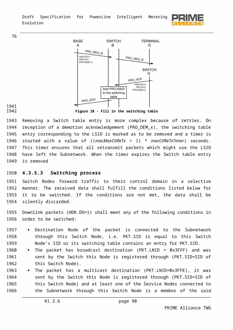
Draft Specification for PowerLine Intelligent Metering Evolution
Name Length Description
BCN.UPCOST 8 bits Total uplink cost from the transmitting Switch Node to the Base Node. The cost of a single hop is calculated based on modulation scheme used on that hop in uplink direction. Values are derived as follows:
8PSK = 0QPSK = 1BPSK = 28PSK_F = 1QPSK_F = 2BPSK_F = 4
The Base Node will transmit in its beacon a BCN.UPCOST of 0. A Switch Node will transmit in its beacon the value of BCN.UPCOST received from its upstream Switch Node, plus the cost of the upstream uplink hop to its upstream Switch. When this value is larger than what can be held in BCN.UPCOST the maximum value of BCN.UPCOST should be used.
BCN.DNCOST 8 bits Total Downlink cost from the Base Node to the transmitting Switch Node. The cost of a single hop is calculated based on modulation scheme used on that hop in Downlink direction. Values are derived as follows:
8PSK 0QPSK 1BPSK 28PSK_F 1QPSK_F 2BPSK_F 4
The Base Node will transmit in its beacon a BCN.DNCOST of 0. A Switch Node will transmit in its beacon the value of BCN.DNCOST received from its upstream Switch Node, plus the cost of the upstream Downlink hop from its upstream Switch. When this value is larger than what can be held in BCN.DNCOST the maximum value of BCN.DNCOST should be used.
CRC 32 bits The CRC shall be calculated with the same algorithm as the one defined for the CRC field of the MAC PDU (see section 4.4.2.4 for details). This CRC shall be calculated over the complete BPDU except for the CRC field itself.
The BPDU is also used to detect when the uplink Switch is no longer available either by a change in the characteristics of the medium or because of failure etc. If a Service Node fails to receive N miss-beacon in a row it should declare the link to its Switch as unusable. The Service Node should stop sending beacons itself if it is acting as a Switch. It should close all existing MAC connections. The Service Node then enters the initial unregistered functional state and searches for a Subnetwork join. This mechanism complements the Keep-Alive mechanism which is used by a Base Node and its switches to determine when a Service Node is lost. R1.3.6 page 90 PRIME Alliance TWG
78
2036
203720382039204020412042
Draft Specification for PowerLine Intelligent Metering Evolution
4.4.5 MAC control packets
4.4.5.1 General
MAC control packets enable a Service Node to communicate control information with their Switch Node, Base Node and vice versa. A control packet is transmitted as a GPDU and is identified with PKT.C bit set to 1 (See section 4.4.2 for more information about the fields of the packets).
There are several types of control messages. Each control message type is identified by the field PKT.CTYPE. Table 13 lists the types of control messages. The packet payload (see section 4.4.2.3) shall contain the information carried by the control packets. This information differs depending on the packet type.
Table 13 - MAC control packet types
Type (PKT.CTYPE) Packet name Packet description
1 REG Registration management
2 CON Connection management
3 PRO Promotion management
4 BSI Beacon Slot Indication
5 FRA Frame structure change
6 CFP Contention-Free Period request
7 ALV Keep-Alive
8 MUL Multicast Management
9 PRM PHY Robustness Management
10 SEC Security information
4.4.5.2 Control packet retransmission
For recovery from lost control messages, a retransmit scheme is defined. MAC control transactions comprising of exchange of more than one control packet may follow the retransmission mechanism described in this section.
The retransmission scheme shall be applied to the following packets when they require a response:
CON_REQ_S, CON_REQ_B; CON_CLS_S, CON_CLS_B; REG_RSP; PRO_REQ_B; BSI_IND; MUL_JOIN_S, MUL_JOIN_B; MUL_LEAVE_S, MUL_LEAVE_B;
R1.3.6 page 91 PRIME Alliance TWG
79
2043
2044
204520462047
204820492050
2051
2052
2053
205420552056
2057
2058205920602061206220632064
Draft Specification for PowerLine Intelligent Metering Evolution
Devices involved in a MAC control transaction using retransmission mechanism shall keep count of number of times a message has been retransmitted and maintain a retransmit timer.
At the requester of a control message transaction:
When the first message in a transaction is transmitted, the retransmit timer is started with value macCtlReTxTimer and the retransmit count is set to 0.
If a response message is received the retransmit timer is stopped and the transaction is considered complete. Note that it is possible to receive further response messages. These would be messages that encountered network delays.
If the retransmit timer expires, the retransmit counter is incremented. If the retransmit counter is less than macMaxCtlReTx the control message is retransmitted. If the counter is equal to the maximum number of retransmits, failure result corresponding to respective MAC-SAP should be returned to the calling entity. Implementations may also choose to inform their local management entity of such failure. If the retransmission is done by the Service Node, the device should return to the disconnected state.
At the responder of a control message transaction:
The receiver of a message must determine itself if this message is a retransmit. If so, no local action is needed other than sending a reply to the response.
If the received message is not a retransmit, the message should be processed and a response returned to the sender.
For transactions which use three messages in the transaction, e.g. promotion as shown in 4.6.3, the responder should perform retransmits in exactly the same way as the requester. This ensures that if the third message in the transaction is lost, the message will be retried and the transaction completed.
The following message sequence charts show some examples of retransmission. Figure 41 shows two successful transactions without requiring retransmits.
R1.3.6 page 92 PRIME Alliance TWG
8020652066
2067
20682069
207020712072
207320742075207620772078
2079
20802081
20822083
2084208520862087
20882089
Draft Specification for PowerLine Intelligent Metering Evolution
Figure 41 – Two transactions without requiring retransmits
Figure 42 shows a more complex example, where messages are lost in both directions causing multiple retransmits before the transaction completes.
Figure 42 - Transaction with packet loss requiring retransmits
Figure 43 shows the case of a delayed response causing duplication at the initiator of the control transaction.
R1.3.6 page 93 PRIME Alliance TWG
81
20902091
20922093
20942095
20962097
Draft Specification for PowerLine Intelligent Metering Evolution
Figure 43 – Duplicate packet detection and elimination
4.4.5.3 REG control packet (PKT.CTYPE=1)
This control packet is used to negotiate the Registration process. The description of data fields of this control packet is described in Table 14 and Figure 44. The meaning of the packets differs depending on the direction of the packet. This packet interpretation is explained in Table 15. These packets are used during the registration and unregistration processes, as explained in 4.6.1 and 4.6.2.
The PKT.SID field is used in this control packet as the Switch where the Service Node is registering. The PKT.LNID field is used in this control packet as the Local Node Identifier being assigned to the Service Node during the registration process negotiation.
The REG.CAP_PA field is used to indicate the packet aggregation capability as discussed in Section 4.3.7. In the uplink direction, this field is an indication from the registering Terminal Node about its own capabilities. For the Downlink response, the Base Node evaluates whether or not all the devices in the cascaded chain from itself to this Terminal Node have packet-aggregation capability. If they do, the Base Node shall set REG.CAP_PA=1; otherwise REG.CAP_PA=0.
R1.3.6 page 94 PRIME Alliance TWG
82
20982099
2100
2101210221032104
210521062107
21082109211021112112
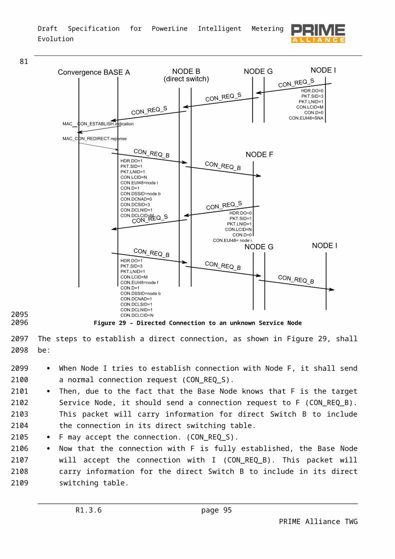
Draft Specification for PowerLine Intelligent Metering Evolution
Figure 44 - REG control packet structure
Table 14 - REG control packet fields
Name Length Description
REG.N 1 bit Negative
REG.N=1 for the negative register; REG.N=0 for the positive register.
(see Table 15)
REG.R 1 bit Roaming
REG.R=1 if Node already registered and wants to perform roaming to another Switch;
REG.R=0 if Node not yet registered and wants to perform a clear registration process.
R1.3.6 page 95 PRIME Alliance TWG
83
2113
2114
2115
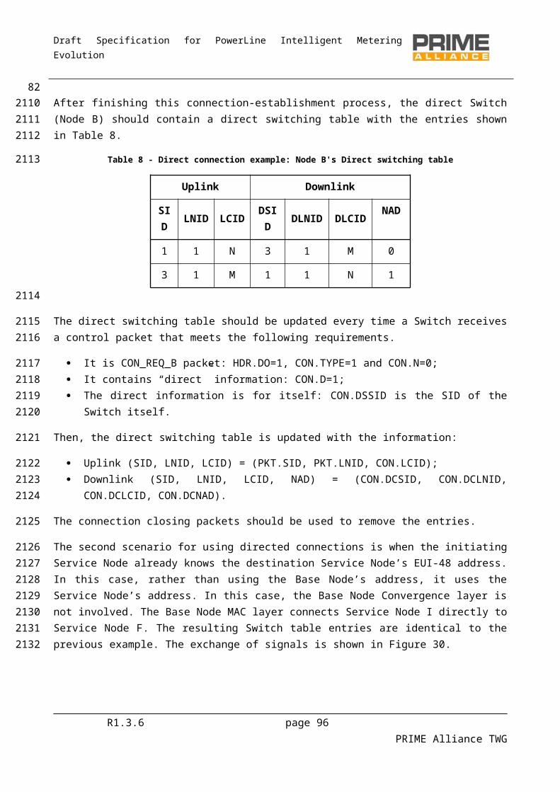
Draft Specification for PowerLine Intelligent Metering Evolution
Name Length Description
REG.SPC 2 bits Security Profile Capability for Data PDUs:
REG.SPC=0 No encryption capability; REG.SPC=1 Security profile 1 capable device; REG.SPC=2 Security profile 2 capable device (not yet specified); REG.SPC=3 Security profile 3 capable device (not yet specified).
Reserved 2 bits Reserved for future versions of the protocol. Should be set to 0 for this version of the protocol.
REG.CAP_SW 1 bit Switch Capable
1 if the device is able to behave as a Switch Node;0 if the device is not.
REG.CAP_PA 1 bit Packet Aggregation Capability
1 if the device has packet aggregation capability (uplink) if the data transit path to the device has packet aggregation capability (Downlink)0 otherwise.
REG.CAP_CFP 1 bit Contention Free Period Capability
1 if the device is able to perform the negotiation of the CFP;0 if the device cannot use the Contention Free Period in a negotiated way.
REG.CAP_DC 1 bit Direct Connection Capability
1 if the device is able to perform direct connections;0 if the device is not able to perform direct connections.
REG.CAP_MC 1 bit Multicast Capability
1 if the device is able to use multicast for its own communications;0 if the device is not able to use multicast for its own communications.
REG.CAP_PRM 1 bit PHY Robustness Management Capable
1 if the device is able to perform PHY Robustness Management;0 if the device is not able to perform PHY Robustness Management.
REG.CAP_ARQ 1 bit ARQ Capable
1 if the device is able to establish ARQ connections;0 if the device is not able to establish ARQ connections.
R1.3.6 page 96 PRIME Alliance TWG
84
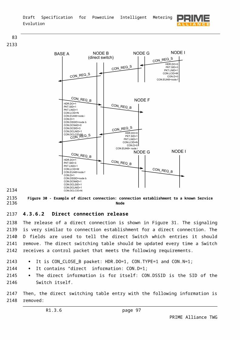
Draft Specification for PowerLine Intelligent Metering Evolution
Name Length Description
REG.TIME 3 bits Time to wait for an ALV_B messages before assuming the Service Node has been unregistered by the Base Node. For all messages except REG_RSP this field should be set to 0. For REG_RSP its value means:
ALV.TIME = 0 => 32 seconds;ALV.TIME = 1 => 64 seconds;ALV.TIME = 2 => 128 seconds ~ 2.1 minutes;ALV.TIME = 3 => 256 seconds ~ 4.2 minutes;ALV.TIME = 4 => 512 seconds ~ 8.5 minutes;ALV.TIME = 5 => 1024 seconds ~ 17.1 minutes;ALV.TIME = 6 => 2048 seconds ~ 34.1 minutes;ALV.TIME = 7 => 4096 seconds ~ 68.3 minutes.
REG.EUI-48 48 bit EUI-48 of the Node
EUI-48 of the Node requesting the Registration.
REG.SNK 128 bits Encrypted Subnetwork key that shall be used to derive the Subnetwork working key
REG.AUK 128 bits Encrypted authentication key. This is a random sequence meant to act as authentication mechanism.
Table 15 - REG control packet types
Name HDR.DO PKT.LNID REG.N REG.R Description
REG_REQ 0 0x3FFF 0 R
Registration request
If R=0 any previous connection from this Node should be lost;
If R=1 any previous connection from this Node should be maintained.
REG_RSP 1 < 0x3FFF 0 RRegistration response. This packet assigns the PCK.LNID to the Service Node.
REG_ACK 0 < 0x3FFF 0 R Registration acknowledged by the Service Node.
REG_REJ 1 0x3FFF 1 0 Registration rejected by the Base Node.
REG_UNR_S 0 < 0x3FFF 1 0
After a REG_UNR_B: Unregistration acknowledge;
Alone: Unregistration request initiated by the Node.
R1.3.6 page 97 PRIME Alliance TWG
85
2116

Draft Specification for PowerLine Intelligent Metering Evolution
Name HDR.DO PKT.LNID REG.N REG.R Description
REG_UNR_B 1 < 0x3FFF 1 0
After a REG_UNR_S: Unregistration acknowledge;
Alone: Unregistration request initiated by the Base Node
Fields REG.SNK and REG.AUK are of significance only for REG_RSP and REG_ACK messages with Security Profile 1 (REG.SCP=1). For all other message-exchange variants using the REG control packet, these fields shall not be present reducing the length of payload.
In REG_RSP message, the REG.SNK and REG.AUK shall always be inserted encrypted with WK0.
In the REG_ACK message, the REG.SNK field shall be set to zero. The contents of the REG.AUK field shall be derived by decrypting the received REG_RSP message with WK0 and re-encrypting the decrypted REG.AUK field with SWK derived from the decrypted REG.SNK and random sequence previously received in SEC control packets.
4.4.5.4 CON control packet (PKT.CTYPE = 2)
This control packet is used for negotiating the connections. The description of the fields of this packet is given in Table 16 and Figure 45 The meaning of the packet differs depending on the direction of the packet and on the values of the different types. Table 17 shows the different interpretation of the packets. The packets are used during the connection establishment and closing. These processes are explained in more detail in 4.6.6.
Figure 45 - CON control packet structure
Note that Figure 45 shows the complete message with all optional parts. When CON.D is 0, CON.DCNAD, CON.DSSID, CON.DCLNID, CON.DCLID, CON.DCSID and the reserved field between CON.DCNAD and CON.DSSID will not be present in the message. Thus, the message will be 6 octets smaller. Similarly, when CON.E is zero, the field CON.EUI-48 will not be present, making the message 6 octets smaller.
Table 16 - CON control packet fields
R1.3.6 page 98 PRIME Alliance TWG
86
2117
211821192120
2121
2122212321242125
2126
21272128212921302131
21322133
2134213521362137
2138

Draft Specification for PowerLine Intelligent Metering Evolution
Name Length Description
CON.N 1 bit Negative
CON.N=1 for the negative connection; CON.N=0 for the positive connection.
CON.D 1 bit Direct connection
CON.D=1 if information about direct connection is carried by this packet;
CON.D=0 if information about direct connection is not carried by this packet.
CON.ARQ 1 bit ARQ mechanism enable
CON.ARQ=1 if ARQ mechanism is enabled for this connection;
CON.ARQ=0 if ARQ mechanism is not enabled for this connection.
CON.E 1 bit EUI-48 presence
CON.E = 1 to have a CON.EUI-48; CON.E = 0 to not have a CON.EUI-48 so that this connection
establishment is for reaching the Base Node CL.
Reserved 3 bits Reserved for future version of the protocol.
This shall be 0 for this version of the protocol.
CON.LCID 9 bits Local Connection Identifier.
The LCID is reserved in the connection request. LCIDs from 0 to 255 are assigned by the connection requests initiated by the Base Node. LCIDs from 256 to 511 are assigned by the connection requests initiated by the local Node.
This is the identifier of the connection being managed with this packet. This is not the same as the PKT.LCID of the generic header, which does not exist for control packets.
CON.EUI-48 48 bits
(Present if CON.E=1)
EUI-48 of destination/source Service Node/Base Node for connection request.
When not performing a directed connection, this field should not be included. When performing a directed connection, it may contain the SNA, indicating that the Base Node Convergence layer should determine the EUI-48.
CON.D = 0, Destination EUI-48; CON.D = 1, Source EUI-48.
R1.3.6 page 99 PRIME Alliance TWG
87

Draft Specification for PowerLine Intelligent Metering Evolution
Name Length Description
Reserved 7 bits
(Present if CON.D=1)
Reserved for future version of the protocol.
This shall be 0 for this version of the protocol.
CON.DCLCID 9 bits
(Present if CON.D=1)
Direct Connection LCID
This field represents the LCID of the connection identifier to which the one being established shall be directly switched.
CON.DCNAD 1 bit
(Present if CON.D=1)
Reserved for future version of the protocol. Direct Connection Not Aggregated at Destination
This field represents the content of the PKT.NAD field after a direct connection Switch operation.
Reserved 1 bits
(Present if CON.D=1)
Reserved for future version of the protocol.
This shall be 0 for this version of the protocol.
CON.DCLNID 14 bits
(Present if CON.D=1)
Direct Connection LNID
This field represents the LNID part of the connection identifier to which the one being established shall be directly switched.
CON.DSSID 8 bits
(Present if CON.D=1)
Direct Switch SID
This field represents the SID of the Switch that should learn this direct connection and perform direct switching.
CON.DCSID 8 bits
(Present if CON.D=1)
Direct Connection SID
This field represents the SID part of the connection identifier to which the one being established shall be directly switched.
CON.TYPE 8 bits Connection type.
The connection type (see Annex E) specifies the Convergence layer to be used for this connection. They are treated transparently through the MAC common part sublayer, and are used only to identify which Convergence layer may be used.
CON.DLEN 8 bits Length of CON.DATA field in bytes
CON.DATA (variable) Connection specific parameters.
These connections specific parameters are Convergence layer specific. They should be defined in each Convergence layer to define the parameters that are specific to the connection. These parameters are handled in a transparent way by the common part sublayer.
R1.3.6 page 100 PRIME Alliance TWG
88
Draft Specification for PowerLine Intelligent Metering Evolution
Table 17 - CON control packet types
Name HDR.DO CON.N Description
CON_REQ_S 0 0 Connection establishment request initiated by the Service Node.
CON_REQ_B 1 0
The Base Node will consider that the connection is established with the identifier CON.LCID.
After a CON_REQ_S: Connection accepted; Alone: Connection establishment request.
CON_CLS_S 0 1
The Service Node considers this connection closed:
After a CON_REQ_B: Connection rejected by the Node; After a CON_CLS_B: Connection closing acknowledge; Alone: Connection closing request.
CON_CLS_B 1 1
The Base Node will consider that the connection is no longer established.
After a CON_REQ_S: Connection establishment rejected by the Base Node;
After a CON_CLS_S: Connection closing acknowledge; Alone: Connection closing request.
4.4.5.5 PRO control packet (PKT.CTYPE = 3)
This control packet is used to promote a Service Node from Terminal function to Switch function. The description of the fields of this packet is given in Table 18, Figure 46 and Figure 47 . The meaning of the packet differs depending on the direction of the packet and on the values of the different types. Table 19 shows the different interpretation of the packets. The promotion process is explained in more detail in 4.6.3.
Figure 46 - PRO_REQ_S control packet structure
R1.3.6 page 101 PRIME Alliance TWG
892139
2140
21412142214321442145
2146
2147
2148

Draft Specification for PowerLine Intelligent Metering Evolution
Figure 47 - PRO control packet structure
Note that Figure 46 includes all fields as used by a PRO_REQ_S message. All other messages are much smaller, containing only PRO.N, PRO.RC, PRO.TIME and PRO.NSID as shown in Figure 47.
Table 18 - PRO control packet fields
Name Length Description
PRO.N 1 bit Negative
PRO.N=1 for the negative promotion
PRO.N=0 for the positive promotion
Reserved 1 bit Reserved for future version of this protocol
This shall be 0 for this version of the protocol.
PRO.RQ 3 bits Receive quality of the PNPDU message received from the Service Node requesting the Terminal to promote.
PRO.TIME 3 bits The ALV.TIME which is being used by the terminal which will become a switch. On a reception of this time in a PRO_REQ_B the Service Node should reset the Keep-Alive timer in the same way as receiving an ALV_B.
PRO.NSID 8 bits New Switch Identifier.
This is the assigned Switch identifier of the Node whose promotion is being managed with this packet. This is not the same as the PKT.SID of the packet header, which must be the SID of the Switch this Node is connected to, as a Terminal Node.
PRO.PNA 0 or 48 bits Promotion Need Address, contains the EUI-48 of the Terminal requesting the Service Node promotes to become a Switch.
This field is only included in the PRO_REQ_S message.
PRO.UPCOST 0 or 8 bits Total uplink cost from the Terminal Node to the Base Node. This value is calculated in the same way a Switch Node calculates the value it places into its own Beacon PDU.
This field is only included in the PRO_REQ_S message.
PRO.DNCOST 0 or 8 bits Total Downlink cost from the Base Node to the Terminal Node. This value is calculated in the same way a Switch Node calculates the value it places into its own Beacon PDU.
This field is only included in the PRO_REQ_S message.
Reserved 4 bits Reserved for future versions of the protocol. Should be set to 0 for this version of the protocol.
R1.3.6 page 102 PRIME Alliance TWG
90
21492150
21512152
2153
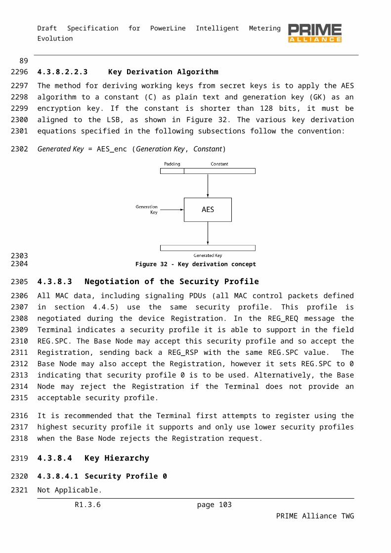
Draft Specification for PowerLine Intelligent Metering Evolution
Name Length Description
PRO.SWC_DC 1 bit Direct Connection Switching Capability
1 if the device is able to behave as Direct Switch in direct connections.
0 otherwise
PRO.SWC_MC 1 bit Multicast Switching Capability
1 if the device is able to manage the multicast traffic when behaving as a Switch.
0 otherwise
PRO.SWC_PRM 1 bit PHY Robustness Management Switching Capability
1 if the device is able to perform PRM for the Terminal Nodes when behaving as a Switch.
0 if the device is not able to perform PRM when behaving as a Switch.
PRO.SWC_ARQ 1 bit ARQ Buffering Switching Capability
1 if the device is able to perform buffering for ARQ connections while switching.
0 if the device is not able to perform buffering for ARQ connections while switching.
Table 19 - PRO control packet types
Name HDR.DO PRO.N PRO.NSID Description
PRO_REQ_S 0 0 0xFF Promotion request initiated by the Service Node.
PRO_REQ_B 1 0 < 0xFF
The Base Node will consider that the Service Node has promoted with the identifier PRO.NSID.
After a PRO_REQ: Promotion accepted; Alone: Promotion request initiated by the Base
Node.
PRO_ACK 0 0 < 0xFF Promotion acknowledge
PRO_REJ 1 1 0xFFThe Base Node will consider that the Service Node is demoted. It is sent after a PRO_REQ to reject it.
PRO_DEM_S 0 1 < 0xFF
The Service Node considers that it is demoted:
After a PRO_DEM_B: Demotion accepted;
After a PRO_REQ_B: Promotion rejected; Alone: Demotion request.
R1.3.6 page 103 PRIME Alliance TWG
91
2154
Draft Specification for PowerLine Intelligent Metering Evolution
Name HDR.DO PRO.N PRO.NSID Description
PRO_DEM_B 1 1 < 0xFF
The Base Node considers that the Service Node is demoted.
After a PRO_DEM_S: Demotion accepted; Alone: Demotion request.
4.4.5.6 BSI control packet (PKT.CTYPE = 4)
The Beacon Slot Information (BSI) control packet is only used by the Base Node and Switch Nodes. It is used to exchange information that is further used by a Switch Node to transmit its beacon. The description of the fields of this packet is given in Table 20 and Figure 48. The meaning of the packet differs depending on the direction of the packet and on the values of the different types. Table 21 represents the different interpretation of the packets. The promotion process is explained in more detail in 4.6.3.
Figure 48 - BSI control packet structure
Table 20 - BSI control packet fields
Name Length Description
Reserved 5 bits Reserved for future version of this protocol. In this version, this field should be initialized to 0.
BSI.FRQ 3 bits Transmission frequency of Beacon Slot, encoded as:
FRQ = 0 => 1 beacon every frame FRQ = 1 => 1 beacon every 2 frames FRQ = 2 => 1 beacon every 4 frames FRQ = 3 => 1 beacon every 8 frames FRQ = 4 => 1 beacon every 16 frames FRQ = 5 => 1 beacon every 32 frames FRQ = 6 => Reserved FRQ = 7 => Reserved
BSI.SLT 3 bits Beacon Slot to be used by target Switch
BSI.SEQ 5 bits The Beacon Sequence number when the specified change takes effect.
Table 21 - BSI control message types
Name HDR.DO Description
BSI_ACK 0 Acknowledgement of receipt of BSI control message
BSI_IND 1 Beacon-slot change command
R1.3.6 page 104 PRIME Alliance TWG
92
2155
21562157215821592160
2161
2162
2163
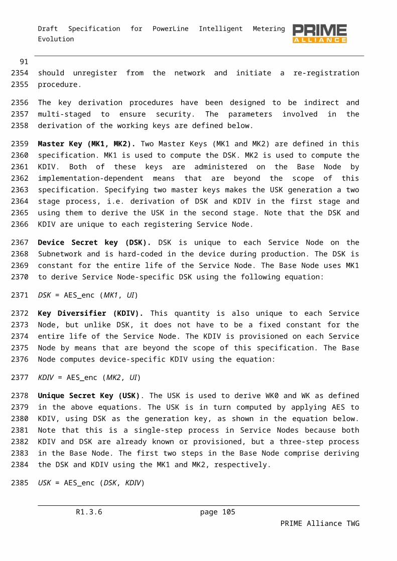
Draft Specification for PowerLine Intelligent Metering Evolution
4.4.5.7 FRA control packet (PKT.CTYPE = 5)
This control packet is broadcast from the Base Node and relayed by all Switch Nodes to the entire Subnetwork. It is used to circulate information on the change of Frame structure at a specific time in future. The description of fields of this packet is given in Table 22 and Figure 49. Table 23 shows the different interpretation of the packets.
Figure 49 - FRA control packet structure
Table 22 - FRA control packet fields
Name Length Description
FRA.TYP 2 bits 0: Beacon count change
1: CFP duration change
Reserved 4 bits Reserved for future version of this protocol. In this version, this field should be initialized to 0.
FRA.CFP 10 bits Offset of CFP from start of frame
FRA.SEQ 5 bits The Beacon Sequence number when the specified change takes effect.
FRA.BCN 3 bits Number of beacons in a frame
Table 23 - FRA control packet types
Name FRA.TYP Description
FRA_BCN_IND 0 Indicates changes to frame structure due to change in beacon-slot count
FRA_CFP_IND 1Indicates changes to frame structure due to change in CFP duration as a result of grant of CFP or end of CFP period for any requesting Service Node in the Subnetwork.
4.4.5.8 CFP control packet (PKT.CTYPE = 6)
This control packet is used for dedicated contention-free channel access time allocation to individual Terminal or Switch Nodes. The description of the fields of this packet is given in Table 24 and Figure 50. The meaning of the packet differs depending on the direction of the packet and on the values of the different types. Table 25 represents the different interpretation of the packets.
R1.3.6 page 105 PRIME Alliance TWG
932164
2165216621672168
21692170
2171
2172
2173
2174217521762177
2178

Draft Specification for PowerLine Intelligent Metering Evolution
Figure 50 - CFP control packet structure
Table 24 - CFP control message fields
Name Length Description
CFP.N 1 bit 0: denial of allocation/deallocation request;1: acceptance of allocation/deallocation request.
CFP.DIR 1 bit Indicate direction of allocation.
0: allocation is applicable to uplink (towards Base Node) direction;1: allocation is applicable to Downlink (towards Service Node) direction.
CFP.SEQ 5 bits The Beacon Sequence number when the specified change takes effect.
CFP.LCID 9 bits LCID of requesting connection.
CFP.LEN 7 bits Length (in symbols) of requested/allocated channel time per frame.
CFP.POS 9 bits Offset (in symbols) of allocated time from beginning of frame.
CFP.TYPE 2 bits 0: Channel allocation packet;
1: Channel de-allocation packet;
2: Channel change packet.
CFP.LNID 14 bits LNID of Service Node that is the intended user of the allocation.
Table 25 - CFP control packet types
Name CFP.TYP HDR.DO Description
CFP_ALC_REQ_S 0 0 Service Node makes channel allocation request
CFP_ALC_IND 0 1 After a CFP_ALC_REQ_S: Requested channel is allocated Alone: Unsolicited channel allocation by Base Node
CFP_ALC_REJ 0 1 Requested channel allocation is denied
CFP_DALC_REQ 1 0 Service Node makes channel de-allocation request
CFP_DALC_RSP 1 1 Base Node confirms de-allocation
CFP_CHG_IND 2 1 Change of location of allocated channel within the CFP.
R1.3.6 page 106 PRIME Alliance TWG
94
21792180
2181
2182
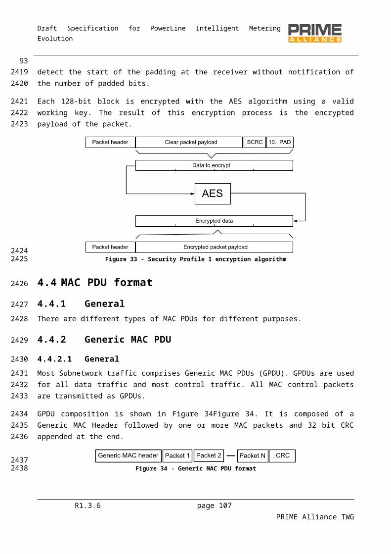
Draft Specification for PowerLine Intelligent Metering Evolution
4.4.5.9 ALV control packet (PKT.CTYPE = 7)
The ALV control message is used for Keep-Alive signaling between a Service Node, the Service Nodes above it and the Base Node. The message exchange is bidirectional, that is, a message is periodically exchanged in each direction. The structure of these messages are shown in Figure 51 and Table 26. The different Keep-Alive message types are shown in Table 27. These messages are sent periodically, as described in section 4.6.5.
Figure 51 - ALV Control packet structure
Table 26 - ALV control message fields
Name Length Description
ALV.RXCNT 3 bits Modulo 8 counter to indicate number of received ALV messages.
ALV.TXCNT 3 bits Modulo 8 counter to indicate number of transmitted ALV messages.
Reserved 7 bits Should always be encoded as 0 in this version of the specification.
ALV.TIME 3 bits Time to wait for an ALV_B messages before assuming the Service Node has been unregistered by the Base Node.
ALV.TIME = 0 => 32 seconds;ALV.TIME = 1 => 64 seconds;ALV.TIME = 2 => 128 seconds ~ 2.1 minutes;ALV.TIME = 3 => 256 seconds ~ 4.2 minutes;ALV.TIME = 4 => 512 seconds ~ 8.5 minutes;ALV.TIME = 5 => 1024 seconds ~ 17.1 minutes;ALV.TIME = 6 => 2048 seconds ~ 34.1 minutes;ALV.TIME = 7 => 4096 seconds ~ 68.3 minutes.
ALV.SSID 8 bits For a Terminal, this should be 0xFF. For a Switch, this is its Switch Identifier.
Table 27 – Keep-Alive control packet types
Name HDR.DO Description
ALV_S 0 Keep-Alive message from a Service Node
ALV_B 1 Keep-Alive message from the Base Node
R1.3.6 page 107 PRIME Alliance TWG
952183
21842185218621872188
2189
21902191
2192
2193
2194
2195
2196
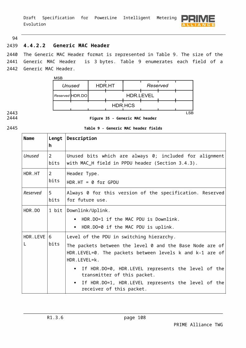
Draft Specification for PowerLine Intelligent Metering Evolution
4.4.5.10 MUL control packet (PKT.CTYPE = 8)
The MUL message is used to control multicast group membership. The structure of this message and the meanings of the fields are described in Table 28 and Figure 52. The message can be used in different ways as described in Table 29.
Figure 52 - MUL control packet structure
Table 28 - MUL control message fields
Name Length Description
MUL.N 1 bit Negative
MUL.N = 1 for the negative multicast connection, i.e. multicast group leave.
MUL.N = 0 for the positive multicast connection, i.e. multicast group join.
Reserved 6 bits Reserved for future version of the protocol.
This shall be 0 for this version of the protocol.
MUL.LCID 9 bits Local Connection Identifier.
The LCID indicates which multicast distribution group is being managed with this message.
MUL.TYPE 8 bits Connection type.
The connection type specifies the Convergence layer to be used for this connection. They are treated transparently through the MAC common part sublayer, and are used only to identify which Convergence layer may be used. See Annex E.
MUL.DLEN 8 bits Length of data in bytes in the MUL.DATA field
MUL.DATA (variable) Connection specific parameters.
These connections specific parameters are Convergence layer specific. They should be defined in each Convergence layer to define the parameters that are specific to the connection. These parameters are handled in a transparent way by the common part sublayer.
R1.3.6 page 108 PRIME Alliance TWG
962197
219821992200
22012202
22032204
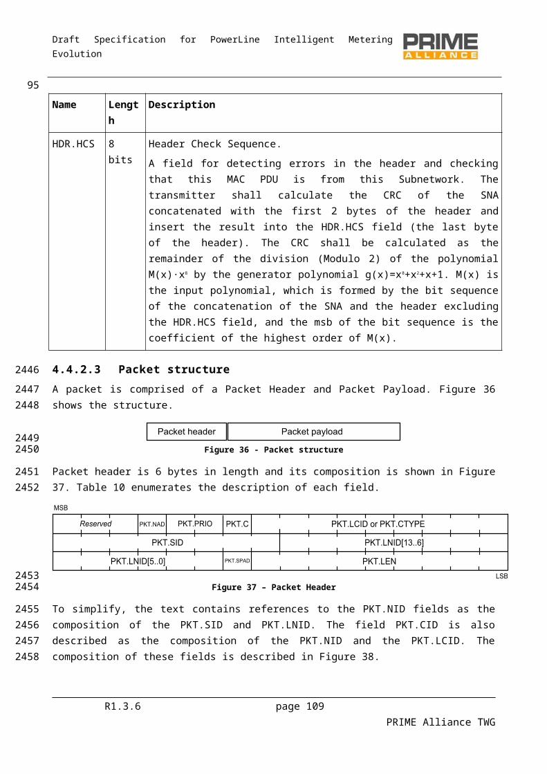
Draft Specification for PowerLine Intelligent Metering Evolution
Table 29 – MUL control message types
Name HDR.DO MUL.N Description
MUL_JOIN_S 0 0Multicast group join request initiated by the Service Node, or an acknowledgement when sent in response to a MUL_JOIN_B.
MUL_JOIN_B 1 0
The Base Node will consider that the group has been joined with the identifier MUL.LCID.
After a MUL_JOIN_S: join accepted;
Alone: group join request.
MUL_LEAVE_S 0 1
The Service Node leaves the multicast group:
After a MUL_JOIN_B: Join rejected by the Node; After a MUL_LEAVE_B: group leave acknowledge;
Alone: group leave request.
MUL_LEAVE_B 1 1
The Base Node will consider that the Service Node is no longer a member of the multicast group.
After a MUL_JOIN_S: Group join rejected by the Base Node;
After a MUL_LEAVE_S: Group leave acknowledge; Alone: Group leave request.
4.4.5.11 PRM control packet (PKT.CTYPE = 9)
The PHY Robustness Management packets are used to control the parameters that affect the robustness and efficiency of the PHY. These packets are sent to notify to the peer of the need to improve robustness of the transmission, or to notify the peer that the reception quality is so good that a less robust and so more efficient modulation scheme can be transmitted.
The fields of the PRM control packet are described in Table 30 and Figure 53 and the types of messages are described in Table 31
Figure 53 – PHY control packet structure
Table 30 – PRM control message fields
Name Length Description
PRM.R 1 bit Response
PRM.R=1 if this message is a response; PRM.R=0 if this message is a request.
R1.3.6 page 109 PRIME Alliance TWG
972205
2206
2207220822092210
22112212
22132214
22152216

Draft Specification for PowerLine Intelligent Metering Evolution
PRM.N 1 bit Negative
PRM.N=1 if the operation could not be performed; PRM.N=0 if the operation was performed.
Reserved 3 bits Should always be encoded as 0 in this version of the specification.
PRM.SNR 3 bits Indicates the SNR at the end that initiates a change request, obtained using PHY_SNR primitive (Section 3.9.3.)
Table 31 – PRM control message types
Name PRM.R PRM.N Description
PRM_REQ 0 0 PHY modulation management request.
PRM_ACK 1 0 PHY modulation management acknowledge.
PRM_REJ 1 1 PHY modulation management rejected.
4.4.5.12 SEC control packet (PKT.CTYPE = 10)
The SEC control message is broadcast unencrypted by the Base Node and all Switch Nodes to the rest of the Subnetwork in order to circulate the random sequence used to generate working keys. The random sequence used by devices in a Subnetwork is dynamic and changes from time to time to ensure a robust security framework. The structure of this message is shown in Table 32and Figure 54. Further details of security mechanisms are given in Section 4.3.8.
R1.3.6 page 110 PRIME Alliance TWG
98
2217
2218
22192220222122222223
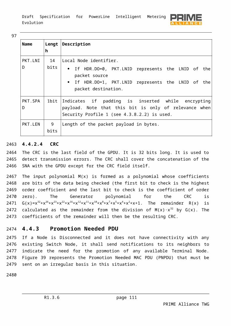
Draft Specification for PowerLine Intelligent Metering Evolution
SEC.SNK
SEC.SNK
SEC.SNK
SEC.SNK
SEC.SNK
SEC.SNKSEC.SNK
SEC.SNK
SEC.SNK
Figure 54 – SEC control packet structure
Table 32 – SEC control message fields
Name Length Description
SEC.RAN 128 bits Random sequence to be used to derive WK.
SEC.SNK 128 bits Random sequence to be used to derive SWK.
Reserved 2 bits Should always be encoded as 0 in this version of the specification.
SEC.USE 1 bits When 1 indicates the random sequences are already in use.
When 0 indicates that SE.SEQ should be used to determine when to start using these random sequences.
SEC.SEQ 5 bits
The Beacon Sequence number when the specified change takes effect.
R1.3.6 page 111 PRIME Alliance TWG
99
22242225
22262227
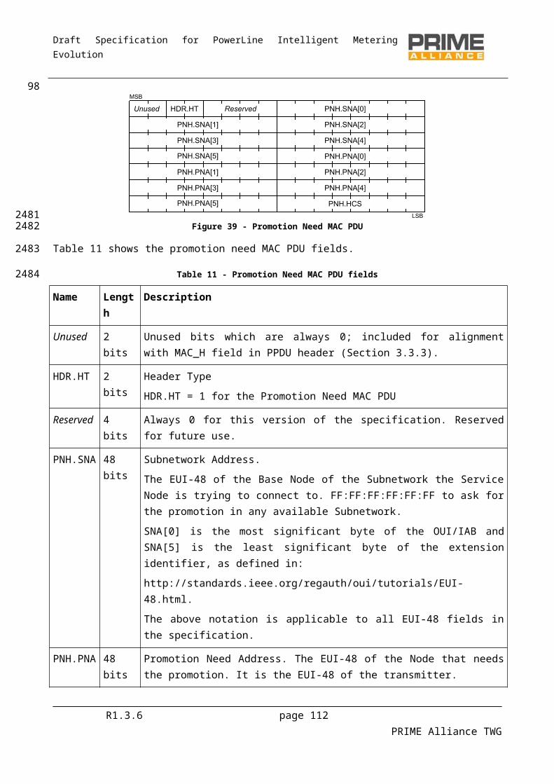
Draft Specification for PowerLine Intelligent Metering Evolution
4.5 MAC Service Access Point
4.5.1 GeneralThe MAC service access point provides several primitives to allow the Convergence layer to interact with the MAC layer. This section aims to explain how the MAC may be used. An implementation of the MAC may not use all the primitives listed here; it may use other primitives; or it may have a function-call based interface rather than message-passing, etc. These are all implementation issues which are beyond the scope of this specification.
The .request primitives are passed from the CL to the MAC to request the initiation of a service. The .indication and .confirm primitives are passed from the MAC to the CL to indicate an internal MAC event that is significant to the CL. This event may be logically related to a remote service request or may be caused by an event internal to the local MAC. The .response primitive is passed from the CL to the MAC to provide a response to a .indication primitive. Thus, the four primitives are used in pairs, the pair .request and .confirm and the pair .indication and .response. This is shown in Figure 55, Figure 56, Figure 57 and Figure 58.
Figure 55 – Establishment of a Connection Figure 56 – Failed establishment of a Connection
Figure 57 – Release of a Connection Figure 58- Transfer of Data
Table 33 represents the list of available primitives in the MAC-SAP:
Table 33 – List of MAC primitives
Service Node primitives Base Node primitives
MAC_ESTABLISH.request MAC_ESTABLISH.request
MAC_ESTABLISH.indication MAC_ESTABLISH.indication
R1.3.6 page 112 PRIME Alliance TWG
100
2228
2229
22302231223222332234
2235223622372238223922402241
2242
2243

Draft Specification for PowerLine Intelligent Metering Evolution
Service Node primitives Base Node primitives
MAC_ESTABLISH.response MAC_ESTABLISH.response
MAC_ESTABLISH.confirm MAC_ESTABLISH.confirm
MAC_RELEASE.request MAC_RELEASE.request
MAC_RELEASE.indication MAC_RELEASE.indication
MAC_RELEASE.response MAC_RELEASE.response
MAC_RELEASE.confirm MAC_RELEASE.confirm
MAC_JOIN.request MAC_JOIN.request
MAC_JOIN.Response MAC_JOIN.response
MAC_JOIN.indication MAC_JOIN.indication
MAC_JOIN.confirm MAC_JOIN.confirm
MAC_LEAVE.request MAC_LEAVE.request
MAC_LEAVE.indication MAC_LEAVE.indication
MAC_LEAVE.confirm MAC_LEAVE.confirm
MAC_DATA.request MAC_REDIRECT.response
MAC_DATA.confirm MAC_DATA.request
MAC_DATA.indication MAC_DATA.confirm
MAC_DATA.indication
4.5.2 Service Node and Base Node signalling primitives
4.5.2.1 General
The following subsections describe primitives which are available in both the Service Node and Base Node MAC-SAP. These are signaling primitives only and used for establishing and releasing MAC connections.
4.5.2.2 MAC_ESTABLISH
4.5.2.2.1 General
The MAC_ESTABLISH primitives are used to manage a connection establishment.
4.5.2.2.2 MAC_ESTABLISH.request
The MAC_ESTABLISH.request primitive is passed to the MAC layer entity to request the connection establishment.
The semantics of this primitive are as follows:
R1.3.6 page 113 PRIME Alliance TWG
101
2244
2245
22462247
2248
2249
2250
2251
22522253
2254
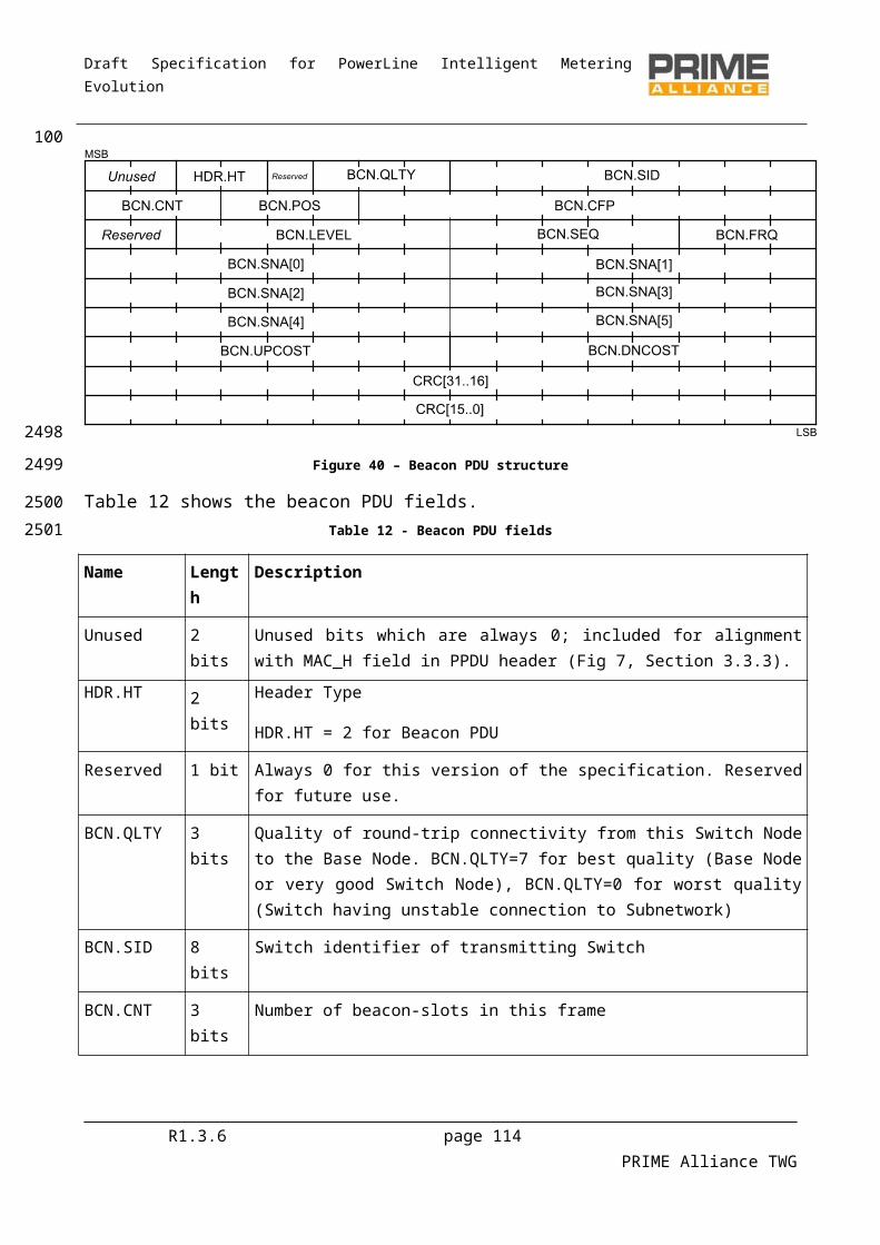
Draft Specification for PowerLine Intelligent Metering Evolution
MAC_ESTABLISH.requestEUI-48, Type, Data, DataLength, ARQ, CfBytes
The EUI-48 parameter of this primitive is used to specify the address of the Node to which this connection will be addressed. The MAC will internally transfer this to an address used by the MAC layer. When the CL of a Service Node wishes to connect to the Base Node, it uses the EUI-48 00:00:00:00:00:00. However, when the CL of a Service Node wishes to connect to another Service Node on the Subnetwork, it uses the EUI-48 of that Service Node. This will then trigger a direct connection establishment. However, whether a normal or a directed connection is established is transparent to the Service Node MAC SAP. As the EUI-48 of the Base Node is the SNA, the connection could also be requested from the Base Node using the SNA.
The Type parameter is an identifier used to define the type of the Convergence layer that should be used for this connection (see Annex E). This parameter is 1 byte long and will be transmitted in the CON.TYPE field of the connection request.
The Data parameter is a general purpose buffer to be interchanged for the negotiation between the local CL and the remote CL. This parameter will be transmitted in the CON.DATA field of the connection request.
The DataLength parameter is the length of the Data parameter in bytes.
The ARQ parameter indicates whether or not the ARQ mechanism should be used for this connection. It is a Boolean type with a value of true indicating that ARQ will be used.
The CfBytes parameter is used to indicate whether or not the connection should use the contention or contention-free channel access scheme. When CfBytes is zero, contention-based access should be used. When CfBytes is not zero, it indicates how many bytes per frame should be allocated to the connection using CFP packets.
4.5.2.2.3 MAC_ESTABLISH.indication
The MAC_ESTABLISH.indication is passed from the MAC layer to indicate that a connection establishment was initiated by a remote Node.
The semantics of this primitive are as follows:
MAC_ESTABLISH.indicationConHandle, EUI-48, Type, Data, DataLength, CfBytes
The ConHandle is a unique identifier interchanged to uniquely identify the connection being indicated. It has a valid meaning only in the MAC SAP, used to have a reference to this connection between different primitives.
The EUI-48 parameter indicates which device on the Subnetwork wishes to establish a connection.
The Type parameter is an identifier used to define the type of the Convergence layer that should be used for this connection. This parameter is 1 byte long and it is received in the CON.TYPE field of the connection request.
The Data parameter is a general purpose buffer to be interchanged for the negotiation between the remote CL and the local CL. This parameter is received in the CON.DATA field of the connection request.
The DataLength parameter is the length of the Data parameter in bytes.
R1.3.6 page 114 PRIME Alliance TWG
1022255
2256225722582259226022612262
226322642265
22662267
2268
22692270
2271227222732274
2275
22762277
2278
2279
228022812282
2283
228422852286
22872288
2289
Draft Specification for PowerLine Intelligent Metering Evolution
The CfBytes parameter is used to indicate if the connection should use the contention or contention-free channel access scheme. When CfBytes is zero, contention-based access will be used. When CfBytes is not zero, it indicates how many bytes per frame the connection would like to be allocated.
4.5.2.2.4 MAC_ESTABLISH.response
The MAC_ESTABLISH.response is passed to the MAC layer to respond with a MAC_ESTABLISH.indication.
The semantics of this primitive are as follows:
MAC_ESTABLISH.responseConHandle, Answer, Data, DataLength
The ConHandle parameter is the same as the one that was received in the MAC_ESTABLISH.indication.
The Answer parameter is used to notify the MAC of the action to be taken for this connection establishment. This parameter may have one of the values in Table 34.
The Data parameter is a general purpose buffer to be interchanged for the negotiation between the remote CL and the local CL. This parameter is received in the CON.DATA field of the connection response.
The DataLength parameter is the length of the Data parameter in bytes.
Data may be passed to the caller even when the connection is rejected, i.e. Answer has the value 1. The data may then optionally contain more information as to why the connection was rejected.
Table 34 – Values of the Answer parameter in MAC_ESTABLISH.response primitive
Answer Description
Accept = 0 The connection establishment is accepted.
Reject = 1 The connection establishment is rejected.
4.5.2.2.5 MAC_ESTABLISH.confirm
The MAC_ESTABLISH.confirm is passed from the MAC layer as the remote answer to a MAC_ESTABLISH.request.
The semantics of this primitive are as follows:
MAC_ESTABLISH.confirmConHandle, Result, EUI-48, Type, Data, DataLength
The ConHandle is a unique identifier to uniquely identify the connection being indicated. It has a valid meaning only in the MAC SAP, used to have a reference to this connection between different primitives. The value is only valid if the Result parameter is 0.
The Result parameter indicates the result of the connection establishment process. It may have one of the values in Table 35 .
The EUI-48 parameter indicates which device on the Subnetwork wishes to establish a connection.
R1.3.6 page 115 PRIME Alliance TWG
103229022912292
2293
2294
2295
2296
2297
22982299
23002301
2302
23032304
2305
2306
23072308
2309
2310
231123122313
23142315
2316
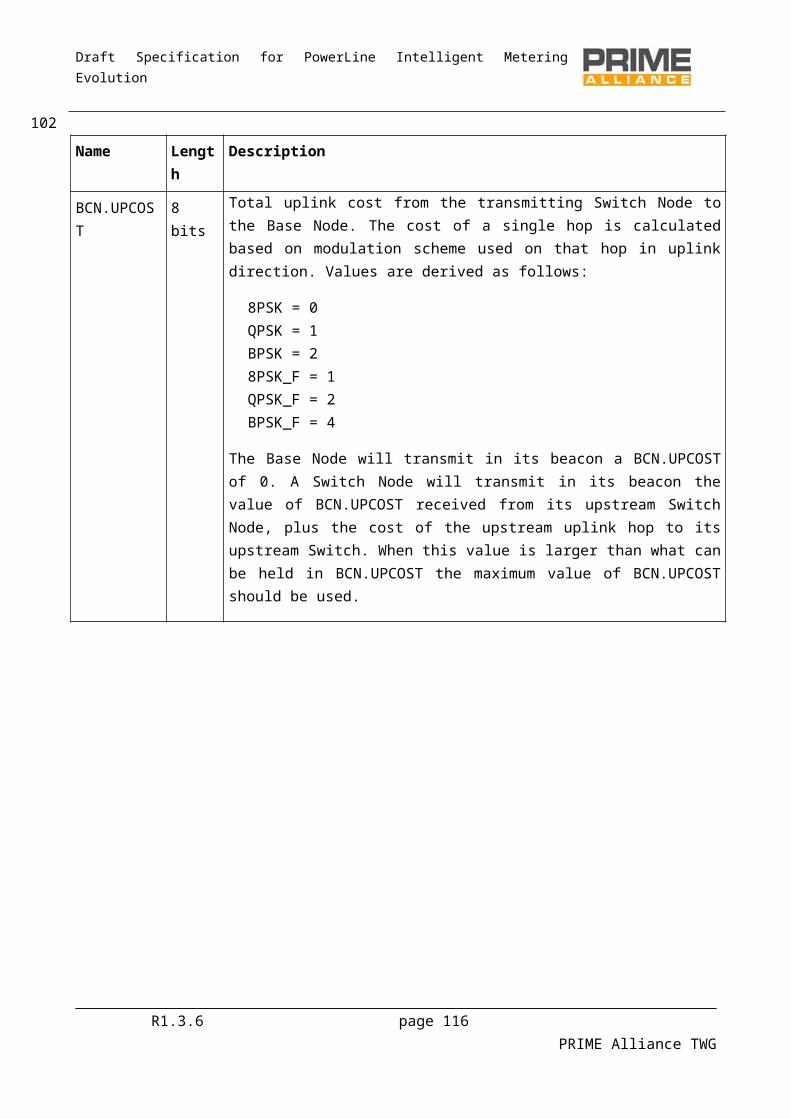
Draft Specification for PowerLine Intelligent Metering Evolution
The Type parameter is an identifier used to define the type of the Convergence layer that should be used for this connection. This parameter is 1 byte long and it is received in the CON.TYPE field of the connection request
The Data parameter is a general purpose buffer to be interchanged for the negotiation between the remote CL and the local CL. This parameter is received in the CON.DATA field of the connection response.
The DataLength parameter is the length of the Data parameter in bytes.
Data may be passed to the caller even when the connection is rejected, i.e. Result has the value 1. The data may then optionally contain more information as to why the connection was rejected.
Table 35 – Values of the Result parameter in MAC_ESTABLISH.confirm primitive
Result Description
Success = 0 The connection establishment was successful.
Reject = 1 The connection establishment failed because it was rejected by the remote Node.
Timeout = 2 The connection establishment process timed out.
No bandwidth = 3 There is insufficient available bandwidth to accept this contention-free connection.
No Such Device = 4 A device with the destination address cannot be found.
Redirect failed =5 The Base Node attempted to perform a redirect which failed.
Not Registered = 6 The Service Node is not registered.
No More LCIDs = 7 All available LCIDs have been allocated.
4.5.2.3 MAC_RELEASE
4.5.2.3.1 General
The MAC_RELEASE primitives are used to release a connection.
4.5.2.3.2 MAC_RELEASE.request
The MAC_RELEASE.request is a primitive used to initiate the release process of a connection.
The semantics of this primitive are as follows:
MAC_RELEASE.requestConHandle
The ConHandle parameter specifies the connection to be released. This handle is the one that was obtained during the MAC_ESTABLISH primitives.
4.5.2.3.3 MAC_RELEASE.indication
The MAC_RELEASE.indication is a primitive used to indicate that a connection is being released. It may be released because of a remote operation or because of a connectivity problem.
R1.3.6 page 116 PRIME Alliance TWG
104231723182319
23202321
2322
23232324
2325
2326
2327
2328
2329
2330
2331
2332
23332334
2335
23362337

Draft Specification for PowerLine Intelligent Metering Evolution
The semantics of this primitive are as follows:
MAC_RELEASE.indicationConHandle, Reason
The ConHandle parameter specifies the connection being released. This handle is the one that was obtained during the MAC_ESTABLISH primitives.
The Reason parameter may have one of the values given in Table 36.
Table 36 – Values of the Reason parameter in MAC_RELEASE.indication primitive
Reason Description
Success = 0 The connection release was initiated by a remote service.
Error = 1 The connection was released because of a connectivity problem.
4.5.2.3.4 MAC_RELEASE.response
The MAC_RELEASE.response is a primitive used to respond to a connection release process.
The semantics of this primitive are as follows:
MAC_RELEASE.responseConHandle, Answer
The ConHandle parameter specifies the connection being released. This handle is the one that was obtained during the MAC_ESTABLISH primitives.
The Answer parameter may have one of the values given in Table 37 This parameter may not have the value “Reject = 1” because a connection release process cannot be rejected.
Table 37 – Values of the Answer parameter in MAC_RELEASE.response primitive
Answer Description
Accept = 0 The connection release is accepted.
After sending the MAC_RELEASE.response the ConHandle is no longer valid and should not be used.
4.5.2.3.5 MAC_RELEASE.confirm
The MAC_RELEASE.confirm primitive is used to confirm that the connection release process has finished.
The semantics of this primitive are as follows:
MAC_RELEASE.confirmConHandle, Result
The ConHandle parameter specifies the connection released. This handle is the one that was obtained during the MAC_ESTABLISH primitives.
The Result parameter may have one of the values given in Table 38
R1.3.6 page 117 PRIME Alliance TWG
1052338
2339
23402341
2342
2343
2344
2345
2346
2347
23482349
23502351
2352
2353
2354
2355
2356
2357
2358
23592360
2361
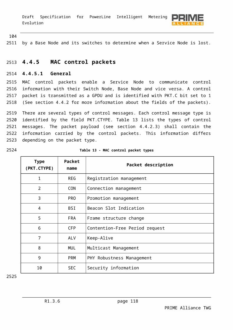
Draft Specification for PowerLine Intelligent Metering Evolution
Table 38 – Values of the Result parameter in MAC_RELEASE.confirm primitive
Result Description
Success = 0 The connection release was successful.
Timeout = 2 The connection release process timed out.
Not Registered = 6 The Service Node is no longer registered.
After the reception of the MAC_RELEASE.confirm the ConHandle is no longer valid and should not be used.
4.5.2.4 MAC_JOIN
4.5.2.4.1 General
The MAC_JOIN primitives are used to join to a broadcast or multicast connection and allow the reception of such packets.
4.5.2.4.2 MAC_JOIN.request
The MAC_JOIN.request primitive is used:
By all Nodes : to join broadcast traffic of a specific CL and start receiving these packets By Service Nodes : to join a particular multicast group By Base Node : to invite a Service Node to join a particular multicast group
Depending on which device makes the join-request, this SAP can have two different variants. First variant shall be used on Base Nodes and second on Service Nodes:
The semantics of this primitive are as follows:
MAC_JOIN.requestBroadcast, ConHandle, EUI-48, Type, Data, DataLength
MAC_JOIN.request(Broadcast, Type, Data, Datalength
The Broadcast parameter specifies whether the JOIN operation is being performed for a broadcast connection or for a multicast operation. It should be 1 for a broadcast operation and 0 for a multicast operation. In case of broadcast operation, EUI-48, Data, DataLength are not used.
ConHandle indicates the handle to be used with for this multicast join. In case of first join request for a new multicast group, ConHandle will be set to 0. For any subsequent EUI additions to an existing multicast group, ConHandle will serve as index to respective multicast group.
The EUI-48 parameter is used by the Base Node to specify the address of the Node to which this join request will be addressed. The MAC will internally transfer this to an address used by the MAC layer. When the CL of a Service Node initiates the request, it uses the EUI-48 00:00:00:00:00:00.
The Type parameter defines the type of the Convergence layer that will send/receive the data packets. This parameter is 1 byte long and will be transmitted in the MUL.TYPE field of the join request.
R1.3.6 page 118 PRIME Alliance TWG
1062362
2363
2364
2365
2366
23672368
2369
2370
237123722373
23742375
2376
2377
2378
237923802381
238223832384
238523862387
23882389
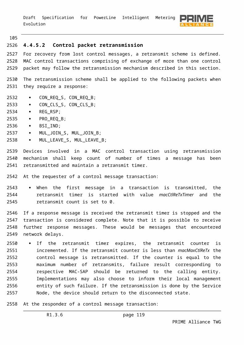
Draft Specification for PowerLine Intelligent Metering Evolution
The Data parameter is a general purpose buffer to be interchanged for the negotiation between the remote CL and the local CL. This parameter is received in the MUL.DATA field of the connection request. In case the CL supports several multicast groups, this Data parameter will be used to uniquely identify the group
The DataLength parameter is the length of the Data parameter in bytes.
If Broadcast is 1, the MAC will immediately issue a MAC_JOIN.confirm primitive since it does not need to perform any end-to-end operation. For a multicast operation the MAC_JOIN.confirm is only sent once signaling with the uplink Service Node/Base Node is complete.
4.5.2.4.3 MAC_JOIN.confirm
The MAC_JOIN.confirm primitive is received to confirm that the MAC_JOIN.request operation has finished.
The semantics of this primitive are as follows:
MAC_JOIN.confirmConHandle, Result
The ConHandle is a unique identifier to uniquely identify the connection being indicated. It has a valid meaning only in the MAC SAP, used to have a reference to this connection between different primitives. The value is only valid if the Result parameter is 0. When the MAC receives packets on this connection, they will be passed upwards using the MAC_DATA.indication primitive with this ConHandle.
The Result parameter indicates the result of multicast group join process. It may have one of the values given in Table 39.
Table 39 – Values of the Result parameter in MAC_JOIN.confirm primitive
Result Description
Success = 0 The connection establishment was successful.
Reject = 1 The connection establishment failed because it was rejected by the upstream Service Node/Base Node.
Timeout = 2 The connection establishment process timed out.
4.5.2.4.4 MAC_JOIN.indication
On the Base Node, the MAC_JOIN.indication is passed from the MAC layer to indicate that a multicast group join was initiated by a Service Node. On a Service Node, it is used to indicate that the Base Node is inviting to join a multicast group.
Depending on device type, this primitive shall have two variants. The first variant below shall be used in Base Nodes and the second variant is for Service Nodes:
MAC_JOIN.indicationConHandle, EUI-48, Type, Data, DataLength
MAC_JOIN.indication(ConHandle, Type, Data, Datalen
R1.3.6 page 119 PRIME Alliance TWG
107239023912392
2393
239423952396
2397
2398
2399
2400
2401240224032404
24052406
2407
2408
240924102411
24122413
2414
2415
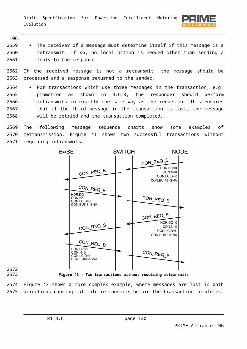
Draft Specification for PowerLine Intelligent Metering Evolution
The ConHandle is a unique identifier interchanged to uniquely identify the multicast group being indicated. It has a valid meaning only in the MAC SAP, used to have a reference to this connection between different primitives.
The EUI-48 parameter indicates which device on the Subnetwork wishes to establish a connection.
The Type parameter is an identifier used to define the type of the Convergence layer that should be used for this request. This parameter is 1 byte long and it is received in the MUL.TYPE field of the connection request.
The Data parameter is a general purpose buffer to be interchanged for the negotiation between the remote CL and the local CL. This parameter is received in the MUL.DATA field of the connection request.
The DataLength parameter is the length of the Data parameter in bytes.
4.5.2.4.5 MAC_JOIN.response
The MAC_JOIN.response is passed to the MAC layer to respond with a MAC_ JOIN.indication. Depending on device type, this primitive could have either of the two forms given below. The first one shall be used in Service Node and the second on in Base Node implementations.
The semantics of this primitive are as follows:
MAC_ JOIN.responseConHandle, Answer
MAC_JOIN.response (ConHandle, EUI, Answer)
The ConHandle parameter is the same as the one that was received in the MAC_ JOIN.indication.
EUI is the EUI-48 of Service Node that requested the multicast group join.
The Answer parameter is used to notify the MAC of the action to be taken for this join request. This parameter may have one of the values depicted below.
Table 40 – Values of the Answer parameter in MAC_ESTABLISH.response primitive
Answer Description
Accept = 0 The multicast group join is accepted.
Reject = 1 The multicast group join is rejected.
4.5.2.5 MAC_LEAVE
4.5.2.5.1 General
The MAC_LEAVE primitives are used to leave a broadcast or multicast connection.
R1.3.6 page 120 PRIME Alliance TWG
108241624172418
2419
242024212422
24232424
2425
2426
242724282429
2430
2431
2432
2433
2434
24352436
2437
2438
2439
2440

Draft Specification for PowerLine Intelligent Metering Evolution
4.5.2.5.2 MAC_LEAVE.request
The MAC_LEAVE.request primitive is used to leave a multicast or broadcast traffic. Depending on device type, this primitive could have either of the two forms given below. The first one shall be used in Service Node and the second on in Base Node implementations.
The semantics of this primitive are as follows:
MAC_LEAVE.requestConHandle
MAC_LEAVE.requestConHandle, EUI
The ConHandle parameter specifies the connection to be left. This handle is the one that was obtained during the MAC_JOIN primitives.
EUI is the EUI-48 of Service Node to remove from multicast group.
4.5.2.5.3 MAC_LEAVE.confirm
The MAC_LEAVE.confirm primitive is received to confirm that the MAC_LEAVE.request operation has finished.
The semantics of this primitive are as follows:
MAC_LEAVE.confirmConHandle, Result
The ConHandle parameter specifies the connection released. This handle is the one that was obtained during the MAC_JOIN primitives.
The Result parameter may have one of the values in Table 41.
Table 41 – Values of the Result parameter in MAC_LEAVE.confirm primitive
Result Description
Success = 0 The connection leave was successful.
Timeout = 2 The connection leave process timed out.
After the reception of the MAC_LEAVE.confirm, the ConHandle is no longer valid and should not be used.
4.5.2.5.4 MAC_LEAVE.indication
The MAC_LEAVE.indication primitive is used to leave a multicast or broadcast traffic. Depending on device type, this primitive could have either of the two forms given below. The first one shall be used in Service Node and the second on in Base Node implementations.
The semantics of this primitive are as follows:
MAC_LEAVE.indicationConHandle
MAC_LEAVE.indicationConHandle, EUI
R1.3.6 page 121 PRIME Alliance TWG
1092441
244224432444
2445
2446
2447
24482449
2450
2451
24522453
2454
2455
24562457
2458
2459
2460
2461
2462
246324642465
2466
2467
2468

Draft Specification for PowerLine Intelligent Metering Evolution
The ConHandle parameter is the same as that received in MAC_JOIN.confirm or MAC_JOIN.indication. This handle is the one that was obtained during the MAC_JOIN primitives.
EUI is the EUI-48 of Service Node to remove from multicast group.
4.5.3 Base Node signalling primitives
4.5.3.1 General
This section specifies MAC-SAP primitives that are only available in the Base Node.
4.5.3.2 MAC_REDIRECT.response
The MAC_REDIRECT.response primitive is used to answer to a MAC_ESTABLISH.indication and redirects the connection from the Base Node to another Service Node on the Subnetwork.
The semantics of this primitive are as follows:
MAC_REDIRECT.reponseConHandle, EUI-48, Data, DateLength
The ConHandle is the one passed in the MAC_ESTABLISH.indication primitive to which it is replying.
EUI-48 indicates the Service Node to which this connection establishment should be forwarded. The Base Node should perform a direct connection setup between the source of the connection establishment and the Service Node indicated by EUI-48.
The Data parameter is a general purpose buffer to be interchanged for the negotiation between the remote CL and the Base Node CL. This parameter is received in the CON.DATA field of the connection request.
The DataLength parameter is the length of the Data parameter in bytes.
Once this primitive has been used, the ConHandle is no longer valid.
4.5.4 Service and Base Nodes data primitives
4.5.4.1 General
The following subsections describe how a Service Node or Base Node passes data between the Convergence layer and the MAC layer.
4.5.4.2 MAC_DATA.request
The MAC_DATA.request primitive is used to initiate the transmission process of data over a connection.
The semantics of the primitive are as follows:
MAC_DATA.requestConHandle, Data, DataLength, Priority
The ConHandle parameter specifies the connection to be used for the data transmission. This handle is the one that was obtained during the connection establishment primitives.
R1.3.6 page 122 PRIME Alliance TWG
11024692470
2471
2472
2473
2474
2475
24762477
2478
2479
2480
248124822483
248424852486
2487
2488
2489
2490
24912492
2493
2494
2495
2496
24972498

Draft Specification for PowerLine Intelligent Metering Evolution
The Data parameter is a buffer of octets that contains the CL data to be transmitted through this connection.
The DataLength parameter is the length of the Data parameter in octets.
Priority indicates the priority of the data to be sent when using the CSMA access scheme, i.e. the parameter only has meaning when the connection was established with CfBytes = 0.
4.5.4.3 MAC_DATA.confirm
The MAC_DATA.confirm primitive is used to confirm that the transmission process of the data has completed.
The semantics of the primitive are as follows:
MAC_DATA.confirmConHandle, Data, Result
The ConHandle parameter specifies the connection that was used for the data transmission. This handle is the one that was obtained during the connection establishment primitives.
The Data parameter is a buffer of octets that contains the CL data that where to be transmitted through this connection.
The Result parameter indicates the result of the transmission. This can take one of the values given in Table42.
Table 42 – Values of the Result parameter in MAC_DATA.confirm primitive
Result Description
Success = 0 The send was successful.
Timeout = 2 The send process timed out.
4.5.4.4 MAC_DATA.indication
The MAC_DATA.indication primitive notifies the reception of data through a connection to the CL.
The semantics of the primitive are as follows:
MAC_DATA.indicationConHandle, Data, DataLength
The ConHandle parameter specifies the connection where the data was received. This handle is the one that was obtained during the connection establishment primitives.
The Data parameter is a buffer of octets that contains the CL data received through this connection.
The DataLength parameter is the length of the Data parameter in octets.
R1.3.6 page 123 PRIME Alliance TWG
11124992500
2501
25022503
2504
25052506
2507
2508
25092510
25112512
25132514
2515
2516
2517
2518
2519
25202521
2522
2523
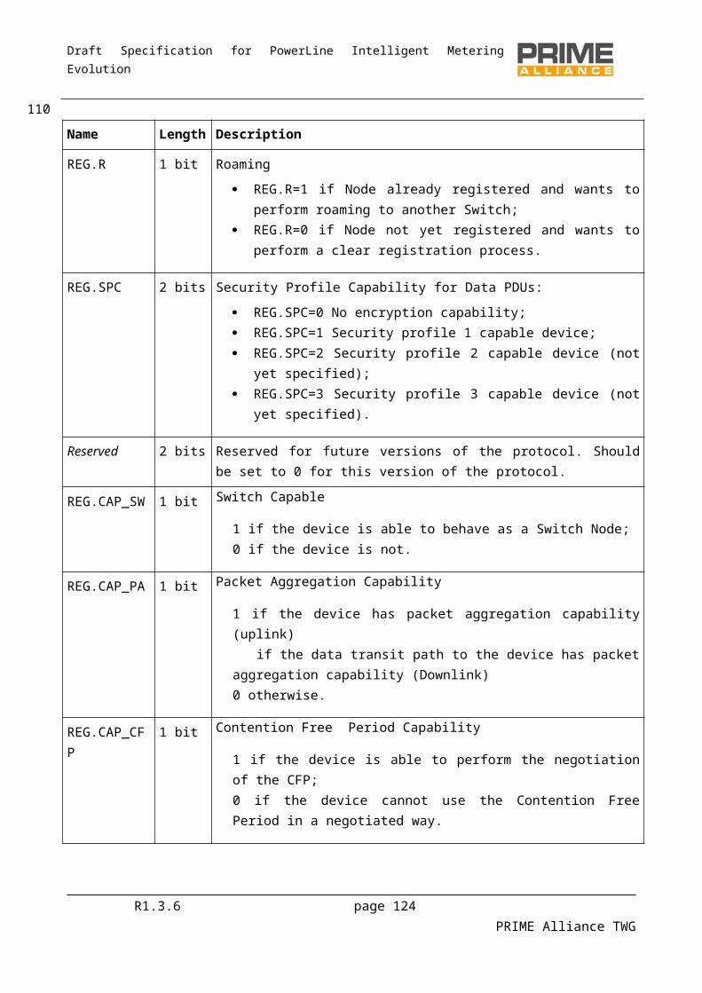
Draft Specification for PowerLine Intelligent Metering Evolution
4.5.5 MAC Layer Management Entity SAPs
4.5.5.1 General
The following primitives are all optional.
The aim is to allow an external management entity to control Registration and Promotion of the Service Node, demotion and Unregistration of a Service Node. The MAC layer would normally perform this automatically; however, in some situations/applications it could be advantageous if this could be externally controlled. Indications are also defined so that an external entity can monitor the status of the MAC.
4.5.5.2 MLME_REGISTER
4.5.5.2.1 General
The MLME_REGISTER primitives are used to perform Registration and to indicate when Registration has been performed.
4.5.5.2.2 MLME_REGISTER.request
The MLME_REGISTER.request primitive is used to trigger the Registration process to a Subnetwork through a specific Switch Node. This primitive may be used for enforcing the selection of a specific Switch Node that may not necessarily be used if the selection is left automatic. The Base Node MLME function does not export this primitive.
The semantics of the primitive could be either of the following:
MLME_REGISTER.request
Invoking this primitive without any parameter simply invokes the Registration process in MAC and leaves the selection of the Subnetwork and Switch Node to MAC algorithms. Using this primitive enables the MAC to perform fully automatic Registration if such a mode is implemented in the MAC.
MLME_REGISTER.requestSNA
The SNA parameter specifies the Subnetwork to which Registration should be performed. Invoking the primitive in this format commands the MAC to register only to the specified Subnetwork.
MLME_REGISTER.requestSID
The SID parameter is the SID (Switch Identifier) of the Switch Node through which Registration needs to be performed. Invoking the primitive in this format commands the MAC to register only to the specified Switch Node.
4.5.5.2.3 MLME_REGISTER.confirm
The MLME_REGISTER.confirm primitive is used to confirm the status of completion of the Registration process that was initiated by an earlier invocation of the corresponding request primitive. The Base Node MLME function does not export this primitive.
The semantics of the primitive are as follows:
R1.3.6 page 124 PRIME Alliance TWG
112
2524
2525
2526
2527252825292530
2531
2532
25332534
2535
2536253725382539
2540
2541
254225432544
2545
25462547
2548
254925502551
2552
255325542555
2556
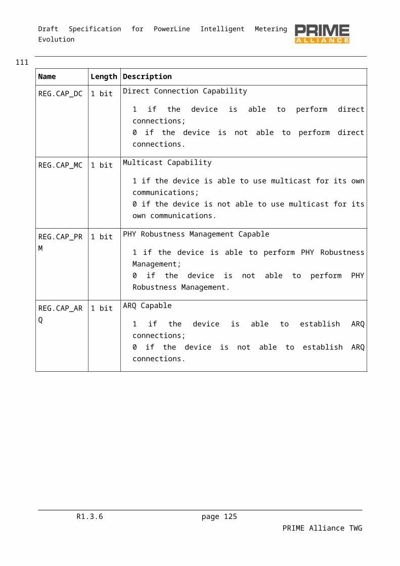
Draft Specification for PowerLine Intelligent Metering Evolution
MLME_REGISTER.confirmResult, SNA, SID
The Result parameter indicates the result of the Registration. This can take one of the values given in Table43.
Table 43 – Values of the Result parameter in MLME_REGISTER.confirm primitive
Result Description
Done = 0 Registration to specified SNA through specified Switch is completed successfully.
Timeout =2 Registration request timed out .
Rejected=1 Registration request is rejected by Base Node of specified SNA.
NoSNA=8 Specified SNA is not within range.
NoSwitch=9 Switch Node with specified EUI-48 is not within range.
The SNA parameter specifies the Subnetwork to which Registration is performed. This parameter is of significance only if Result=0.
The SID parameter is the SID (Switch Identifier) of the Switch Node through which Registration is performed. This parameter is of significance only if Result=0.
4.5.5.2.4 MLME_REGISTER.indication
The MLME_REGISTER.indication primitive is used to indicate a status change in the MAC. The Service Node is now registered to a Subnetwork.
The semantics of the primitive are as follows:
MLME_REGISTER.indicationSNA, SID
The SNA parameter specifies the Subnetwork to which Registration is performed.
The SID parameter is the SID (Switch Identifier) of the Switch Node through which Registration is performed.
4.5.5.3 MLME_UNREGISTER
4.5.5.3.1 General
The MLME_UNREGISTER primitives are used to perform deregistration and to indicate when deregistration has been performed.
4.5.5.3.2 MLME_UNREGISTER.request
The MLME_UNREGISTER.request primitive is used to trigger the Unregistration process. This primitive may be used by management entities if they require the Node to unregister for some reason (e.g. register through another Switch Node or to another Subnetwork). The Base Node MLME function does not export this primitive.
The semantics of the primitive are as follows:
R1.3.6 page 125 PRIME Alliance TWG
1132557
25582559
2560
25612562
25632564
2565
25662567
2568
2569
2570
25712572
2573
2574
25752576
2577
2578257925802581
2582
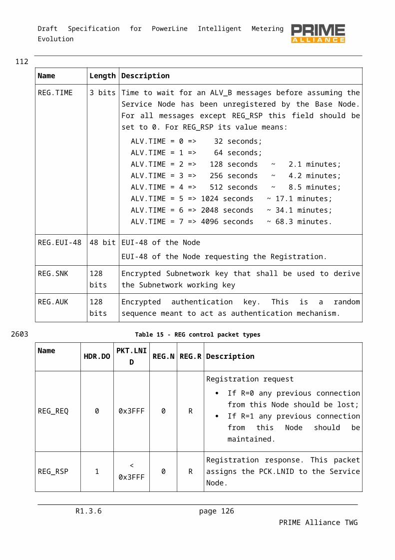
Draft Specification for PowerLine Intelligent Metering Evolution
MLME_UNREGISTER.request
4.5.5.3.3 MLME_UNREGISTER.confirm
The MLME_UNREGISTER.confirm primitive is used to confirm the status of completion of the unregister process initiated by an earlier invocation of the corresponding request primitive. The Base Node MLME function does not export this primitive.
The semantics of the primitive are as follows:
MLME_UNREGISTER.confirmResult
The Result parameter indicates the result of the Registration. This can take one of the values given in Table44.
Table 44 – Values of the Result parameter in MLME_UNREGISTER.confirm primitive
Result Description
Done = 0 Unregister process completed successfully.
Timeout =2 Unregister process timed out .
Redundant=10 The Node is already in Disconnected functional state and does not need to unregister.
On generation of MLME_UNREGISTER.confirm, the MAC layer shall not perform any automatic actions that may invoke the Registration process again. In such cases, it is up to the management entity to restart the MAC functionality with appropriate MLME_REGISTER primitives.
4.5.5.3.4 MLME_UNREGISTER.indication
The MLME_UNREGISTER.indication primitive is used to indicate a status change in the MAC. The Service Node is no longer registered to a Subnetwork.
The semantics of the primitive are as follows:
MLME_UNREGISTER.indication
4.5.5.4 MLME_PROMOTE
4.5.5.4.1 General
The MLME_PROMOTE primitives are used to perform promotion and to indicate when promotion has been performed.
4.5.5.4.2 MLME_PROMOTE.request
The MLME_PROMOTE.request primitive is used to trigger the promotion process in a Service Node that is in a Terminal functional state. This primitive may be used by management entities to enforce promotion in cases where the Node’s default functionality does not automatically start the process. Implementations may use such triggered promotions to optimize Subnetwork topology from time to time.
R1.3.6 page 126 PRIME Alliance TWG
1142583
2584
258525862587
2588
2589
25902591
2592
2593
259425952596
2597
25982599
2600
2601
2602
2603
26042605
2606
2607260826092610
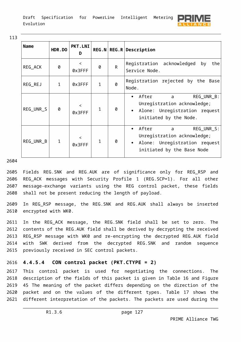
Draft Specification for PowerLine Intelligent Metering Evolution
The semantics of the primitive are as follows:
MLME_PROMOTE.request
The value of PRO.PNA in the promotion message sent to the Base Node is undefined and implementation-specific.
4.5.5.4.3 MLME_PROMOTE.confirm
The MLME_PROMOTE.confirm primitive is used to confirm the status of completion of a promotion process that was initiated by an earlier invocation of the corresponding request primitive.
The semantics of the primitive are as follows:
MLME_PROMOTE.confirmResult
The Result parameter indicates the result of the Registration. This can take one of the values given in Table45.
Table 45 – Values of the Result parameter in MLME_PROMOTE.confirm primitive
Result Description
Done = 0 Node is promoted to Switch function successfully.
Timeout =1 Promotion process timed out .
Rejected=2 The Base Node rejected promotion request.
Redundant=10 This device is already functioning as Switch Node.
4.5.5.4.4 MLME_PROMOTE.indication
The MLME_PROMOTE.indication primitive is used to indicate a status change in the MAC. The Service NodeService Node is now operating as a Switch.
The semantics of the primitive are as follows:
MLME_PROMOTE.indication
4.5.5.5 MLME_DEMOTE
4.5.5.5.1 General
The MLME_DEMOTE primitives are used to perform demotion and to indicate when demotion has been performed.
4.5.5.5.2 MLME_DEMOTE.request
The MLME_DEMOTE.request primitive is used to trigger a demotion process in a Service NodeService Node that is in a Switch functional state. This primitive may be used by management entities to enforce demotion in cases where the Node’s default functionality does not automatically perform the process.
The semantics of the primitive are as follows:R1.3.6 page 127 PRIME Alliance TWG
1152611
2612
26132614
2615
26162617
2618
2619
26202621
2622
2623
26242625
2626
2627
2628
2629
26302631
2632
263326342635
2636
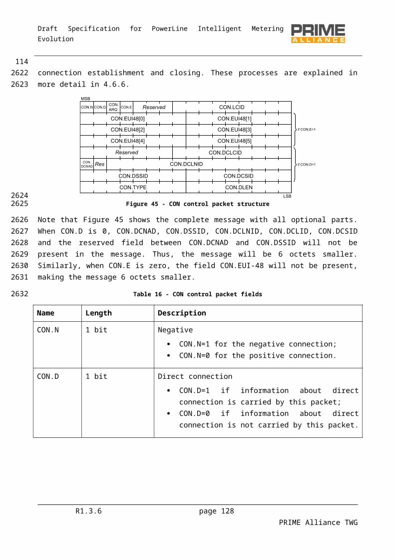
Draft Specification for PowerLine Intelligent Metering Evolution
MLME_DEMOTE.request
4.5.5.5.3 MLME_DEMOTE.confirm
The MLME_DEMOTE.confirm primitive is used to confirm the status of completion of a demotion process that was initiated by an earlier invocation of the corresponding request primitive.
The semantics of the primitive are as follows:
MLME_DEMOTE.confirmResult
The Result parameter indicates the result of the demotion. This can take one of the values given in Table46.
Table 46 – Values of the Result parameter in MLME_DEMOTE.confirm primitive
Result Description
Done = 0 Node is demoted to Terminal function successfully.
Timeout =1 Demotion process timed out .
Redundant=10 This device is already functioning as Terminal Node.
When a demotion has been triggered using the MLME_DEMOTE.request, the Terminal will remain demoted.
4.5.5.5.4 MLME_DEMOTE.indication
The MLME_DEMOTE.indication primitive is used to indicate a status change in the MAC. The Service NodeService Node is now operating as a Terminal.
The semantics of the primitive are as follows:
MLME_DEMOTE.indication
4.5.5.6 MLME_RESET
4.5.5.6.1 General
The MLME_RESET primitives are used to reset the MAC into a known good status.
4.5.5.6.2 MLME_RESET.request
The MLME_RESET.request primitive results in the flushing of all transmit and receive buffers and the resetting of all state variables. As a result of invoking of this primitive, a Service Node will transit from its present functional state to the Disconnected functional state.
The semantics of the primitive are as follows:
MLME_RESET.request
R1.3.6 page 128 PRIME Alliance TWG
1162637
2638
26392640
2641
2642
26432644
2645
2646
26472648
2649
26502651
2652
2653
2654
2655
2656
2657
265826592660
2661
2662
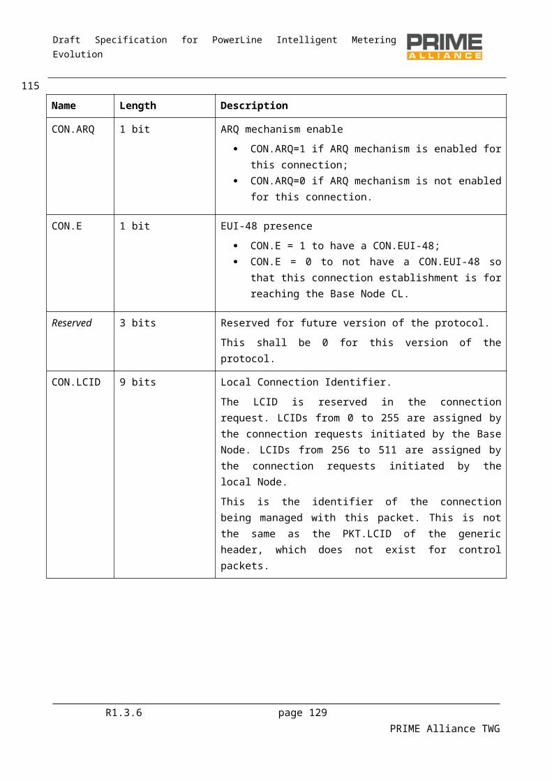
Draft Specification for PowerLine Intelligent Metering Evolution
4.5.5.6.3 MLME_RESET.confirm
The MLME_RESET.confirm primitive is used to confirm the status of completion of a reset process that was initiated by an earlier invocation of the corresponding request primitive. On the successful completion of the reset process, the MAC entity shall restart all functions starting from the search for a Subnetwork (4.3.1).
The semantics of the primitive are as follows:
MLME_RESET.confirmResult
The Result parameter indicates the result of the reset. This can take one of the values given below.
Table 47 – Values of the Result parameter in MLME_RESET.confirm primitive
Result Description
Done = 0 MAC reset completed successfully.
Failed =1 MAC reset failed due to internal implementation reasons.
4.5.5.7 MLME_GET
4.5.5.7.1 General
The MLME_GET primitives are used to retrieve individual values from the MAC, such as statistics.
4.5.5.7.2 MLME_GET.request
The MLME_GET.request queries information about a given PIB attribute.
The semantics of the primitive are as follows:
MLME_GET.requestPIBAttribute
The PIBAttribute parameter identifies specific attributes as listed in the Id fields of tables that list PIB attributes (Section 6.2.3).
4.5.5.7.3 MLME_GET.confirm
The MLME_GET.confirm primitive is generated in response to the corresponding MLME_GET.request primitive.
The semantics of this primitive are as follows:
MLME_GET.confirmstatus, PIBAttribute, PIBAttributeValue
The status parameter reports the result of requested information and can have one of the values given in Table 48.
Table 48 – Values of the status parameter in MLME_GET.confirm primitive
R1.3.6 page 129 PRIME Alliance TWG
1172663
2664266526662667
2668
2669
2670
2671
2672
2673
2674
2675
2676
2677
2678
26792680
2681
26822683
2684
2685
26862687
2688
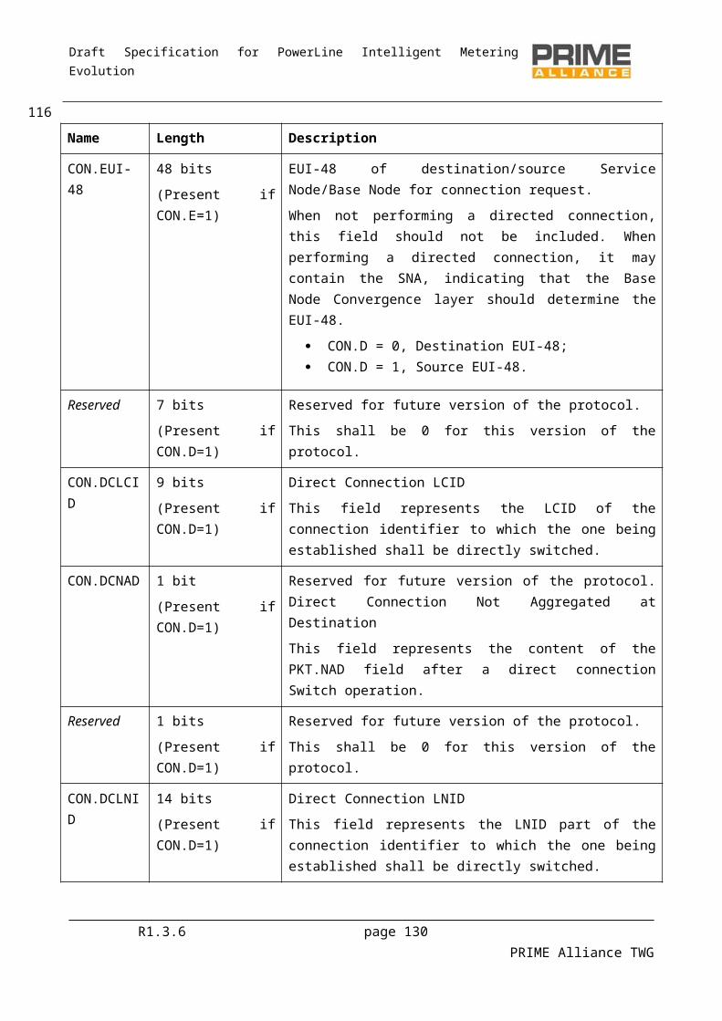
Draft Specification for PowerLine Intelligent Metering Evolution
Result Description
Done = 0 Parameter read successfully.
Failed =1 Parameter read failed due to internal implementation reasons.
BadAttr=11 Specified PIBAttribute is not supported.
The PIBAttribute parameter identifies specific attributes as listed in Id fields of tables that list PIB attributes (Section 6.2.3.5).
The PIBAttributeValue parameter specifies the value associated with a given PIBAttribute
4.5.5.8 MLME_LIST_GET
4.5.5.8.1 General
The MLME_LIST_GET primitives are used to retrieve a list of values from the MAC.
4.5.5.8.2 MLME_LIST_GET.request
The MLME_LIST_GET.request queries for a list of values pertaining to a specific class. This special class of PIB attributes are listed in Table 96.
The semantics of the primitive are as follows:
MLME_LIST_GET.requestPIBListAttribute
The PIBListAttribute parameter identifies a specific list that is requested by the management entity. The possible values of PIBListAttribute are listed in 6.2.3.5.
4.5.5.8.3 MLME_LIST_GET.confirm
The MLME_LIST_GET.confirm primitive is generated in response to the corresponding MLME_LIST_GET.request primitive.
The semantics of this primitive are as follows:
MLME_LIST_GET.confirmstatus, PIBListAttribute, PIBListAttributeValue
The status parameter reports the result of requested information and can have one of the values given in Table 49
Table 49 – Values of the status parameter in MLME_LIST_GET.confirm primitive
Result Description
Done = 0 Parameter read successfully.
Failed =1 Parameter read failed due to internal implementation reasons.
BadAttr=11 Specified PIBListAttribute is not supported.
R1.3.6 page 130 PRIME Alliance TWG
118
2689
26902691
2692
2693
2694
2695
2696
26972698
2699
2700
27012702
2703
27042705
2706
2707
27082709
2710
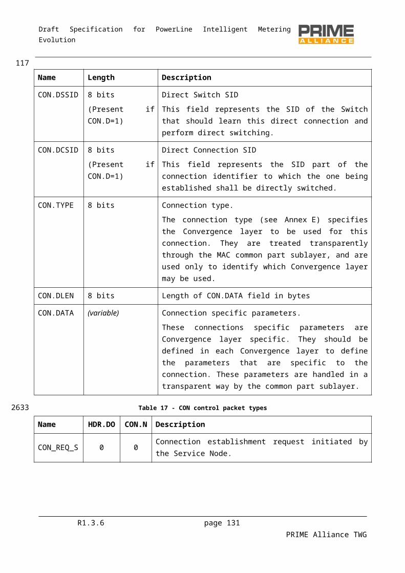
Draft Specification for PowerLine Intelligent Metering Evolution
The PIBListAttribute parameter identifies a specific list as listed in the Id field of Table 96.
The PIBListAttributeValue parameter contains the actual listing associated with a given PIBListAttribute
4.5.5.9 MLME_SET
4.5.5.9.1 General
The MLME_SET primitives are used to set configuration values in the MAC.
4.5.5.9.2 MLME_SET.request
The MLME_SET.requests information about a given PIB attribute.
The semantics of the primitive are as follows:
MLME_SET.requestPIBAttribute, PIBAttributeValue
The PIBAttribute parameter identifies a specific attribute as listed in the Id fields of tables that list PIB attributes (Section 6.2.3).
The PIBAttributeValue parameter specifies the value associated with given PIBAttribute.
4.5.5.9.3 MLME_SET.confirm
The MLME_SET.confirm primitive is generated in response to the corresponding MLME_SET.request primitive.
The semantics of this primitive are as follows:
MLME_SET.confirmresult
The result parameter reports the result of requested information and can have one of the values given in Table 50
Table 50 – Values of the Result parameter in MLME_SET.confirm primitive
Result Description
Done = 0 Given value successfully set for specified attribute.
Failed =1 Failed to set the given value for specified attribute.
BadAttr=11 Specified PIBAttribute is not supported.
OutofRange=12 Specified PIBAttributeValue is out of acceptable range.
ReadOnly=13 Specified PIBAttributeValue is read only.
The PIBAttribute parameter identifies a specific attribute as listed in the Id fields of tables that list PIB attributes (Section 6.2.3).
R1.3.6 page 131 PRIME Alliance TWG
1192711
2712
2713
2714
2715
2716
2717
2718
2719
2720
27212722
2723
2724
27252726
2727
2728
27292730
2731
2732
27332734
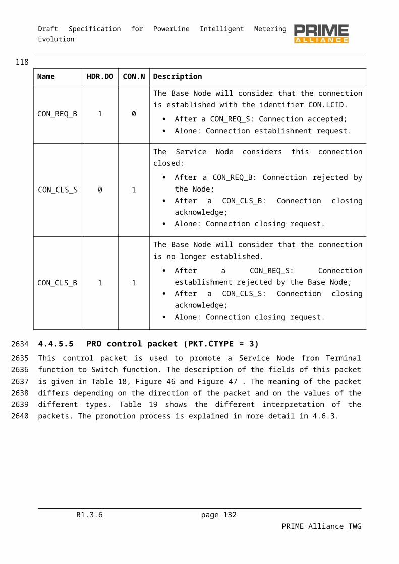
Draft Specification for PowerLine Intelligent Metering Evolution
The PIBAttributeValue parameter specifies the value associated with a given PIBAttribute.
4.6 MAC procedures
4.6.1 RegistrationThe initial Service Node start-up (4.3.1) is followed by a Registration process. A Service Node in a Disconnected functional state shall transmit a REG control packet to the Base Node in order to get itself included in the Subnetwork. Since no LNID or SID is allocated to a Service Node at this stage, the PKT.LNID field shall be set to all 1s and the PKT.SID field shall contain the SID of the Switch Node through which it seeks attachment to the Subnetwork.
Base Nodes may use a Registration request as an authentication mechanism. However this specification does not recommend or forbid any specific authentication mechanism and leaves this choice to implementations.
For all successfully accepted Registration requests, the Base Node shall allocate an LNID that is unique within the domain of the Switch Node through which the attachment is realized. This LNID shall be indicated in the PKT.LNID field of response (REG_RSP). The assigned LNID, in combination with the SID of the Switch Node through which the Service Node is registered, would form the NID of the registering Node.
Registration is a three-way process. The REG_RSP shall be acknowledged by the receiving Service Node with a REG_ACK message.
Figure 59 represents a successful Registration process and Figure 60 shows a Registration request that is rejected by the Base Node. Details on specific fields that distinguish one Registration message from the other are given in Table 15.
The REG control packet, in all its usage variants, is transmitted unencrypted, but specified fields (REG.SNK and REG.AUK) are encrypted with context-specific encryption keys as explained in Section 4.4.5.3. The encryption of REG.AUK in REG_RSP, its decryption at the receiving end and subsequent encrypted retransmission using a different encryption key authenticates that the REG_ACK is from the intended destination.
Figure 59 – Registration process accepted
R1.3.6 page 132 PRIME Alliance TWG
1202735
2736
2737
27382739274027412742
274327442745
2746274727482749
27502751
275227532754
27552756275727582759
27602761
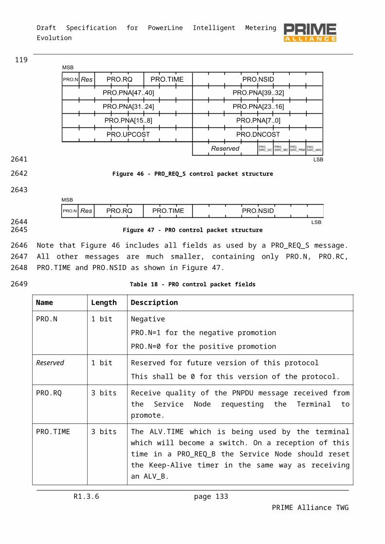
Draft Specification for PowerLine Intelligent Metering Evolution
Figure 60 – Registration process rejected
When assigning an LNID, the Base Node shall not reuse an LNID released by an unregister process until after (macMaxCtlReTx +1) * macCtlReTxTimer. seconds, to ensure that all retransmit packets have left the Subnetwork. Similarly, the Base Node shall not reuse an LNID freed by the Keep-Alive process until T keep_alive
seconds have passed, using the last known acknowledged Tkeep_alive value, or if larger, the last unacknowledged Tkeep_alive, for the Service Node using the LNID.
During network startup where the whole network is powered on at once, there will be considerable contention for the medium. It is recommended, but optional, that randomness is added to the first transmission of REQ_REQ and all subsequent retransmissions. A random delay of maximum duration of 10% of macCtlReTxTimer may be imposed before the first REG_REQ message, and a similar random delay of up to 10% of macCtlReTxTimer maybe added to each retransmission.
4.6.2 Unregistering processAt any point in time, either the Base Node or the Service Node may decide to close an existing registration. This version of the specification does not provide provision for rejecting an unregister request. The Service Node or Base Node that receives an unregister request shall acknowledge its receipt and take appropriate actions.
Following a successful unregister, a Service Node shall move back from its present functional state to a Disconnected functional state and the Base Node may re-use any resources that were reserved for the unregistering Node.
Figure 61 shows a successful unregister process initiated from a Service Node and Figure 62 shows an unregister process initiated from the Base Node. Details on specific fields that identify unregister requests in REG control packets are given in Table 15
Figure 61 – Unregistering process initiated by a Terminal Node
R1.3.6 page 133 PRIME Alliance TWG
121
27622763
27642765276627672768
27692770277127722773
2774
2775277627772778
277927802781
278227832784
2785
27862787

Draft Specification for PowerLine Intelligent Metering Evolution
Figure 62 – Unregistering process initiated by the Base Node
4.6.3 Promotion processA Node that cannot reach any existing Switch may send promotion-needed frames so that a Terminal can be promoted and begin to switch. During this process, a Node that cannot reach any existing Switch may send PNPDUs so that a nearby Terminal can be promoted and begin to act as a Switch. During this process, a Terminal will receive PNPDUs and at its discretion, generate PRO_REQ control packets to the Base Node.
The Base Node examines the promotion requests during a period of time. It may use the address of the new Terminal, provided in the promotion-request packet, to decide whether or not to accept the promotion. It will decide which Node shall be promoted, if any, sending a promotion response. The other Nodes will not receive any answer to the promotion request to avoid Subnetwork saturation. Eventually, the Base Node may send a rejection if any special situation occurs. If the Subnetwork is specially preconfigured, the Base Node may send Terminal Node promotion requests directly to a Terminal Node.
When a Terminal Node requests promotion, the PRO.NSID field in the PRO_REQ_S message shall be set to all 1s. The PRO.NSID field shall contain an LSID allocated to the promoted Node in the PRO_REQ_B message. The acknowledging Switch Node shall set the PRO.NSID field in its PRO_ACK to the newly allocated LSID. This final PRO_ACK shall be used by intermediate Switch Nodes to update their switching tables as described in 4.3.5.2.
When reusing LSIDs that have been released by a demotion process, the Base Node should not allocate the LSID until after (macMaxCtlReTx + 1) * macCtlReTxTimer. seconds to ensure all retransmit packets that might use that LSID have left the Subnetwork. Similarly, the Base Node shall not reuse an LNID freed by the Keep-Alive process until Tkeep_alive seconds have passed, using the last known acknowledged Tkeep_alive value, or if larger, the last unacknowledged Tkeep_alive, for the Service Node using the LNID.
R1.3.6 page 134 PRIME Alliance TWG
122
27882789
2790
2791279227932794
279527962797279827992800
28012802280328042805
28062807280828092810
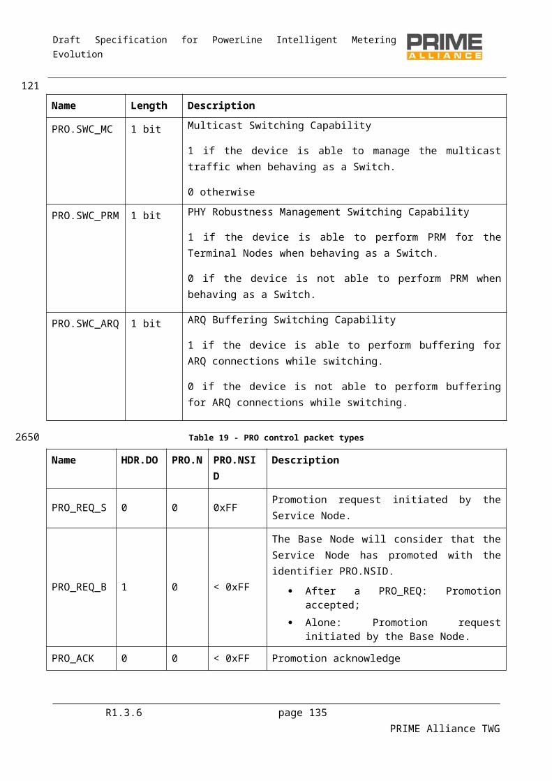
Draft Specification for PowerLine Intelligent Metering Evolution
Figure 63 – Promotion process initiated by a Service Node
Figure 64 – Promotion process rejected by the Base Node
R1.3.6 page 135 PRIME Alliance TWG
123
28112812
2813
28142815
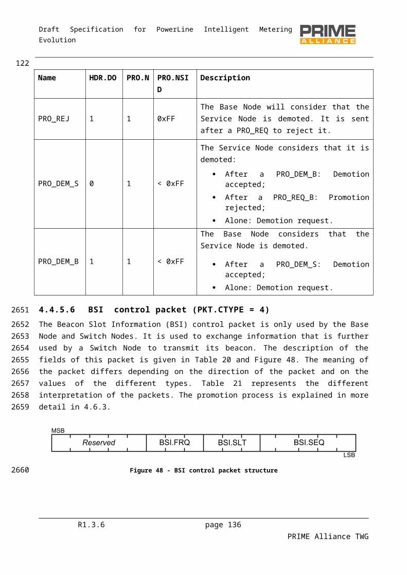
Draft Specification for PowerLine Intelligent Metering Evolution
Figure 65 – Promotion process initiated by the Base Node
Figure 66 – Promotion process rejected by a Service Node
4.6.4 Demotion processThe Base Node or a Switch Node may decide to discontinue a switching function at any time. The demotion process provides for such a mechanism. The PRO control packet is used for all demotion transactions.
The PRO.NSID field shall contain the SID of the Switch Node that is being demoted as part of the demotion transaction. The PRO.PNA field is not used in any demotion process transaction and its contents are not interpreted at either end.
Following the successful completion of a demotion process, a Switch Node shall immediately stop the transmission of beacons and change from a Switch functional state to a Terminal functional state. The Base Node may reallocate the LSID and Beacon Slot used by the demoted Switch after (macMaxCtlReTx + 1) * macCtlReTxTimer seconds to other Terminal Nodes requesting promotion.
The present version of this specification does not specify any explicit message to reject a demotion requested by a peer at the other end.
R1.3.6 page 136 PRIME Alliance TWG
124
28162817
28182819
2820
28212822
282328242825
2826282728282829
28302831
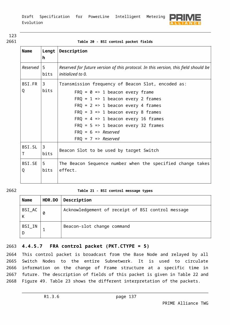
Draft Specification for PowerLine Intelligent Metering Evolution
Figure 67 – Demotion process initiated by a Service Node
Figure 68 – Demotion process initiated by the Base Node
4.6.5 Keep-Alive processThe Keep-Alive process is used to detect when a Service Node has left the Subnetwork because of changes to the network configuration or because of fatal errors it cannot recover from.
When the Service Node receives the REG_RSP packet it uses the REG.TIME field to start a timer Tkeep_alive. For every ALV_B it receives, it restarts this timer using the value from ALV.TIME. It should also send an ALV_S to the Base Node. If the timer ever expires, the Service Node assumes it has been unregistered by the Base Node. The message PRO_REQ does also reset the Keep-Alive timer to the PRO.TIME value.
Each switch along the path of a ALV_B message takes should keep a copy of the PRO.TIME and then ALV.TIME for each Switch Node below it in the tree. When the switch does not receive an ALV_S message from a Service Node below it for Tkeep_alive as defined in PRO.TIME and ALV.TIME it should remove the Switch Node entry from its switch table. See section 4.3.5.2 for more information on the switching table. Additionally a Switch Node may use the REG.TIME and ALV.TIME to consider also every Service Node Registration status and take it into account for the switching table.
For every ALV_S or ALV_B message sent by the Base Node or Service Node, the counter ALV.TXCNT should be incremented before the message is sent. This counter is expected to wrap around. For every ALV_B or ALV_S message received by the Service Node or the Base Node the counter ALV.RXCNT should be incremented. This counter is also expected to wrap around. These two counters are placed into the ALV_S and ALV_B messages. The Base Node should keep a ALV.TXCNT and ALV.RXCNT separated counter for each Service Node. These counters are reset to zero in the Registration process.
R1.3.6 page 137 PRIME Alliance TWG
125
28322833
28342835
2836
28372838
2839284028412842
284328442845284628472848
284928502851285228532854
2855
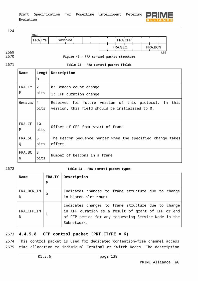
Draft Specification for PowerLine Intelligent Metering Evolution
The algorithm used by the Base Node to determine when to send ALV_B messages to registered Service Nodes and how to determine the value ALV.TIME and REG.TIME is not specified here.
4.6.6 Connection management
4.6.6.1 Connection establishment
Connection establishment works end-to-end, connecting the application layers of communicating peers. Owing to the tree topology, most connections in a Subnetwork will involve the Base Node at one end and a Service Node at the other. However, there may be cases when two Service Nodes within a Subnetwork need to establish connections. Such connections are called direct connections and are described in section 4.3.6.
All connection establishment messages use the CON control packet. The various control packets types and specific fields that unambiguously identify them are given in Table 17.
Each successful connection established on the Subnetwork is allocated an LCID. The Base Node shall allocate an LCID that is unique for a given LNID.
Note. Either of the negotiating ends may decide to reject a connection establishment request. The receipt of a connection rejection does not amount to any restrictions on making future connection requests; it may however be advisable.
Figure 69 – Connection establishment initiated by a Service Node
Figure 70 – Connection establishment rejected by the Base Node
R1.3.6 page 138 PRIME Alliance TWG
12628562857
2858
2859
28602861286228632864
28652866
28672868
286928702871
28722873
28742875
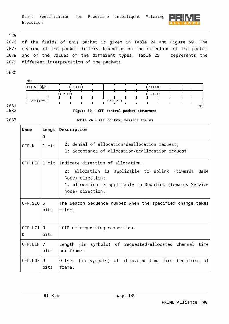
Draft Specification for PowerLine Intelligent Metering Evolution
Figure 71 – Connection establishment initiated by the Base Node
Figure 72 – Connection establishment rejected by a Service Node
4.6.6.2 Connection closing
Either peer at both ends of a connection may decide to close the connection at any time. The CON control packet is used for all messages exchanged in the process of closing a connection. Only the CON.N field in the CON control packet is relevant in closing an active connection.
A connection closure request from one end is acknowledged by the other end before the connection is considered closed. The present version of this specification does not have any explicit message for rejecting a connection termination requested by a peer at the other end.
Figure 73 and Figure 74 show message exchange sequences in a connection closing process.
Figure 73 – Disconnection initiated by a Service Node
R1.3.6 page 139 PRIME Alliance TWG
127
28762877
28782879
2880
288128822883
288428852886
2887
28882889
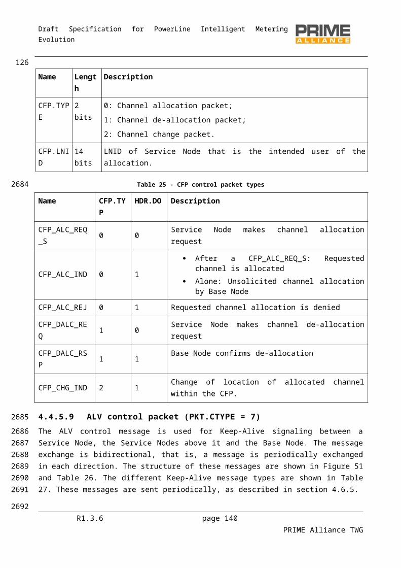
Draft Specification for PowerLine Intelligent Metering Evolution
Figure 74 – Disconnection initiated by the Base Node
4.6.7 Multicast group management
4.6.7.1 General
The joining and leaving of a multicast group can be initiated by the Base Node or the Service Node. The MUL control packet is used for all messages associated with multicast and the usual retransmit mechanism for control packets is used. These control messages are unicast between the Base Node and the Service Node.
4.6.7.2 Group Join
Multicast group join maybe initiated from either the Base Node or Service Node. A device shall not start a new join procedure before an existing join procedure started by itself is completed.
Certain applications may require the Base Node to selectively invite certain Service Nodes to join a specific multicast group. In such cases, the Base Node starts a new group and invites Service Nodes as required by application.
Successful and failed group joins initiated from Base Node are shown in Figure 75 and Figure 76
R1.3.6 page 140 PRIME Alliance TWG
128
28902891
2892
2893
2894289528962897
2898
28992900
290129022903
2904
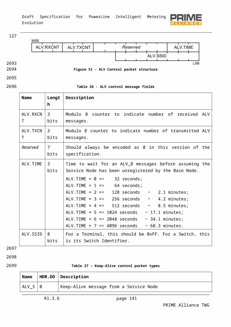
Draft Specification for PowerLine Intelligent Metering Evolution
Figure 75 – Successful group join initiated by Base Node
R1.3.6 page 141 PRIME Alliance TWG
129
2905
2906
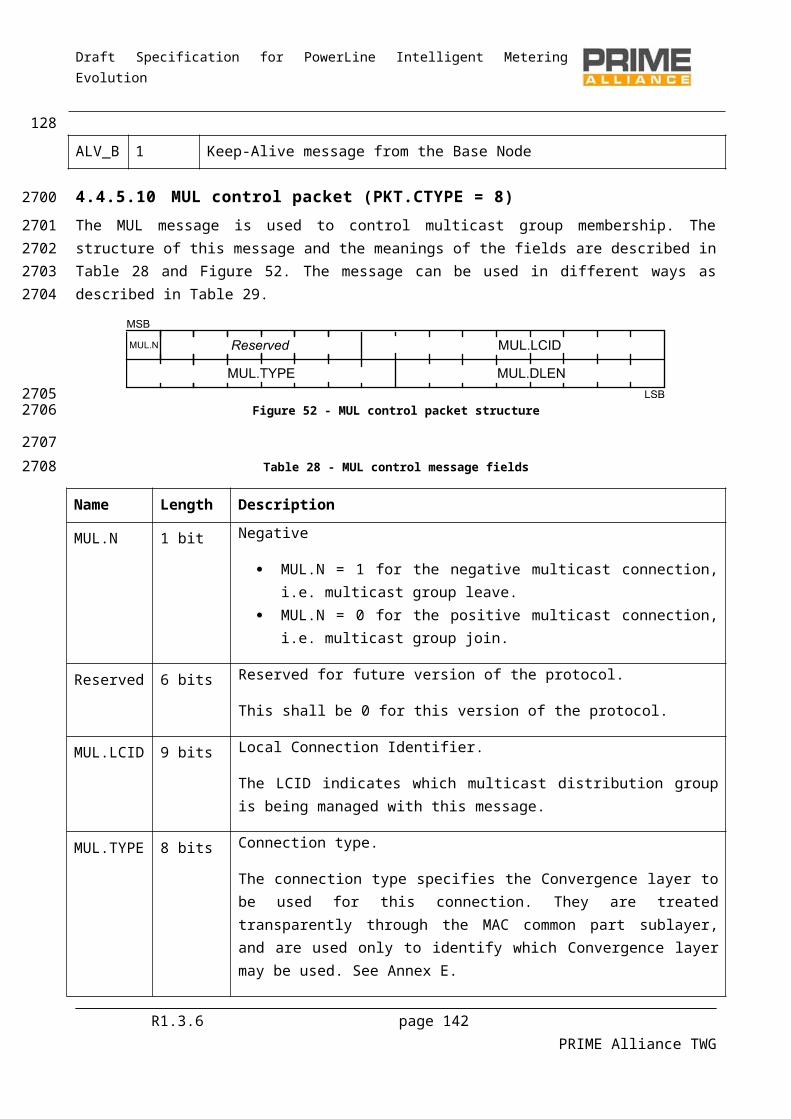
Draft Specification for PowerLine Intelligent Metering Evolution
Figure 76 – Failed group join initiated by Base Node
Successful and failed group joins initiated from Service Node are shown in Figure 77 and Figure 78
R1.3.6 page 142 PRIME Alliance TWG
130
2907
2908
2909
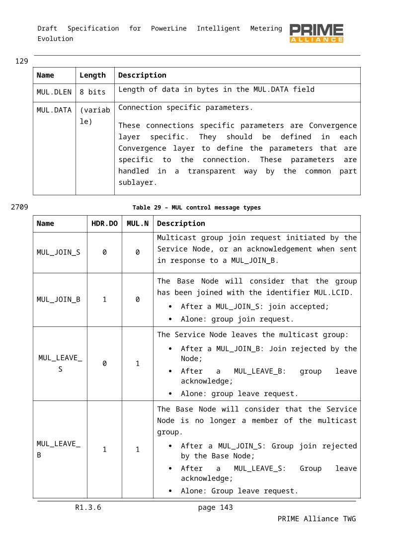
Draft Specification for PowerLine Intelligent Metering Evolution
Figure 77 – Successful group join initiated by Service Node
R1.3.6 page 143 PRIME Alliance TWG
131
2910
2911
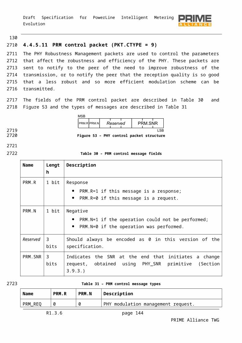
Draft Specification for PowerLine Intelligent Metering Evolution
Figure 78 – Failed group join initiated by Service Node.
4.6.7.3 Group Leave
Leaving a multicast group operates in the same way as connection removal. Either the Base Node or Service Node may decide to leave the group. A notable difference in the group leave process as compared to a group join is that there is no message sequence for rejecting a group leave request.
R1.3.6 page 144 PRIME Alliance TWG
132
2912
2913
2914
2915
291629172918

Draft Specification for PowerLine Intelligent Metering Evolution
Figure 79 – Leave initiated by the Service Node
Figure 80 – Leave initiated by the Base Node
4.6.8 PHY Robustness Management
4.6.8.1 General
The PHY layer has several parameters that affect the performance of the transmission: power transmission, modulation schema (constellation mapping and convolutional encoding). The transmitter needs feedback about the reception quality to adjust its transmission parameters. This feedback is sent using PRM control packets.
4.6.8.2 PHY robustness notification need detection
There are several sources of information that may be used to detect whether or not the robustness of the PHY is the right one:
Received packets with invalid CRC. ARQ retransmissions. Control packet retransmissions. PRM requests sent by other Nodes to the same Switch Node (in the case of Node-to-switch
notifications). PRM responses.
R1.3.6 page 145 PRIME Alliance TWG
133
29192920
29212922
2923
2924
2925292629272928
2929
29302931
293229332934293529362937
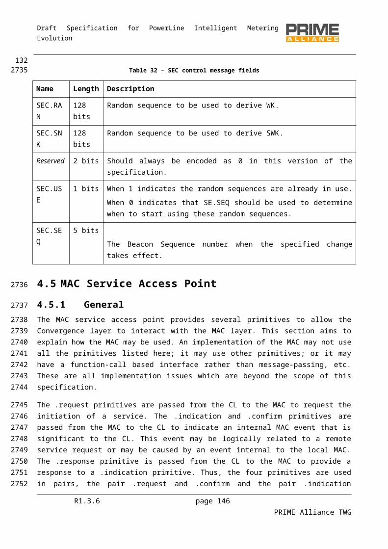
Draft Specification for PowerLine Intelligent Metering Evolution
This information may be used to decide when to notify that the robustness of the PHY should be changed. This notification may be performed from a Service Node to a Switch Node and from a Switch Node to a Service Node. For this purpose, the Base Node works as the root Switch, in exactly the same way the other Switch Nodes do.
4.6.8.3 PHY robustness notification
Figure 81 – PHY robustness management requested by the Switch Node
Figure 82 – PHY robustness management requested by the Service Node
4.6.8.4 PHY robustness changing
From the PHY point of view there are several parameters that may be adjusted and which affect the transmission robustness: the transmission power and modulation parameters (convolutional encoding and constellation). As a general rule the following rules should be followed:
Increase robustness: increase the power and, if it is not possible, improve the modulation scheme robustness (reducing throughput).
Reduce robustness: reduce the modulation scheme robustness (increasing throughput) and, if it is not possible, reduce the transmission power.
R1.3.6 page 146 PRIME Alliance TWG
1342938293929402941
2942
2943
29442945
2946
29472948
2949
2950
295129522953
2954295529562957
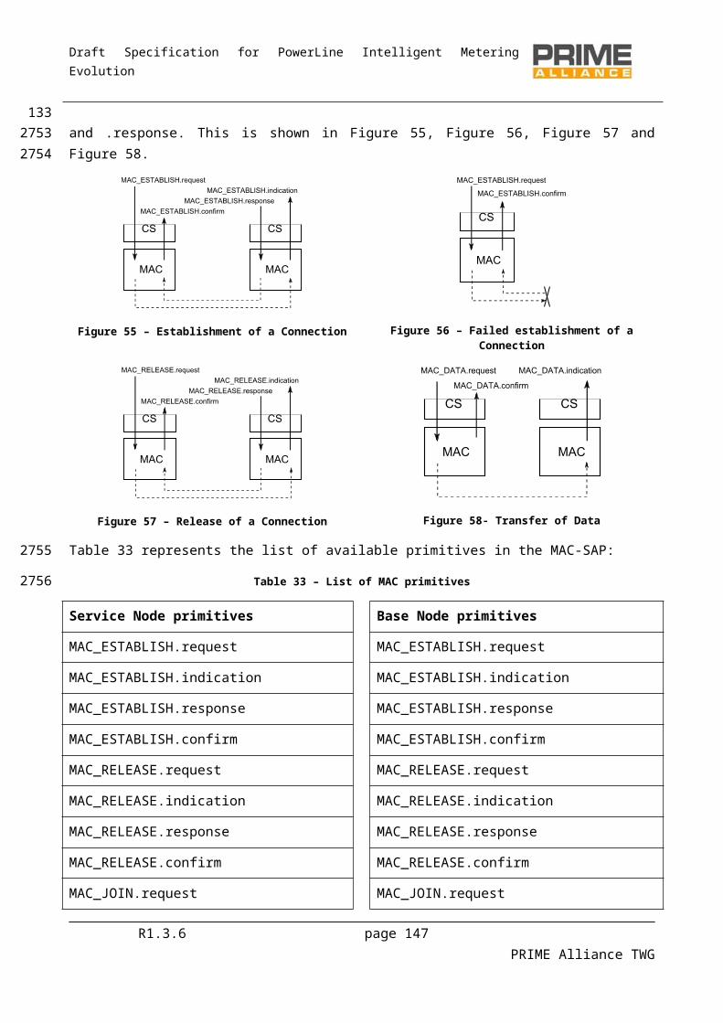
Draft Specification for PowerLine Intelligent Metering Evolution
4.6.9 Channel allocation and deallocationFigure 83 below shows a successful channel allocation sequence. All channel allocation requests are forwarded to the Base Node. Note that in order to assure a contention-free channel allocation along the entire path, the Base Node allocates non-overlapping times to intermediate Switch Nodes. In a multi-level Subnetwork, the Base Node may also reuse the allocated time at different levels. While reusing the said time, the Base Node needs to ensure that the levels that use the same time slots have sufficient separation so that there is no possible interference.
Figure 83 – Successful allocation of CFP period
Figure 84 below shows a channel de-allocation request from a Terminal device and the resulting confirmation from the Base Node.
Figure 84 – Successful channel de-allocation sequence
Figure 85 below shows a sequence of events that may lead to a Base Node re-allocation contention-free slot to a Terminal device that already has slots allocated to it. In this example, a de-allocation request from Terminal-2 resulted in two changes: firstly, in global frame structure, this change is conveyed to the Subnetwork in the FRA_CFP_IND packet; secondly, it is specific to the time slot allocated to Terminal-1 within the CFP.
R1.3.6 page 147 PRIME Alliance TWG
135
2958
295929602961296229632964
29652966
29672968
29692970
29712972297329742975
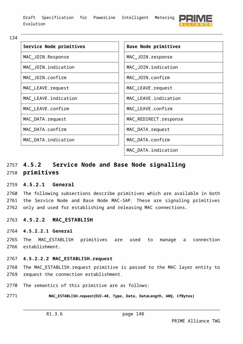
Draft Specification for PowerLine Intelligent Metering Evolution
Figure 85 – Deallocation of channel to one device results in the change of CFP allocated to another
4.7 Automatic Repeat Request (ARQ)
4.7.1 GeneralDevices complying with this specification may either implement an ARQ scheme as described in this section or no ARQ at all. This specification provides for low-cost Switch and Terminal devices that choose not to implement any ARQ mechanism at all.
4.7.2 Initial negotiationARQ is a connection property. During the initial connection negotiation, the originating device indicates its preference for ARQ or non-ARQ in CON.ARQ field. The responding device at the other end can indicate its acceptance or rejection of the ARQ in its response. If both devices agree to use ARQ for the connection, all traffic in the connection will use ARQ for acknowledgements, as described in Section 4.7.3. If the responding device rejects the ARQ in its response, the data flowing through this connection will not use ARQ.
4.7.3 ARQ mechanism
4.7.3.1 General
The ARQ mechanism works between directly connected peers (original source and final destination), as long as both of them support ARQ implementation. This implies that even for a connection between the Base Node and a Terminal (connected via one or more intermediate Switch devices), ARQ works on an end-to-end basis. The behavior of Switch Nodes in an ARQ-enabled connection is described in Section 4.7.4. When using ARQ, a unique packet identifier is associated with each packet, to aid in acknowledgement. The packet identifier is 6 bits long and can therefore denote 64 distinct packets. ARQ windowing is supported, with a maximum window size of 32 (5 bits), as described in Section 4.7.3.3.
4.7.3.2 ARQ PDU
4.7.3.2.1 General
The ARQ subheader is placed inside the data packets, after the packet header and before the ORIGINAL packet payload:
Figure 86 - MAC Data PDU with ARQ subheader
R1.3.6 page 148 PRIME Alliance TWG
136
29762977
2978
2979
298029812982
2983
298429852986298729882989
2990
2991
2992299329942995299629972998
2999
3000
30013002
30033004

Draft Specification for PowerLine Intelligent Metering Evolution
For an ARQ PDU, the PKT.LEN field in the packet header will be set as the ARQ subheader length plus the original packet payload length. By doing this, the intermediate switching Node can correctly parse the whole PDU length without the knowledge that this PDU is ARQ-enabled, so that it can transparently relaying the ARQ PDU based on the addressing information alone.
The ARQ subheader contains a set of bytes, each byte containing different subfields. The most significant bit of each byte, the M bit, indicates if there are more bytes in the ARQ subheader.
Figure 87 - ARQ subheader only with the packet id
Figure 87 shows an ARQ subheader with the first M bit of 0 and so the subheader is a single byte and contains only the packet ID for the transmitted packet.
Figure 88 - ARQ subheader with ARQ.INFO
Figure 88 has the M bit in the first byte of the ARQ subheader set, and so the subheader contains multiple bytes. The first byte contains the packet ID of the transmitted packet and then follows the ARQ.INFO which is a list of one or more bytes, where each byte could have one of the following meanings:
Figure 89 - ARQ.ACK byte fields
Figure 90 - ARQ.WIN byte fields
Figure 91 - ARQ.NACK byte fields
If there are multiple packets lost, an ARQ.NACK is sent for each of them, from the first packet lost to the last packet lost. When there are several ARQ.NACK they implicitly acknowledge the packets before the first ARQ.NACK, and the packets in between the ARQ.NACKs. If an ARQ.ACK is present, it must be placed at the end of the ARQ subheader, and should reference to an ARQ.ACKID that is later than any other ARQ.NACKID, if present. If there is at least an ARQ.NACK and an ARQ.ACK they also implicitly acknowledge any packet in the middle between the last ARQ.NACKID and the ARQ.ACK.
For interoperability, a device should be able to receive any well-formed ARQ subheader and should process at least the first ARQ.ACK or ARQ.NACK field.
The subfields have the following meanings as described in Table 51
Table 51 - ARQ fields
R1.3.6 page 149 PRIME Alliance TWG
1373005300630073008
30093010
30113012
30133014
3015
30163017
301830193020
30213022
30233024
30253026
302730283029303030313032
30333034
3035
3036

Draft Specification for PowerLine Intelligent Metering Evolution
Field Description
ARQ.FLUSH ARQ.FLUSH = 1 If an ACK must be sent immediately.
ARQ.FLUSH = 0 If an ACK is not needed.
ARQ.PKTID The id of the current packet, if the packet is empty (with no data) this is the id of the packet that will be sent next.
ARQ.ACKID The identifier with the next packet expected to be received.
ARQ.WINSIZE The window size available from the last acknowledged packet. After a connection is established its window is 1.
ARQ.NACKID Ids of the packets that need to be retransmitted.
4.7.3.2.2 ARQ subheader example
Figure 92 - Example of an ARQ subheader with all the fields present
In this example all the ARQ subheader fields are present. To make it understandable, since both Nodes are both transmitters and receivers, the side receiving this header will be called A and the other side transmitting B. The message has the packet ID of 23 if it contains data; otherwise the next data packet to be sent has the packet ID of 23. Since the flush bit is set it needs to be ACKed/NACKed.
B requests the retransmission of packets 45, 47, 48, 52, 55, 56 and 57. ACK = 60, so it has received packets <45, 46, 49, 50, 51, 53, 54, 58 and 59.
The window is 16 and it has received and processed up to packet 44 (first NACK = 45), so A can send all packets <= 60; that is, as well as sending the requested retransmits, it can also send packet ID = 60.
4.7.3.3 Windowing
A new connection between two peer devices starts with an implicit initial receiver window size of 1 and a packet identifier 0. This window size is a limiting case and the transaction (to start with) would behave like a “Stop and Wait” ARQ mechanism.
On receipt of an ARQ.WIN, the sender would adapt its window size to ARQ.WINSIZE. This buffer size is counted from the first packet completely ACK-ed, so if there is a NACK list and then an ACK the window size defines the number of packets from the first NACK-ed packet that could be sent. If there is just an ACK in the packet (without any NACK) the window size determines the number of packets that can be sent from that ACK.
R1.3.6 page 150 PRIME Alliance TWG
138
3037
30383039
3040304130423043
30443045
30463047
3048
304930503051
30523053305430553056

Draft Specification for PowerLine Intelligent Metering Evolution
An ARQ.WINSIZE value of 0 may be transmitted back by the receiver to indicate congestion at its end. In such cases, the transmitting end should wait for at least ARQCongClrTime before re-transmitting its data.
4.7.3.4 Flow control
The transmitter must manage the ACK sending algorithm by the flush bit; it is up to it having a proper ARQ communication. The receiver is only forced to send ACKs when the transmitter has sent a packet with the flush bit set, although the receiver could send more ACKs even if not forced to do it, because the flow control is only a responsibility of the transmitter.
These are the requisites to be interoperable, but the algorithm is up to the manufacturer. It is strongly recommended to piggyback data-ACK information in outgoing packets, to avoid the transmission of unnecessary packets just for ACK-ing.
4.7.3.5 Algorithm recommendation
No normative algorithm is specified, for a recommendation see Annex I.
4.7.3.6 Usage of ARQ in resource limited devices
Resource limited devices may have a low memory and simple implementation of ARQ. They may want to use a window of 1 packet. They will work as a “Stop and Wait” mechanism.
The ARQ subheader to be generated may be one of the followings:
If there is nothing to acknowledge:
Figure 93 - Stop and wait ARQ subheader with only packet ID
If there is something to acknowledge carrying data:
Figure 94 - Stop and wait ARQ subheader with an ACK
If there is something to acknowledge but without any data in the packet:
Figure 95 - Stop and wait ARQ subheader without data and with an ACK
The ARQ.WINSIZE is not generally transmitted because the window size is already 1 by default, it only may be transmitted to handle congestion and to resume the transmission again.
4.7.4 ARQ packets switchingAll Switch Nodes shall support transparent bridging of ARQ traffic, whether or not they support ARQ for their own transmission and reception. In this mode, Switch Nodes are not required to buffer the packets of the ARQ connections for retransmission.
R1.3.6 page 151 PRIME Alliance TWG
13930573058
3059
3060306130623063
306430653066
3067
3068
3069
30703071
3072
3073
30743075
3076
30773078
3079
3080
3081
30823083
3084
308530863087
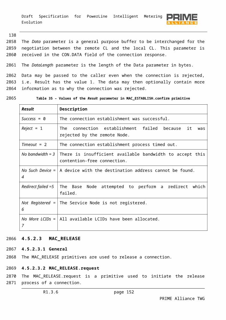
Draft Specification for PowerLine Intelligent Metering Evolution
Some Switch Nodes may buffer the packets of the ARQ connections, and perform retransmission in response to NACKs for these packets. The following general principles shall be followed.
The acknowledged packet identifiers shall have end-to-end coherency. The buffering of packets in Switch Nodes and their retransmissions shall be transparent to the
source and Destination Nodes, i.e., a Source or Destination Node shall not be required to know whether or not an intermediate Switch has buffered packets for switched data.
R1.3.6 page 152 PRIME Alliance TWG
14030883089
3090309130923093
3094
3095
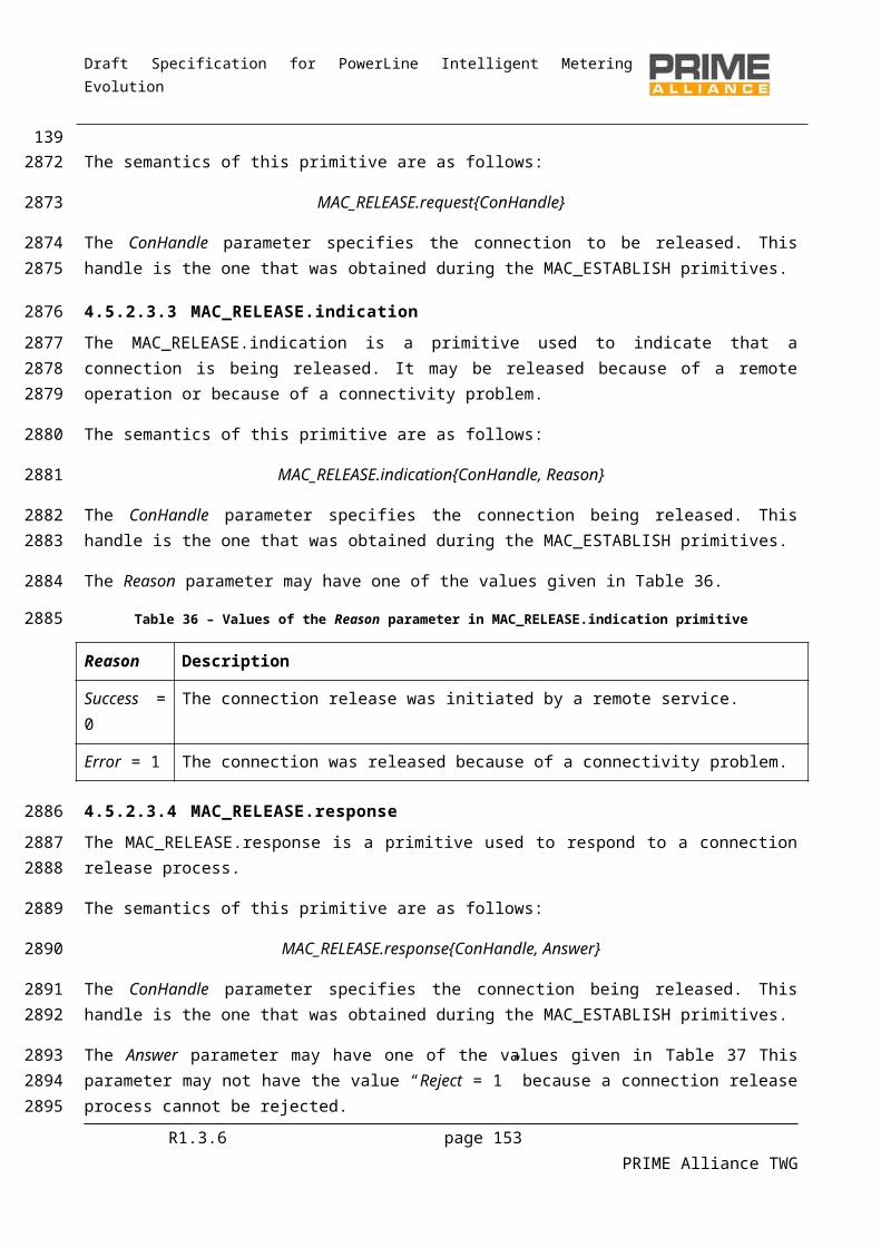
Draft Specification for PowerLine Intelligent Metering Evolution
5 Convergence layer
5.1 OverviewFigure 96 shows the overall structure of the Convergence layer.
Convergence Layer
Service Specific Convergence Sublayer (SSCS)
IPv4SSCS
IPv6SSCS
IEC - 432SSCS
NULLSSCS
“New Protocol”SSCS
Common Part Convergence Sublayer (CPCS)
Segmentation and Reassembly (SAR)
Figure 96 - Structure of the Convergence layer
The Convergence layer is separated into two sublayers. The Common Part Convergence Sublayer (CPCS) provides a set of generic services. The Service Specific Convergence Sublayer (SSCS) contains services that are specific to one communication profile. There are several SSCSs, typically one per communication profile, but only one CPCS. The use of CPCS services is optional in that a certain SSCS will use the services it needs from the CPCS, and omit services which are not needed.
5.2 Common Part Convergence Sublayer (CPCS)
5.2.1 GeneralThis specification defines only one CPCS service: Segmentation and Reassembly (SAR).
5.2.2 Segmentation and Reassembly (SAR)
5.2.2.1 General
CPCS SDUs which are larger than ‘ClMTUSize-1’ bytes are segmented at the CPCS. CPCS SDUs which are equal or smaller than ‘ClMTUSize-1’ bytes may also optionally be segmented. Segmentation means breaking up a CPCS SDU into smaller parts to be transferred by the MAC layer. At the peer CPCS, the smaller parts (segments) are put back together (i.e. reassembled) to form the complete CPCS SDU. All segments except the last segment of a segmented SDU must be the same size and at most ClMTUSize bytes in length. Segments may be decided to be smaller than ‘ClMTUSize-1’ bytes e.g. when the channel is poor. The last segment may of course be smaller than ‘ClMTUSize-1’ bytes.
In order to keep SAR functionality simple, the ClMTUSize is a constant value for all possible modulation/coding combinations at PHY layer. The value of ClMTUSize is such that with any
R1.3.6 page 153 PRIME Alliance TWG
3096
3097
3098
3099
3100
31013102310331043105
3106
3107
3108
3109
3110
3111311231133114311531163117
31183119
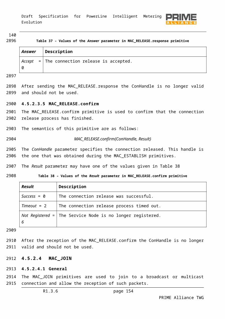
Draft Specification for PowerLine Intelligent Metering Evolution
modulation/coding combination, it is always possible to transmit a single segment in one PPDU. Therefore, there is no need for discovering a specific MTU between peer CPCSs or modifying the SAR configuration for every change in the modulation/coding combination. In order to increase efficiency, a Service Node which supports packet aggregation may combine multiple segments into one PPDU when communicating with its peer.
Segmentation always adds a 1-byte header to each segment. The first 2 bits of SAR header identify the type of segment. The semantics of the rest of the header information then depend on the type of segment. The structure of different header types is shown in Figure 97 and individual fields are explained in
Table 52. Not all fields are present in each SAR header. Either SAR.NSEGS or SAR.SEQ is present, but not both.
Figure 97 - Segmentation and Reassembly Headers
Table 52 - SAR header fields
Name Length Description
SAR.TYPE 2 bits Type of segment. 0b00: first segment; 0b01: intermediate segment; 0b10: last segment; 0b11: reserved in this version of the specification.
SAR.NSEGS 6 bits ‘Number of Segments’ – 1.
SAR.SEQ 6 bits Sequence number of segment.
Every segment (except for the first one) includes a sequence number so that the loss of a segment could be detected in reassembly. The sequence numbering shall start from zero with every new CPCS SDU. The first segment which contains a SAR.SEQ field must have SAR.SEQ = 0. All subsequent segments from the same CPCS SDU shall increase this sequence number such that the SAR.SEQ field adds one with every transmission.
The value SAR.NSEGS indicates the total number of segments, minus one. So when SAR.NSEGS = 0, the CPCS SDU is sent in one segment. SAR.NSEGS = 63 indicates there will be 64 segments to form the full CPCS SDU. When SAR.NSEGS = 0, it indicates that this first segment is also the last segment. No further segment with SAR.TYPE = 0b01 or 0b10 is to be expected for this one-segment CPCS SDU.
SAR at the receiving end shall buffer all segments and deliver only fully reassembled CPCS SDUs to the SSCS above. Should reassembly fail due to a segment not being received or too many segments being …received etc., SAR shall not deliver any incomplete CPCS SDU to the SSCS above.
R1.3.6 page 154 PRIME Alliance TWG
31203121312231233124
312531263127
31283129
3130
3132
3133
31343135313631373138
3139314031413142
314331443145

Draft Specification for PowerLine Intelligent Metering Evolution
5.2.2.2 SAR constants
Table 53 shows the constants for the SAR service.
Table 53 - SAR Constants
Constant Value
ClMTUSize 256 Bytes.
ClMaxAppPktSize Max Value (SAR.NSEGS) x ClMTUSize.
5.3 NULL Service-Specific Convergence Sublayer (NULL SSCS)
5.3.1 OverviewNull SSCS provides the MAC layer with a transparent path to upper layers, being as simple as possible and minimizing overhead. It is intended for applications that do not need any special convergence capability.
The unicast and multicast connections of this SSCS shall use the SAR service, as defined in 5.2.2. If they do not need the SAR service they shall still include the SAR header (notifying just one segment).
The CON.TYPE and MUL.TYPE (see Annex E) for unicast connections and multicast groups shall use the same type that has been already defined for the application that makes use of this Null SSCS.
5.3.2 PrimitivesNull SSCS primitives are just a direct mapping of the MAC primitives. A full description of every primitive is avoided, because the mapping is direct and they will work as the ones of the MAC layer.
The directly mapped primitives have exactly the same parameters as the ones in the MAC layer and perform the same functionality. The set of primitives that are directly mapped are shown below.
Table 54 - Primitive mapping between the Null SSCS primitives and the MAC layer primitives
Null SSCS mapped to … … a MAC primitiveCL_NULL_ESTABLISH.request MAC_ESTABLISH.requestCL_NULL_ESTABLISH.indication MAC_ESTABLISH.indicationCL_NULL_ESTABLISH.response MAC_ESTABLISH.responseCL_NULL_ESTABLISH.confirm MAC_ESTABLISH.confirmCL_NULL_RELEASE.request MAC_RELEASE.requestCL_NULL_RELEASE.indication MAC_RELEASE.indicationCL_NULL_RELEASE.response MAC_RELEASE.responseCL_NULL_RELEASE.confirm MAC_RELEASE.confirmCL_NULL_JOIN.request MAC_JOIN.requestCL_NULL_JOIN.indication MAC_JOIN.indicationCL_NULL_JOIN.response MAC_JOIN.responseCL_NULL_JOIN.confirm MAC_JOIN.confirm
R1.3.6 page 155 PRIME Alliance TWG
3146
3147
3148
3149
3150
31513152
31533154
31553156
3157
31583159
31603161
3162
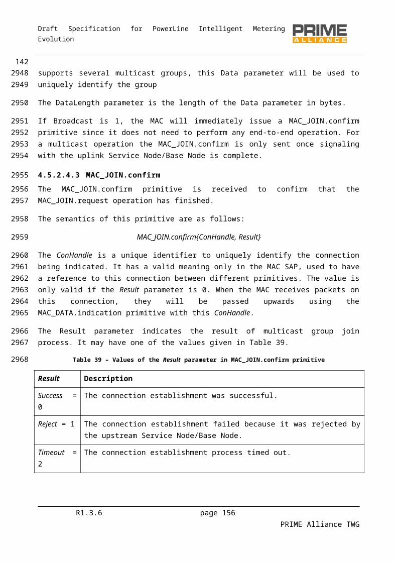
Draft Specification for PowerLine Intelligent Metering Evolution
Null SSCS mapped to … … a MAC primitiveCL_NULL_LEAVE.request MAC_LEAVE.requestCL_NULL_LEAVE.indication MAC_LEAVE.indicationCL_NULL_LEAVE.response MAC_LEAVE.responseCL_NULL_LEAVE.confirm MAC_LEAVE.confirmCL_NULL_DATA.request MAC_DATA.requestCL_NULL_DATA.indication MAC_DATA.indicationCL_NULL_DATA.confirm MAC_DATA.confirmCL_NULL_SEND.request MAC_SEND.requestCL_NULL_SEND.indication MAC_SEND.indicationCL_NULL_SEND.confirm MAC_SEND.confirm
5.4 IPv4 Service-Specific Convergence Sublayer (IPv4 SSCS)
5.4.1 OverviewThe IPv4 SSCS provides an efficient method for transferring IPv4 packets over the OFDM PRIME Subnetworks. Several conventions do apply:
A Service Node can send IPv4 packets to the Base Node or to other Service Nodes. It is assumed that the Base Node acts as a router between the OFDM PRIME Subnetwork and any
other network. The Base Node could also act as a NAT. How the Base Node connects to the other networks is beyond the scope of this specification.
In order to keep implementations simple, only one single route is supported per local IPv4 address. Service Nodes may use statically configured IPv4 addresses or DHCP to obtain IPv4 addresses. The Base Node performs IPv4 to EUI-48 address resolution. Each Service Node registers its IPv4
address and EUI-48 address with the Base Node (see section 5.4.2). Other Service Nodes can then query the Base Node to resolve an IPv4 address into a EUI-48 address. This requires the establishment of a dedicated connection with the Base Node for address resolution.
The IPv4 SSCS performs the routing of IPv4 packets. In other words, the IPv4 SSCS will decide whether the packet should be sent directly to another Service Node or forwarded to the configured gateway.
Although IPv4 is a connectionless protocol, the IPv4 SSCS is connection-oriented. Once address resolution has been performed, a connection is established between the source and destination Service Node for the transfer of IPv4 packets. This connection is maintained while traffic is being transferred and may be closed after a period of inactivity.
The CPCS (see section 5.2) SAR sublayer shall always be present with the IPv4 Convergence layer. Generated MSDUs are at most ‘ClMTUSize’ bytes long and upper layer PDU messages are not expected must not to be longer than ClMaxAppPktSize.
Optionally TCP/IPv4 headers may be compressed. Compression is negotiated as part of the connection establishment phase.
The broadcasting of IPv4 packets is supported using the MAC broadcast mechanism. The multicasting of IPv4 packets is supported using the MAC multicast mechanism.
R1.3.6 page 156 PRIME Alliance TWG
3163
3164
3165
31663167
316831693170317131723173317431753176317731783179318031813182318331843185318631873188318931903191
Draft Specification for PowerLine Intelligent Metering Evolution
The IPv4 SSCS has a number of connection types. For address resolution there is a connection to the Base Node. For IPv4 data transfer there is one connection per Destination Node: with the Base Node that acts as the IPv4 gateway to other networks or to/with any other Node in the same Subnetwork. This is shown in Figure 98.
IPv4 SSCS address resolution connection
IPv4 SSCS data transfer connection
Figure 98 - IPv4 SSCS connection example
Here, Nodes B, E and F have address resolution connections to the Base Node. Node E has a data connection to the Base Node and Node F. Node F is also has a data connection to Node B. The figure does not show broadcast and multicast connections.
5.4.2 Address resolution
5.4.2.1 General
The IPv4 layer will present the IPV4 SSCS with an IPv4 packet to be transferred. The IPV4 SSCS is responsible for determining which Service Node the packet should be delivered to using the IPv4 addresses in the packet. The IPV4 SSCS must then establish a connection to the destination if one does not already exist so that the packet can be transferred. Three classes of IPv4 addresses can be used and the following subsections describe how these addresses are resolved into EUI-48 addresses.
5.4.2.2 Unicast addresses
5.4.2.2.1 General
IPv4 unicast addresses must be resolved into unicast EUI-48 addresses. The Base Node maintains a database of IPv4 addresses and EUI-48 addresses. Address resolution then operates by querying this database. A Service Node must establish a connection to the address resolution service running on the Base Node, using the connection type value TYPE (see Annex E) TYPE_CL_IPv4_AR. No data should be passed in the connection establishment. Using this connection, the Service Node can use two mechanisms as defined in the following paragraphs.
R1.3.6 page 157 PRIME Alliance TWG
3192319331943195
3196
3197
319831993200
3201
3202
32033204320532063207
3208
3209
321032113212321332143215
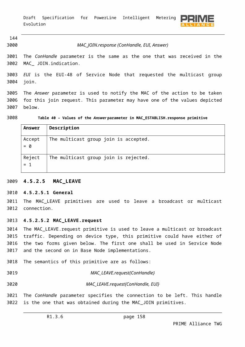
Draft Specification for PowerLine Intelligent Metering Evolution
5.4.2.2.2 Address registration and unregistration
A Service Node uses the AR_REGISTER_S message to register an IPv4 address and the corresponding EUI-48 address meaning request from the base node to record inside its registration table, the IPv4 address and its corresponding service node EUI-48. The Base Node will acknowledge an AR_REGISTER_B message. The Service Node may register multiple IPv4 addresses for the same EUI-48 address.
A Service Node uses the AR_DEREGISTER_S message to unregister an IPv4 address and the corresponding EUI-48 address meaning requests from the base node to delete inside its registration table, the entry corresponding to the concerned IPv4 address. The Base Node will acknowledge it with an AR_DEREGISTER_B message.
When the IPv4 address resolution connection between the Service Node and the Base Node is closed, the Base Node should remove all addresses associated to that connection.
5.4.2.2.3 Address lookup
A Service Node uses the AR_LOOKUP_S message to perform a lookup. The message contains the IPv4 address to be resolved. The Base Node will respond with an AR_LOOKUP_B message that contains an error code and, if there is no error, the EUI-48 address associated with the IPv4 address. If the Base Node has multiple entries in its database for the same IPv4 address, the possible returned EUI-48 address is undefined.
5.4.2.3 Broadcast Address
IPv4 broadcast address 255.255.255.255 maps to a MAC broadcast connection with LCID equal to LCI_CL_IPv4_BROADCAST. All IPv4 broadcast packets will be sent to this connection. When an IPv4 broadcast packet is received on this connection, the IPv4 address should be examined to determine if it is a broadcast packet for the Subnetwork in which the Node has an IPv4 address. Only broadcast packets from member subnets should be passed up the IPv4 protocol stack.
5.4.2.4 Multicast Addresses
Multicast IPv4 addresses are mapped to a OFDM PRIME MAC multicast connection by the Base Node using an address resolution protocol.
To join a multicast group, AR_MCAST_REG_S is sent from the Service Node to the Base Node with the IPv4 multicast address. The Base Node will reply with an AR_MCAST_REG_B that contains the LCID value assigned to the said multicast address. However, the Base Node may also allocate other LCIDs which are not in use if it so wishes. The Service Node can then join a multicast group (see 4.6.7.2) for the given LCID to receive IPv4 multicast packets. These LCID values can be reused so that multiple IPv4 destination multicast addresses can be seen on the same LCID. To leave the multicast group, AR_MCAST_UNREG_S is sent from the Service Node to the Base Node with the IPv4 multicast address. The Base Node will acknowledge it with an AR_MCAST_UNREG_B message.
When a Service Node wants to send an IPv4 multicast datagram, it just uses the appropriate LCID. If the Service Node has not joined the multicast group, it needs first to learn the LCID to be used. The process with AR_MCAST_REG_S|B messages as described above can be used. While IPv4 multicast packets are still
being sent, the Service Node remains registered to the multicast group. Tmcast_reg after the last IPv4
R1.3.6 page 158 PRIME Alliance TWG
3216
3217321832193220
3221322232233224
32253226
3227
32283229323032313232
3233
32343235323632373238
3239
32403241
32423243324432453246324732483249
325032513252
3253
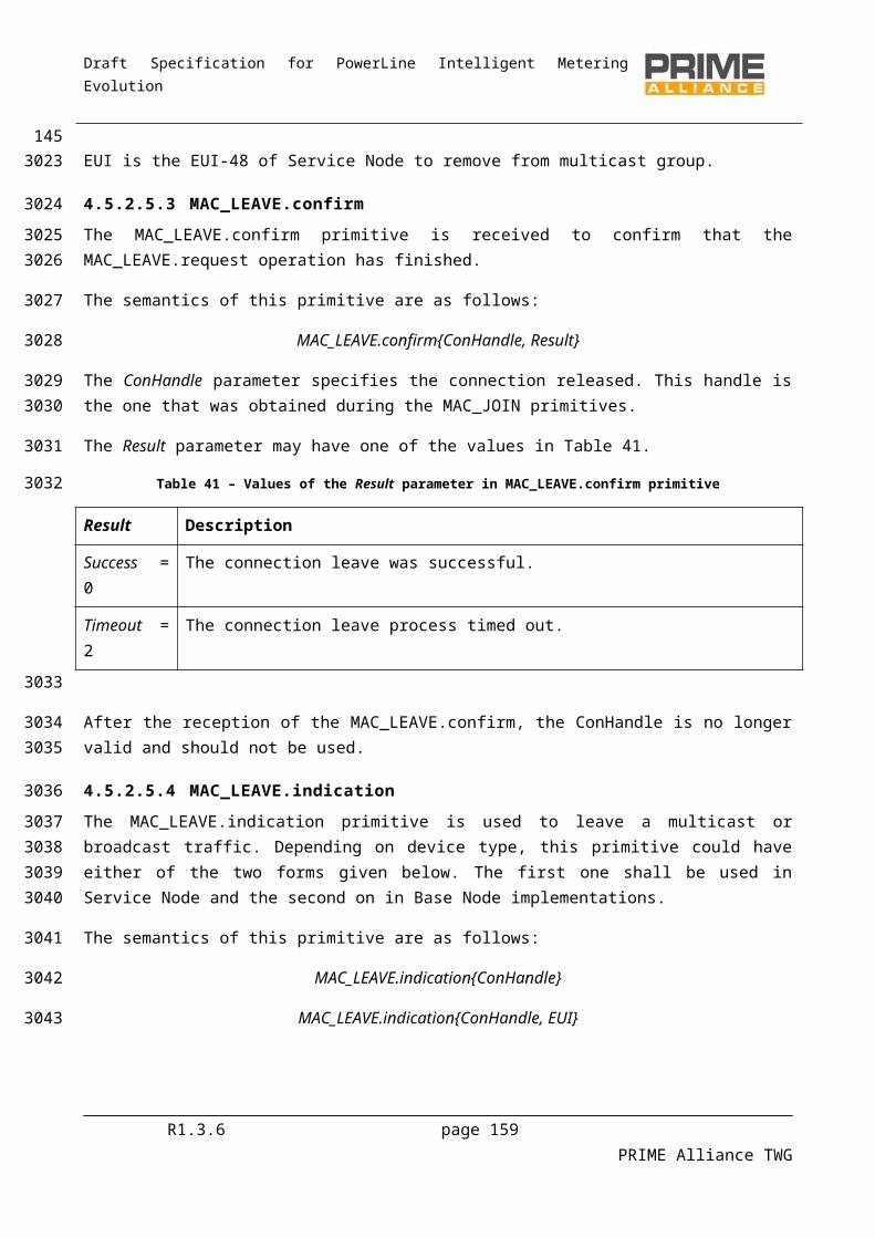
Draft Specification for PowerLine Intelligent Metering Evolution
multicast datagram was sent, the Service Node should unregister from the multicast group, by means of
AR_MCAST_UNREG_S|B messages. The nominal value of Tmcast_reg is 10 minutes; however, other values may be used.
5.4.2.5 Retransmission of address resolution packets
The connection between the Service Node and the Base Node for address resolution is not reliable if the MAC ARQ is not used. The Service Node is responsible for making retransmissions if the Base Node does not respond in one second. It is not considered an error when the Base Node receives the same registration requests multiple times or is asked to remove a registration that does not exist. These conditions can be the result of retransmissions.
5.4.3 IPv4 packet transferFor packets to be transferred, a connection needs to be established between source and Destination Nodes. The IPV4 SSCS will examine each IPv4 packet to determine the destination EUI-48 address. If a data connection to the destination already exists, the packet is sent. To establish this, IPv4 SSCS keeps a table for each connection, with information shown in Table 55 (see RFC 1144).. To use this table, it is first necessary to determine if the IPv4 destination address is in the local Subnetwork or if a gateway has to be used. The netmask associated with the local IPv4 address is used to determine this. If the IPv4 destination address is not in the local Subnetwork, the address of the default gateway is used instead of the destination address when the table is searched.
Table 55 - IPV4 SSCS Table Entry
Parameter Description
CL_IPv4_Con.Remote_IP Remote IPv4 address of this connection.
CL_IPv4_Con.ConHandle MAC Connection handle for the connection.
CL_IPv4_Con.LastUsed Timestamp of last packet received/transmitted .
CL_IPv4_Con.HC Header Compression scheme being used.
CL_IPv4_CON.RxSeq Next expected Receive sequence number.
CL_IPv4_CON.TxSeq Sequence number for next transmission.
The IPV4 SSCS may close a connection when it has not been used for an implementation-defined time period. When the connection is closed the entry for the connection is removed at both ends of the connection.
When a connection to the destination does not exist, more work is necessary. The address resolution service is used to determine the EUI-48 address of the remote IPv4 address if it is local or the gateway associated with the local address if the destination address is in another Subnetwork. When the Base Node replies with the EUI-48 address of the destination Service Node, a MAC connection is established to the remote device. The TYPE value of this connection is TYPE_CL_IPv4_UNICAST. The data passed in the request message is defined in section 5.4.7.4. The local IPv4 address is provided so that the remote device can add
R1.3.6 page 159 PRIME Alliance TWG
3254
32553256
3257
32583259326032613262
3263
32643265326632673268326932703271
3272
327332743275
327632773278327932803281
Draft Specification for PowerLine Intelligent Metering Evolution
the new connection to its cache of connections for sending data in the opposite direction. The use of Van Jacobson Header Compression is also negotiated as part of the connection establishment. Once the connection has been established, the IPv4 packet can be sent.
When the packet is addressed to the IPv4 broadcast address, the packet has to be sent using the MAC broadcast service. When the IPV4 SSCS is opened, a broadcast connection is established for transferring all broadcast packets. The broadcast IPv4 packet is simply sent to this connection. Any packet received on this broadcast connection is passed to the IPv4 protocol stack.
5.4.4 Segmentation and reassemblyThe IPV4 SSCS should support IPv4 packets with an MTU of 1500 bytes. This requires the use of SAR (see 5.2.2).
5.4.5 Header compressionVan Jacobson TCP/IP Header Compression is an optional feature in the IPv4 SSCS. The use of VJ compression is negotiated as part of the connection establishment phase of the connection between two Service Nodes.
VJ compression is designed for use over a point-to-point link layer that can inform the decompressor when packets have been corrupted or lost. When there are errors or lost packets, the decompressor can then resynchronize with the compressor. Without this resynchronization process, erroneous packets will be produced and passed up the IPv4 stack.
The MAC layer does not provide the facility of detecting lost packets or reporting corrupt packets. Thus, it is necessary to add this functionality in the IPV4 SSCS. The IPV4 SSCS maintains two sequence numbers when VJ compression is enabled for a connection. These sequence numbers are 8 bits in size. When transmitting an IPv4 packet, the CL_IPv4_CON.TxSeq sequence number is placed in the packet header, as shown in Section 5.4.3. The sequence number is then incremented. Upon reception of a packet, the sequence number in the received packet is compared against CL_IPv4_CON.RxSeq. If they differ, TYPE_ERROR, as defined in RFC1144, is passed to the decompressor. The CL_IPv4_CON.RxSeq value is always updated to the value received in the packet header.
Header compression should never be negotiated for broadcast or multicast packets.
5.4.6 Quality of Service mappingThe OFDM PRIME MAC specifies that the contention-based access mechanism supports 4 priority levels (1-4). Level 1 is used for MAC signaling messages, but not exclusively so.
IPv4 packets include a TOS field in the header to indicate the QoS the packet would like to receive. Three bits of the TOS indicate the IP Precedence. The following table specifies how the IP Precedence is mapped into the OFDM PRIME MAC priority.
Table 56 - Mapping IPv4 Precedence to OFDM PRIME MAC priority
IP Precedence MAC Priority
R1.3.6 page 160 PRIME Alliance TWG
328232833284
3285328632873288
3289
32903291
3292
329332943295
3296329732983299
33003301330233033304330533063307
3308
3309
33103311
331233133314
3315
Draft Specification for PowerLine Intelligent Metering Evolution
000 – Routine 4
001 – Priority 4
010 – Immediate 3
011 – Flash 3
100 – Flash Override 2
101 – Critical 2
110 – Internetwork Control 1
111 – Network Control 1
Note: At the MAC layer level the priority as stated in the Packet header field is the value assigned in this table minus 1, as the range of PKT.PRIO field is from 0 to 3.
5.4.7 Packet formats and connection data
5.4.7.1 General
This section defines the format of IPV4 SSCS PDUs.
5.4.7.2 Address resolution PDUs
5.4.7.2.1 General
The following PDUs are transferred over the address resolution connection between the Service Node and the Base Node. The following sections define AR.MSG values in the range of 0 to 11. All higher values are reserved for later versions of this specification.
5.4.7.2.2 AR_REGISTER_S
Table 57 shows the address resolution register message sent from the Service Node to the Base Node.
Table 57 - AR_REGISTER_S message format
Name Length Description
AR.MSG 8-bits Address Resolution Message Type.
For AR_REGISTER_S = 0.
AR.IPv4 32-bits IPv4 address to be registered.
AR.EUI-48 48-bits EUI-48 to be registered.
R1.3.6 page 161 PRIME Alliance TWG
3316
33173318
3319
3320
3321
3322
3323
332433253326
3327
3328
3329
Draft Specification for PowerLine Intelligent Metering Evolution
5.4.7.2.3 AR_REGISTER_B
Table 58 shows the address resolution register acknowledgment message sent from the Base Node to the Service Node.
Table 58 - AR_REGISTER_B message format
Name Length Description
AR.MSG 8-bits Address Resolution Message Type.
For AR_REGISTER_B = 1.
AR.IPv4 32-bits Registered IPv4 address.
AR.EUI-48 48-bits EUI-48 registered.
The AR.IPv4 and AR.EUI-48 fields are included in the AR_REGISTER_B message so that the Service Node can perform multiple overlapping registrations.
5.4.7.2.4 AR_UNREGISTER_S
Table 59 shows the address resolution unregister message sent from the Service Node to the Base Node.
Table 59 - AR_UNREGISTER_S message format
Name Length Description
AR.MSG 8-bits Address Resolution Message Type.
For AR_UNREGISTER_S = 2.
AR.IPv4 32-bits IPv4 address to be unregistered.
AR.EUI-48 48-bits EUI-48 to be unregistered.
5.4.7.2.5 AR_UNREGISTER_B
Table 60 shows the address resolution unregister acknowledgment message sent from the Base Node to the Service Node.
Table 60 - AR_UNREGISTER_B message format
Name Length Description
AR.MSG 8-bits Address Resolution Message Type.
For AR_UNREGISTER_B = 3.
AR.IPv4 32-bits Unregistered IPv4 address .
AR.EUI-48 48-bits Unregistered EUI-48.
R1.3.6 page 162 PRIME Alliance TWG
3330
33313332
3333
3334
33353336
3337
3338
3339
3340
33413342
3343
Draft Specification for PowerLine Intelligent Metering Evolution
The AR.IPv4 and AR.EUI-48 fields are included in the AR_UNREGISTER_B message so that the Service Node can perform multiple overlapping Unregistrations.
5.4.7.2.6 AR_LOOKUP_S
Table 61 shows the address resolution lookup message sent from the Service Node to the Base Node.
Table 61 - AR_LOOKUP_S message format
Name Length Description
AR.MSG 8-bits Address Resolution Message Type.
For AR_LOOKUP_S = 4.
AR.IPv4 32-bits IPv4 address to lookup.
5.4.7.2.7 AR_LOOKUP_B
Table 62 shows the address resolution lookup response message sent from the Base Node to the Service Node.
Table 62 - AR_LOOKUP_B message format
Name Length Description
AR.MSG 8-bits Address Resolution Message Type.
For AR_LOOKUP_B = 5.
AR.IPv4 32-bits IPv4 address looked up.
AR.EUI-48 48-bits EUI-48 for IPv4 address.
AR.Status 8-bits Lookup status, indicating if the address was found or an error occurred.
0 = found, AR.EUI-48 valid; 1 = unknown, AR.EUI-48 undefined.
The lookup may fail if the requested address has not been registered. In that case, AR.Status will have a value other than zero and the contents of AR.EUI-48 will be undefined. The lookup is only successful when AR.Status is zero. In that case, the EUI-48 field contains the resolved address.
5.4.7.2.8 AR_MCAST_REG_S
Table 63 shows the multicast address resolution register message sent from the Service Node to the Base Node.
Table 63 - AR_MCAST_REG_S message format
Name Length Description
R1.3.6 page 163 PRIME Alliance TWG
33443345
3346
3347
3348
3349
33503351
3352
335333543355
3356
33573358
3359

Draft Specification for PowerLine Intelligent Metering Evolution
AR.MSG 8-bits Address Resolution Message Type.
For AR_MCAST_REG_S = 8.
AR.IPv4 32-bits IPv4 multicast address to be registered.
5.4.7.2.9 AR_MCAST_REG_B
Table 64 shows the multicast address resolution register acknowledgment message sent from the Base Node to the Service Node.
Table 64 - AR_MCAST_REG_B message format
Name Length Description
AR.MSG 8-bits Address Resolution Message Type.
For AR_MCAST_REG_B = 9.
AR.IPv4 32-bits IPv4 multicast address registered.
Reserved 2-bits Reserved. Should be encoded as 0.
AR.LCID 6-bits LCID assigned to this IPv4 multicast address.
The AR.IPv4 field is included in the AR_MCAST_REG_B message so that the Service Node can perform multiple overlapping registrations.
5.4.7.2.10 AR_MCAST_UNREG_S
Table 65 shows the multicast address resolution unregister message sent from the Service Node to the Base Node.
Table 65 - AR_MCAST_UNREG_S message format
Name Length Description
AR.MSG 8-bits Address Resolution Message Type.
For AR_MCAST_UNREG_S = 10.
AR.IPv4 32-bits IPv4 multicast address to be unregistered.
5.4.7.2.11 AR_MCAST_UNREG_B
Table 66 shows the multicast address resolution unregister acknowledgment message sent from the Base Node to the Service Node.
Table 66 - AR_MCAST_UNREG_B message format
Name Length Description
R1.3.6 page 164 PRIME Alliance TWG
3360
33613362
3363
3364
33653366
3367
33683369
3370
3371
33723373
3374

Draft Specification for PowerLine Intelligent Metering Evolution
AR.MSG 8-bits Address Resolution Message Type.
For AR_MCAST_UNREG_B = 11;
AR.IPv4 32-bits IPv4 multicast address unregistered.
The AR.IPv4 field is included in the AR_MCAST_UNREG_B message so that the Service Node can perform multiple overlapping Unregistrations.
5.4.7.3 IPv4 packet format
5.4.7.3.1 General
The following PDU formats are used for transferring IPv4 packets between Service Nodes. Two formats are defined. The first format is for when header compression is not used. The second format is for Van Jacobson Header Compression.
5.4.7.3.2 IPv4 Packet Format, No Negotiated Header Compression
When no header compression has been negotiated, the IPv4 packet is simply sent as is, without any header.
Table 67 - IPv4 Packet format without negotiated header compression
Name Length Description
IPv4.PKT n-octets The IPv4 Packet.
5.4.7.3.3 IPv4 Packet Format with VJ Header Compression
With Van Jacobsen header compression, a one-octet header is needed before the IPv4 packet.
Table 68 - IPv4 Packet format with VJ header compression negotiated
Name Length Description
IPv4.Type 2-bits Type of compressed packet.
IPv4.Type = 0 – TYPE_IP; IPv4.Type = 1 – UNCOMPRESSED_TCP; IPv4.Type = 2 – COMPRESSED_TCP; IPv4.Type = 3 – TYPE_ERROR.
IPv4.Seq 6-bits Packet sequence number.
IPv4.PKT n-octets The IPv4 Packet.
R1.3.6 page 165 PRIME Alliance TWG
3375
33763377
3378
3379
338033813382
3383
3384
3385
3386
3387
3388
3389

Draft Specification for PowerLine Intelligent Metering Evolution
The IPv4.Type value TYPE_ERROR is never sent. It is a pseudo packet type used to tell the decompressor that a packet has been lost.
5.4.7.4 Connection Data
5.4.7.4.1 General
When a connection is established between Service Nodes for the transfer of IPv4 packets, data is also transferred in the connection request packets. This data allows the negotiation of compression and notification of the IPv4 address.
5.4.7.4.2 Connection Data from the Initiator
Table 69 shows the connection data sent by the initiator.
Table 69 - Connection signalling data sent by the initiator
Name Length Description
Reserved 6-bits Should be encoded as 0 in this version of the IPV4 SSCS protocol.
Data.HC 2-bit Header Compression .
Data.HC = 0 – No compression requested; Data.HC = 1 – VJ Compression requested; Data.HC = 2, 3 – Reserved for future versions of the specification.
Data.IPv4 32-bits IPv4 address of the initiator
If the device accepts the connection, it should copy the Data.IPv4 address into a new table entry along with the negotiated Data.HC value.
5.4.7.4.3 Connection Data from the Responder
Table 70 shows the connection data sent in response to the connection request.
Table 70 - Connection signaling data sent by the responder
Name Length Description
Reserved 6-bits Should be encoded as zero in this version of the IPV4 SSCS protocol.
Data.HC 2-bit Header Compression negotiated.
Data.HC = 0 – No compression permitted; Data.HC = 1 – VJ Compression negotiated; Data.HC = 2,3 – Reserved.
A header compression scheme can only be used when it is supported by both Service Nodes. The responder may only set Data.HC to 0 or the same value as that received from the initiator. When the same value is used, it indicates that the requested compression scheme has been negotiated and will be used for the R1.3.6 page 166 PRIME Alliance TWG
33903391
3392
3393
339433953396
3397
3398
3399
34003401
3402
3403
3404
3405
340634073408

Draft Specification for PowerLine Intelligent Metering Evolution
connection. Setting Data.HC to 0 allows the responder to deny the request for that header compression scheme or force the use of no header compression.
5.4.8 Service Access Point
5.4.8.1 General
This section defines the service access point used by the IPv4 layer to communicate with the IPV4 SSCS.
5.4.8.2 Opening and closing the IPv4 SSCS
5.4.8.2.1 General
The following primitives are used to open and close the IPv4 SSCS. The IPv4 SSCS may be opened once only. The IPv4 layer may close the IPv4 SSCS when the IPv4 interface is brought down. The IPv4 SSCS will also close the IPv4 SSCS when the underlying MAC connection to the Base Node has been lost.
5.4.8.2.2 CL_IPv4_ESTABLISH.request
The CL_IPv4_ESTABLISH.request primitive is passed from the IPv4 layer to the IPV4 SSCS. It is used when the IPv4 layer brings the interface up.
The semantics of this primitive are as follows:
CL_IPv4_ESTABLISH.request
On receiving this primitive, the IPV4 SSCS will form the address resolution connection to the Base Node and join the broadcast group used for receiving/transmitting broadcast packets.
5.4.8.2.3 CL_IPv4_ESTABLISH.confirm
The CL_IPv4_ESTABLISH.confirm primitive is passed from the IPV4 SSCS to the IPv4 layer. It is used to indicate that the IPv4 SSCS is ready to access IPv4 packets to be sent to peers.
The semantics of this primitive are as follows:
CL_IPv4_ESTABLISH.confirm
Once the IPv4 SSCS has established all the necessary connections and is ready to transmit and receive IPv4 packets, this primitive is passed to the IPv4 layer. If the IPV4 SSCS encounters an error while opening, it responds with a CL_IPv4_RELEASE.confirm primitive, rather than a CL_IPv4_ESTABLISH.confirm.
5.4.8.2.4 CL_IPv4_RELEASE.request
The CL_IPv4_RELEASE.request primitive is used by the IPv4 layer when the interface is put down. The IPV4 SSCS closes all connections so that no more IPv4 packets are received and all resources are released.
The semantics of this primitive are as follows:
CL_IPv4_RELEASE.request
Once the IPV4 SSCS has released all its connections and resources it returns a CL_IPv4_RELEASE.confirm.
R1.3.6 page 167 PRIME Alliance TWG
34093410
3411
3412
3413
3414
3415
341634173418
3419
34203421
3422
3423
34243425
3426
34273428
3429
3430
343134323433
3434
34353436
3437
3438
3439
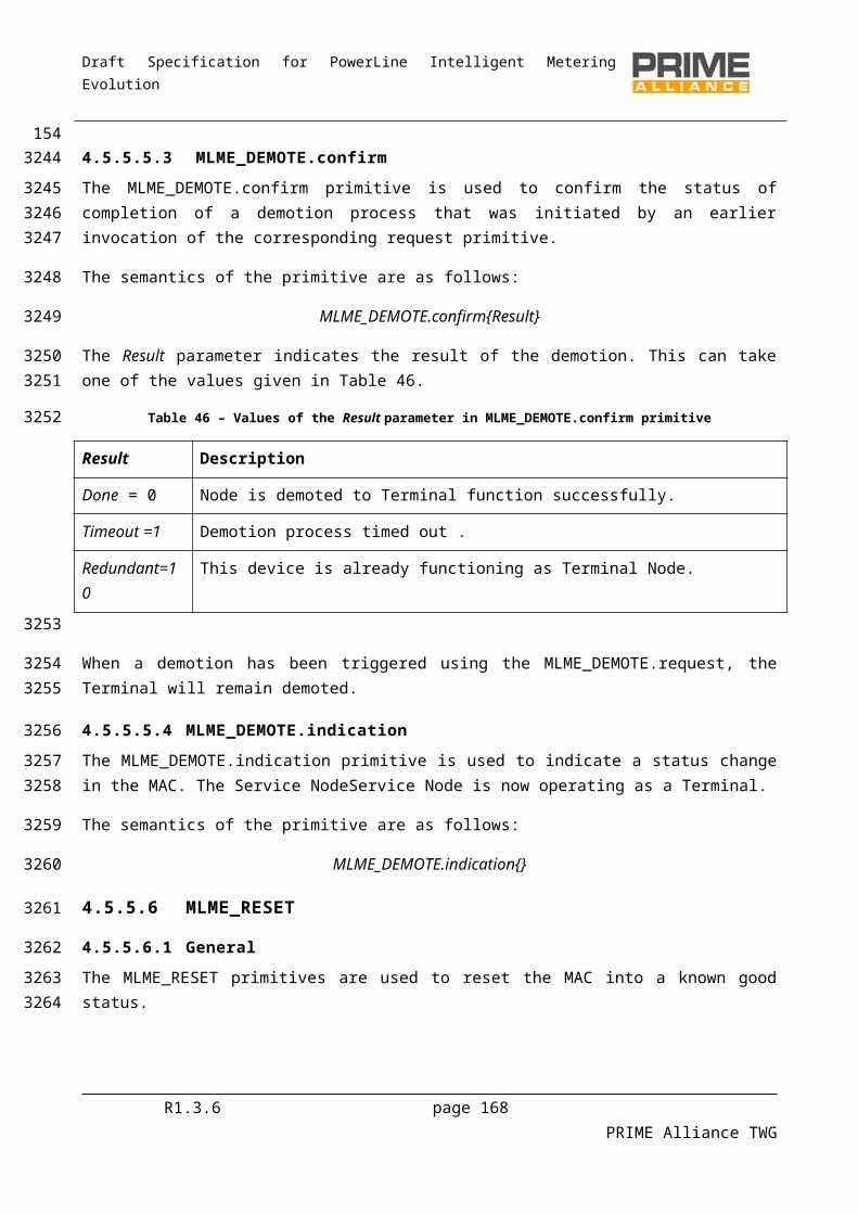
Draft Specification for PowerLine Intelligent Metering Evolution
5.4.8.2.5 CL_IPv4_RELEASE.confirm
The CL_IPv4_RELEASE.confirm primitive is used by the IPv4 SSCS to indicate to the IPv4 layer that the IPv4 SSCS has been closed. This can be as a result of a CL_IPv4_RELEASE.request primitive, a CL_IPv4_ESTABLISH.request primitive, or because the MAC layer indicates the address resolution connection has been lost, or the Service Node itself is no longer registered.
The semantics of this primitive are as follows:
CL_IPv4_RELEASE.confirmresult
The result parameter has the meanings defined in Table 134.
5.4.8.3 Unicast address management
5.4.8.3.1 General
The primitives defined here are used for address management, i.e. the registration and Unregistration of IPv4 addresses associated with this IPv4 SSCS .
When there are no IPv4 addresses associated with the IPv4 SSCS, the IPv4 SSCS will only send and receive broadcast and multicast packets; unicast packets may not be sent. However, this is sufficient for BOOTP/DHCP operation to allow the device to gain an IPv4 address. Once an IPv4 address has been registered, the IPv4 layer can transmit unicast packets that have a source address equal to one of its registered addresses.
5.4.8.3.2 CL_IPv4_REGISTER.request
This primitive is passed from the IPv4 layer to the IPv4 SSCS to register an IPv4 address.
The semantics of this primitive are as follows:
CL_IPv4_REGISTER.requestIPv4, netmask, gateway
The IPv4 address is the address to be registered.
The netmask is the network mask, used to mask the network number from the address. The netmask is used by the IPv4 SSCS to determine whether the packet should be delivered directly or the gateway should be used.
The gateway is an IPv4 address of the gateway to be used for packets with the IPv4 local address but the destination address is not in the same Subnetwork as the local address.
Once the IPv4 address has been registered to the Base Node, a CL_IPv4_REGISTER.confirm primitive is used. If the registration fails, the CL_IPv4_RELEASE.confirm primitive will be used.
5.4.8.3.3 CL_IPv4_REGISTER.confirm
This primitive is passed from the IPv4 SSCS to the IPv4 layer to indicate that a registration has been successful.
The semantics of this primitive are as follows:
R1.3.6 page 168 PRIME Alliance TWG
3440
3441344234433444
3445
3446
3447
3448
3449
34503451
34523453345434553456
3457
3458
3459
3460
3461
346234633464
34653466
34673468
3469
34703471
3472
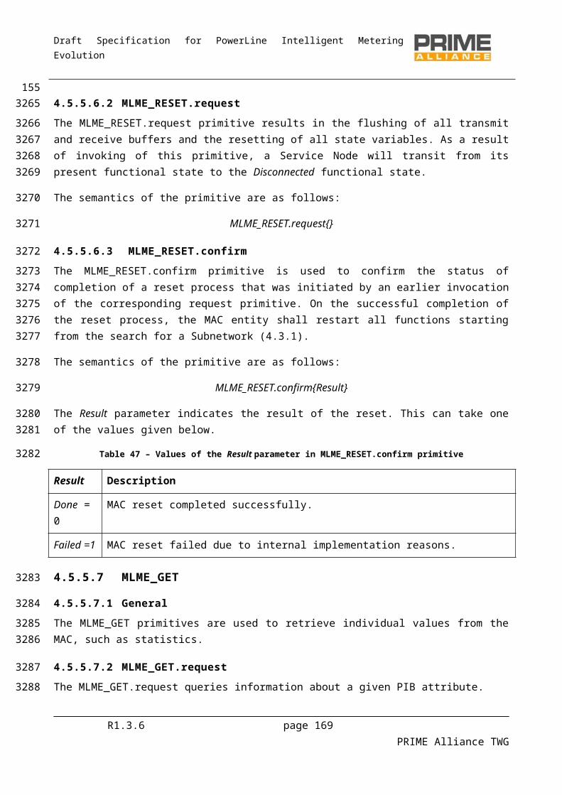
Draft Specification for PowerLine Intelligent Metering Evolution
CL_IPv4_REGISTER.confirmIPv4
The IPv4 address is the address that was registered.
Once registration has been completed, the IPv4 layer may send IPv4 packets using this source address.
5.4.8.3.4 CL_IPv4_UNREGISTER.request
This primitive is passed from the IPv4 layer to the IPv4 SSCS to unregister an IPv4 address.
The semantics of this primitive are as follows:
CL_IPv4_UNREGISTER.requestIPv4
The IPv4 address is the address to be unregistered.
Once the IPv4 address has been unregistered to the Base Node, a CL_IPv4_UNREGISTER.confirm primitive is used. If the unregistration fails, the CL_IPv4_RELEASE.confirm primitive will be used.
5.4.8.3.5 CL_IPv4_UNREGISTER.confirm
This primitive is passed from the IPv4 SSCS to the IPv4 layer to indicate that an Unregistration has been successful.
The semantics of this primitive are as follows:
CL_IPv4_UNREGISTER.confirmIPv4
The IPv4 address is the address that was unregistered.
Once Unregistration has been completed, the IPv4 layer may not send IPv4 packets using this source address.
5.4.8.4 Multicast group management
5.4.8.4.1 General
This section describes the primitives used to manage multicast groups.
5.4.8.4.2 CL_IPv4_IGMP_JOIN.request
This primitive is passed from the IPv4 layer to the IPv4 SSCS. It contains an IPv4 multicast address that is to be joined.
The semantics of this primitive are as follows:
CL_IPv4_IGMP_JOIN.requestIPv4
The IPv4 address is the IPv4 multicast group that is to be joined.
When the IPv4 SSCS receives this primitive, it will arrange for IPv4 packets sent to this group to be multicast in the OFDM PRIME network and receive packets using this address to be passed to the IPv4 stack. If the
R1.3.6 page 169 PRIME Alliance TWG
3473
3474
3475
3476
3477
3478
3479
3480
34813482
3483
34843485
3486
3487
3488
34893490
3491
3492
3493
3494
34953496
3497
3498
3499
35003501
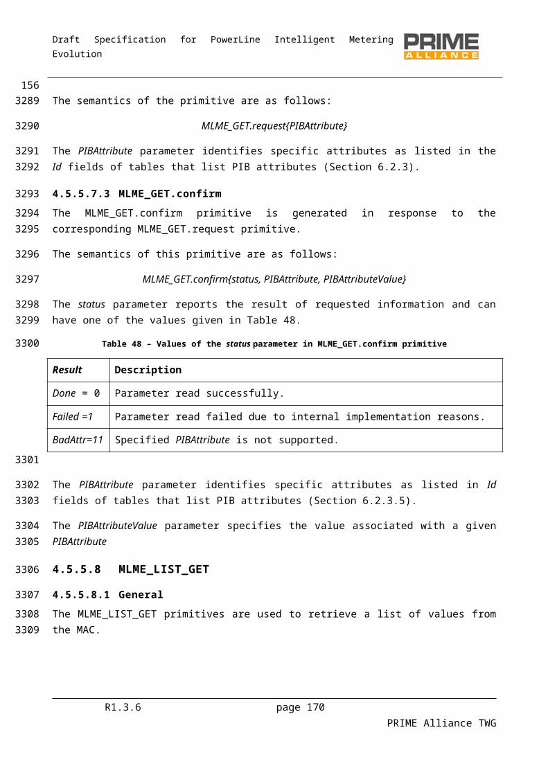
Draft Specification for PowerLine Intelligent Metering Evolution
IPv4 SSCS cannot join the group, it uses the CL_IPv4_IGMP_LEAVE.confirm primitive. Otherwise the CL_IPv4_IGMP_JOIN.confirm primitive is used to indicate success.
5.4.8.4.3 CL_IPv4_IGMP_JOIN.confirm
This primitive is passed from the IPv4 SSCS to the IPv4. It contains a result status and an IPv4 multicast address that was joined.
The semantics of this primitive are as follows:
CL_IPv4_IGMP_JOIN.confirmIPv4
The IPv4 address is the IPv4 multicast group that was joined. The IPv4 SSCS will start forwarding IPv4 multicast packets for the given multicast group.
5.4.8.4.4 CL_IPv4_IGMP_LEAVE.request
This primitive is passed from the IPv4 layer to the IPv4 SSCS. It contains an IPv4 multicast address to be left.
The semantics of this primitive are as follows:
CL_IPv4_IGMP_LEAVE.requestIPv4
The IPv4 address is the IPv4 multicast group to be left. The IPv4 SSCS will stop forwarding IPv4 multicast packets for this group and may leave the OFDM PRIME MAC multicast group.
5.4.8.4.5 CL_IPv4_IGMP_LEAVE.confirm
This primitive is passed from the IPv4 SSCS to the IPv4. It contains a result status and an IPv4 multicast address that was left.
The semantics of this primitive are as follows:
CL_IPv4_IGMP_LEAVE.confirmIPv4, Result
The IPv4 address is the IPv4 multicast group that was left. The IPv4 SSCS will stop forwarding IPv4 multicast packets for the given multicast group.
The Result takes a value from Table 134.
This primitive can be used by the IPv4 SSCS as a result of a CL_IPv4_IGMP_JOIN.request, CL_IPv4_IGMP_LEAVE.request or because of an error condition resulting in the loss of the OFDM PRIME MAC multicast connection.
5.4.8.5 Data transfer
5.4.8.5.1 General
The following primitives are used to send and receive IPv4 packets.
5.4.8.5.2 CL_IPv4_DATA.request
This primitive is passed from the IPv4 layer to the IPv4 SSCS. It contains one IPv4 packet to be sent.
R1.3.6 page 170 PRIME Alliance TWG
35023503
3504
35053506
3507
3508
35093510
3511
3512
3513
3514
35153516
3517
35183519
3520
3521
35223523
3524
352535263527
3528
3529
3530
3531
3532
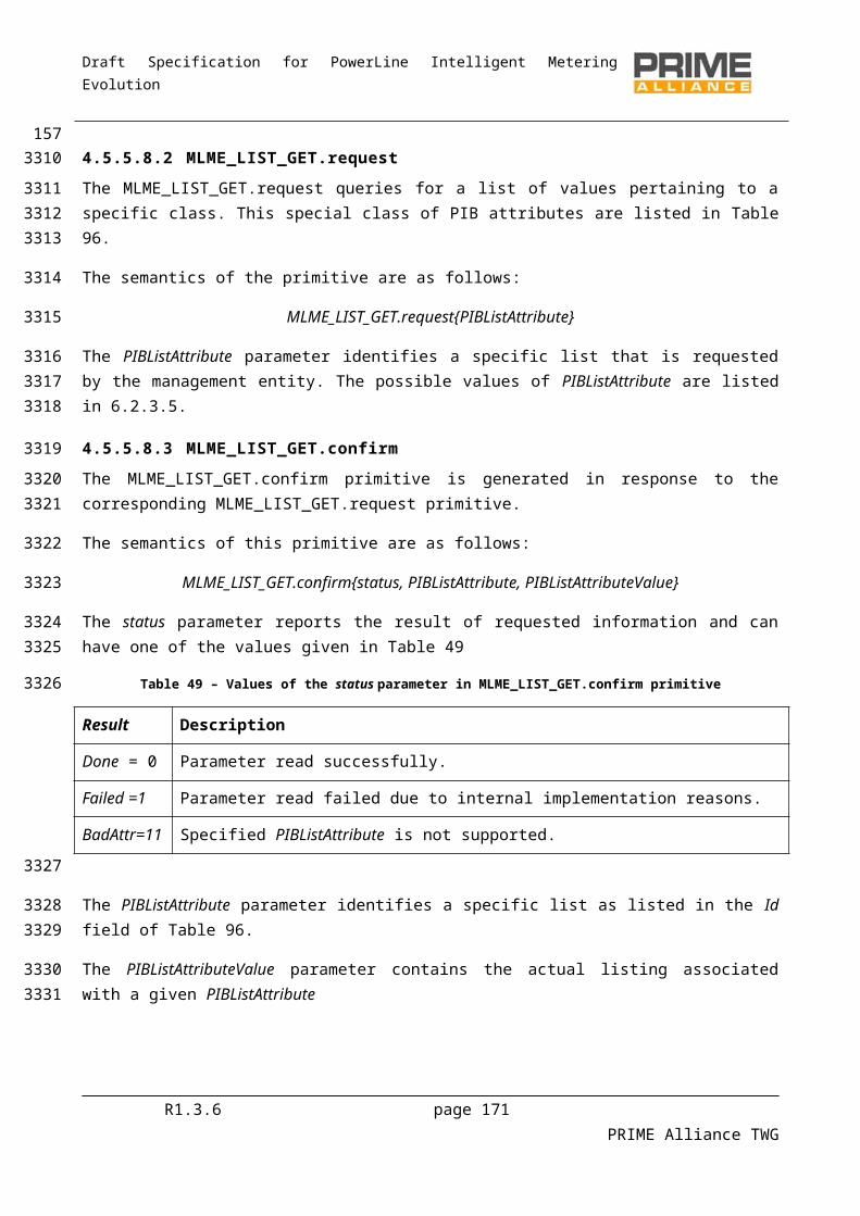
Draft Specification for PowerLine Intelligent Metering Evolution
The semantics of this primitive are as follows:
CL_IPv4_DATA.requestIPv4_PDU
The IPv4_PDU is the IPv4 packet to be sent.
5.4.8.5.3 CL_IPv4_DATA.confirm
This primitive is passed from the IPv4 SSCS to the IPv4 layer. It contains a status indication and an IPv4 packet that has just been sent.
The semantics of this primitive are as follows:
CL_IPv4_DATA.confirmIPv4_PDU, Result
The IPv4_PDU is the IPv4 packet that was to be sent.
The Result value indicates whether the packet was sent or an error occurred. It takes a value from Table134.
5.4.8.5.4 CL_IPv4_DATA.indicate
This primitive is passed from the IPv4 SSCS to the IPv4 layer. It contains an IPv4 packet that has just been received.
The semantics of this primitive are as follows:
CL_IPv4_DATA.indicateIPv4_PDU
The IPv4_PDU is the IPv4 packet that was received.
5.5 IEC 61334-4-32 Service-Specific Convergence Sublayer (IEC 61334-4-32 SSCS)
5.5.1 GeneralFor all the service required, the IEC 61334-4-32 SSCS supports the DL_DATA primitives as defined in the IEC 61334-4-32 standard. IEC 61334-4-32 should be read at the same time as this section, which is not standalone text.
5.5.2 OverviewThe IEC 61334-4-32 SSCS provides convergence functions for applications that use IEC 61334-4-32 services. Implementations conforming to this SSCS shall offer all LLC basic and management services as specified in IEC 61334-4-32 (1996-09 Edition), subsections 2.2.1 and 2.2.3. Additionally, the IEC 61334-4-32 SSCS specified in this section provides extra services that help mapping this connection-less IEC 61334-4-32 LLC protocol to the connection-oriented nature of MAC.
A Service Node can only exchange data with the Base Node and not with other Service Nodes. This meets all the requirements of IEC 61334-4-32, which has similar restrictions.
R1.3.6 page 171 PRIME Alliance TWG
3533
3534
3535
3536
35373538
3539
3540
3541
35423543
3544
35453546
3547
3548
3549
3550
3551
3552
355335543555
3556
35573558355935603561
35623563

Draft Specification for PowerLine Intelligent Metering Evolution
Each IEC 61334-4-32 SSCS session establishes a dedicated OFDM PRIME MAC connection for exchanging unicast data with the Base Node.
The Service Node SSCS session is responsible for initiating this connection to the Base Node. The Base Node SSCS cannot initiate a connection to a Service Node.
Each IEC 61334-4-32 SSCS listens to a OFDM PRIME broadcast MAC connection dedicated to the transfer of IEC 61334-4-32 broadcast data from the Base Node to the Service Nodes. This broadcast connection is used when applications in the Base Node using IEC 61334-4-32 services make a transmission request with the Destination_address used for broadcast or the broadcast SAP functions are used. When there are multiple SSCS sessions within a Service Node, one OFDM PRIME broadcast MAC connection is shared by all the SSCS sessions.
A CPCS session is always present with a IEC 61334-4-32 SSCS session. The SPCS sublayer functionality is as specified in Section 5.2.2. Thus, the MSDUs generated by IEC 61334-4-32 SSCS are always less than ClMTUSize bytes and application messages shall not be longer than ClMaxAppPktSize.
5.5.3 Address allocation and connection establishmentEach 4-32 connection will be identified with the "Application unique identifier" that will be communicating through this 4-32 connection. It is the scope of the communication profile based on these lower layers to define the nature and rules for, this unique identifier. Please refer to the future prTS/EN52056-8-4 for the DLMS/COSEM profile unique identifier. As long as the specification of the 4-32 Convergence layer concerns this identifier will be called the "Device Identifier".
The protocol stack as defined in IEC 61334 defines a Destination address to identify each device in the network. This Destination address is specified beyond the scope of the IEC 61334-4-32 document. However, it is used by the document. So that OFDM PRIME devices can make use of the 4-32 layer, this Destination address is also required and is specified here. For more information about this Destination address, please see IEC 61334-4-1 section 4.3, MAC Addresses.
The Destination address has a scope of one OFDM PRIME Subnetwork. The Base Node 4-32 SSCP layer is responsible for allocating these addresses dynamically and associating the Device Identifier of the Service Nodes SSCP session device with the allocated Destination address, according to the IEC-61334-4-1 standard. The procedure is as follows:
When the Service Node IEC 61334-4-32 SSCS session is opened by the application layer, it passes the Device Identifier of the device. The IEC 61334-4-32 SSCS session then establishes its unicast connection to the Base Node. This unicast connection uses the OFDM PRIME MAC TYPE value TYPE_CL_432, as defined in Table132. The connection request packet sent from the Service Node to the Base Node contains a data parameter. This data parameter contains the Device Identifier. The format of this data is specified in section 5.5.4.2.
On receiving this connection request at the Base Node, the Base Node allocates a unique Subnetwork Destination address to the Service Nodes SSCS session. The Base Node sends back a OFDM PRIME MAC connection response packet that contains a data parameter. This data parameter contains the allocated Destination address and the address being used by the Base Node itself. The format of this data parameter is defined in section 5.5.4.2. A 4-32 CL SAP primitive is used in the Base Node to indicate this new Service
R1.3.6 page 172 PRIME Alliance TWG
3564356535663567356835693570357135723573357435753576
3577
35783579358035813582
35833584358535863587
3588358935903591
359235933594359535963597
35983599360036013602
Draft Specification for PowerLine Intelligent Metering Evolution
Node SSCS session mapping of Device Identifier and Destination_address to the 4-32 application running in the Base Node.
On receiving the connection establishment and the Destination_address passed in the OFDM PRIME MAC connection establishment packet, the 4-32 SSCS session confirms to the application that the Convergence layer session has been opened and indicates the Destination_address allocated to the Service Node SSCS session and the address of the Base Node. The Service Node also opens a OFDM PRIME MAC broadcast connection with LCID equal to LCI_CL_432_BROADCAST, as defined in Table 133, if no other SSCS session has already opened such a broadcast connection This connection is used to receive broadcast packets sent by the Base Node 4-32 Convergence layer to all Service Node 4-32 Convergence layer sessions.
If the Base Node has allocated all its available Destination_addresses, due to the exhaustion of the address space or implementation limits, it should simply reject the connection request from the Service Node. The Service Node may try to establish the connection again. However, to avoid overloading the OFDM PRIME Subnetwork with such requests, it should limit such connection establishments to one attempt per minute when the Base Node rejects a connection establishment.
When the unicast connection between a Service Node and the Base Node is closed (e.g. because the Convergence layer on the Service Node is closed or the OFDM PRIME MAC level connection between the Service Node and the Base Node is lost), the Base Node will deallocate the Destination_address allocated to the Service Node SSCS session. The Base Node will use a 4-32 CL SAP (CL_432_Leave.indication) primitive to indicate the deallocation of the Destination_address to the 4-32 application running on the Base Node
5.5.4 Connection establishment data format
5.5.4.1 General
As described in section 5.5.3, the MAC OFDM PRIME connection data is used to transfer the Device Identifier to the Base Node and the allocated Destination_address to the Service Node SSCS session. This section describes the format used for this data.
5.5.4.2 Service Node to Base Node
The Service Node session passes the Device Identifier to the Base Node as part of the connection establishment request. The format of this message is shown in Table 71.
Table 71 - Connection Signalling Data sent by the Service Node
Name Length Description
Data.SN n-Octets Device Identifier.“COSEM logical device name" of the "Management logical device" of the DLMS/COSEM device as specified in the DLMS/COSEM, which will be communicating through this 4-32 connection.
R1.3.6 page 173 PRIME Alliance TWG
36033604
3605360636073608360936103611
36123613361436153616
36173618361936203621
3622
3623
362436253626
3627
36283629
3630

Draft Specification for PowerLine Intelligent Metering Evolution
5.5.4.3 Base Node to Service Node
The Base Node passes the allocated Destination_address to the Service Node session as part of the connection establishment request. It also gives its own address to the Service Node. The format of this message is shown in Table 72.
Table 72 - Connection Signalling Data sent by the Base Node
Name Length Description
Reserved 4-bits Reserved. Should be encoded as zero in this version of the specification.
Data.DA 12-bits Destination_address allocated to the Service Node.
Reserved 4-bits Reserved. Should be encoded as zero in this version of the specification.
Data.BA 12-bits Base_address used by the Base Node.
5.5.5 Packet formatThe packet formats are used as defined in IEC 61334-4-32, Clause 4, LLC Protocol Data Unit Structure (LLC_PDU).
5.5.6 Service Access Point
5.5.6.1 Opening and closing the Convergence layer at the Service Node
5.5.6.1.1 CL_432_ESTABLISH.request
This primitive is passed from the application to the 4-32 Convergence layer. It is used to open a Convergence layer session and initiate the process of registering the Device Identifier with the Base Node and the Base Node allocating a Destination_address to the Service Node session.
The semantics of this primitive are as follows:
CL_432_ESTABLISH.request DeviceIdentifier
The Device Identifier is that of the device to be registered with the Base Node.
If the Device Identifier is registered and the Convergence layer session is successfully opened, the primitive CL_432_ESTABLISH.confirm is used. If an error occurs the primitive CL_432_RELEASE.confirm is used.
5.5.6.1.2 CL_432_ESTABLISH.confirm
This primitive is passed from the 4-32 Convergence layer to the application. It is used to confirm the successful opening of the Convergence layer session and that data may now be passed over the Convergence layer.
The semantics of this primitive are as follows:
CL_432_ESTABLISH.confirm DeviceIdentifier, Destination_address, Base_address R1.3.6 page 174 PRIME Alliance TWG
3631
363236333634
3635
3636
3637
36383639
3640
3641
3642
364336443645
3646
3647
3648
36493650
3651
365236533654
3655
3656
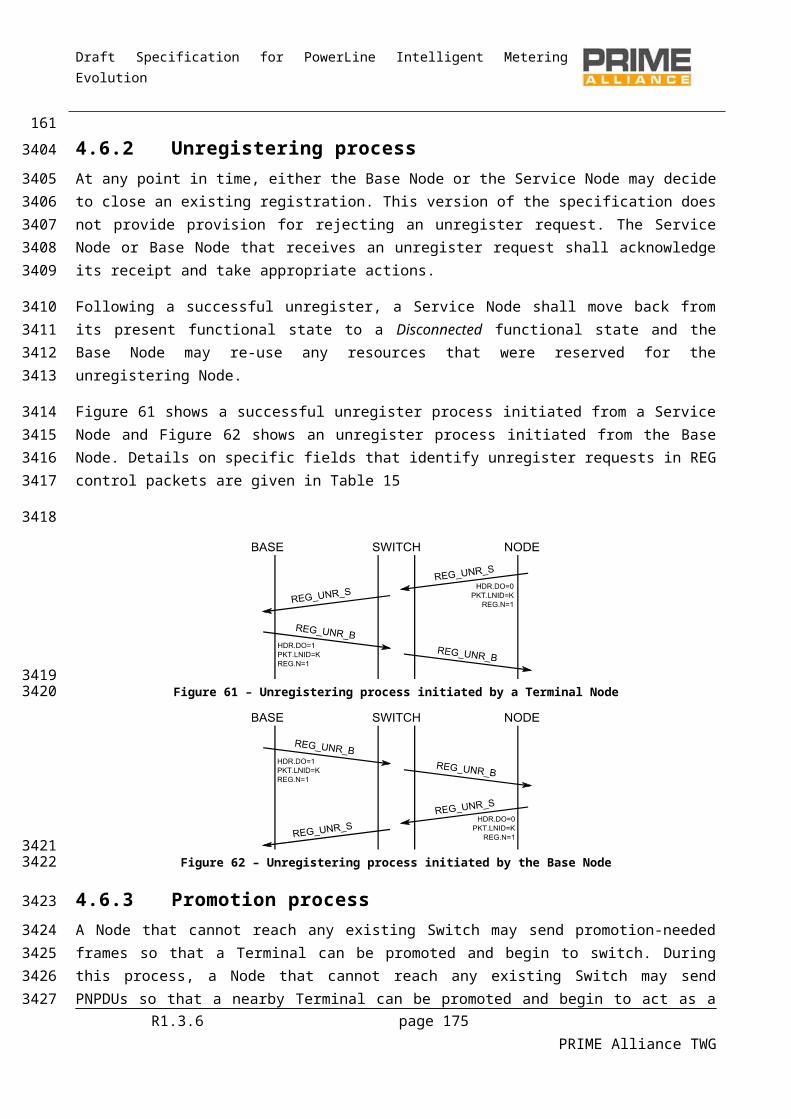
Draft Specification for PowerLine Intelligent Metering Evolution
The Device Identifier is used to identify which CL_432_ESTABLISH.request this CL_432_ESTABLISH.confirm is for.
The Destination_address is the address allocated to the Service Node 4-32 session by the Base Node.
The Base_address is the address being used by the Base Node.
5.5.6.1.3 CL_432_RELEASE.request
This primitive is passed from the application to the 4-32 Convergence layer. It is used to close the Convergence layer and release any resources it may be holding.
The semantics of this primitive are as follows:
CL_432_RELEASE.requestDestination_address
The Destination_address is the address allocated to the Service Node 4-32 session which is to be closed.
The Convergence layer will use the primitive CL_432_RELEASE.confirm when the Convergence layer session has been closed.
5.5.6.1.4 CL_432_RELEASE.confirm
This primitive is passed from the 4-32 Convergence layer to the application. The primitive tells the application that the Convergence layer session has been closed. This could be because of a CL_432_RELEASE.request or because an error has occurred, forcing the closure of the Convergence layer session.
The semantics of this primitive are as follows:
CL_432_RELEASE.confirmDestination_address, result
The Handle identifies the session which has been closed.
The result parameter has the meanings defined in Table 134.
5.5.6.2 Opening and closing the Convergence layer at the Base Node
No service access point primitives are defined at the Base Node for opening or closing the Convergence layer. None are required since the 4-32 application in the Base Node does not need to pass any information to the 4-32 Convergence layer in the Base Node.
5.5.6.3 Base Node indications
5.5.6.3.1 General
The following primitives are used in the Base Node 4-32 Convergence layer to indicate events to the 4-32 application in the Base Node. They indicate when a Service Node session has joined or left the network.
R1.3.6 page 175 PRIME Alliance TWG
3657
36583659
3660
3661
3662
36633664
3665
3666
3667
36683669
3670
3671367236733674
3675
3676
3677
3678
3679
368036813682
3683
3684
36853686
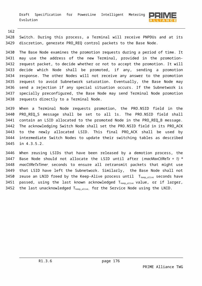
Draft Specification for PowerLine Intelligent Metering Evolution
5.5.6.3.2 CL_432_JOIN.indicate
CL_432_JOIN.indicate Device Identifier, Destination_address
The Device Identifier is that of the device connected to the Service Node that has just joined the network.
The Destination_address is the address allocated to the Service Node by the Base Node.
5.5.6.3.3 CL_432_LEAVE.indicate
CL_432_LEAVE.indicateDestination_address
The Destination_address is the address of the Service Node session that just left the network.
5.5.6.4 Data Transfer Primitives
The data transfer primitives are used as defined in IEC 61334-4-32, sections 2.2, 2.3, 2.4 and 2.11, LLC Service Specification. As stated earlier, OFDM PRIME 432 SSCS make the use of IEC61334-4-32 DL_Data service (.req, .conf, .ind) for carrying out all the data involved during data transfer.
5.6 IPv6 Service-Specific Convergence Sublayer (IPv6 SSCS)
5.6.1 Overview
5.6.1.1 General
The IPv6 convergence layer provides an efficient method for transferring IPv6 packets over the PRIME network.
A Service Node can pass IPv6 packets to the Base Node or directly to other Service Nodes.
By default, the Base Node acts as a router between the PRIME subnet and the backbone network. All the Base Nodes must have at least this connectivity capability. Any other node inside the Subnetwork can also act as a gateway. The Base Node could also act as a NAT router. However given the abundance of IPv6 addresses this is not expected. How the Base Node connects to the backbone is beyond the scope of this standard.
5.6.1.2 IPv6 unicast addressing assignment
IPv6 Service Nodes (and Base Nodes) shall support the standard IPv6 protocol, as described in RFC 2460.
IPv6 Service Nodes (and Base Nodes) shall support the standard IPv6 addressing architecture, as described in RFC 4291.
IPv6 Service Nodes (and Base Nodes) shall support global unicast IPv6 addresses, link-local IPv6 addresses and multicast IPv6 addresses, as described in RFC 4291.
IPv6 Service Nodes (and Base Nodes) shall support automatic address configuration using stateless address configuration [RFC 2462]. They may also support automatic address configuration using
R1.3.6 page 176 PRIME Alliance TWG
3687
3688
3689
3690
3691
3692
3693
3694
369536963697
3698
3699
3700
3701
37023703
3704
37053706370737083709
3710
37113712371337143715371637173718
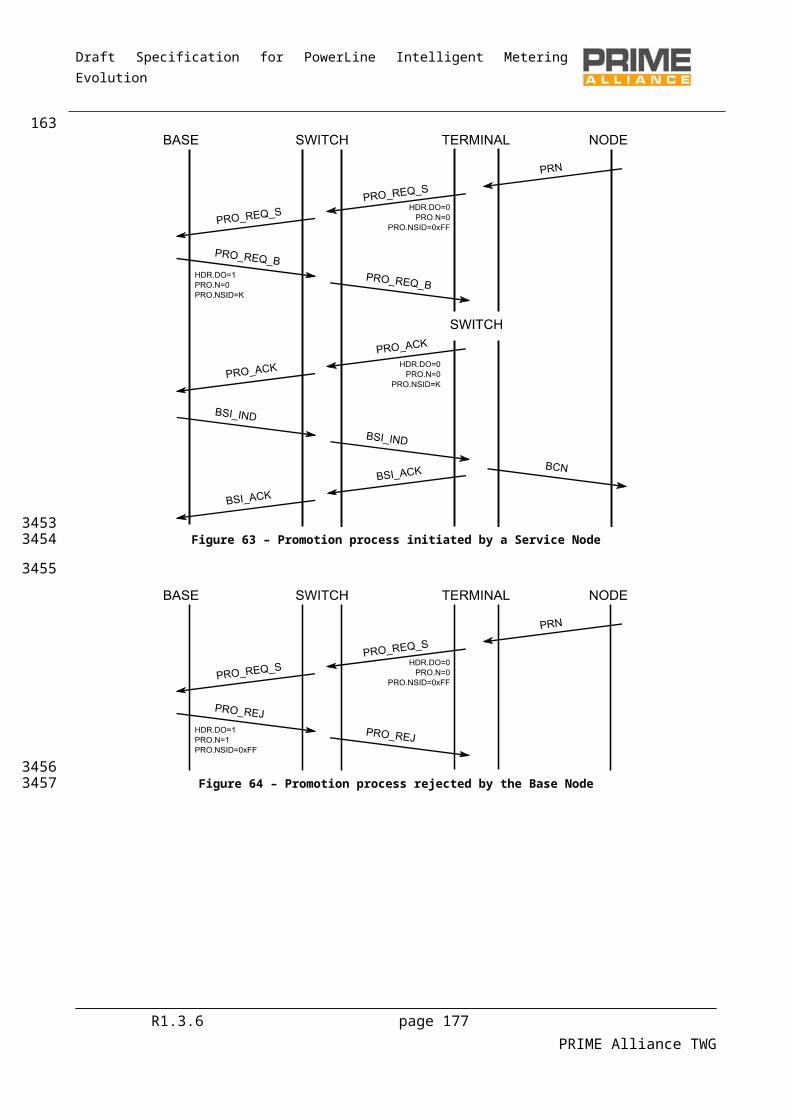
Draft Specification for PowerLine Intelligent Metering Evolution
stateful address configuration [RFC 3315] and they may support manual configuration of IPv6 addresses. The decision of which address configuration scheme to use is deployment specific.
Service Node shall support DHCPv6 client, when Base Nodes have to support DHCPv6 server as described in RFC 3315 for stateless address configuration
5.6.1.3 Address management in PRIME Subnetwork
Packets are routed in PRIME Subnetwork according to the node identifier NID. Node identifier is a combination of Service Node’s LNID and SID (see section 4.2). The Base Node is responsible of assigning LNID to Service Nodes. During the registration process which leads to a LNID assignment to the related Service Node, the Base Node registers the Service Node EUI-48, and the assigned LNID together with SID.
At the convergence layer level, addressing is performed using the EUI-48 of the related Service Node. The role of the convergence sublayer is to resolve the IPv6 address into EUI-48 of the Service Node. This is done using the address resolution service set of the Base Node.
5.6.1.4 Role of the Base Node
At the convergence sublayer level, the Base Node maintains a table containing all the IPv6 unicast addresses and the EUI-48 related to them. One of the roles of the Base Node is to perform IPv6 to EUI-48 address resolution. Each Service Node belonging to the Subnetwork managed by the Base Node, registers its IPv6 address and EUI-48 address with the Base Node. Other Service Nodes can then query the Base Node to resolve an IPv6 address into a EUI-48 address. This requires the establishment of a dedicated connection to the Base Node for address resolution, which is shared by both IPv4 and IPv6 address resolution.
Optionally UDP/IPv6 headers may be compressed. Compression is negotiated as part of the connection establishment phase. Currently one header compression technique is described in the present specification that used for transmission of IPv6 packets over IEEE 802.15.4 networks, as defined in RFC6282. This is also known as LOWPAN_IPHC1.
The multicasting of IPv6 packets is supported using the MAC multicast mechanism
5.6.2 IPv6 Convergence layer
5.6.2.1 Overview
5.6.2.1.1 General
The convergence layer has a number of connection types. For address resolution there is a connection to the Base Node. For IPv6 data transfer there is one connection per destination node: the Base Node that acts as the IPv6 gateway to the outside world or another node in the same Subnetwork. This is shown in Figure 99.
R1.3.6 page 177 PRIME Alliance TWG
37193720372137223723
3724
3725372637273728
372937303731
3732
3733373437353736373737383739
3740374137423743
3744
3745
3746
3747
3748374937503751

Draft Specification for PowerLine Intelligent Metering Evolution
Figure 99 - Example of IPv6 Connection
Here, nodes B, E and F have address resolution connections to the Base Node. Node E has a data connection to the Base Node and node F. Node F is also has a data connection to node B. The figure does not show broadcast-traffic and multicast-traffic connections.
5.6.2.1.2 Routing in the Subnetwork
Routing IPv6 packets is the scope of the Convergence layer. In other words, the convergence layer will decide whether the packet should be sent directly to another Service Node or forwarded to the configured gateway depending on the IPv6 destination address.
Although IPv6 is a connectionless protocol, the IPv6 convergence layer is connection-oriented. Once address resolution has been performed, a connection is established between the source and destination Service Nodes for the transfer of IP packets. This connection is maintained all the time the traffic is being transferred and may be removed after a period of inactivity.
5.6.2.1.3 SAR
The CPCS sublayer shall always be present with the IPv6 convergence layer allowing segmentation and reassembly facilities. The SAR sublayer functionality is given in Section 5.2. Thus, the MSDUs generated by the IPv6 convergence layer are always less than ClMTUSize bytes and application messages are expected to be no longer than ClMaxAppPktSize.
5.6.3 IPv6 Address Configuration
5.6.3.1 Overview
The Service Nodes may use statically configured IPv6 addresses, link local addresses, stateless or stateful auto-configuration according to RFC 2462, or DHCPv6 to obtain IPv6 addresses. All the Nodes shall support the unicast link local address, in addition with other configured addresses below, and multicast addresses, if ever the node belong to multicast groups.
R1.3.6 page 178 PRIME Alliance TWG
3752
3753
375437553756
3757
375837593760
3761376237633764
3765
3766376737683769
3770
3771
3772377337743775
Draft Specification for PowerLine Intelligent Metering Evolution
5.6.3.2 Interface identifier
In order to make use of stateless address auto configuration and link local addresses it is necessary to define how the Interface identifier, as defined in RFC4291, is derived. Each PRIME node has a unique EUI-48. This EUI-48 is converted into an EUI-64 in the same way as for Ethernet networks as defined in RFC2464. This EUI-64 is then used as the Interface Identifier.
5.6.3.3 IPv6 Link local address configuration
The IPv6 Link local address of a PRIME interface is formed by appending the Interface Identifier as defined above to the Prefix FE80::/64.
5.6.3.4 Stateless address configuration
An IPv6 address prefix used for stateless auto configuration, as defined in RFC4862, of a PRIME interface shall have a length of 64 bits. The IPv6 prefix is obtained by the Service Nodes from the Base Node via Router Advertisement messages, which are send periodically or on request by the Base Node.
5.6.3.5 Stateful address configuration
An IPv6 address can be alternatively configured using DHCPv6, as described in RFC 3315. DHCPv6 can provide a device with addresses assigned by a DHCPv6 server and other configuration information, which are carried in options.
5.6.3.6 Multicast address
IPv6 Service Nodes (and Base Nodes) shall support the multicast IPv6 addressing, as described in RFC 4291 section 2.7.
5.6.3.7 Address resolution
5.6.3.7.1 Overview
The IPv6 layer will present the convergence layer with an IPv6 packet to be transferred. The convergence layer is responsible for determining which Service Node the packet should be delivered to, using the IPv6 addresses in the packet. The convergence layer shall then establish a connection to the destination if one does not already exist so that the packet can be transferred. Two classes of IPv6 addresses can be used and the following section describes how these addresses are resolved into PRIME EUI-48 addresses. It should be noted that IPv6 does not have a broadcast address. However broadcasting is possible using multicast all nodes addresses.
5.6.3.7.2 Unicast address
5.6.3.7.2.1 General
IPv6 unicast addresses shall be resolved into PRIME unicast EUI-48 addresses. The Base Node maintains a central database Node of IPv6 addresses and EUI-48 addresses. Address resolution functions are performed by querying this database. The Service Node shall establish a connection to the address resolution service running on the Base Node, using the TYPE value TYPE_CL_IPv6_AR. No data should be passed in the
R1.3.6 page 179 PRIME Alliance TWG
3776
3777377837793780
3781
37823783
3784
378537863787
3788
378937903791
3792
37933794
3795
3796
3797379837993800380138023803
3804
3805
3806
3807380838093810
Draft Specification for PowerLine Intelligent Metering Evolution
connection establishment signalling. Using this connection, the Service Node can use two mechanisms as defined in the present specification.
5.6.3.7.2.2 Address registration and deregistration
A Service Node uses the AR_REGISTERv6_S message to register an IPv6 address and the corresponding EUI-48 address. The Base Node will acknowledge an AR_REGISTERv6_B message. The Service Node may register multiple IPv6 addresses for the same EUI-48.
A Service Node uses the AR_UNREGISTERv6_S message to unregister an IPv6 address and the corresponding EUI-48 address. The Base Node will acknowledge with an AR_UNREGISTERv6_B message.
When the address resolution connection between the Service Node and the Base Node is closed, the Base Node should remove all addresses associated with that connection.
5.6.3.7.2.3 Address lookup
A Service Node uses the AR_LOOKUPv6_S message to perform a lookup. The message contains the IPv6 address to be resolved. The Base Node will respond with an AR_LOOKUPv6_B message that contains an error code and, if there is no error, the EUI-48 associated with the IPv6 address. If the Base Node has multiple entries in its database Node for the same IPv6 address, the possible EUI-48 returned is undefined.
It should be noted that, for the link local addresses, due to the fact that the EUI-48 can be obtained from the IPv6 address, the lookup can simply return this value by extracting it from the IPv6 address.
5.6.3.7.3 Multicast address
Multicast IPv6 addresses are mapped to connection handles (ConnHandle) by the Convergence Layer.
To join a multicast group, CL uses the MAC_JOIN.request primitive with the IPv6 address specified in the data field. A corresponding MAC_JOIN.Confirm primitive will be generated by the MAC after completion of the join process. The MAC_Join.Confirm primitive will contain the result (success/failure) and the corresponding ConnHandle to be used by the CL. The MAC layer will handle the transfer of data for this connection using the appropriate LCIDs. To leave the multicast group, the CL at the service node shall use the MAC-LEAVE.RequestConnHandle primitive.
To send an IPv6 multicast packet, the CL will simply send the packet to the group, using the allocated ConnHandle. The ConnHandle is maintained while there are more packets to be sent. However, after Tmcast_reg seconds of not sending an IPv6 multicast packet to the group, the node should release the ConnHandle by using the MAC-LEAVE.Request primitive. The nominal value of Tmcast_reg is 10 minutes; however, other values may be used.
5.6.3.7.4 Retransmission of address resolution packets
The connection between the Service Node and the Base Node for address resolution is not reliable. The MAC ARQ is not used. The Service Node is responsible for making retransmissions if the Base Node does
R1.3.6 page 180 PRIME Alliance TWG
38113812
3813
3814
381538163817
38183819
38203821
3822
3823
3824382538263827
38283829
3830
3831
383238333834383538363837
38383839384038413842
3843
38443845
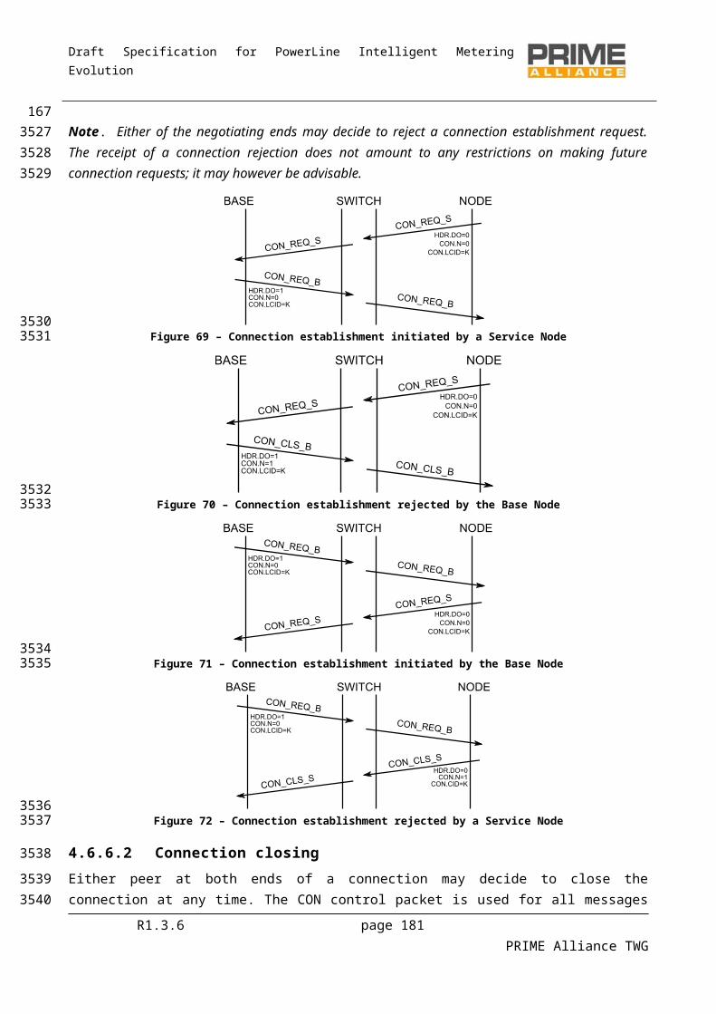
Draft Specification for PowerLine Intelligent Metering Evolution
not respond in one second. It is not considered an error when the Base Node receives the same registration requests multiple times or is asked to remove a registration that does not exist. These conditions can be the result of retransmissions.
5.6.4 IPv6 Packet TransferFor packets to be transferred, a connection needs to be established between the source and destination nodes. The IPv6 convergence layer will examine each IP packet to determine the destination EUI-48 address. If a connection to the destination has already been established, the packet is simply sent. To establish this, the convergence layer keeps a table for each connection it has with information shown in Table 73. To use this table, it is first necessary to determine if the remote address is in the local subnet or if ever a gateway has to be used. The netmask associated with the local IP address is used to determine this. If the destination address is not in the local Subnetwork, the address of the gateway is used instead of the destination address when the table is searched.
Table 73 – IPv6 convergence layer table entry
Parameter Description
CL_IPv6_Con.Remote_IP Remote IP address of this connection
CL_IPv6_Con.ConHandle MAC Connection handle for the connection
CL_IPv6_Con.LastUsed Timestamp of last packet received/transmitted
CL_IPv6_Con.HC Header Compression scheme being used
The convergence layer may close a connection when it has not been used for an implementation-defined time period. When the connection is closed the entry for the connection is removed at both ends of the connection.
When a connection to the destination does not exist, more work is necessary. The address resolution service is used to determine the EUI-48 address of the remote IP address if it is local or the gateway associated with the local address if the destination address is in another subnet. When the Base Node replies with the EUI-48 address of the destination Service Node, a MAC connection is established to the remote device. The TYPE value of this connection is TYPE_CL_IPv6_UNICAST. The data passed in the request message is defined in section 5.6.8.3. The local IP address is provided so that the remote device can add the new connection to its cache of connections for sending data in the opposite direction. The use of header compression is also negotiated as part of the connection establishment. Once the connection has been established, the IP packet can be sent.
5.6.5 Segmentation and reassemblyThe IPv6 convergence layer should support IPv6 packets with an MTU of 1500 bytes. This requires the use of the common part convergence sublayer segmentation and reassembly service.
R1.3.6 page 181 PRIME Alliance TWG
384638473848
3849
38503851385238533854385538563857
3858
385938603861
386238633864386538663867386838693870
3871
38723873
3874
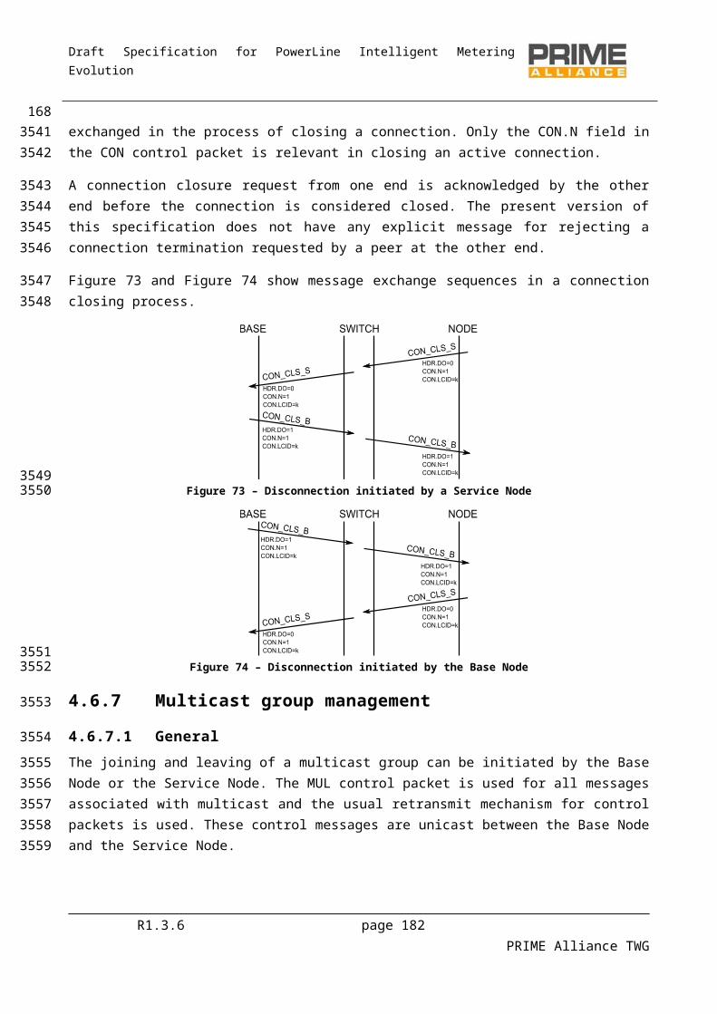
Draft Specification for PowerLine Intelligent Metering Evolution
5.6.6 CompressionIt is assumed that any PRIME device capable of LOWPAN_IPHC IPv6 header compression/decompression. It may also be also capable of performing UDP compression/decompression. Thus UDP/IPv6 compression is negotiated.
No negotiation can take place for multicast packet. Nodes can only make use of mandatory compression capabilities
Depending of the type of IPv6 address carried by the packet and the capabilities which are negotiated between the nodes involved in the data exchanges, IPv6 header compression is performed.
All the Service Nodes and the Base Node shall support IPv6 Header Compression using source and destination Addresses stateless compression as defined in RFC 6282. Source and destination IPv6 addresses using stateful compression and IPv6 Next header compression are negotiable.
5.6.7 Quality of Service MappingThe PRIME MAC specifies that the contention-based access mechanism supports 4 priority levels (1-4). Level 1 is used for MAC signalling messages, but not exclusively so.
IPv6 packets include a Traffic Class field in the header to indicate the QoS the packet would like to receive. This traffic class can be used in the same way that IPv4 TOS (see [7]). That is, three bits of the TOS indicate the IP Precedence. The following table specifies how the IP Precedence is mapped into the PRIME MAC priority.
Table 74 – Mapping Ipv6 precedence to PRIME MAC priority
IP Precedence MAC Priority
000 – Routine 4
001 – Priority 4
010 – Immediate 3
011 – Flash 3
100 – Flash Override 2
101 – Critical 2
110 – Internetwork Control 1
111 – Network Control 1
Note: At the MAC layer level the priority as stated in the Packet header field is the value assigned in this table minus 1, as the range of PKT.PRIO field is from 0 to 3.
R1.3.6 page 182 PRIME Alliance TWG
3875
387638773878
38793880
38813882
388338843885
3886
38873888
3889389038913892
3893
3894
38953896

Draft Specification for PowerLine Intelligent Metering Evolution
5.6.8 Packet formats and connection data
5.6.8.1 Overview
This section defines the format of convergence layer PDUs.
5.6.8.2 Address resolution PDU
5.6.8.2.1 General
The following PDUs are transferred over the address resolution connection between the Service Node and the Base Node. The following sections define a number of AR.MSG values. All other values are reserved for later versions of this standard.
5.6.8.2.2 AR_REGISTERv6_S
Table 75 shows the address resolution register message sent from the Service Node to the Base Node.
Table 75 - AR_REGISTERv6_S message format
Name Length Description
AR.MSG 8-bits Address Resolution Message Type
For AR_REGISTERv6_S = 16
AR.IPv6 128-bits IPv6 address to be registered
AR.EUI-48 48-bits EUI-48 to be registered
AR_REGISTERv6_B
Table 76 shows the address resolution register acknowledgment message sent from the Base Node to the Service Node.
Table 76 - AR_REGISTERv6_B message format
Name Length Description
AR.MSG 8-bits Address Resolution Message Type
For AR_REGISTERv6_B = 17
AR.IPv6 128-bits IPv6 address registered
AR.EUI-48 48-bits EUI-48 registered
The AR.IPv6 and AR.EUI-48 fields are included in the AR_REGISTERv6_B message so that the Service Node can perform multiple overlapping registrations.
R1.3.6 page 183 PRIME Alliance TWG
3897
3898
3899
3900
3901
390239033904
3905
3906
3907
3908
3909
39103911
3912
3913
39143915

Draft Specification for PowerLine Intelligent Metering Evolution
5.6.8.2.3 AR_UNREGISTERv6_S
Table 77 shows the address resolution unregister message sent from the Service Node to the Base Node.
Table 77 - AR_UNREGISTERv6_S message format
Name Length Description
AR.MSG 8-bits Address Resolution Message Type
For AR_UNREGISTERv6_S = 18
AR.IPv6 128-bits IPv6 address to be unregistered
AR.EUI-48 48-bits EUI-48 to be unregistered
5.6.8.2.4 AR_UNREGISTERv6_B
Table 78 shows the address resolution unregister acknowledgment message sent from the Base Node to the Service Node.
Table 78 - AR_UNREGISTERv6_B message format
Name Length Description
AR.MSG 8-bits Address Resolution Message Type
For AR_UNREGISTERv6_B = 19
AR.IPv6 128-bits IPv6 address unregistered
AR.EUI-48 48-bits EUI-48 unregistered
The AR.IPv6 and AR.EUI-48 fields are included in the AR_UNREGISTERv6_B message so that the Service Node can perform multiple overlapping unregistrations.
5.6.8.2.5 AR_LOOKUPv6_S
Table 79 shows the address resolution lookup message sent from the Service Node to the Base Node.
Table 79 - AR_LOOKUPv6_S message format
Name Length Description
AR.MSG 8-bits Address Resolution Message Type
For AR_LOOKUPv6_S = 20
AR.IPv6 128-bits IPv6 address to lookup
R1.3.6 page 184 PRIME Alliance TWG
3916
3917
3918
3919
3920
39213922
3923
39243925
3926
3927
3928
3929
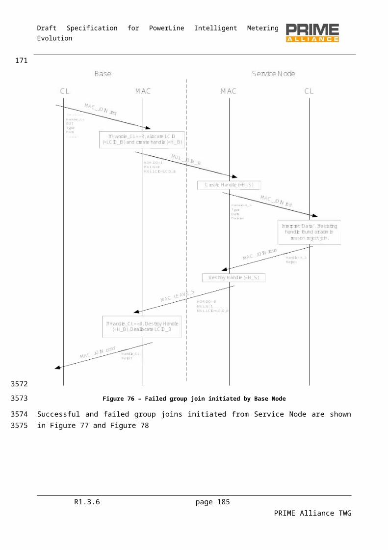
Draft Specification for PowerLine Intelligent Metering Evolution
5.6.8.2.6 AR_LOOKUPv6_B
Table 80 shows the address resolution lookup response message sent from the Base Node to the Service Node.
Table 80 - AR_LOOKUPv6_B message format
Name Length Description
AR.MSG 8-bits Address Resolution Message Type
For AR_LOOKUPv6_B = 21
AR.IPv6 128-bits IPv6 address looked up
AR.EUI-48 48-bits EUI-48 for IPv6 address
AR.Status 8-bits Lookup status, indicating if the address was found or an error occurred.
0 = found, AR.EUI-48 valid.
1 = unknown, AR.EUI-48 undefinedThe lookup may fail if the requested address has not been registered. In that case, AR.Status will have a value equal to 1, and the contents of AR.EUI-48 will be undefined. The lookup is only successful when AR.Status is zero. In that case, the EUI-48 field contains the resolved address.
5.6.8.2.7 AR_MCAST_REGv6_S
Table 81 shows the multicast address resolution register message sent from the Service Node to the Base Node.
Table 81 - AR_MCAST_REGv6_S message format
Name Length Description
AR.MSG 8-bits Address Resolution Message Type
For AR_MCAST_REGv6_S = 24
AR.IPv6 128-bits IPv6 multicast address to be registered
5.6.8.2.8 AR_MCAST_REGv6_B
Table 82 shows the multicast address resolution register acknowledgment message sent from the Base Node to the Service Node.
R1.3.6 page 185 PRIME Alliance TWG
3930
3931
39323933
3934
393539363937
3938
3939
39403941
3942
3943
3944
39453946
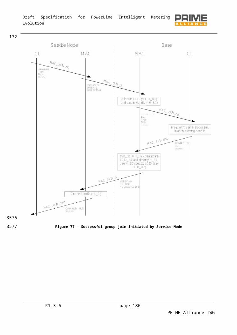
Draft Specification for PowerLine Intelligent Metering Evolution
Table 82 - AR_MCAST_REGv6_B message format
Name Length Description
AR.MSG 8-bits Address Resolution Message Type
For AR_MCAST_REGv6_B = 25
AR.IPv6 128-bits IPv6 multicast address registered
Reserved 2-bits Reserved. Should be encoded as 0.
AR.LCID 6-bits LCID assigned to this IPv6 multicast address
The AR.IPv6 field is included in the AR_MCAST_REGv6_B message so that the Service Node can perform multiple overlapping registrations.
5.6.8.2.9 AR_MCAST_UNREGv6_S
Table 83 shows the multicast address resolution unregister message sent from the Service Node to the Base Node.
Table 83 - AR_MCAST_UNREGv6_S message format
Name Length Description
AR.MSG 8-bits Address Resolution Message Type
For AR_MCAST_UNREGv6_S = 26
AR.IPv6 128-bits IPv6 multicast address to be unregistered
5.6.8.2.10 AR_MCAST_UNREGv6_B
Table 84 shows the multicast address resolution unregister acknowledgment message sent from the Base Node to the Service Node.
Table 84 - AR_MCAST_UNREGv6_B message format
Name Length Description
AR.MSG 8-bits Address Resolution Message Type
For AR_MCAST_UNREGv6_B = 27
AR.IPv6 128-bits IPv6 multicast address unregistered
The AR.IPv6 field is included in the AR_MCAST_UNREGv6_B message so that the Service Node can perform multiple overlapping unregistrations.
R1.3.6 page 186 PRIME Alliance TWG
3947
39483949
3950
39513952
3953
3954
3955
39563957
3958
39593960

Draft Specification for PowerLine Intelligent Metering Evolution
5.6.8.3 IPv6 Packet format
5.6.8.3.1 General
The following PDU formats are used for transferring IPv6 packets between Service Nodes.
5.6.8.3.2 No negotiated header compression
When no header compression take place, the IP packet is simply sent as it is, without any header.
Table 85 - IPv6 Packet format without negotiated header compression
Name Length Description
IPv6.PKT n-octets
The IPv6 Packet
5.6.8.3.3 Header compression
When LOWPAN_IPHC1 header compression takes place, and the next header compression is negotiated, the UDP/IPv6 packet is sent as shown in Table 86.
Table 86 - UDP/IPv6 Packet format with LOWPAN_IPHC1 header compression and LOWPAN_NHC
Name Length Description
IPv6.IPHC 2-octet Dispatch + LOWPAN_IPHC encoding. With bit 5=1 indicating that the next is compressed ,using LOWPAN_NHC format
IPv6.ncIPv6 n.m-octets Non-Compressed IPv6 fields (or elided)
IPv6.HC_UDP 1-octet Next header encoding
IPv6.ncUDP n.m-octets Non-Compressed UDP fields
Padding 0.m-octets Padding to byte boundary
IPv6.DATA n-octets UDP data
Note that these fields are not necessarily aligned to byte boundaries. For example the IPv6.ncIPv6 field can be any number of bits. The IPv6.IPHC_UDP field follows directly afterwards, without any padding. Padding is only applied at the end of the complete compressed UDP/IPv6 header such that the UDP data is byte aligned.
When the IPv6 packet contains data other than UDP the following packet format is used as shown in Table87.
Table 87 - IPv6 Packet format with LOWPAN_IPHC negotiated header compression
Name Length Description
R1.3.6 page 187 PRIME Alliance TWG
3961
3962
3963
3964
3965
3966
3967
3968
39693970
3971
3972397339743975
39763977
3978
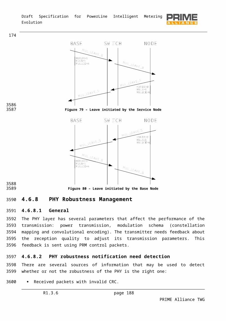
Draft Specification for PowerLine Intelligent Metering Evolution
IPv6.IPHC 2-octet HC encoding. Bits 5 contain 0 indicating the next header byte is not compressed.
IPv6.ncIPv6 n.m-octets Non-Compressed IPv6 fields
Padding 0.m-octets Padding to byte boundary
IPv6.DATA n-octets IP Data
5.6.8.4 Connection data
5.6.8.4.1 Overview
When a connection is established between Service Nodes for the transfer of IP packets, data is also transferred in the connection request packets. This data allows the negotiation of compression and notification of the IP address.
5.6.8.4.2 Connection data from the initiator
Table 88 shows the connection data sent by the initiator.
Table 88 - IPv6 Connection signalling data sent by the initiator
Name Length Description
Reserved 6-bits Should be encoded as zero in this version of the convergence layer protocol
Data.HCNH 2-bit Header Compression negotiated
Data.HC = 0 – No compression requested
Data.HC = 1 – LOWPAN_NH
Data.HC = 2 – stateful address compression.
Data.HC = 3 – LOWPAN_NH and stateful address compression.
Data.IPv6 128-bits IPv6 address of the initiator
If the device accepts the connection, it should copy the Data.IPv6 address into a new table entry along with the negotiated Data.HC value.
5.6.8.4.3 Connection data from the responder
R1.3.6 page 188 PRIME Alliance TWG
3979
3980
398139823983
3984
3985
3986
3987
39883989
3990
3991
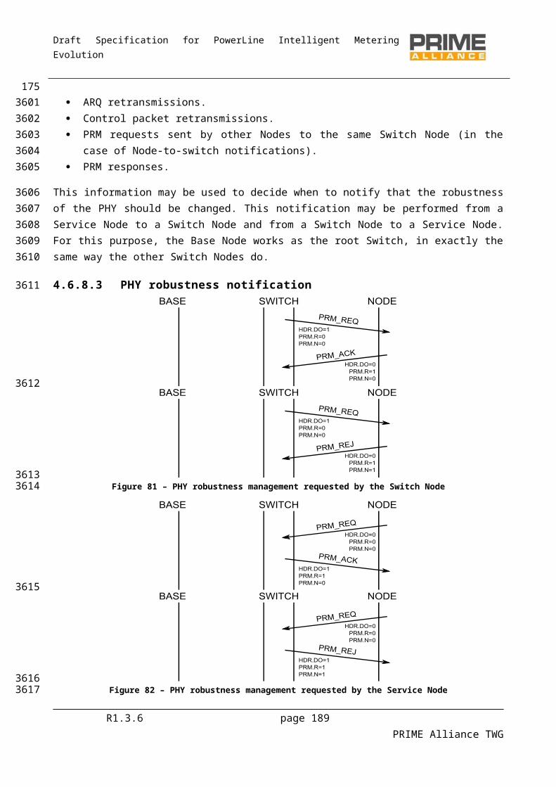
Draft Specification for PowerLine Intelligent Metering Evolution
Table 89 shows the connection data sent in response to the connection request.
Table 89 - IPv6 Connection signalling data sent by the responder
Name Length Description
Reserved 6-bits Should be encoded as zero in this version of the convergence layer protocol
Data.HC 2-bit Header Compression negotiated
Data.HC = 0 – No compression requested: NOTE: When stateless address compression is used all nodes shall support it. When the stateless address compression is not used then the node notify by this value, its compression capability. Data.HC = 1 – LOWPAN_NH
Data.HC = 2 – stateful address compression.
Data.HC = 3 – LOWPAN_NH and stateful address compression.
All nodes support stateless address compression.
The next header compression scheme and stateful address compression can only be used when it is supported by both Service Nodes. The responder may only set Data.HC to the same value as that received from the initiator or a value lower than the one received. When the same value is used, it indicates that the requested compression scheme has been negotiated and will be used for the connection. Setting Data.HC to lower value allows the responder to deny the request for that header compression scheme.
5.6.9 Service access point
5.6.9.1 Overview
This section defines the service access point used by the IPv6 layer to communicate with the IPv6 convergence layer.
5.6.9.2 Opening and closing the convergence layer
The following primitives are used to open and close the convergence layer. The convergence layer may be opened once only. The IPv6 layer may close the convergence layer when the IPv6 interface is brought down. The convergence layer will also close the convergence layer when the underlying MAC connection to the Base Node has been lost.
5.6.9.2.1 CL_IPv6_Establish.request
The CL_IPv6_ESTABLISH.request primitive is passed from the IPv6 layer to the IPv6 convergence layer. It is used when the IPv6 layer brings the interface up.
R1.3.6 page 189 PRIME Alliance TWG
3992
3993
3994
39953996399739983999
4000
4001
40024003
4004
4005400640074008
4009
4010
40114012
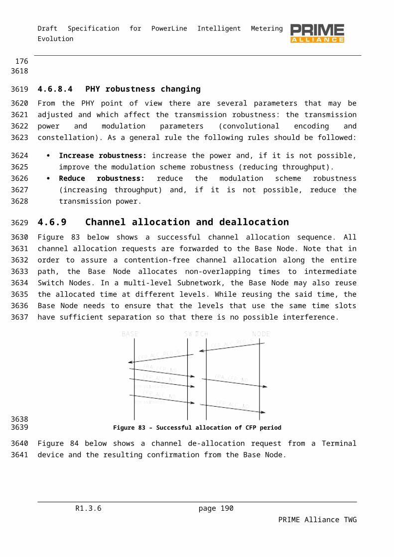
Draft Specification for PowerLine Intelligent Metering Evolution
The semantics of this primitive are as follows:
CL_IPv6_ESTABLISH.request
On receiving this primitive, the convergence layer will form the address resolution connection to the Base Node.
5.6.9.2.2 CL_IPv6_Establish.confirm
The CL_IPv6_ESTABLISH.confirm primitive is passed from the IPv6 convergence layer to the IPv6 layer. It is used to indicate that the convergence layer is ready to access IPv6 packets to be sent to peers.
The semantics of this primitive are as follows:
CL_IPv6_ESTABLISH.confirm
Once the convergence layer has established all the necessary connections and is ready to transmit and receive IPv6 packets, this primitive is passed to the IPv6 layer. If the convergence layer encounters an error while opening, it responds with a CL_IPv6_RELEASE.confirm primitive, rather than a CL_IPv6_ESTABLISH.confirm.
5.6.9.2.3 CL_IPv6_Release.request
The CL_IPv6_RELEASE.request primitive is used by the IPv6 layer when the interface is put down. The convergence layer closes all connections so that no more IPv6 packets are received and all resources are released.
The semantics of this primitive are as follows:
CL_IPv6_RELEASE.request
Once the convergence layer has released all its connections and resources it returns a CL_IPv6_RELEASE.confirm.
5.6.9.2.4 CL_IPv6_Release.confirm
The CL_IPv6_RELEASE.confirm primitive is used by the IPv6 convergence layer to indicate to the IPv6 layer that the convergence layer has been closed. This can be as a result of a CL_IPv6_RELEASE.request primitive, a CL_IPv6_ESTABLISH.request primitive, or because the MAC layer indicates the address resolution connection has been lost, or the Service Node itself is no longer registered.
The semantics of this primitive are as follows:
CL_IPv6_RELEASE.confirmresult
The result parameter has the meanings defined in Table 118.
R1.3.6 page 190 PRIME Alliance TWG
4013
4014
40154016
4017
4018
40194020
4021
4022
4023402440254026
4027
4028
402940304031
4032
4033
40344035
4036
4037
4038403940404041
4042
4043
4044
4045
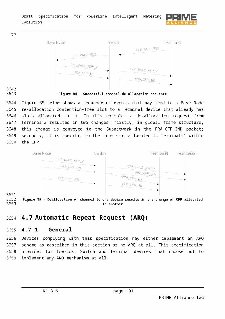
Draft Specification for PowerLine Intelligent Metering Evolution
5.6.9.3 Unicast address management
5.6.9.3.1 General
The primitives defined here are used for address management, i.e. the registration and unregistration of IPv6 addresses associated with this convergence layer.
When there are no IPv6 addresses associated with the convergence layer, the convergence layer will only send and receive multicast packets; unicast packets may not be sent. However, this is sufficient for various address discovery protocols to be used to gain an IPv6 address. Once an IPv6 address has been registered, the IPv6 layer can transmit unicast packets that have a source address equal to one of its registered addresses.
5.6.9.3.2 CL_IPv6_Register.request
This primitive is passed from the IPv6 layer to the IPv6 convergence layer to register an IPv6 address.
The semantics of this primitive are as follows:
CL_IPv6_REGISTER.requestipv6, netmask, gateway
The ipv6 address is the address to be registered.
The netmask is the network mask, used to mask the network number from the address. The netmask is used by the convergence layer to determine whether the packet should deliver directly or the gateway should be used.
The IPv6 address of the gateway, to which packets with destination address that are not in the same subnet as the local address are to be sent.
Once the IPv6 address has been registered to the Base Node, a CL_IPv6_REGISTER.confirm primitive is used. If the registration fails, the CL_IPv6_RELEASE.confirm primitive will be used.
5.6.9.3.3 CL_IPv6_Register.confirm
This primitive is passed from the IPv6 convergence layer to the IPv6 layer to indicate that a registration has been successful.
The semantics of this primitive are as follows:
CL_IPv6_REGISTER.confirmipv6
The ipv6 address is the address that was registered.
Once registration has been completed, the IPv6 layer may send IPv6 packets using this source address.
R1.3.6 page 191 PRIME Alliance TWG
4046
4047
40484049
40504051405240534054
4055
4056
4057
4058
4059
4060
406140624063
40644065
40664067
4068
4069
40704071
4072
4073
4074
4075
4076
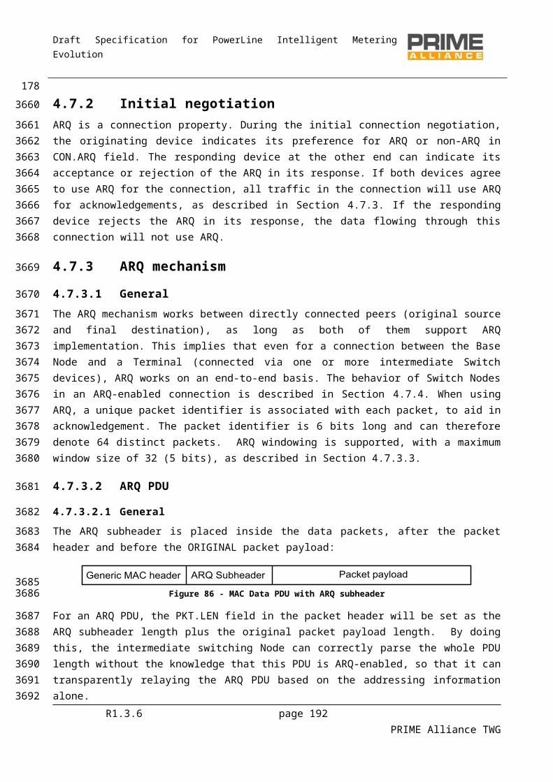
Draft Specification for PowerLine Intelligent Metering Evolution
5.6.9.3.4 CL_IPv6_Unregister.request
This primitive is passed from the IPv6 layer to the IPv6 convergence layer to unregister an IPv6 address.
The semantics of this primitive are as follows:
CL_IPv6_UNREGISTER.requestipv6
The ipv6 address is the address to be unregistered.
Once the IPv6 address has been unregistered to the Base Node, a CL_IPv6_UNREGISTER.confirm primitive is used. If the registration fails, the CL_IPv6_RELEASE.confirm primitive will be used.
5.6.9.3.5 Unregister.confirm
This primitive is passed from the IPv6 convergence layer to the IPv6 layer to indicate that an unregistration has been successful.
The semantics of this primitive are as follows:
CL_IPv6_UNREGISTER.confirmipv6
The IPv6 address is the address that was unregistered.
Once unregistration has been completed, the IPv6 layer may not send IPv6 packets using this source address.
5.6.9.4 Multicast group management
5.6.9.4.1 General
This section describes the primitives used to manage multicast groups.
5.6.9.4.2 CL_IPv6_MUL_Join.request
This primitive is passed from the IPv6 layer to the IPv6 convergence layer. It contains an IPv6 multicast address that is to be joined.
The semantics of this primitive are as follows:
CL_IPv6_MUL_JOIN.requestIPv6
The IPv6 address is the IPv6 multicast group that is to be joined.
When the convergence layer receives this primitive, it will arrange for IP packets sent to this group to be multicast in the PRIME network and receive packets using this address to be passed to the IPv6 stack. If the convergence layer cannot join the group, it uses the CL_IPv6_MUL_LEAVE.confirm primitive. Otherwise the CL_IPv6_MUL_JOIN.confirm primitive is used to indicate success.
R1.3.6 page 192 PRIME Alliance TWG
4077
4078
4079
4080
4081
40824083
4084
4085
40864087
4088
4089
4090
40914092
4093
4094
4095
4096
4097
40984099
4100
4101
4102
4103410441054106
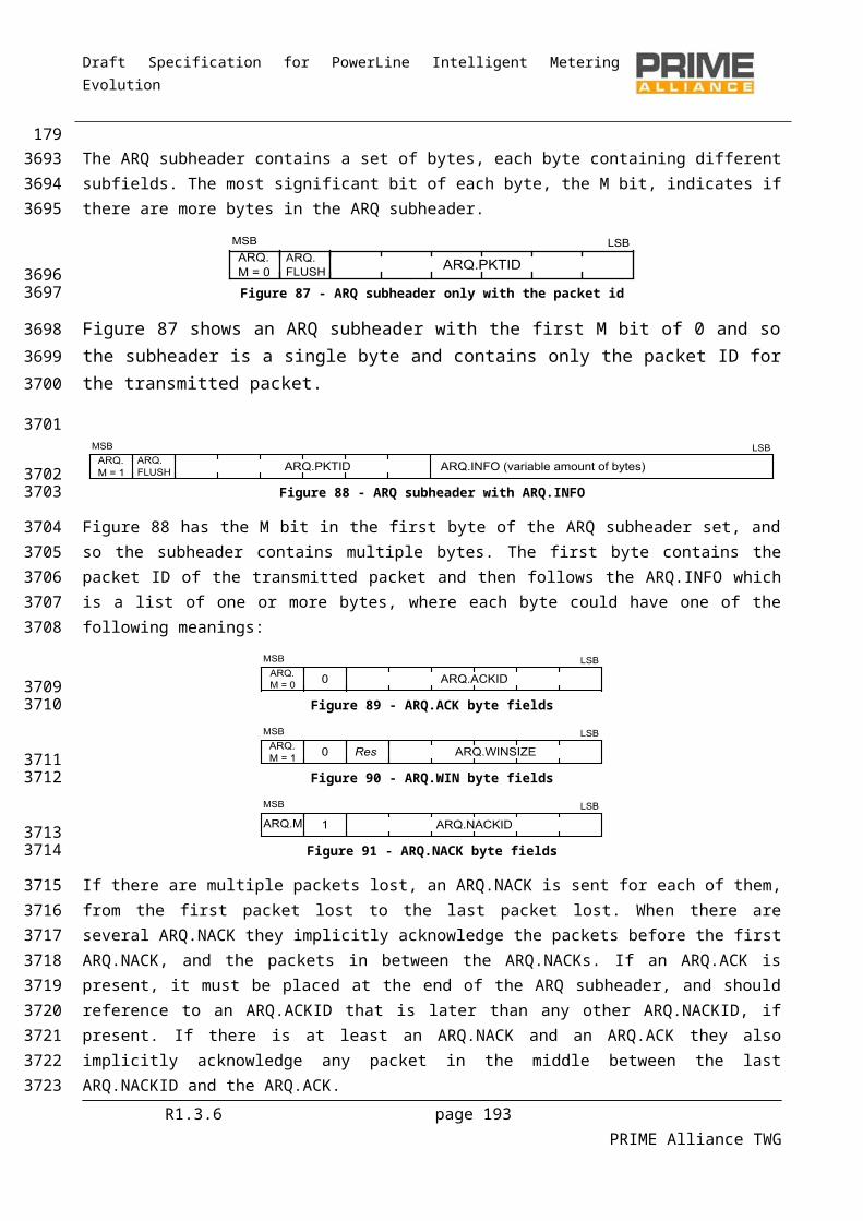
Draft Specification for PowerLine Intelligent Metering Evolution
5.6.9.4.3 CL_IPv6_MUL_Join.confirm
This primitive is passed from the IPv6 convergence layer to the IPv6. It contains a result status and an IPv6 multicast address that was joined.
The semantics of this primitive are as follows:
CL_IPv6_MUL_JOIN.confirmIPv6
The IPv6 address is the IPv6 multicast group that was joined. The convergence layer will start forwarding IPv6 multicast packets for the given multicast group.
5.6.9.4.4 CL_IPv6_MUL_Leave.request
This primitive is passed from the IPv6 layer to the IPv6 convergence layer. It contains an IPv6 multicast address to be left.
The semantics of this primitive are as follows:
CL_IPv6_MUL_LEAVE.requestIPv6
The IPv6 address is the IPv6 multicast group to be left. The convergence layer will stop forwarding IPv6 multicast packets for this group and may leave the PRIME MAC multicast group.
5.6.9.4.5 CL_IPv6_MUL_Leave.confirm
This primitive is passed from the IPv6 convergence layer to the IPv6. It contains a result status and an IPv6 multicast address that was left.
The semantics of this primitive are as follows:
CL_IPv6_MUL_LEAVE.confirmIPv6, Result
The IPv6 address is the IPv6 multicast group that was left. The convergence layer will stop forwarding IPv6 multicast packets for the given multicast group.
The Result takes a value from Table 134.
This primitive can be used by the convergence layer as a result of a CL_IPv6_MUL_JOIN.request, CL_IPv6_MUL_LEAVE.request or because of an error condition resulting in the loss of the PRIME MAC multicast connection.
5.6.9.5 Data transfer
5.6.9.5.1 General
The following primitives are used to send and receive IPv6 packets.
5.6.9.5.2 CL_IPv6_DATA.request
This primitive is passed from the IPv6 layer to the IPv6 convergence layer. It contains one IPv6 packet to be sent.
R1.3.6 page 193 PRIME Alliance TWG
4107
41084109
4110
4111
41124113
4114
41154116
4117
4118
41194120
4121
41224123
4124
4125
41264127
4128
412941304131
4132
4133
4134
4135
4136
41374138
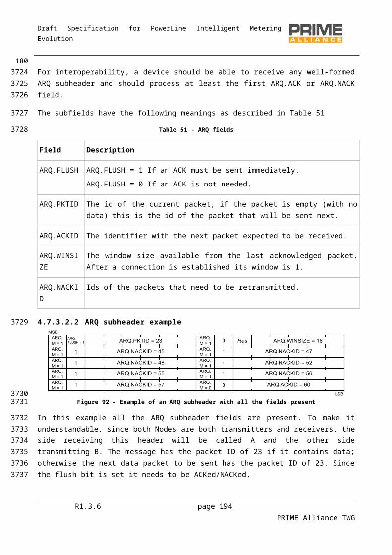
Draft Specification for PowerLine Intelligent Metering Evolution
The semantics of this primitive are as follows:
CL_IPv6_DATA.requestIPv6_PDU
The IPv6_PDU is the IPv6 packet to be sent.
5.6.9.5.3 CL_IPv6_DATA.confirm
This primitive is passed from the IPv6 convergence layer to the IPv6 layer. It contains a status indication and an IPv6 packet that has just been sent.
The semantics of this primitive are as follows:
CL_IPv6_DATA.confirmIPv6_PDU, Result
The IPv6_PDU is the IPv6 packet that was to be sent.
The Result value indicates whether the packet was sent or an error occurred. It takes a value from Table134.
5.6.9.5.4 CL_IPv6_DATA.indicate
This primitive is passed from the IPv6 convergence layer to the IPv6 layer. It contains an IPv6 packet that has just been received.
The semantics of this primitive are as follows:
CL_IPv6_DATA.indicateIPv6_PDU
The IPv6_PDU is the IPv6 packet that was received.
R1.3.6 page 194 PRIME Alliance TWG
4139
4140
4141
4142
41434144
4145
4146
4147
41484149
4150
41514152
4153
4154
4155
4156
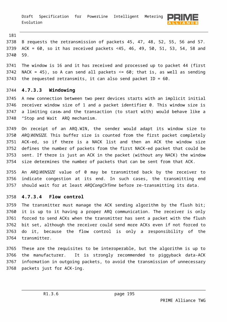
Draft Specification for PowerLine Intelligent Metering Evolution
6 Management plane
6.1 IntroductionThis chapter specifies the Management Plane functionality. The picture below highlights the position of Management Plan in overall protocol architecture.
Convergence Layer
Service Specific Convergence Sublayer (SSCS)
IPv4SSCS
IPv6SSCS
IEC - 432SSCS
NULLSSCS
“New Protocol”SSCS
Common Part Convergence Sublayer (CPCS)
Segmentation and Reassembly (SAR)
MAC Layer MAC PIB
PHY Layer PHY PIB
Aplications
#1 #2 Firmware Upgrade...
Managem
ent Plane
Figure 100 - Management plane. Introduction.
All nodes shall implement the management plane functionality enumerated in this section. Management plane enables a local or remote control entity to perform actions on a Node.
Present version of this specification enumerates management plane functions for Node management and firmware upgrade. Future versions may include additional management functions.
To enable access to management functions on a Service Node, Base Node shall open a management connection after successful completion of registration (refer to 6.4)
The Base Node may open such a connection either immediately on successful registration or sometime later.
Unicast management connection shall be identified with CON.TYPE = TYPE_CL_MGMT. Multicast management connections can also exist. At the time of writing of this document, multicast
management connection shall only be used for firmware upgrade. There shall be no broadcast management connection. In case Service Node supports ARQ connections, the Base Node shall preferentially try to open an
ARQ connection for management functions. Management plane functions shall use NULL SSCS as specified in section 5.3
R1.3.6 page 195 PRIME Alliance TWG
4157
4158
41594160
4161
4162
41634164
41654166
41674168416941704171417241734174417541764177
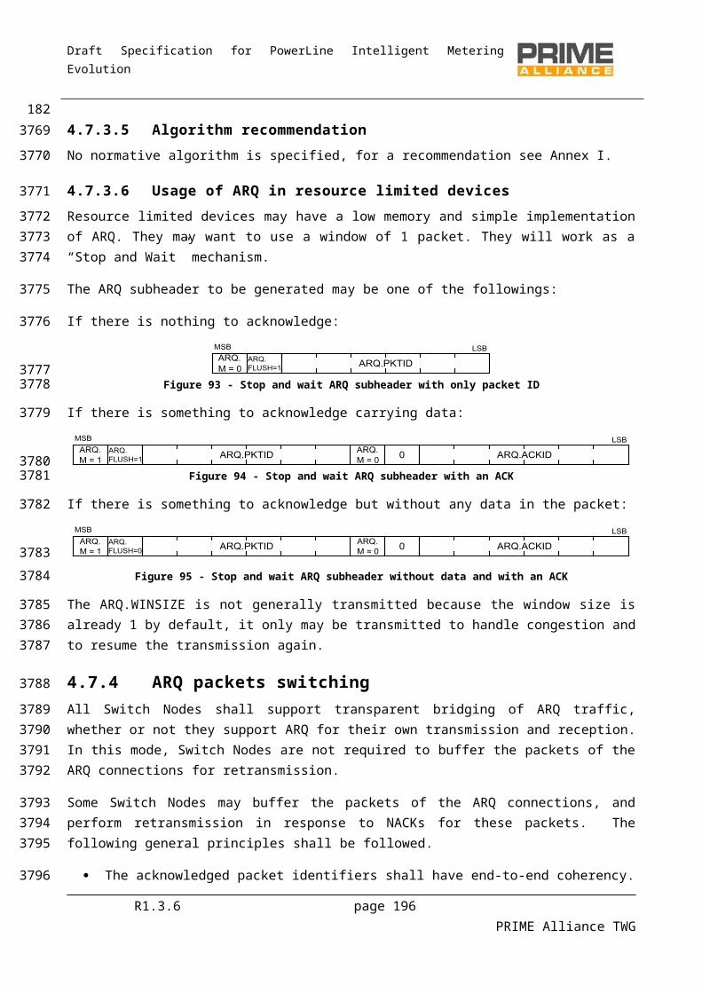
Draft Specification for PowerLine Intelligent Metering Evolution
6.2 Node management
6.2.1 GeneralNode management is accomplished through a set of attributes. Attributes are defined for both PHY and MAC layers. The set of these management attributes is called PLC Information Base (PIB). Some attributes are read-only while others are read-write.
PIB Attribute identifiers are 16 bit values. This allows for up to 65535 PIB Attributes to be specified.
PIB Attribute identifier values from 0 to 32767 are open to be standardized. No proprietary attributes may have identifiers in this range.
Values in the range 32768 to 65535 are open for vendor specific usage.
PIB Attributes identifiers in standard range (0 to 32767) that are not specified in this version are reserved for future use.
Note: PIB attribute tables below indicate type of each attribute. For integer types the size of the integer has been specified in bits. An implementation may use a larger integer for an attribute; however, it must not use a smaller size.
6.2.2 PHY PIB attributes
6.2.2.1 General
The PHY layer implementation in each device may optionally maintain a set of attributes which provide detailed information about its working. The PHY layer attributes are part of the PLC Information Base (PIB).
6.2.2.2 Statistical attributes
The PHY may provide statistical information for management purposes. Next table lists the statistics that PHY should make available to management entities across the PLME_GET primitive. The Id field in this table is the service parameter of the PLME_GET primitive specified in section 3.10.4.
Table 90 - PHY read-only variables that provide statistical information
Attribute Name Size (in bits)
Id Description
phyStatsCRCIncorrectCount 16 0x00A0 Number of bursts received on the PHY layer for which the CRC was incorrect.
phyStatsCRCFailCount 16 0x00A1 Number of bursts received on the PHY layer for which the CRC was correct, but the Protocol field of PHY header had an invalid value. This count would reflect number of times corrupt data was received and the CRC calculation failed to detect it.
phyStatsTxDropCount 16 0x00A2 Number of times when PHY layer received new data to transmit (PHY_DATA.request) and had to
R1.3.6 page 196 PRIME Alliance TWG
4178
4179
418041814182
4183
418441854186
41874188
418941904191
4192
4193
41944195
4196
419741984199
4200

Draft Specification for PowerLine Intelligent Metering Evolution
either overwrite on existing data in its transmit queue or drop the data in new request due to full queue.
phyStatsRxDropCount 16 0x00A3 Number of times when PHY layer received new data on the channel and had to either overwrite on existing data in its receive queue or drop the newly received data due to full queue.
phyStatsRxTotalCount 32 0x00A4 Total number of PPDUs correctly decoded. Useful for PHY layer test cases, to estimate the FER.
phyStatsBlkAvgEvm 16 0x00A5 Exponential moving average of the EVM over the past 16 PPDUs, as returned by the PHY_SNR primitive. Note that the PHY_SNR primitive returns a 3-bit number in dB scale. So first each 3-bit dB number is converted to linear scale (number k goes to 2^(k/2)), yielding a 7 bit number with 3 fractional bits. The result is just accumulated over 16 PPDUs and reported.
phyEmaSmoothing 8 0x00A8 Smoothing factor divider for values that are updated as exponential moving average (EMA). Next value is
Vnext = S*NewSample+(1–S)*Vprev
Where
S=1/(2^phyEMASmoothing).
6.2.2.3 Implementation attributes
It is possible to implement PHY functions conforming to this specification in multiple ways. The multiple implementation options provide some degree of unpredictability for MAC layers. PHY implementations may optionally provide specific information on parameters which are of interest to MAC across the PLME_GET primitive. A list of such parameters which maybe queried across the PLME_GET primitives by MAC is provided in Table 91 - All of the attributes listed in Table 91 - are implementation constants and shall not be changed.
Table 91 - PHY read-only parameters, providing information on specific implementation
Attribute Name Size (in bits)
Id Description
phyTxQueueLen 10 0x00B0 Number of concurrent MPDUs that the PHY transmit
R1.3.6 page 197 PRIME Alliance TWG
4201
420242034204420542064207
4208
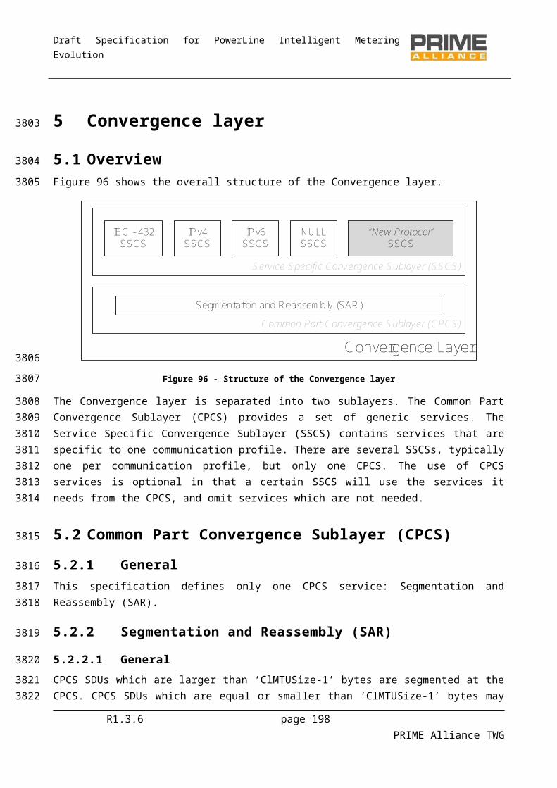
Draft Specification for PowerLine Intelligent Metering Evolution
buffers can hold.
phyRxQueueLen 10 0x00B1 Number of concurrent MPDUs that the PHY receive buffers can hold.
phyTxProcessingDelay 20 0x00B2 Time elapsed from the instance when data is received on MAC-PHY communication interface to the time when it is put on the physical channel. This shall not include communication delay over the MAC-PHY interface.
Value of this attribute is in unit of microseconds.
phyRxProcessingDelay 20 0x00B3 Time elapsed from the instance when data is received on physical channel to the time when it is made available to MAC across the MAC-PHY communication interface. This shall not include communication delay over the MAC-PHY interface.
Value of this attribute is in unit of microseconds.
phyAgcMinGain 8 0x00B4 Minimum gain for the AGC <= 0dB.
phyAgcStepValue 3 0x00B5 Distance between steps in dB <= 6dB.
phyAgcStepNumber 8 0x00B6 Number of steps so that phyAgcMinGain +( (phyAgcStepNumber – 1) * phyAgcStepValue) >= 21dB.
6.2.3 MAC PIB attributes
6.2.3.1 General
Note: Note that the “M”(Mandatory) column in the tables below specifies if the PIB attributes are mandatory for all devices (both Service Node and Base Node, specified as “All”), only for Service Nodes (“SN”), only for Base Nodes (“BN”) or not mandatory at all (“No”).
6.2.3.2 MAC variable attributes
MAC PIB variables include the set of PIB attributes that influence the functional behavior of an implementation. These attributes may be defined external to the MAC, typically by the management entity and implementations may allow changes to their values during normal running, i.e. even after the device start-up sequence has been executed.
An external management entity can have access to these attributes through the MLME_GET (4.5.5.7) and MLME_SET (4.5.5.9) set of primitives. The Id field in the following table would be the PIBAttribute that needs to be passed MLME SAP while working on these parameters
R1.3.6 page 198 PRIME Alliance TWG
4209
4210
4211
421242134214
4215
4216421742184219
422042214222
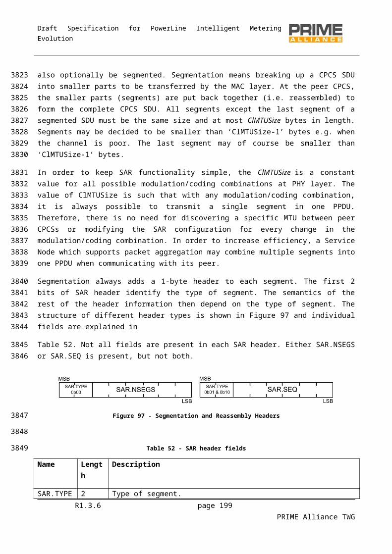
Draft Specification for PowerLine Intelligent Metering Evolution
Table 92 - Table of MAC read-write variables
Attribute Name Id Type M Valid Range
Description Def.
macMinSwitchSearchTime 0x0010 Integer8 No 16 – 32 seconds
Minimum time for which a Service Node in Disconnected status should scan the channel for Beacons before it can broadcast PNPDU.
This attribute is not maintained in Base Nodes.
24
macMaxPromotionPdu 0x0011 Integer8 No 1 – 4 Maximum number of PNPDUs that may be transmitted by a Service Node in a period of macPromotionPduTxPeriod seconds.
This attribute is not maintained in Base Node.
2
macPromotionPduTxPeriod 0x0012 Integer8 No 2 – 8 seconds
Time quantum for limiting a number of PNPDUs transmitted from a Service Node. No more than macMaxPromotionPdu may be transmitted in a period of macPromotionPduTxPeriod seconds.
5
macBeaconsPerFrame 0x0013 Integer8 BN 1 – 5 Maximum number of beacon-slots that may be provisioned in a frame.
This attribute is maintained in Base Nodes.
5
macSCPMaxTxAttempts 0x0014 Integer8 No 2 – 5 Number of times the CSMA algorithm would attempt to transmit requested data when a previous attempt was withheld due to PHY indicating channel busy.
5
R1.3.6 page 199 PRIME Alliance TWG
4223

Draft Specification for PowerLine Intelligent Metering Evolution
Attribute Name Id Type M Valid Range
Description Def.
macCtlReTxTimer 0x0015 Integer8 No 2 – 20 seconds
Number of seconds for which a MAC entity waits for acknowledgement of receipt of MAC control packet from its peer entity. On expiry of this time, the MAC entity may retransmit the MAC control packet.
15
macMaxCtlReTx 0x0018 Integer8 No 3 – 5 Maximum number of times a MAC entity will try to retransmit an unacknowledged MAC control packet. If the retransmit count reaches this maximum, the MAC entity shall abort further attempts to transmit the MAC control packet.
3
macEMASmoothing 0x0019 Integer8 All 0 - 7 Smoothing factor divider for values that are updated as exponential moving average (EMA). Next value is
Vnext = S*NewSample+(1–S)*Vprev
Where
S=1/(2^macEMASmoothing).
3
Table 93 - Table of MAC read-only variables
Attribute Name Id Type M Valid Range
Description Def.
macSCPRBO 0x0016 Integer8 No 1 – 15 symbols
Random backoff period for which an implementation should delay the start of channel-sensing iterations when attempting to transmit data in
-
R1.3.6 page 200 PRIME Alliance TWG
4224
4225
Draft Specification for PowerLine Intelligent Metering Evolution
Attribute Name Id Type M Valid Range
Description Def.
SCP.
This is a ‘read-only’ attribute.
macSCPChSenseCount 0x0017 Integer8 No 2 – 5 Number of times for which an implementation has to perform channel-sensing.
This is a ‘read-only’ attribute.
-
6.2.3.3 Functional attributes
Some PIB attributes belong to the functional behaviour of MAC. They provide information on specific aspects. A management entity can only read their present value using the MLME_GET primitives. The value of these attributes cannot be changed by a management entity through the MLME_SET primitives.
The Id field in the table below would be the PIBAttribute that needs to be passed MLME_GET SAP for accessing the value of these attributes.
Table 94 - Table of MAC read-only variables that provide functional information
Attribute Name Id Type M Valid Range
Description
macLNID 0x0020 Integer16 SN 0 – 16383
LNID allocated to this Node at time of its registration.
MacLSID 0x0021 Integer8 SN 0 – 255
LSID allocated to this Node at time of its promotion. This attribute is not maintained if a Node is in a Terminal functional state.
MacSID 0x0022 Integer8 SN 0 – 255
SID of the Switch Node through which this Node is connected to the Subnetwork. This attribute is not maintained in a Base Node.
MacSNA 0x0023 EUI-48 SN Subnetwork address to which this Node is registered.
The Base Node returns the SNA it is using.
MacState 0x0024 Enumerate SN Present functional state of the Node.
R1.3.6 page 201 PRIME Alliance TWG
4226
422742284229
42304231
4232
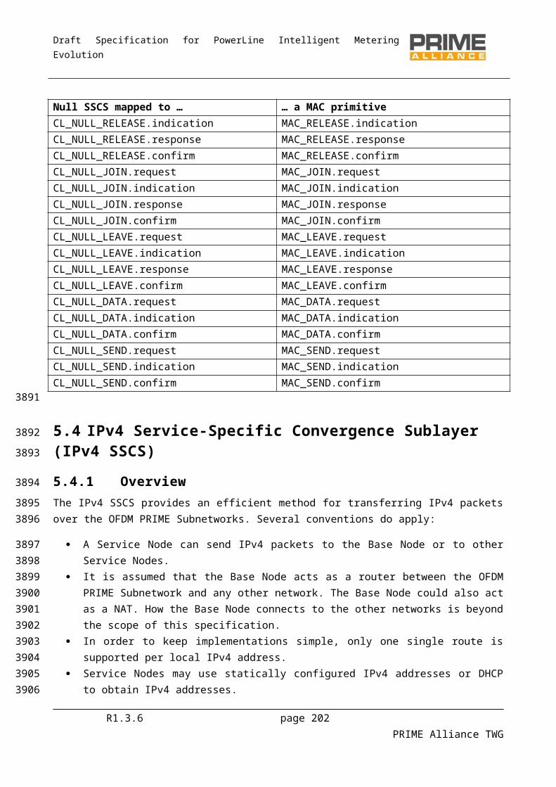
Draft Specification for PowerLine Intelligent Metering Evolution
Attribute Name Id Type M Valid Range
Description
0 DISCONNECTED.
1 TERMINAL.
2 SWITCH.
3 BASE.
MacSCPLength 0x0025 Integer16 SN The SCP length, in symbols, in present frame.
MacNodeHierarchyLevel 0x0026 Integer8 SN 0 – 63 Level of this Node in Subnetwork hierarchy.
MacBeaconSlotCount 0x0027 Integer8 SN 0 – 7 Number of beacon-slots provisioned in present frame structure.
macBeaconRxSlot 0x0028 Integer8 SN 0 – 7 Beacon Slot on which this device’s Switch Node transmits its beacon. This attribute is not maintained in a Base Node.
MacBeaconTxSlot 0x0029 Integer8 SN 0 – 7 Beacon Slot in which this device transmits its beacon. This attribute is not maintained in Service Nodes that are in a Terminal functional state.
MacBeaconRxFrequency 0x002A Integer8 SN 0 – 31 Number of frames between receptions of two successive beacons. A value of 0x0 indicates beacons are received in every frame. This attribute is not maintained in Base Node.
MacBeaconTxFrequency 0x002B Integer8 SN 0 – 31 Number of frames between transmissions of two successive beacons. A value of 0x0 indicates beacons are transmitted in every frame. This attribute is not maintained in Service Nodes that are in a Terminal functional state.
R1.3.6 page 202 PRIME Alliance TWG
Draft Specification for PowerLine Intelligent Metering Evolution
Attribute Name Id Type M Valid Range
Description
MacCapabilities 0x002C Integer16 All Bitmap
Bitmap of MAC capabilities of a given device. This attribute shall be maintained on all devices. Bits in sequence of right-to-left shall have the following meaning:
Bit0: Switch Capable;
Bit1: Packet Aggregation;
Bit2: Contention Free Period;
Bit3: Direct connection;
Bit4: Multicast;
Bit5: PHY Robustness Management;
Bit6: ARQ;
Bit7: Reserved for future use;
Bit8: Direct Connection Switching;
Bit9: Multicast Switching Capability;
Bit10: PHY Robustness Management Switching Capability;
Bit11: ARQ Buffering Switching Capability;
Bits12 to 15: Reserved for future use..
6.2.3.4 Statistical attributes
The MAC layer shall provide statistical information for management purposes. Table 95 lists the statistics MAC shall make available to management entities across the MLME_GET primitive.
The Id field in table below would be the PIBAttribute that needs to be passed MLME_GET SAP for accessing the value of these attributes.
Table 95 - Table of MAC read-only variables that provide statistical information
Attribute Name Id M Type Description
macTxDataPktCount 0x0040 No Integer32 Count of successfully transmitted MSDUs.
R1.3.6 page 203 PRIME Alliance TWG
4233
42344235
42364237
4238

Draft Specification for PowerLine Intelligent Metering Evolution
Attribute Name Id M Type Description
MacRxDataPktCount 0x0041 No Integer32 Count of successfully received MSDUs whose destination address was this Node.
MacTxCtrlPktCount 0x0042 No Integer32 Count of successfully transmitted MAC control packets.
MacRxCtrlPktCount 0x0043 No Integer32 Count of successfully received MAC control packets whose destination address was this Node.
MacCSMAFailCount 0x0044 No Integer32 Count of failed CSMA transmitted attempts.
MacCSMAChBusyCount 0x0045 No Integer32 Count of number of times this Node had to back off SCP transmission due to channel busy state.
6.2.3.5 MAC list attributes
MAC layer shall make certain lists available to the management entity across the MLME_LIST_GET primitive. These lists are given in Table 96. Although a management entity can read each of these lists, it cannot change the contents of any of them.
The Id field in table below would be the PIBListAttribute that needs to be passed MLME_LIST_GET primitive for accessing the value of these attributes.
Table 96 - Table of read-only lists made available by MAC layer through management interface
List Attribute Name Id M Description
macListRegDevices 0x0050 BN List of registered devices. This list is maintained by the Base Node only. Each entry in this list shall comprise the following information.
Entry Element Type Description
regEntryID EUI-48 EUI-48 of the registered Node.
regEntryLNID Integer16 LNID allocated to this Node.
regEntryState TERMINAL=1, SWITCH=2
Functional state of this Node.
regEntryLSID Integer16 SID allocated to this Node.
R1.3.6 page 204 PRIME Alliance TWG
4239
424042414242
42434244
4245
Draft Specification for PowerLine Intelligent Metering Evolution
List Attribute Name Id M Description
regEntrySID Integer16 SID of Switch through which this Node is connected.
regEntryLevel Interger8 Hierarchy level of this Node.
regEntryTCap Integer8 Bitmap of MAC Capabilities of Terminal functions in this device.
Bits in sequence of right-to-left shall have the following meaning:
Bit0: Switch capable;Bit1: Packet Aggregation;Bit2: Contention Free Period;Bit3: Direct connection;Bit4: Multicast;Bit5: PHY Robustness Management;Bit6: ARQ;Bit7: Reserved for future use.
regEntrySwCap Integer8 Bitmap of MAC Switching capabilities of this device
Bits in sequence of right-to-left shall have the following meaning:
Bit0: Direct Connection Switching Capability;Bit1: Multicast switching;Bit2:PHY Robustness Management Switching Capability;Bit3:ARQ Buffering Switching Capability;Bit4 to 7:Reserved for future use.
R1.3.6 page 205 PRIME Alliance TWG
Draft Specification for PowerLine Intelligent Metering Evolution
List Attribute Name Id M Description
macListActiveConn 0x0051 BN List of active non-direct connections. This list is maintained by the Base Node only.
Entry Element Type Description
connEntrySID Integer16 SID of Switch through which the Service Node is connected.
connEntryLNID Integer16 NID allocated to Service Node.
connEntryLCID Integer8 LCID allocated to this connection.
connEntryID EUI-48 EUI-48 of Service Node.
macListMcastEntries
0x0052 No List of entries in multicast switching table. This list is not maintained by Service Nodes in a Terminal functional state.
Entry Element Type Description
mcastEntryLCID Integer8 LCID of the multicast group.
mcastEntryMembers
Integer16 Number of child Nodes (including the Node itself) that are members of this group.
macListSwitchTable 0x0053 SN List the Switch table. This list is not maintained by Service Nodes in a Terminal functional state.
Entry Element
Type Description
stblEntryLSID Integer16 SID of attached Switch Node.
macListDirectConn 0x0054 No List of direct connections that are active. This list is maintained only in the Base Node.
Entry Element Type Description
dconnEntrySrcSID Integer16 SID of Switch through which the source Service Node is connected.
dconEntrySrcLNID Integer16 NID allocated to the source Service Node.
R1.3.6 page 206 PRIME Alliance TWG
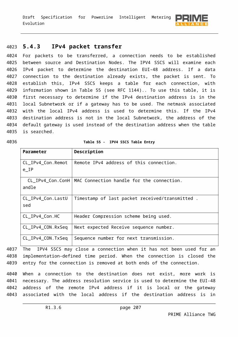
Draft Specification for PowerLine Intelligent Metering Evolution
List Attribute Name Id M Description
dconnEntrySrcLCID Integer8 LCID allocated to this connection at the source.
dconnEntrySrcID EUI-48 EUI-48 of source Service Node.
dconnEntryDstSID Integer16 SID of Switch through which the destination Service Node is connected.
dconnEntryDstLNID
Integer16 NID allocated to the destination Service Node.
dconnEntryDstLCID
Integer8 LCID allocated to this connection at the destination.
dconnEntryDstID EUI-48 EUI-48 of destination Service Node.
dconnEntryDSID Integer16 SID of Switch that is the direct Switch.
dconnEntryDID EUI-48 EUI-48 of direct switch.
macListDirectTable 0x0055 No List the direct Switch table
Entry Element Type Description
dconnEntrySrcSID Integer16 SID of Switch through which the source Service Node is connected.
dconEntrySrcLNID Integer16 NID allocated to the source Service Node.
dconnEntrySrcLCID Integer8 LCID allocated to this connection at the source.
dconnEntryDstSID Integer16 SID of Switch through which the destination Service Node is connected.
R1.3.6 page 207 PRIME Alliance TWG
Draft Specification for PowerLine Intelligent Metering Evolution
List Attribute Name Id M Description
dconnEntryDstLNID
Integer16 NID allocated to the destination Service Node.
dconnEntryDstLCID
Integer8 LCID allocated to this connection at the destination.
dconnEntryDID EUI-48 EUI-48 of direct switch.
macListAvailableSwitches
0x0056 SN List of Switch Nodes whose beacons are received.
Entry Element Type Description
slistEntrySNA EUI-48 EUI-48 of the Subnetwork.
slistEntryLSID Integer16 SID of this Switch.
slistEntryLevel Integer8 Level of this Switch in Subnetwork hierarchy.
slistEntryRxLvl Integer8
EMA
Received signal level for this Switch.
slistEntryRxSNR Integer8 EMA
Signal to Noise Ratio for this Switch.
macListPhyComm 0x0057 All List of PHY communication parameters. This table is maintained in every Node. For Terminal Nodes it contains only one entry for the Switch the Node is connected through. For other Nodes is contains also entries for every directly connected child Node.
Entry Element Type Description
phyCommEUI EUI-48 EUI-48 of the other device.
phyCommTxPwr Integer8 Tx power of GPDU packets send to the device.
phyCommTxCod Integer8 Tx coding of GPDU packets send to the device.
R1.3.6 page 208 PRIME Alliance TWG
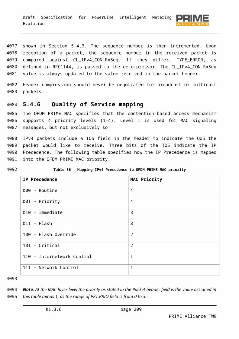
Draft Specification for PowerLine Intelligent Metering Evolution
List Attribute Name Id M Description
phyCommRxCod Integer8 Rx coding of GPDU packets received from the device.
phyCommRxLvlInteger8EMA Rx power level of GPDU
packets received from the device.
phyCommSNRInteger8EMA SNR of GPDU packets
received from the device.
phyCommTxPwrMod Integer8 Number of times the Tx power was modified.
phyCommTxCodMod Integer8 Number of times the Tx coding was modified.
phyCommRxCodMod Integer8 Number of times the Rx coding was modified.
6.2.3.6 Action PIB attributes
Some of the conformance tests require triggering certain actions on Service Nodes. The following table lists the set of action attributes that need to be supported by all implementations.
Table 97 - Action PIB attributes
Attribute Name Id M Size (in bits)
Description
MACActionTxData 0x0060 SN 8 Total number of PPDUs correctly decoded. Useful for PHY layer to estimate FER.
MACActionConnClose 0x0061 SN 8 Trigger to close one of the open connections.
MACActionRegReject 0x0062 SN 8 Trigger to reject incoming registration request.
MACActionProReject 0x0063 SN 8 Trigger to reject incoming promotion request .
MACActionUnregister 0x0064 SN 8 Trigger to unregister from the Subnetwork.
6.2.4 Application PIB attributesThe following PIB attributes are used for general administration and maintenance of a OFDM PRIME compliant device. These attributes do not affect the communication functionality, but enable easier administration.
R1.3.6 page 209 PRIME Alliance TWG
4246
42474248
4249
4250
425142524253
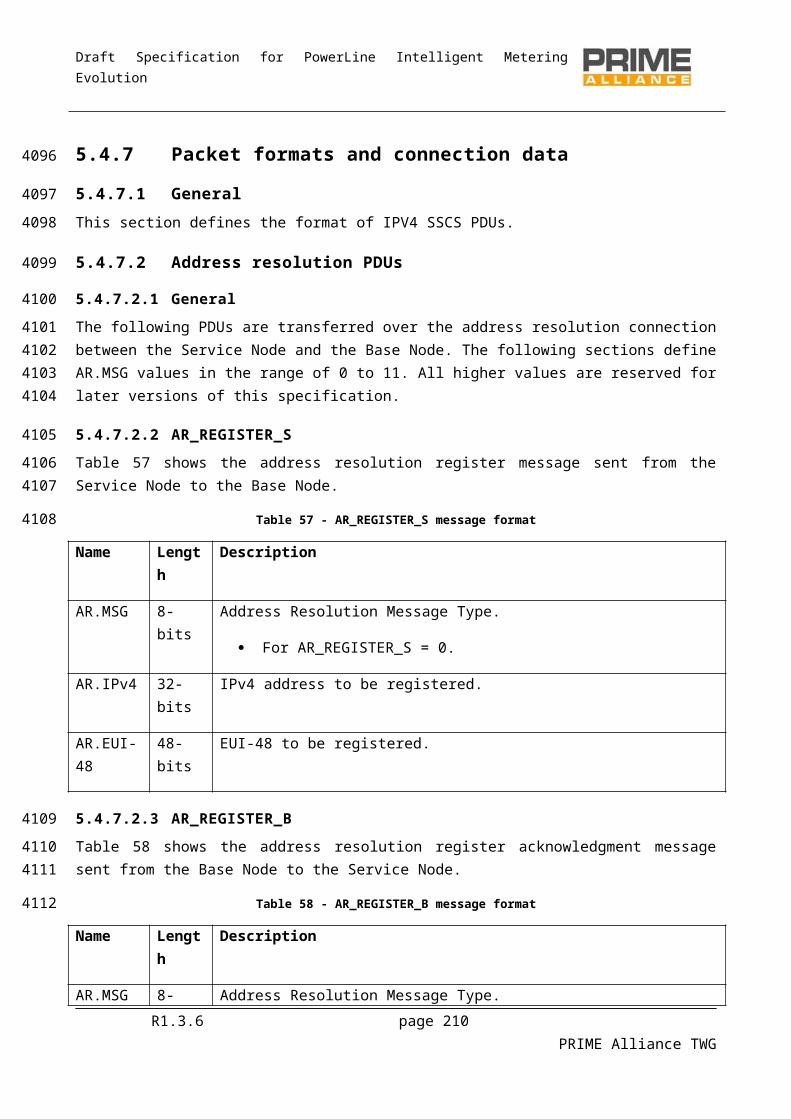
Draft Specification for PowerLine Intelligent Metering Evolution
These attributes shall be supported by both Base Node and Service Node devices.
Table 98 - Applications PIB attributes
Attribute Name Size (in bits)
Id Description
AppFwVersion 128 0x0075 Textual description of firmware version running on device.
AppVendorId 16 0x0076 PRIME Alliance assigned unique vendor identifier.
AppProductId 16 0x0077 Vendor assigned unique identifier for specific product.
6.3 Firmware upgrade
6.3.1 GeneralThe present section specifies firmware upgrade. Devices supporting OFDM PRIME may have several firmware inside them, at least one supporting the Application itself, and the one related to the OFDM PRIME protocol. Although it is possible that the application can perform the firmware upgrade of all the firmware images of the device, for instance DLMS/COSEM image transfer, using COSEM image transfer object, supporting OFDM PRIME firmware upgrade is mandatory in order to process to OFDM PRIME firmware upgrade independently of the application.
6.3.2 Requirements and featuresThis section specifies the firmware upgrade application, which is unique and mandatory for Base Nodes and Service Nodes.
The most important features of the Firmware Upgrade mechanism are listed below. See following chapters for more information. The FU mechanism:
Shall be a part of management plane and therefore use the NULL SSCS, as specified in section 5.3 Is able to work in unicast (default mode) and multicast (optional mode). The control messages are
always sent using unicast connections, whereas data can be transmitted using both unicast and multicast. No broadcast should be used to transmit data.
May change the data packet sizes according to the channel conditions. The packet size will not be changed during the download process.
Is able to request basic information to the Service Nodes at anytime, such as device model, firmware version and FU protocol version.
Shall be abortable at anytime. Shall check the integrity of the downloaded FW after completing the reception. In case of failure, the
firmware upgrade application shall request a new retransmission. The new firmware shall be executed in the Service Nodes only if they are commanded to do so. The
FU application shall have to be able to set the moment when the reset takes place. Must be able to reject the new firmware after a “test” period and switch to the old version. The
duration of this test period has to be fixed by the FU mechanism.
R1.3.6 page 210 PRIME Alliance TWG
4254
4255
4256
4257
425842594260426142624263
4264
42654266
42674268
426942704271427242734274427542764277427842794280428142824283

Draft Specification for PowerLine Intelligent Metering Evolution
6.3.3 General Description
6.3.3.1 General
The Firmware Upgrade mechanism is able to work in unicast and multicast modes. All control messages are sent using unicast connections, whereas the data can be sent via unicast (by default) or multicast (only if supported by the manufacturer). Note that in order to ensure correct reception of the FW when Service Nodes from different vendors are upgraded, data packets shall not be sent via broadcast. Only unicast and multicast are allowed. A Node will reply only to messages sent via unicast. See chapter 6.3.5 for a detailed description of the control and information messages used by the FU mechanism.
The unicast and multicast connections are set up by the Base Node. In case of supporting multicast, the Base Node shall request the Nodes from a specific vendor to join a specific multicast group, which is exclusively created to perform the firmware upgrade and is removed after finishing it.
As said before, it is up to the vendor to use unicast or multicast for transmitting the data. In case of unicast data transmission, please note that the use of ARQ is an optional feature. Some examples showing the traffic between the Base Node and the Service Nodes in unicast and multicast are provided in 6.3.6.
After completing the firmware download, each Service Node is committed by the Base Node to perform an integrity check on it. The firmware download will be restarted if the firmware image results to be corrupt. In other case, the Service Nodes will wait until they are commanded by the Base Node to execute the new firmware.
The FU mechanism can setup the instant when the recently downloaded firmware is executed on the Service Nodes. Thus, the Base Node can choose to restart all Nodes at the same time or in several steps. After restart, each Service Node runs the new firmware for a time period specified by the FU mechanism. If this period expires without receiving any confirmation from the Base Node, or the Base Node decides to abort the upgrade process, the Service Nodes will reject the new firmware and switch to the old version. In any other case (a confirmation message is received) the Service Nodes will consider the new firmware as the only valid version and delete the old one.
This is done in order to leave an “open back-door” in case that the new firmware is defect or corrupt. Please note that the Service Nodes are not allowed to discard any of the stored firmware versions until the final confirmation from the Base Node arrives or until the safety time period expires. The two last firmware upgrade steps explained above are shown in 6.3.5. See chapter 6.3.5.3 for a detailed description of the control messages.
R1.3.6 page 211 PRIME Alliance TWG
4284
4285
428642874288428942904291
429242934294
429542964297
4298429943004301
4302430343044305430643074308
43094310431143124313
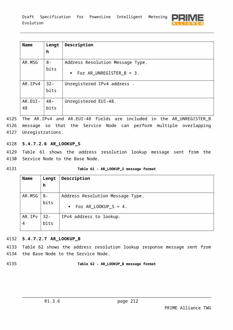
Draft Specification for PowerLine Intelligent Metering Evolution
FU_EXEC_REQ FU_EXEC_REQ
Base Node Service Node 2 (FW version 1)
Service Node 1 (FW version 1)
Firmware Upgrade (versión 1 -> versión 2)
Time specified in FU_EXEC_REQ (RestartTimer)
Time specified in FU_EXEC_REQ (RestartTimer)
Service Node 1 (FW version 2)
Service Node 2 (FW version 2)
restart restart
SafetyTimer
restart
Service Node 2 (FW version 1)
FU_STATE_RSP FU_STATE_RSP
FU_CONFIRM_REQ
FU_STATE_RSP
SafetyTimer
Note: In normal circumstances, both Service Nodes should either accept or reject the new firmware version. Both possibilities are shown above simultaneously for academic purposes.
Figure 101 - Restarting the Nodes and running the new firmware
6.3.3.2 Segmentation
The firmware image is the information to be transferred, in order to process a firmware upgrade. The size of the firmware image will be called “ImageSize”, and is measured in bytes. This image is divided in smaller elements called pages that are easier to be transferred in packets. The “PageSize” may be one of the following: 32 bytes, 64 bytes, 128 bytes or 192 bytes. This implies that the number of pages in a firmware image is calculated by the following formula:
PageCount=⌈ ImageSizePageSize
⌉+1
Every page will have a size specified by PageSize, except the last one that will contain the remaining bytes up to ImageSize.
The PageSize is configured by the Base Node and notified during the initialization of the Firmware Upgrade process, and imposes a condition in the size of the packets being transferred by the protocol.
6.3.4 Firmware upgrade PIB attributesThe following PIB attributes shall be supported by Service Nodes to support the firmware download application.
Table 99 - FU PIB attributes
R1.3.6 page 212 PRIME Alliance TWG
4314
43154316
4317
4318
43194320432143224323
4324
43254326
43274328
4329
43304331
4332
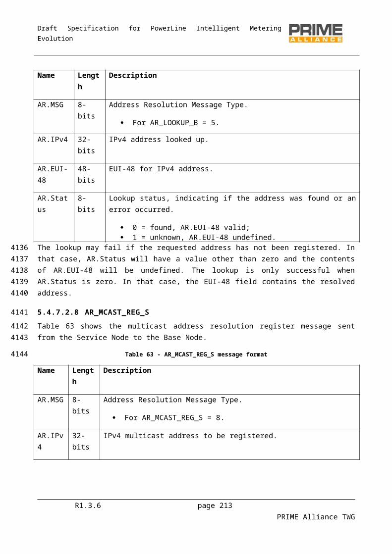
Draft Specification for PowerLine Intelligent Metering Evolution
Attribute Name Size (in bits)
Id Description
AppFwdlRunning 16 0x0070 Indicate if a firmware download is in progress or not.
0 = No firmware download;
1 = Firmware download in progress.
AppFwdlRxPktCount 16 0x0071 Count of firmware download packets that have been received untill the time of query.
6.3.5 State machine
6.3.5.1 General
A Service Node using the Firmware Upgrade service will be in one of five possible states: Idle, Receiving, Complete, Countdown and Upgrade. These states, the events triggering them and the resulting actions/output messages are detailed below.
Table 100 - FU State Machine
FU State Description Event Output (or action to be performed)
Next state
Idle The FU application is doing nothing.
Receive FU_INFO_REQ FU_INFO_RSP. IdleReceive FU_STATE_REQ FU_STATE_RSP (.State = 0). IdleReceive FU_MISS_REQ FU_STATE_RSP (.State = 0). IdleReceive FU_CRC_REQ FU_STATE_RSP (.State = 0). IdleReceive FU_INIT_REQ FU_STATE_RSP (.State = 1). ReceivingReceive FU_DATA (ignore). IdleReceive FU_EXEC_REQ FU_STATE_RSP (.State = 0). IdleReceive FU_CONFIRM_REQ
FU_STATE_RSP (.State = 0). Idle
Receive FU_KILL_REQ FU_STATE_RSP (.State = 0). IdleReceiving The FU application
is receiving the Firmware Image.
Complete FW received and CRC OK
(if CRC of the complete Image is OK, switch to Completewithout sending any additional messages)
Complete
Receive FU_INFO_REQ FU_INFO_RSP. ReceivingReceive FU_STATE_REQ FU_STATE_RSP (.State = 1). ReceivingReceive FU_MISS_REQ FU_MISS_LIST or
FU_MISS_BITMAP.Receiving
Receive FU_CRC_REQ FU_CRC_RSP (FU_STATE_RSP if the
Receiving
R1.3.6 page 213 PRIME Alliance TWG
4333
4334
4335
433643374338
4339
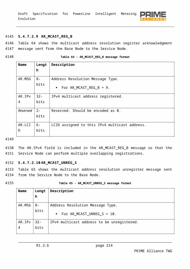
Draft Specification for PowerLine Intelligent Metering Evolution
FU State Description Event Output (or action to be performed)
Next state
Bitmap is not complete)Receive FU_INIT_REQ FU_STATE_RSP (.State = 1) ReceivingReceive FU_DATA (receiving data, normal
behavior).Receiving
Receive FU_EXEC_REQ FU_STATE_RSP (.State = 1). ReceivingReceive FU_CONFIRM_REQ
FU_STATE_RSP (.State = 1). Receiving
Receive FU_KILL_REQ FU_STATE_RSP (.State = 0); (switch to Idle).
Idle
Complete Upgrade completed, image integrity OK, the Service Node is
waiting to reboot with the new FW
version.
Receive FU_INFO_REQ FU_INFO_RSP. CompleteReceive FU_STATE_REQ FU_STATE_RSP (.State = 2). CompleteReceive FU_MISS_REQ FU_STATE_RSP (.State = 2). CompleteReceive FU_CRC_REQ FU_STATE_RSP (.State = 2). CompleteReceive FU_INIT_REQ FU_STATE_RSP (.State = 2). CompleteReceive FU_DATA (ignore). CompleteReceive FU_EXEC_REQ with RestartTimer != 0
FU_STATE_RSP (.State = 3). Countdown
Receive FU_EXEC_REQ with RestartTimer = 0
FU_STATE_RSP (.State = 4). Upgrade
Receive FU_CONFIRM_REQ
FU_STATE_RSP (.State = 2). Complete
Receive FU_KILL_REQ FU_STATE_RSP (.State = 0); (switch to Idle).
Idle
Countdown Waiting until RestartTimer
expires.
RestartTimer expires (switch to Upgrade). UpgradeReceive FU_INFO_REQ FU_INFO_RSP. CountdownReceive FU_STATE_REQ FU_STATE_RSP (.State = 3). CountdownReceive FU_MISS_REQ FU_STATE_RSP (.State = 3). CountdownReceive FU_CRC_REQ FU_STATE_RSP (.State = 3). CountdownReceive FU_INIT_REQ FU_STATE_RSP (.State = 3). CountdownReceive FU_DATA (ignore). CountdownReceive FU_EXEC_REQ with RestartTimer != 0
FU_STATE_RSP (.State = 3); (update RestartTimer and SafetyTimer).
Countdown
Receive FU_EXEC_REQ with RestartTimer = 0
FU_STATE_RSP (.State = 4); (update RestartTimer and SafetyTimer).
Upgrade
Receive FU_CONFIRM_REQ
FU_STATE_RSP (.State = 3). Countdown
Receive FU_KILL_REQ FU_STATE_RSP (.State = 0); (switch to Idle).
Idle
Upgrade The FU mechanism SafetyTimer expires FU_STATE_RSP (.State = 0); Idle
R1.3.6 page 214 PRIME Alliance TWG
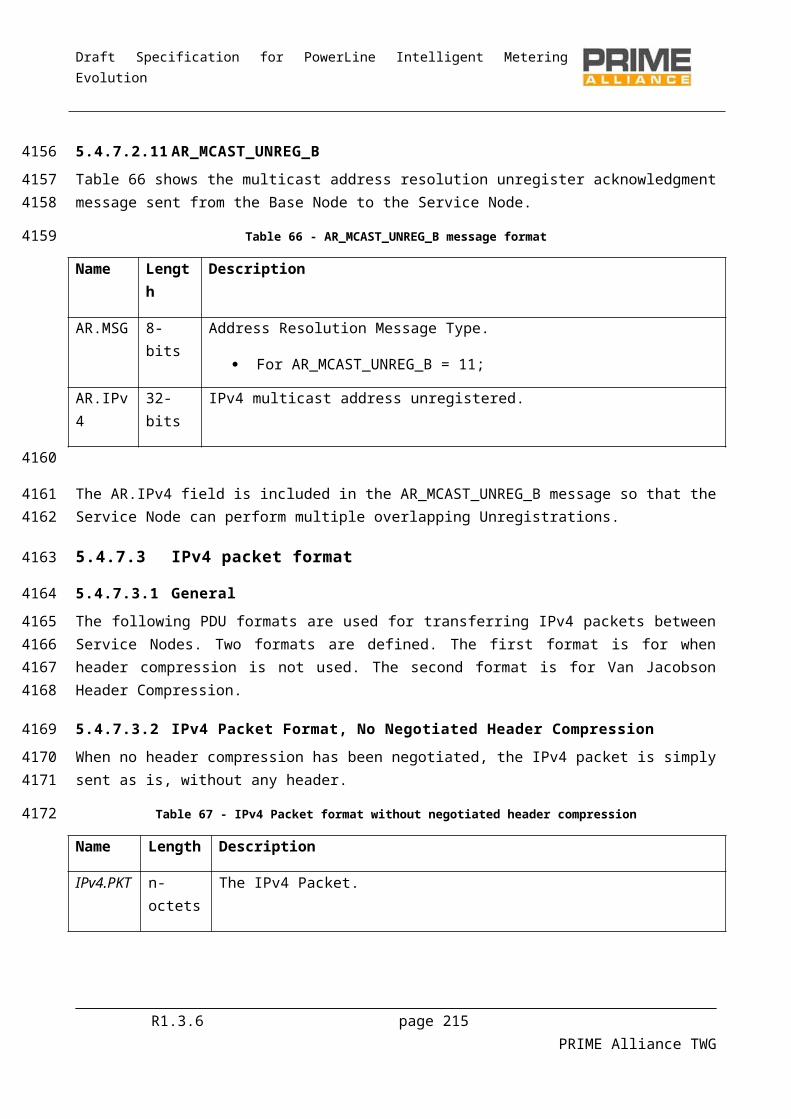
Draft Specification for PowerLine Intelligent Metering Evolution
FU State Description Event Output (or action to be performed)
Next state
reboots using the new FW image and
tests it for SafetyTimer
seconds.
(switch to Idle, FW rejected).
Receive FU_INFO_REQ FU_INFO_RSP. UpgradeReceive FU_STATE_REQ FU_STATE_RSP (.State = 4). UpgradeReceive FU_MISS_REQ FU_STATE_RSP (.State = 4). UpgradeReceive FU_CRC_REQ FU_STATE_RSP (.State = 4). UpgradeReceive FU_INIT_REQ FU_STATE_RSP (.State = 4). UpgradeReceive FU_DATA (ignore). UpgradeReceive FU_EXEC_REQ FU_STATE_RSP (.State = 0). UpgradeReceive FU_CONFIRM_REQ
FU_STATE_RSP (.State = 0); (switch to Idle, FW accepted).
Idle
Receive FU_KILL_REQ FU_STATE_RSP (.State = 0); (switch to Idle, FW rejected).
Idle
R1.3.6 page 215 PRIME Alliance TWG
4340
4341
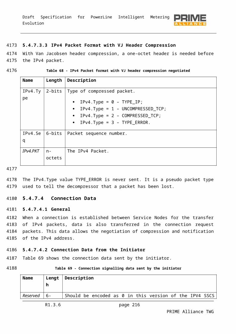
Draft Specification for PowerLine Intelligent Metering Evolution
The state diagram is represented below. Please note that only the most relevant events are shown in the state transitions. See 6.3.5.3 for a detailed description of each state’s behavior and the events and actions related to them. A short description of each state is provided in 6.3.5.2.
RECEIVING
COMPLETECOUNTDOWN
UPGRADE
FU_EXEC_REQ.RestartTimer != 0(FU_STATE_RSP)
Legend:FU_KILL_REQ : BN->SNFU_STATE_RSP: SN->BNreceive internal events[FW i] running FW version
[FW 1]
[FW 2]
[FW 1]
[FW 1][FW 1]
[FW 2]
Figure 102 - Firmware Upgrade mechanism, state diagram
6.3.5.2 State description
6.3.5.2.1 Idle
The Service Nodes are in “Idle” state when they are not performing a firmware upgrade. The reception of a FU_INIT_REQ message is the only event that forces the Service Node to switch to the next state (“Receiving”). FU_KILL_REQ aborts the upgrade process and forces the Service Nodes to switch from any state to “Idle”.
R1.3.6 page 216 PRIME Alliance TWG
434243434344
4345
4346
4347
4348
4349
4350
4351435243534354
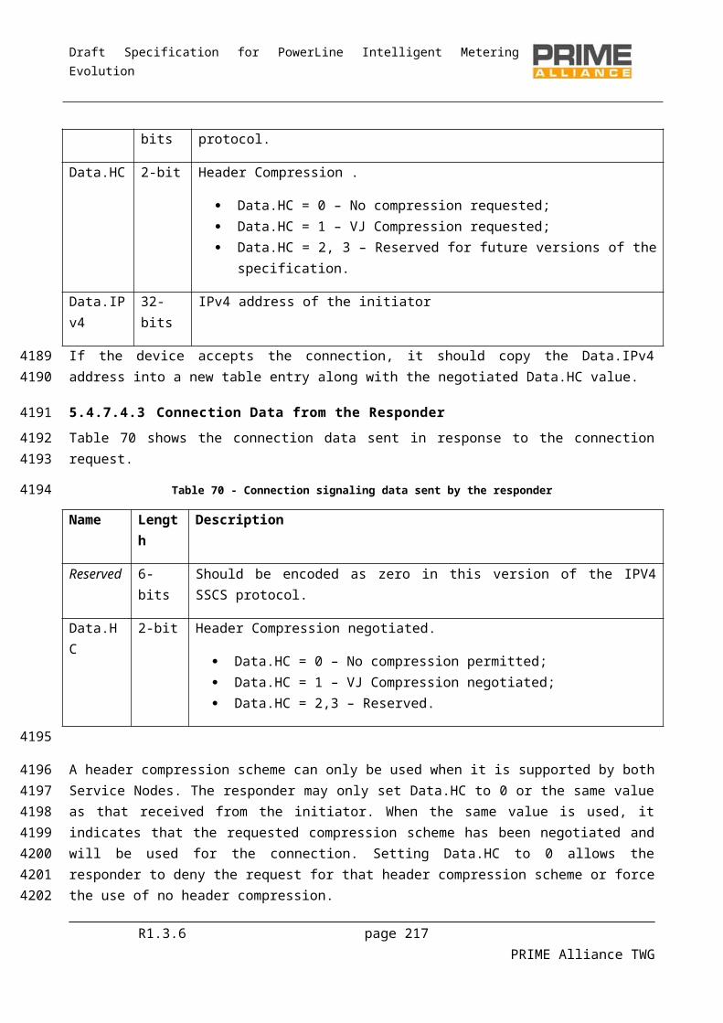
Draft Specification for PowerLine Intelligent Metering Evolution
6.3.5.2.2 Receiving
The Service Nodes receive the firmware image via FU_DATA messages. Once the download is complete, the integrity of the image is checked by the Base Node using FU_CRC_REQ and the Service Node responds with FU_CRC_RSP. This final CRC on the complete FW image is mandatory. If the CRC results to be OK, the Service Node responds with FU_CRC_RSP and then switches to “Complete” state. If the CRC is wrong, the Service Node reports to the Base Node via FU_CRC_RSP, drops the complete FW image, updates the bitmap accordingly and waits for packet retransmission.
Please remember that the Service Node will change from “Receiving” to “Complete” state only if the complete FW has been downloaded and the CRC has been successful.
6.3.5.2.3 Complete
A Service Node in “Complete” state waits until reception of a FU_EXEC_REQ message. The Service Node may switch either to “Countdown” or “Upgrade” depending on the field RestartTimer, which specifies in which instant the Service Node has to reboot using the new firmware. If RestartTimer = 0, the Service Node immediately switches to “Upgrade”; else, the Service Node switches to “Countdown”.
6.3.5.2.4 Countdown
A Service Node in “Countdown” state waits a period of time specified in the RestartTimer field of a previous FU_EXEC_REQ message. When this timer expires, it automatically switches to “Upgrade”.
FU_EXEC_REQ can be used in “Countdown” state to reset RestartTimer and SafetyTimer. In this case, both timers have to be specified in FU_EXEC_REQ because both will be overwritten. Note that it is possible to force the Node to immediately switch from “Countdown” to “Upgrade” state setting RestartTimer to zero.
6.3.5.2.5 Upgrade
A Service Node in “Upgrade” state shall run the new firmware during a time period specified in FU_EXEC_REQ.SafetyTimer. If it does not receive any confirmation at all before this timer expires (or if it receives a FU_KILL_REQ message), the Service Node discards the new FW, reboots with the old version and switches to “Idle” state. In any other case it discards the old FW version and switches to “Idle” state.
6.3.5.3 Control packets
6.3.5.3.1 FU_INIT_REQ
The Base Node sends this packet in order to configure a Service Node for the Firmware Upgrade. If the Service Node is in “Idle” state, it will change its state from “Idle” to “Receiving” and will answer with FU_STATE_RSP. In any other case it will just answer sending FU_STATE_RSP.
The content of FU_INIT_REQ is shown below.
Table 101 - Fields of FU_INIT_REQ
Field Length Description
Type 4 bits 0 = FU_INIT_REQ.
R1.3.6 page 217 PRIME Alliance TWG
4355
435643574358435943604361
43624363
4364
4365436643674368
4369
43704371
437243734374
4375
4376437743784379
4380
4381
438243834384
4385
4386
Draft Specification for PowerLine Intelligent Metering Evolution
Field Length Description
Version 2 bits 0 for this version of the protocol.
PageSize 2 bits 0 for a PageSize=32;
1 for a PageSize=64;
2 for a PageSize=128;
3 for a PageSize=192.
ImageSize 32 bits Size of the Firmware Upgrade image in bytes.
CRC 32 bits CRC of the Firmware Upgrade Image.
The input polynomial M(x) is formed as a polynomial whose coefficients are bits of the data being checked (the first bit to check is the highest order coefficient and the last bit to check is the coefficient of order zero). The Generator polynomial for the CRC is G(x)=x32+x26+x23+x22+x16+x12+x11+x10+x8+x7+x5+x4+x2+x+1. The remainder R(x) is calculated as the remainder from the division of M(x)·x32 by G(x). The coefficients of the remainder will then be the resulting CRC.
6.3.5.3.2 FU_EXEC_REQ
This packet is used by the Base Node to command a Service Node in “Complete” state to restart using the new firmware, once the complete image has been received by the Service Node. FU_EXEC_REQ specifies when the Service Node has to restart and how long the “safety” period shall be, as explained in6.3.5.2.5. Additionally, FU_EXEC_REQ can be used in “Countdown” state to reset the restart and the safety timers.
Depending on the value of RestartTimer, a Service Node in “Complete” state may change either to “Countdown” or to “Upgrade” state. In any case, the Service Node answers with FU_STATE_RSP.
In “Countdown” state, the Base Node can reset RestartTimer and SafetyTimer with a FU_EXEC_REQ message (both timers must be specified in the message because both will be overwritten).
The content of this packet is described below.
Table 102 - Fields of FU_EXEC_REQ
Field Length Description
Type 4 bits 1 = FU_EXEC_REQ.
Version 2 bits 0 for this version of the protocol.
Reserved 2 bits 0 .
RestartTimer 16 bits 0..65536 seconds; time before restarting with new FW.
SafetyTimer 16 bits 0..65536 seconds; time to test the new FW. It starts when the “Upgrade”state is
R1.3.6 page 218 PRIME Alliance TWG
4387
4388438943904391
43924393
43944395
4396
4397
Draft Specification for PowerLine Intelligent Metering Evolution
Field Length Description
entered.
6.3.5.3.3 FU_CONFIRM_REQ
This packet is sent by the Base Node to a Service Node in “Upgrade” state to confirm the current FW. If the Service Node receives this message, it discards the old FW version and switches to “Idle” state. The Service Node answers with FU_STATE_RSP when receiving this message.
In any other state, the Service Node answers with FU_STATE_RSP without performing any additional actions.
This packet contains the fields described below.
Table 103 - Fields of FU_CONFIRM_REQ
Field Length Description
Type 4 bits 2 = FU_CONFIRM_REQ.
Version 2 bits 0 for this version of the protocol.
Reserved 2 bits 0 .
6.3.5.3.4 FU_STATE_REQ
This packet is sent by the Base Node in order to get the Firmware Upgrade state of a Service Node. The Service Node will answer with FU_STATE_RSP.
This packet contains the fields described below.
Table 104 - Fields of FU_STATE_REQ
Field Length Description
Type 4 bits 3 = FU_STATE_REQ.
Version 2 bits 0 for this version of the protocol.
Reserved 2 bits 0.
6.3.5.3.5 FU_KILL_REQ
The Base Node sends this message to terminate the Firmware Upgrade process. A Service Node receiving this message will automatically switch to “Idle” state and optionally delete the downloaded data. The Service Node replies sending FU_STATE_RSP.
The content of this packet is described below.
R1.3.6 page 219 PRIME Alliance TWG
4398
4399
440044014402
44034404
4405
4406
4407
44084409
4410
4411
4412
4413
441444154416
4417
Draft Specification for PowerLine Intelligent Metering Evolution
Table 105 - Fields of FU_KILL_REQ
Field Length Description
Type 4 bits 4 = FU_KILL_REQ.
Version 2 bits 0 for this version of the protocol.
Reserved 2 bits 0.
6.3.5.3.6 FU_STATE_RSP
This packet is sent by the Service Node as an answer to FU_STATE_REQ, FU_KILL_REQ, FU_EXEC_REQ, FU_CONFIRM_REQ or FU_INIT_REQ messages received through the unicast connection. It is used to notify the Firmware Upgrade state in a Service Node.
Additionally, FU_STATE_RSP is used as default response to all events that happen in states where they are not foreseen (e.g. FU_EXEC_REQ in “Receiving” state, FU_INIT_REQ in “Upgrade”...).
This packet contains the fields described below.
Table 106 - Fields of FU_STATE_RSP
Field Length Description
Type 4 bits 5 = FU_STATE_RSP.
Version 2 bits 0 for this version of the protocol.
Reserved 2 bits 0.
State 4 bits 0 for Idle;
1 for Receiving;
2 for Complete;
3 for Countdown;
4 for Upgrade;
5 to 15 reserved for future use.
Reserved 4 bits 0.
CRC 32 bits CRC as the one received in the CRC field of FU_INIT_REQ.
Received 32 bits Number of received pages (this field should only be present if State is Receiving).
R1.3.6 page 220 PRIME Alliance TWG
4418
4419
442044214422
44234424
4425
4426
Draft Specification for PowerLine Intelligent Metering Evolution
6.3.5.3.7 FU_DATA
This packet is sent by the Base Node to transfer a page of the Firmware Image to a Service Node. No answer is expected by the Base Node.
This packet contains the fields described below.
Table 107 - Fields of FU_DATA
Field Length Description
Type 4 bits 6 = FU_DATA.
Version 2 bits 0 for this version of the protocol.
Reserved 2 bits 0.
PageIndex 32 bits Index of the page being transmitted.
Reserved 8 bits Padding byte for 16-bit devices. Set to 0 by default.
Data Variable Data of the page.
The length of this data is PageSize (32, 64, 128 or 192) bytes for every page, except the last one that will have the remaining bytes of the image.
6.3.5.3.8 FU_MISS_REQ
This packet is sent by the Base Node to a Service Node to request information about the pages that are still to be received.
If the Service Node is in “Receiving” state it will answer with a FU_MISS_BITMAP or FU_MISS_LIST message. If the Service Node is in any other state it will answer with a FU_STATE_RSP.
This packet contains the fields described below.
Table 108 - Fields of FU_MISS_REQ
Field Length Description
Type 4 bits 7 = FU_MISS_REQ.
Version 2 bits 0 for this version of the protocol.
Reserved 2 bits 0.
PageIndex 32 bits Starting point to gather information about missing pages.
6.3.5.3.9 FU_MISS_BITMAP
This packet is sent by the Service Node as an answer to a FU_MISS_REQ. It carries the information about the pages that are still to be received.
R1.3.6 page 221 PRIME Alliance TWG
4427
44284429
4430
4431
4432
44334434
44354436
4437
4438
4439
44404441
Draft Specification for PowerLine Intelligent Metering Evolution
This packet will contain the fields described below.
Table 109 - Fields of FU_MISS_BITMAP
Field Length Description
Type 4 bits 8 = FU_MISS_BITMAP.
Version 2 bits 0 for this version of the protocol.
Reserved 2 bits 0.
PageIndex 32 bits Page index of the page represented by the first bit of the bitmap. It should be the same as the PageIndex field in FU_MISS_REQ messages, or a posterior one. If it is posterior, it means that the pages in between are already received. In this case, if all pages after the PageIndex specified in FU_MISS_REQ have been received, the Service Node shall start looking from the beginning (PageIndex = 0).
Bitmap Variable This bitmap contains the information about the status of each page.
The first bit (most significant bit of the first byte) represents the status of the page specified by PageIndex. The next bit represents the status of the PageIndex+1 and so on.
A ‘1’ represents that a page is missing, a ‘0’ represents that the page is already received.
After the bit that represents the last page in the image, it is allowed to overflow including bits that represent the missing status of the page with index zero.
The maximum length of this field is PageSize bytes.
It is up to the Service Node to decide to send this type of packet or a FU_MISS_LIST message. It is usually more efficient to transmit this kind of packets when the number of missing packets is not very low. But it is up to the implementation to transmit one type of packet or the other. The Base Node should understand both.
6.3.5.3.10 FU_MISS_LIST
This packet is sent by the Service Node as an answer to a FU_MISS_REQ. It carries the information about the pages that are still to be received.
This packet will contain the fields described below.
Table 110 - Fields of FU_MISS_LIST
Field Length Description
Type 4 bits 9 = FU_MISS_LIST.
Version 2 bits 0 for this version of the protocol.
R1.3.6 page 222 PRIME Alliance TWG
4442
4443
4444444544464447
4448
44494450
4451
4452
Draft Specification for PowerLine Intelligent Metering Evolution
Field Length Description
Reserved 2 bits 0.
PageIndexList Variable List of pages that are still to be received. Each page is represented by its PageIndex, coded as a 32 bit integer.
These pages should be sorted in ascending order (low to high), being possible to overflow to the PageIndex equal to zero to continue from the beginning.
The first page index should be the same as the PageIndex field in FU_MISS_REQ, or a posterior one. If it is posterior, it means that the pages in between are already received (by posterior it is allowed to overflow to the page index zero, to continue from the beginning).
The maximum length of this field is PageSize bytes.
It is up to the Service Node to decide to transmit this packet type or a FU_MISS_BITMAP message. It is usually more efficient to transmit this kind of packets when the missing packets are very sparse, but it is implementation-dependent to transmit one type of packet or the other. The Base Node should understand both.
6.3.5.3.11 FU_INFO_REQ
This packet is sent by a Base Node to request information from a Service Node, such as manufacturer, device model, firmware version and other parameters specified by the manufacturer. The Service Node will answer with one or more FU_INFO_RSP packets.
This packet contains the fields described below.
Table 111 - Fields of FU_INFO_REQ
Field Length Description
Type 4 bits 10 = FU_INFO_REQ.
Version 2 bits 0 for this version of the protocol.
Reserved 2 bits 0.
InfoIdList Variable List of identifiers with the information to retrieve.
Each identifier is 1 byte long.
The maximum length of this field is 32 bytes.
The following identifiers are defined:
Table 112 - InfoId possible values
R1.3.6 page 223 PRIME Alliance TWG
4453445444554456
4457
445844594460
4461
4462
4463
4464

Draft Specification for PowerLine Intelligent Metering Evolution
InfoId Name Description
0 Manufacturer Universal Identifier of the Manufacturer.
1 Model Model of the product working as Service Node.
2 Firmware Current firmware version being executed.
128-255 Manufacturer specific Range of values that are manufacturer specific.
6.3.5.3.12 FU_INFO_RSP
This packet is sent by a Service Node as a response to a FU_INFO_REQ message from the Base Node. A Service Node may have to send more than one FU_INFO_RSP when replying to a information request by the Base Node.
This packet contains the fields described below.
Table 113 - Fields of FU_INFO_RSP
Field Length Description
Type 4 bits 11 = FU_INFO_RSP.
Version 2 bits 0 for this version of the protocol.
Reserved 2 bits 0.
InfoData 0 – 192 bytes Data with the information requested by the Base Node. It may contain several entries (one for each requested identifier), each entry has a maximum size of 32 bytes. The maximum size of this field is 192 bytes (6 entries).
The InfoData field can contain several entries, the format of each entry is specified below.
Table 114 - Fields of each entry of InfoData in FU_INFO_RSP
Field Length Description
InfoId 8 bits Identifier of the information as specified in 6.3.5.3.11.
Reserved 3 bits 0.
Length 5 bits Length of the Data field (If Length is 0 it means that the specified InfoId is not supported by the specified device).
Data 0 – 30 bytes Data with the information provided by the Service Node.
Its content may depend on the meaning of the InfoId field. No value may be longer than 30 bytes.
R1.3.6 page 224 PRIME Alliance TWG
4465
4466
446744684469
4470
4471
4472
4473
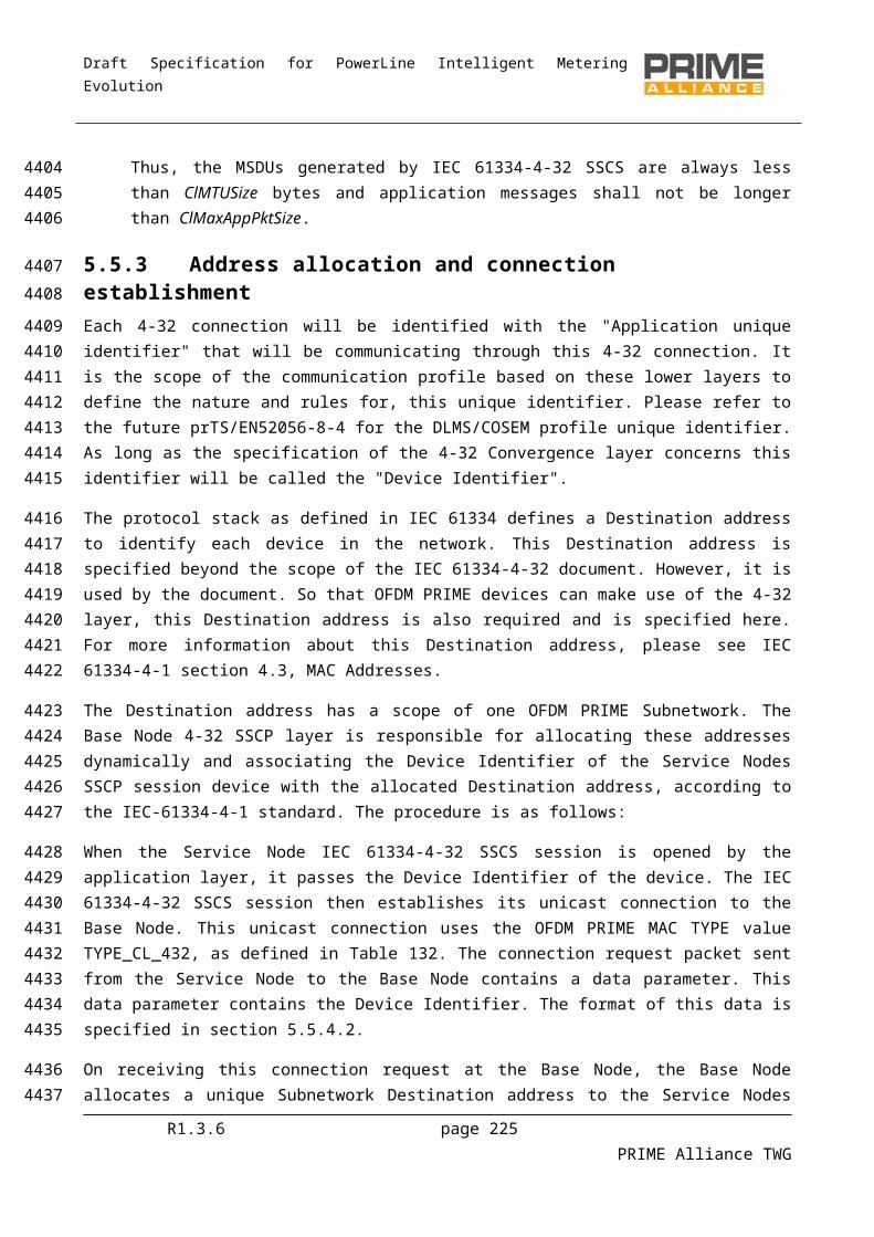
Draft Specification for PowerLine Intelligent Metering Evolution
6.3.5.3.13 FU_CRC_REQ
FU_CRC_REQ is sent by the Base Node to command a Service Node to perform a CRC on the complete firmware image. The CRC on the complete FW image is mandatory. The CRC specified in FU_CRC_REQ.CRC is the same as in FU_INIT_REQ.
The Service Node replies with FU_CRC_RSP if it is in “Receiving” state, in any other case it replies with FU_STATE_RSP. The Base Node shall not send a FU_CRC_REQ if the image download is not complete (that is, the bitmap is not complete). Should the Base Node have an abnormal behavior and send FU_CRC_REQ before completing the FW download, the Service Node would reply with FU_STATE_RSP.
Please note that in “Idle” state, the CRC field from FU_STATE_RSP will be a dummy (because no FU_INIT_REQ has been received yet). The Base Node will ignore this field if the Service Node is in “ Idle” state.
This packet contains the fields described below.
Table 115 - Fields of FU_CRC_REQ
Field Length Description
Type 4 bits 12 = FU_CRC_REQ.
Version 2 bits 0 for this version of the protocol.
Reserved 2 bits 0.
SectionSize 32 bits Size of the Firmware Upgrade Image in bytes.
CRC 32 bits CRC of the Firmware Upgrade Image.
The input polynomial M(x) is formed as a polynomial whose coefficients are bits of the data being checked (the first bit to check is the highest order coefficient and the last bit to check is the coefficient of order zero). The Generator polynomial for the CRC is G(x)=x32+x26+x23+x22+x16+x12+x11+x10+x8+x7+x5+x4+x2+x+1. The remainder R(x) is calculated as the remainder from the division of M(x)·x32 by G(x). The coefficients of the remainder will then be the resulting CRC.
6.3.5.3.14 FU_CRC_RSP
This packet is sent by the Service Node as a response to a FU_CRC_REQ message sent by the Base Node.
This packet contains the fields described below.
Table 116 - Fields of FU_CRC_RSP
Field Length Description
Type 4 bits 13 = FU_CRC_RSP.
R1.3.6 page 225 PRIME Alliance TWG
4474
447544764477
4478447944804481
448244834484
4485
4486
4487
4488
4489
4490
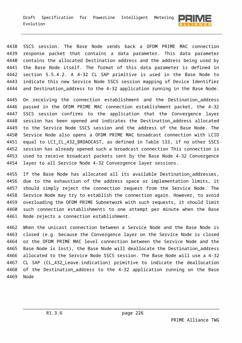
Draft Specification for PowerLine Intelligent Metering Evolution
Field Length Description
Version 2 bits 0 for this version of the protocol.
CRC_Result 1 bit Result of the CRC:
“0” check failed;
“1” check OK.
Reserved 1 bit 0.
R1.3.6 page 226 PRIME Alliance TWG
4491

Draft Specification for PowerLine Intelligent Metering Evolution
6.3.6 ExamplesThe figures below are an example of the traffic generated between the Base Node and the Service Node during the Firmware Upgrade process.
Base Node Service Node A
Get manufacturer, device model and firmware version
Setup Node for Firmware Upgrade
Join multicast group
...
...
CRC of the complete image ok
SN
state
: IDL
ES
N sta
te: R
EC
EIV
ING
SN
state
: C
OM
PLE
TE
Figure 103 - Init Service Node and complete FW image
R1.3.6 page 227 PRIME Alliance TWG
4492
44934494
4495
4496
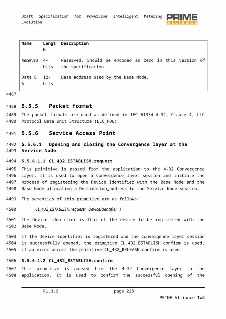
Draft Specification for PowerLine Intelligent Metering Evolution
Above figure shows the initialization of the process, the FW download and the integrity check of the image. In the example above, the downloaded FW image is supposed to be complete before sending the last FU_MISS_REQ. The Base Node sends it to verify its bitmap. In this example, FU_MISS_LIST has an empty PageIndexList field, which means that the FW image is complete.
SN
state
: C
OM
PL
ET
E
Base Node Service Node A Base Node Service Node A
Delayed Firmware restart Immediate Firmware restart
Resta
rtTim
er
Safe
tyTim
er
SN
state
: C
OU
NT
DO
WN
SN
state
: U
PG
RA
DE
SN
state
: IDL
E
SN
state
: C
OM
PL
ET
ES
N sta
te: U
PG
RA
DE
SN
state
: IDL
E
Figure 104 - Execute upgrade and confirm/reject new FW version
Above it is shown how to proceed after completing the FW download. The Base Node commands the Service Node to reboot either immediately (“Immediate Firmware Start”, RestartTimer = 0) or after a defined period of time (“Delayed Firmware start”, RestartTimer != 0). After reboot, the Base Node can either confirm the recently downloaded message sending a FU_CONFIRM_REQ or reject it (sending a FU_KILL_REQ or letting the safety period expire doing nothing).
R1.3.6 page 228 PRIME Alliance TWG
4497449844994500
4501
4502
4503
45044505450645074508
4509
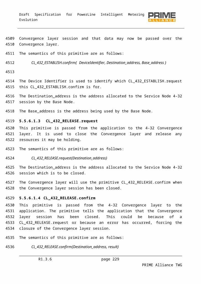
Draft Specification for PowerLine Intelligent Metering Evolution
6.4 Management interface description
6.4.1 GeneralManagement functions defined in earlier sections shall be available over an abstract management interface specified in this section. The management interface can be accessed over diverse media. Each physical media shall specify its own management plane communication profile over which management information is exchanged. It is mandatory for implementations to support PRIME management plane communication profile. All other “management plane communication profiles” are optional and maybe mandated by certain “application profiles” to use in specific cases.
The present version of specifications describes two communication profiles, one of which is over this specification NULL SSCS and other over serial link.
With these two communication profiles, it shall be possible to address the following use-cases:
1. Remote access of management interface over NULL SSCS. This shall enable Base Node's use as a supervisory gateway for all devices in a Subnetwork
2. Local access of management interface (over peripherals like RS232, USBSerial etc) in a Service Node. Local access shall fulfill cases where a coprocessor exists for supervisory control of processor or when manual access is required over local physical interface for maintenance.
Management data comprises of a 2 bytes header followed by payload information corresponding to the type of information carried in message. The header comprises of a 10 bit length field and 6 bit message_id field.
Table 117 - Management data frame fields
Name Length Description
MGMT.LEN 10 bits Length of payload data following the 2 byte header.
LEN=0 implies there is no payload data following this header and the TYPE field contains all required information to perform appropriate action.
NOTE: The length field maybe redundant in some communication profiles (e.g. When transmitted over OFDM PRIME), but is required in others. Therefore for the sake of uniformity, it is always included in management data.
R1.3.6 page 229 PRIME Alliance TWG
4510
4511
451245134514451545164517
45184519
4520
45214522
452345244525
452645274528
4529
4530
4531

Draft Specification for PowerLine Intelligent Metering Evolution
Name Length Description
MGMT.TYPE 6 bits Type of management information carried in corresponding data. Some message_id s have standard semantics which should be respected by all OFDM PRIME compliant devices while others are reserved for local use by vendors.
0x00 – Get PIB attribute query;0x01 – Get PIB attribute response;0x02 – Set PIB attribute command;0x03 – Reset all PIB statistics attributes;0x04 – Reboot destination device;0x05 – Firmware upgrade protocol message;0x06 – 0x0F: Reserved for future use. Vendors should not use these values for local purpose;0x10 – 0x3F : Reserved for vendor specific use.
6.4.2 Payload format of management information
6.4.2.1 Get PIB attribute query
This query is issued by a remote management entity that is interested in knowing values of PIB attributes maintained on a compliant device with this specification.
The payload may comprise of a query on either a single PIB attribute or multiple attributes. For reasons of efficiency queries on multiple PIB attributes maybe aggregated in one single command. Given that the length of a PIB attribute identifier is constant, the number of attributes requested in a single command is derived from the overall MGMT.LEN field in header.
The format of payload information is shown in the following figure.
Fields of a GET request are summarized in table below:
Table 118 - GET PIB Atribubute request fields
Name Length Description
PIB Attribute id 2 bytes 16 bit PIB attribute identifier
Index 1 byte Index of entry to be returned for corresponding PIB Attribute id. This field is only of relevance while returning PIB list attributes.
Index = 0; if PIB Attribute is not a list;Index = 1 to 255; Return list record at given index.
R1.3.6 page 230 PRIME Alliance TWG
4532
4533
45344535
4536453745384539
4540
4541
4542
4543
4544
Draft Specification for PowerLine Intelligent Metering Evolution
6.4.2.2 Get PIB attribute response
This data is sent out from a compliant device of this specification in response to a query of one or more PIB attributes. If a certain queried PIB attribute is not maintained on the device, it shall still respond to the query with value field containing all ‘1s’ in the response.
The format of payload is shown in the following figure.
Figure 105. Get PIB Attribute response.Payload
Fields of a GET request are summarized in table below:
Table 119 - GET PIB Attribute response fields
Name Length Description
PIB Attribute id 2 bytes 16 bit PIB attribute identifier.
Index 1 byte Index of entry returned for corresponding PIB Attribute id. This field is only of relevance while returning PIB list attributes.
index = 0; if PIB Attribute is not a list.
index = 1 to 255; Returned list record is at given index.
PIB Attribute value ‘a’ bytes Values of requested PIB attribute. In case of a list attribute, value shall comprise of entire record corresponding to given index of PIB attribute
Next 1 byte Index of next entry returned for corresponding PIB Attribute id. This field is only of relevance while returning PIB list attributes.
next = 0; if PIB Attribute is not a list or if no records follow the one being returned for a list PIB attribute i.e. given record is last entry in list.
next = 1 to 255; index of next record in list maintained for given PIB attribute.
Response to PIB attribute query can span across several MAC GPDUs. This shall always be the case when an aggregated (comprising of several PIB attributes) PIB query’s response if longer than the maximum segment size allowed to be carried over the NULL SCSS.
6.4.2.3 Set PIB attribute
This management data shall be used to set specific PIB attributes. Such management payload comprises of a 2 byte PIB attribute identifier, followed by the relevant length of PIB attribute information corresponding to that identifier. For reasons of efficiency, it shall be possible to aggregate SET command on several PIB attributes in one GPDU. The format of such an aggregated payload is shown in figure below:
R1.3.6 page 231 PRIME Alliance TWG
4545
454645474548
4549
4550
4551
4552
4553
455445554556
4557
4558455945604561
Draft Specification for PowerLine Intelligent Metering Evolution
For cases where the corresponding PIB attribute is only a trigger (all ACTION PIB attributes), there shall be no associated value and the request data format shall be as shown below:
It is assumed that the management entity sending out this information has already determined if the corresponding attributes are supported at target device. This may be achieved by a previous query and its response.
6.4.2.4 Reset statistics
This command has optional payload. In case there is no associated payload, the receiving device shall reset all of its PIB statistical attributes.
For cases when a remote management entity only intends to perform reset of selective PIB statistical attributes, the payload shall contain a list of attributes that need to be reset. The format shall be the same as shown in Section 6.4.2.1
Since there is no confirmation message going back from the device complying with this specification, the management entity needs to send a follow-up PIB attribute query, in case it wants to confirm successful completion of appropriate action.
6.4.2.5 Reboot device
There is no corresponding payload associated with this command. The command is complete in itself. The receiving compliant device with this specification shall reboot itself on receipt of this message.
It is mandatory for all implementations compliant with this specification to support this command and its corresponding action.
6.4.2.6 Firmware upgrade
The payload in this case shall comprise of firmware upgrade commands and responses described in section 6.3 of the specification.
6.4.3 NULL SSCS communication profileThis communication profile enables exchange of management information described in previous sections over the NULL SSCS.
The management entities at both transmitting and receiving ends are applications making use of the NULL SSCS enumerated in Section 5.3 of this specs. Data is therefore exchanged as MAC Generic PDUs.
R1.3.6 page 232 PRIME Alliance TWG
4562
45634564
4565
456645674568
4569
45704571
457245734574
457545764577
4578
45794580
45814582
4583
45844585
4586
45874588
45894590
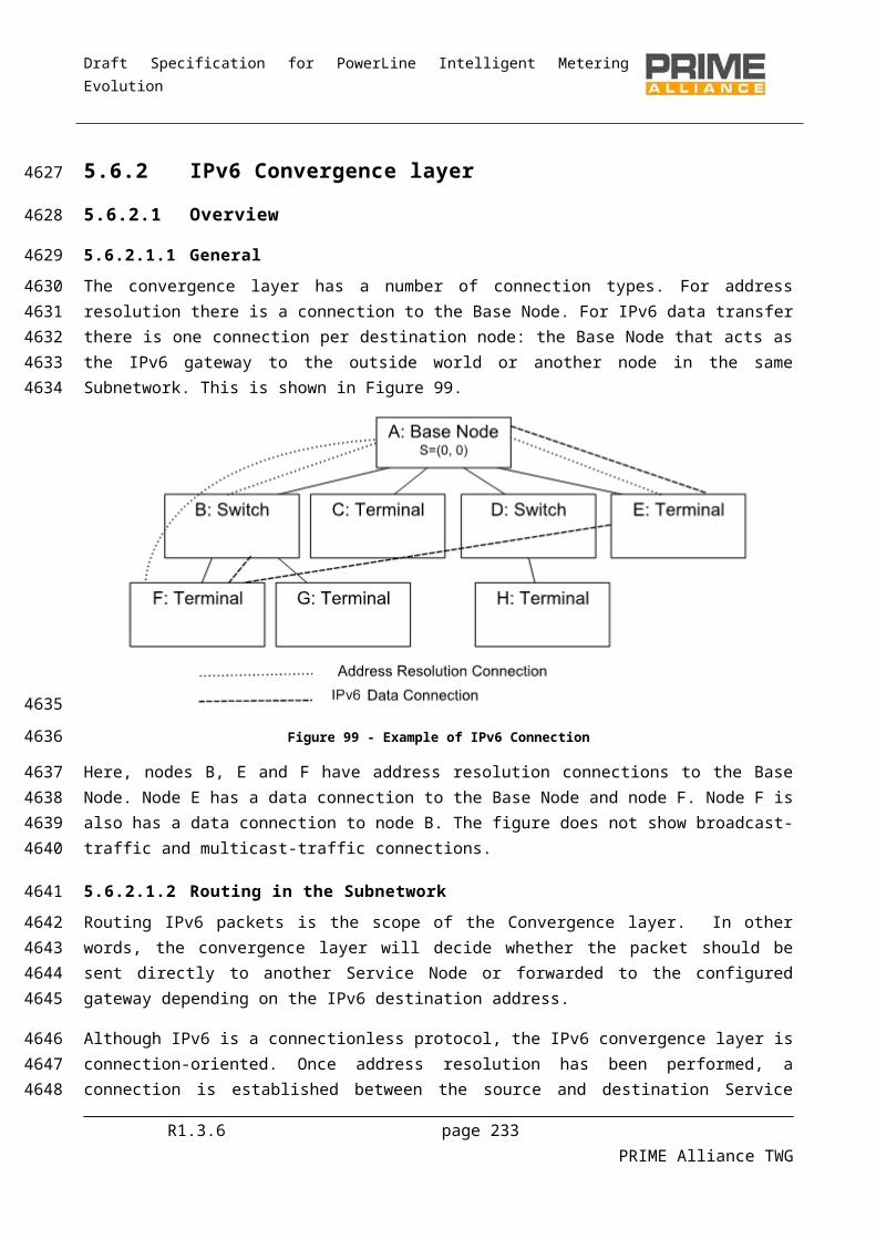
Draft Specification for PowerLine Intelligent Metering Evolution
6.4.4 Serial communication profile
6.4.4.1 Physical layer
The PHY layer maybe any serial link (e.g. RS232, USB Serial). The serial link is required to work 8N1 configuration at one of the following data rates:
9600 bps, 19200 bps, 38400 bps, 57600 bps
6.4.4.2 Data encapsulation for management messages
In order ensure robustness, the stream of data is encapsulated in HDLC-type frames which include a 2 byte header and 4 byte CRC. All data is encapsulated between a starting flag-byte 0x7E and ending flag-byte 0x7E as shown in Figure below:
Figure 106 – Data encapsulations for management messages
If any of the intermediate data characters has the value 0x7E, it is preceded by an escape byte 0x7D, followed by a byte derived from XORing the original character with byte 0x20. The same is done if there is a 0x7D within the character stream. An example of such case is shown here:
Msg to Tx: 0x01 0x02 0x7E 0x03 0x04 0x7D 0x05 0x06
Actual Tx sequence: 0x01 0x02 0x7D 0x5E 0x03 0x04 0x7D 0x5D 0x05 0x06
Escape Escape
sequence sequence
The 32 bit CRC at end of the frame covers both ‘Header’ and ‘Payload’ fields. The CRC is calculated over the original data to be transmitted i.e. before byte stuffing of escape sequences described above is performed. CRC calculation is
The input polynomial M(x) is formed as a polynomial whose coefficients are bits of the data being checked (the first bit to check is the highest order coefficient and the last bit to check is the coefficient of order zero). The Generator polynomial for the CRC is G(x)=x32+x26+x23+x22+x16+x12+x11+x10+x8+x7+x5+x4+x2+x+1. The remainder R(x) is calculated as the remainder from the division of M(x)·x32 by G(x). The coefficients of the remainder will then be the resulting CRC.
6.5 List of mandatory PIB attributes
6.5.1 GeneralPIB attributes listed in this section shall be supported by all implementations. PIB attributes that are not listed in this section are optional and vendors may implement them at their choice. In addition to the PIB
R1.3.6 page 233 PRIME Alliance TWG
4591
4592
45934594
4595
4596
459745984599
4600
4601
460246034604
4605
4606
4607
4608
460946104611
461246134614461546164617
4618
4619
46204621
Draft Specification for PowerLine Intelligent Metering Evolution
attributes, the management command to reboot a certain device (as specified in 6.4.2.5) shall also be universally supported.
6.5.2 Mandatory PIB attributes common to all device types
6.5.2.1 PHY PIB attribute(See Table 90)
Table 120 - PHY PIB common mandatory attributes
Attribute Name Id
phyStatsRxTotalCount 0x00A4
phyStatsBlkAvgEvm 0x00A5
phyEmaSmoothing 0x00A8
6.5.2.2 MAC PIB attributes(See Table 92, Table 94 and Table 95)
Table 121 - MAC PIB comon mandatory attributes
Attribute Name Id
macEMASmoothing 0x0019
Attribute Name Id
MacCapabilities 0x002C
List Attribute Name Id
macListPhyComm 0x0057
6.5.2.3 Application PIB attributes(See Table 98)
Table 122 - Applications PIB common mandotory attributes
Attribute Name Id
AppFwVersion 0x0075
AppVendorId 0x0076
R1.3.6 page 234 PRIME Alliance TWG
46224623
4624
4625
4626
4627
4628
4629
4630
4631
4632
4633
4634
4635
Draft Specification for PowerLine Intelligent Metering Evolution
Attribute Name Id
AppProductId 0x0077
6.5.3 Mandatory Base Node attributes
6.5.3.1 MAC PIB attributes(See Table 92 and Table 96)
Table 123 - MAC PIB Base Node mandatory attributes
Attribute Name Id
macBeaconsPerFrame 0x0013
List Attribute Name Id
macListRegDevices 0x0050
macListActiveConn 0x0051
6.5.4 Mandatory Service Node attributes
6.5.4.1 MAC PIB attributes(See Table 94, Table 96 and Table 97)
Table 124 - MAC PIB Service Node mandatory attributes
Attribute Name Id
macLNID 0x0020
MacLSID 0x0021
MacSID 0x0022
MacSNA 0x0023
MacState 0x0024
MacSCPLength 0x0025
MacNodeHierarchyLevel 0x0026
MacBeaconSlotCount 0x0027
R1.3.6 page 235 PRIME Alliance TWG
4636
4637
4638
4639
4640
4641
4642
4643
4644
4645
Draft Specification for PowerLine Intelligent Metering Evolution
Attribute Name Id
macBeaconRxSlot 0x0028
MacBeaconTxSlot 0x0029
MacBeaconRxFrequency 0x002A
MacBeaconTxFrequency 0x002B
List Attribute Name Id
macListSwitchTable 0x0053
macListAvailableSwitches 0x0056
Attribute Name Id
MACActionTxData 8
MACActionConnClose 8
MACActionRegReject 8
MACActionProReject 8
MACActionUnregister 8
6.5.4.2 Application PIB attributes(See Table 99)
Table 125 - APP PIB Service Node mandatory attributes
Attribute Name Id
AppFwdlRunning 0x0070
AppFwdlRxPktCount 0x0071
R1.3.6 page 236 PRIME Alliance TWG
4646
4647
4648
4649
4650
4651
Draft Specification for PowerLine Intelligent Metering Evolution
Annex A (informative)
Examples of CRC
The table below gives the CRCs calculated for several specified strings.
Table 126 – Examples of CRC calculated for various ASCII strings
String CRC-8
‘T’ 0xab
“THE” 0xa0
0x03, 0x73 0x61
0x01, 0x3f 0xa8
“123456789” 0xf4
R1.3.6 page 237 PRIME Alliance TWG
465246534654
4656
4657
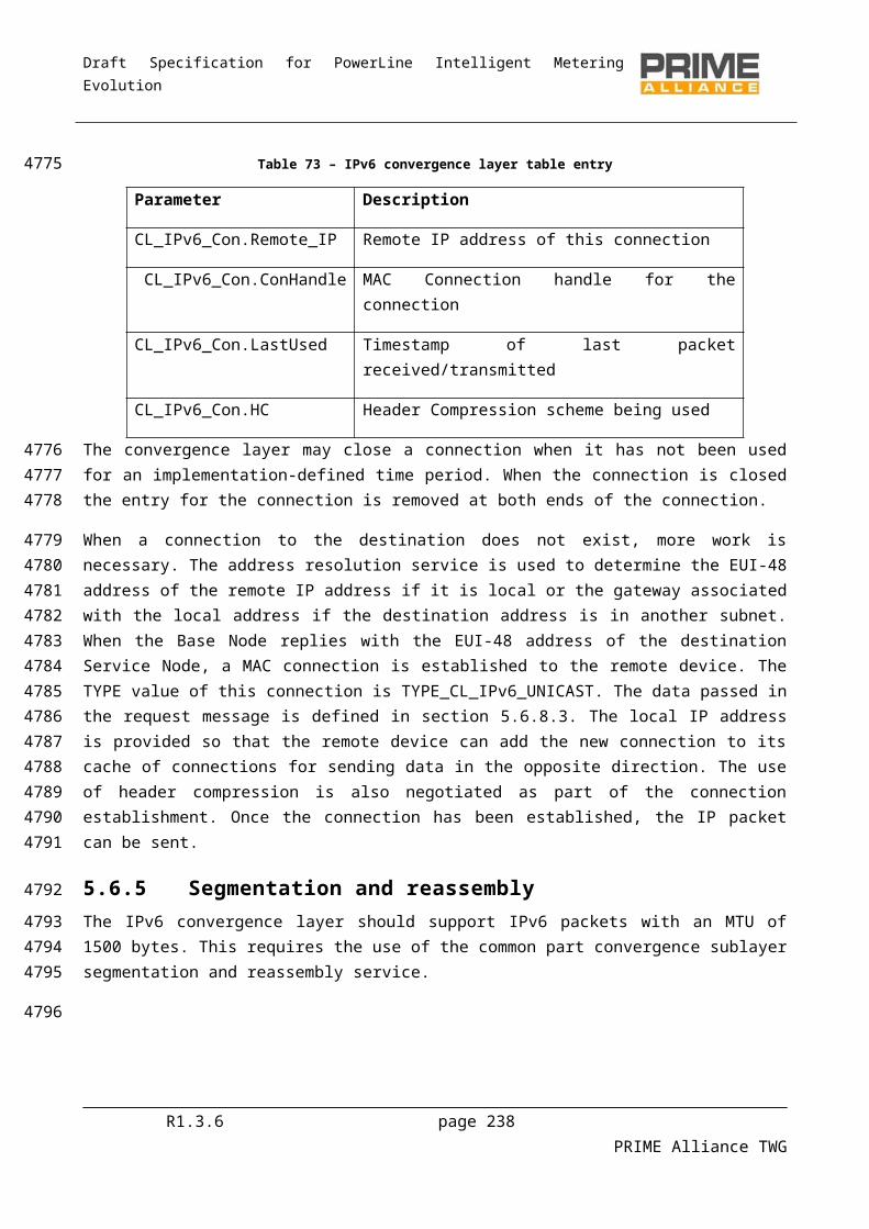
Draft Specification for PowerLine Intelligent Metering Evolution
Annex B (normative)
EVM calculation
This annex describes calculation of the EVM by a reference receiver, assuming accurate synchronization and FFT window placement. Let
rki ;k=1,2 ,. . , 97 denotes the FFT output for symbol i and k are the frequency tones.
Δbk∈ 0,1 ,. .. ,M−1 represents the decision on the received information symbol coded in the phase increment.
M = 2, 4, or 8 in the case of DBPSK, DQPSK or D8PSK, respectively.
The EVM definition is then given by;
EVM=∑i=1
L
∑k=2
97
(abs (rki −r k−1
i e− ( j∗2∗π / M )×Δbk−1))2
∑i=1
L
∑k=2
97
(abs (r ki ))2
In the above, abs(.) refers to the magnitude of a complex number. L is the number of OFDM symbols in the Payload of the most recently received PPDU, over which the EVM is calculated.
The SNR is then defined as the reciprocal of the EVM above.
R1.3.6 page 238 PRIME Alliance TWG
465846594660
46614662
4663
4664466546664667
4668
4669
46704671
4672
4673
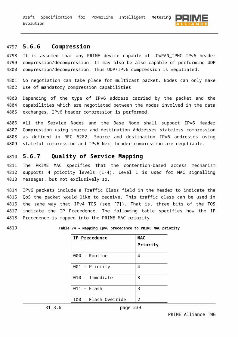
Draft Specification for PowerLine Intelligent Metering Evolution
Annex C (informative)
Interleaving matrixes
Table 127 - Header interleaving matrix.
12 11 10 9 8 7 6 5 4 3 2 124 23 22 21 20 19 18 17 16 15 14 1336 35 34 33 32 31 30 29 28 27 26 2548 47 46 45 44 43 42 41 40 39 38 3760 59 58 57 56 55 54 53 52 51 50 4972 71 70 69 68 67 66 65 64 63 62 6184 83 82 81 80 79 78 77 76 75 74 73
Table 128 - DBPSK(FEC ON) interleaving matrix.
12 11 10 9 8 7 6 5 4 3 2 124 23 22 21 20 19 18 17 16 15 14 1336 35 34 33 32 31 30 29 28 27 26 2548 47 46 45 44 43 42 41 40 39 38 3760 59 58 57 56 55 54 53 52 51 50 4972 71 70 69 68 67 66 65 64 63 62 6184 83 82 81 80 79 78 77 76 75 74 7396 95 94 93 92 91 90 89 88 87 86 85
Table 129 - DQPSK(FEC ON) interleaving matrix.
12 11 10 9 8 7 6 5 4 3 2 124 23 22 21 20 19 18 17 16 15 14 1336 35 34 33 32 31 30 29 28 27 26 2548 47 46 45 44 43 42 41 40 39 38 3760 59 58 57 56 55 54 53 52 51 50 4972 71 70 69 68 67 66 65 64 63 62 6184 83 82 81 80 79 78 77 76 75 74 7396 95 94 93 92 91 90 89 88 87 86 85
108 107 106 105 104 103 102 101 100 99 98 97120 119 118 117 116 115 114 113 112 111 110 109132 131 130 129 128 127 126 125 124 123 122 121144 143 142 141 140 139 138 137 136 135 134 133156 155 154 153 152 151 150 149 148 147 146 145168 167 166 165 164 163 162 161 160 159 158 157180 179 178 177 176 175 174 173 172 171 170 169
R1.3.6 page 239 PRIME Alliance TWG
467446754676
4677
4678
4679
4680
4681
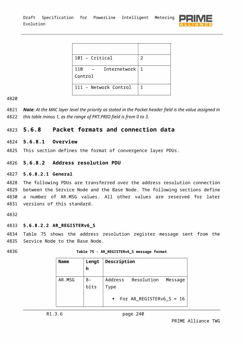
Draft Specification for PowerLine Intelligent Metering Evolution
192 191 190 189 188 187 186 185 184 183 182 181
Table 130 - D8PSK(FEC ON) interleaving matrix.
18 17 16 15 14 13 12 11 10 9 8 7 6 5 4 3 2 136 35 34 33 32 31 30 29 28 27 26 25 24 23 22 21 20 1954 53 52 51 50 49 48 47 46 45 44 43 42 41 40 39 38 3772 71 70 69 68 67 66 65 64 63 62 61 60 59 58 57 56 5590 89 88 87 86 85 84 83 82 81 80 79 78 77 76 75 74 73
108 107 106 105 104 103 102 101 100 99 98 97 96 95 94 93 92 91126 125 124 123 122 121 120 119 118 117 116 115 114 113 112 111 110 109144 143 142 141 140 139 138 137 136 135 134 133 132 131 130 129 128 127162 161 160 159 158 157 156 155 154 153 152 151 150 149 148 147 146 145180 179 178 177 176 175 174 173 172 171 170 169 168 167 166 165 164 163198 197 196 195 194 193 192 191 190 189 188 187 186 185 184 183 182 181216 215 214 213 212 211 210 209 208 207 206 205 204 203 202 201 200 199234 233 232 231 230 229 228 227 226 225 224 223 222 221 220 219 218 217252 251 250 249 248 247 246 245 244 243 242 241 240 239 238 237 236 235270 269 268 267 266 265 264 263 262 261 260 259 258 257 256 255 254 253288 287 286 285 284 283 282 281 280 279 278 277 276 275 274 273 272 271
R1.3.6 page 240 PRIME Alliance TWG
4682
4683
46844685
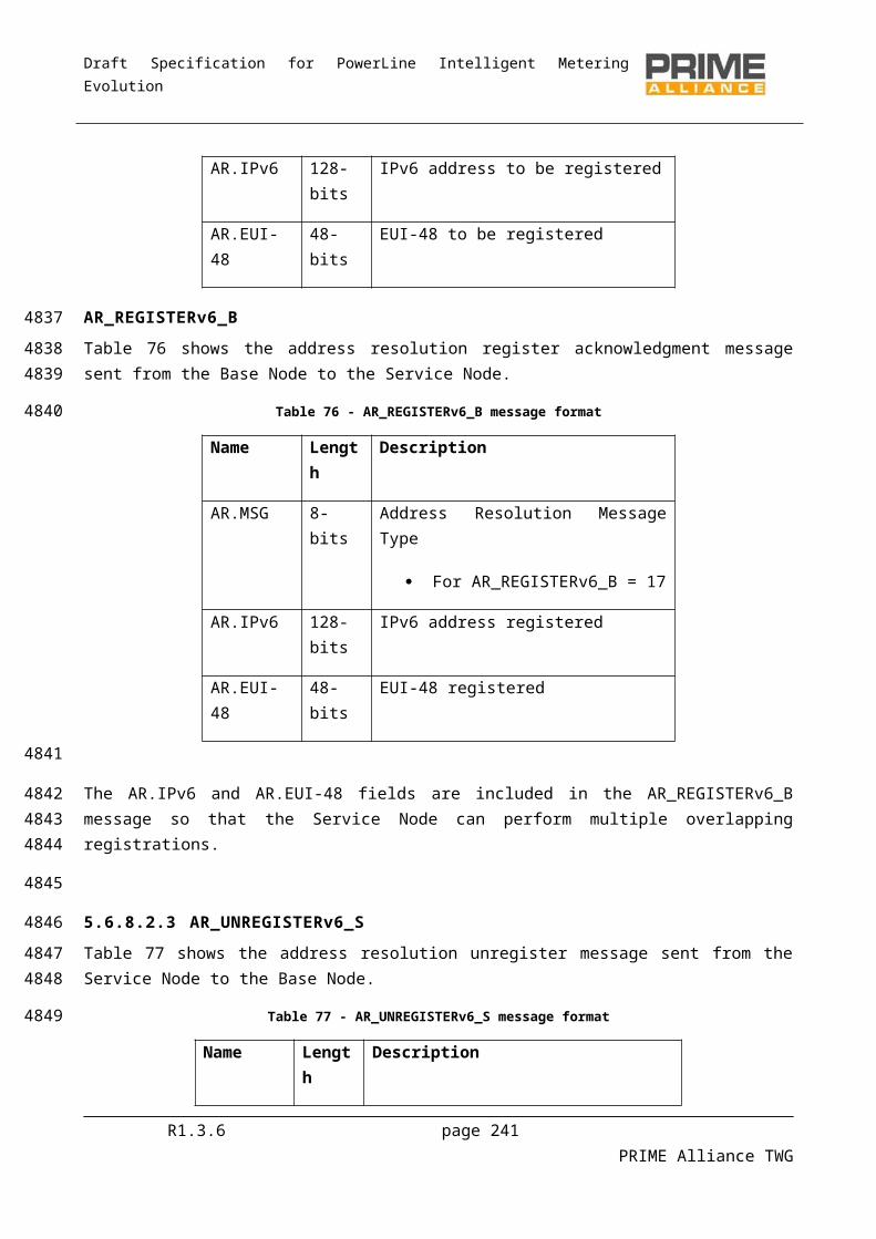
Draft Specification for PowerLine Intelligent Metering Evolution
Annex D (normative)
MAC layer constants
This section defines all the MAC layer constants.
Table 131 - Table of MAC constants
Constant Value Description
MACBeaconLength 4 symbols Length of beacon in symbols.
MACMinSCPLength 64 symbols Minimum length of SCP.
MACPriorityLevels 4 Number of levels of priority supported by the system.
MACCFPMaxAlloc 32 Maximum contention-free periods that may be allocated within a frame.
MACFrameLength 276 symbols Length of a frame in number of symbols.
MACRandSeqChgTime 32767 seconds (approx 9 hours)
Maximum duration of time after which the Base Node should circulate a new random sequence to the Subnetwork for encryption functions.
MACMaxPRNIgnore 3 Maximum number of Promotion-Needed messages a Terminal can ignore.
Nmiss-beacon 5 Number of times a Service Node does not receive an expected beacon before considering its Switch Node as unavailable.
ARQMaxTxCount 5 Maximum Transmission count before declaring a permanent failure.
ARQCongClrTime 2 sec When the receiver has indicated congestion, this time must be waited before retransmitting the data.
ARQMaxCongInd 7 After ARQMaxCongInd consecutive transmissions which failed due to congestion, the connection should be declared permanently dead.
ARQMaxAckHoldTime 7 sec Time the receiver may delay sending an ACK in order to allow consolidated ACKs or piggyback the ACK with a data packet.
R1.3.6 page 241 PRIME Alliance TWG
468646874688
4689
4690
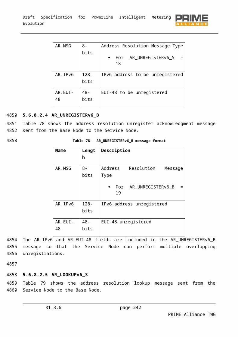
Draft Specification for PowerLine Intelligent Metering Evolution
Annex E (normative)
Convergence layer constants
The following TYPE values are defined for use by Convergence layers from chapter 5.
Table 132 - TYPE value assignments
TYPE Symbolic Name Value
TYPE_CL_IPv4_AR 1
TYPE_CL_IPv4_UNICAST 2
TYPE_CL_432 3
TYPE_CL_MGMT 4
TYPE_CL_IPv6_AR 5
TYPE_CL_IPv6_UNICAST 6
The following LCID values apply for broadcast connections defined by Convergence layers from chapter 5.
Table 133 - LCID value assignments
LCID Symbolic Name Value MAC Scope
LCI_CL_IPv4_BROADCAST 1 Broadcast.
LCI_CL_432_BROADCAST 2 Broadcast.
The following Result values are defined for Convergence layer primitives.
Table 134 - Result values for Convergence layer primitives
Result Description
Success = 0 The SSCS service was successfully performed.
Reject = 1 The SSCS service failed because it was rejected by the base node.
Timeout = 2 A timed out occurs during the SSCS service processing
Not Registered = 6 The service node is not currently registered to a Subnetwork.
R1.3.6 page 242 PRIME Alliance TWG
469146924693
4694
4695
4696
4697
4698
4699
4700
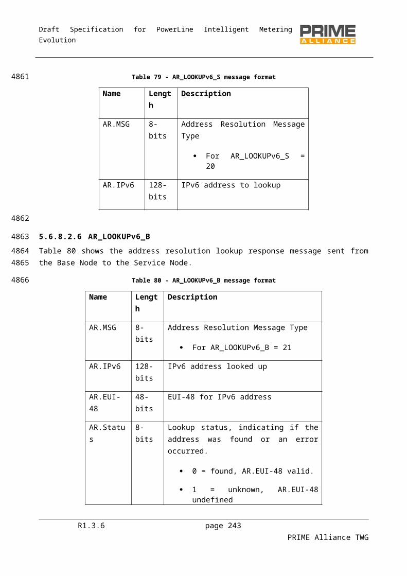
Draft Specification for PowerLine Intelligent Metering Evolution
Annex F (normative)
Profiles
Given the different applications which are foreseen for this specification compliant products, it is necessary to define different profiles. Profiles cover the functionalities that represent the respective feature set. They need to be implemented as written in order to assure interoperability.
This specification has a number of options, which, if exercised in different ways by different vendors, will hamper both compliance testing activities and future product interoperability. The profiles further restrict those options so as to promote interoperability and testability.
A specific profile will dictate which capabilities a Node negotiates through the Registering and Promotion processes.
F.1 Smart Metering Profile
The following options will be either mandatory or optional for Smart Metering Nodes.
REG.CAP_SW:
Base Node: Set to 1. Service Node: Set to 1.
REG.CAP_PA:
Base Node: optional. Service Node: optional.
REG.CAP_CFP:
Base Node: optional. Service Node: optional.
REG.CAP_DC
Base Node: optional. Service Node: optional.
REG.CAP_MC
Base Node: Set to 1. Service Node: optional.
REG.CAP_PRM
Base Node: Set to 1. Service Node: Set to 1.
REG.CAP_ARQ
R1.3.6 page 243 PRIME Alliance TWG
470147024703
470447054706
470747084709
47104711
4712
4713
4714
47154716
4717
47184719
4720
47214722
4723
47244725
4726
47274728
4729
47304731
4732
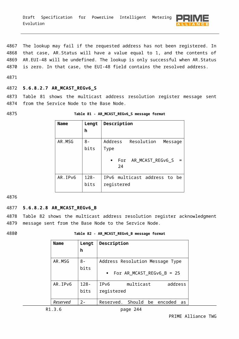
Draft Specification for PowerLine Intelligent Metering Evolution
Base Node: optional. Service Node: optional.
PRO.SWC_DC
Service Node: optional.
PRO.SWC_MC
Service Node: optional.
PRO.SWC_PRM
Service Node: Set to 1.
PRO.SWC_ARQ
Service Node: optional.
R1.3.6 page 244 PRIME Alliance TWG
47334734
4735
4736
4737
4738
4739
4740
4741
4742
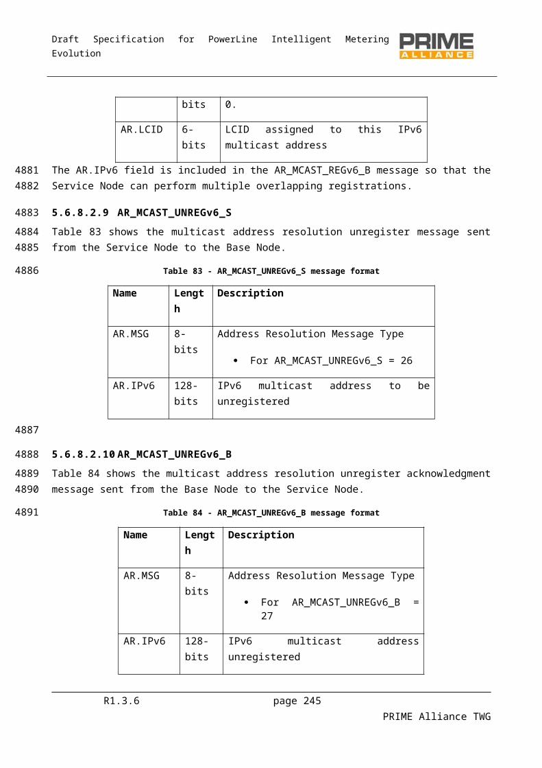
Draft Specification for PowerLine Intelligent Metering Evolution
Annex G (informative)
List of frequencies used
The table below gives the exact centre frequencies (in Hz) for the 97 subcarriers of the OFDM signal.
Table 135 – List of frequencies used
# Frequency # Frequency1 41992,18750
2 42480,46875 50 65917,96875
3 42968,75000 51 66406,25000
4 43457,03125 52 66894,53125
5 43945,31250 53 67382,81250
6 44433,59375 54 67871,09375
7 44921,87500 55 68359,37500
8 45410,15625 56 68847,65625
9 45898,43750 57 69335,93750
10 46386,71875 58 69824,21875
11 46875,00000 59 70312,50000
12 47363,28125 60 70800,78125
13 47851,56250 61 71289,06250
14 48339,84375 62 71777,34375
15 48828,12500 63 72265,62500
16 49316,40625 64 72753,90625
17 49804,68750 65 73242,18750
18 50292,96875 66 73730,46875
19 50781,25000 67 74218,75000
20 51269,53125 68 74707,03125
21 51757,81250 69 75195,31250
22 52246,09375 70 75683,59375
23 52734,37500 71 76171,87500
24 53222,65625 72 76660,15625
25 53710,93750 73 77148,43750
26 54199,21875 74 77636,71875
27 54687,50000 75 78125,00000
28 55175,78125 76 78613,28125
29 55664,06250 77 79101,56250
30 56152,34375 78 79589,84375
31 56640,62500 79 80078,12500
32 57128,90625 80 80566,40625
33 57617,18750 81 81054,68750
34 58105,46875 82 81542,96875
R1.3.6 page 245 PRIME Alliance TWG
474347444745
4746
4747
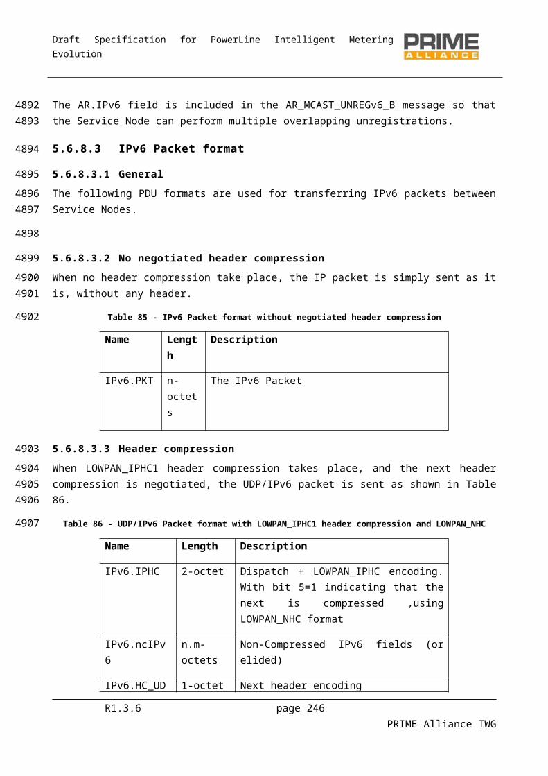
Draft Specification for PowerLine Intelligent Metering Evolution
# Frequency # Frequency35 58593,75000 83 82031,25000
36 59082,03125 84 82519,53125
37 59570,31250 85 83007,81250
38 60058,59375 86 83496,09375
39 60546,87500 87 83984,37500
40 61035,15625 88 84472,65625
41 61523,43750 89 84960,93750
42 62011,71875 90 85449,21875
43 62500,00000 91 85937,50000
44 62988,28125 92 86425,78125
45 63476,56250 93 86914,06250
46 63964,84375 94 87402,34375
47 64453,12500 95 87890,62500
48 64941,40625 96 88378,90625
49 65429,68750 97 88867,18750
Subcarrier #‘1’ is the pilot subcarrier. The rest are data subcarriers.
R1.3.6 page 246 PRIME Alliance TWG
4748
4749

Draft Specification for PowerLine Intelligent Metering Evolution
Annex H (informative)Informative
H.1 Data exchange between to IP communication peers
This example shows the primitive exchange between a service node (192.168.0.100/24) and a base node when the former wants to exchange IP packets with a third service node (192.168.0.101/24) whose IP address is in the same IP Subnetwork.
This example makes the following assumptions:
Service node (192.168.0.100) IPv4 SSCS does not exist so it needs to start a IPv4 SSCS and register its IP address in the base node prior to the exchange of IP packets.
Service node (192.168.0.101) has already registered its IP Address in the base node.
The steps illustrated in next page are:
1. The IPv4 layer of the service node (192.168.0.100) invokes the CL_IPv4_ESTABLISH.request primitive. To establish IPv4 SSCS, it is required,
a. To establish a connection with the base node so all address resolution messages can be exchanged over it.
b. To inform the service node MAC layer that IPv4 SSCS is ready to receive all IPv4 broadcasts packets. Note the difference between broadcast and multicast. To join a multicast group, the service node will need to inform the base node of the group it wants to join. This is illustrated in section A.2
2. The IPv4_ layer, once the IPv4 SSCS is established, needs to register its IP address in the base node. To do so, it will use the already established connection.
3. Whenever the IPv4_ needs to deliver an IPv4 packet to a new destination IP address, the following two steps are to be done (in this example, the destination IP address is 192.168.0.101).
a. As the IPv4 destination address is new, the IPv4 SSCS needs to request the EUI-48 associated to that IPv4 address. To do so, a lookup request message is sent to the base node.
b. Upon the reception of the EUI-48, a new connection (type = TYPE_CL_IPv4_UNICAST) is established so that all IP packets to be exchanged between 192.168.0.100 and 192.168.0.101 will use that connection.
R1.3.6 page 247 PRIME Alliance TWG
475047514752
4753
475447554756
4757
475847594760
4761
47624763
47644765
476647674768
47694770
47714772
47734774
477547764777
4778
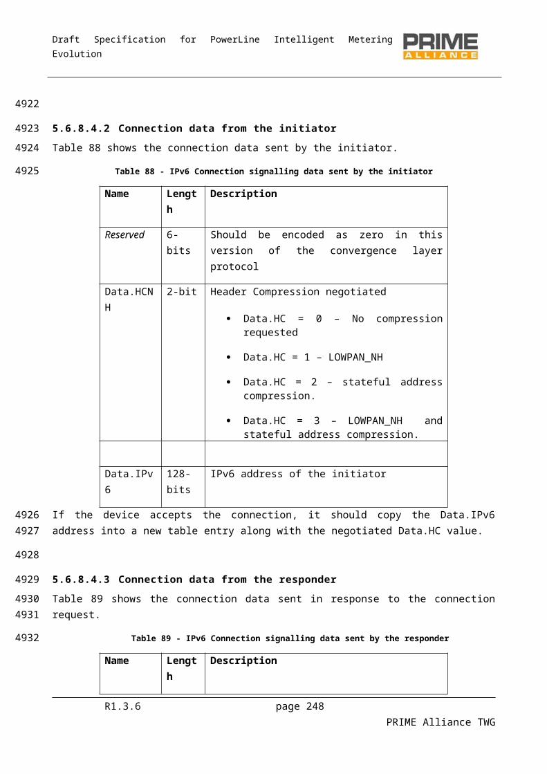
Draft Specification for PowerLine Intelligent Metering Evolution
Base NodeAPP – IPv4
Service NodeAPP – IPv4
Service NodeIPv4 SSCS
Service NodeMAC Layer
Base NodeMAC Layer
Base NodeIPv4 SSCS
CL_IPv4_ESTABLISHrequest
MAC_ESTABLISHrequest
( 00:00:00:00:00:00,TYPE_CL_IPv4_AR)
MAC_JOINrequest
( 00:00:00:00:00:00,LCI_CL_IPv4_BROADCAST)
MAC_JOINConfirm
(ConHandle = 101) CL_IPv4_ESTABLISHconfirm
MAC_ESTABLISHindication
( 00:00:00:00:00:00,TYPE_CL_IPv4_AR)
MAC_ESTABLISHresponse
MAC_ESTABLISHConfirm
(ConHandle = 100)
CL_IPv4_REGISTERrequest
192.168.0.100/24,192.168.0.1 (dgw)
MAC_DATArequest
(ConHandle = 100, AR_REGISTER_S)MAC_DATA
indication(ConHandle = 100, AR_REGISTER_S) MAC_DATA
confirm(AR_REGISTER_S)
MAC_DATArequest
(ConHandle = 100, AR_REGISTER_B)
MAC_DATAconfirm
(ConHandle = 100, AR_REGISTER_B)
MAC_DATAindication
(ConHandle = 100, AR_REGISTER_B) CL_IPv4_REGISTER
confirm192.168.0.100/24
CL_IPv4_DATArequest
Packet to 192.168.0.101/24
MAC_DATArequest
(ConHandle = 100, AR_LOOKUP_S)MAC_DATA
indication(ConHandle = 100, AR_LOOKUP_S) MAC_DATA
confirm(AR_LOOKUP_S)
MAC_DATArequest
(ConHandle = 100, AR_REGISTER_S)MAC_DATA
indication(ConHandle = 100, AR_REGISTER_S) MAC_DATA
confirm(AR_REGISTER_S)
MAC_DATArequest
(ConHandle = 100, AR_LOOKUP_B, eui-48)
MAC_DATAconfirm
(ConHandle = 100, AR_LOOKUP_B, eui_48 )
MAC_DATAindication
(ConHandle = 100, AR_LOOKUP_B, eui-48)
MAC_ESTABLISHindication
( eui-48,TYPE_CL_IPv4_UNICAST)
MAC_ESTABLISHresponse
MAC_ESTABLISHConfirm
(ConHandle = 120)
MAC_ESTABLISHrequest( eui-48,
TYPE_CL_IPv4_UNICAST)
Service NodeAPP – IPv4
Service NodeMAC Layer
Service NodeIPv4 SSCS
MAC_DATArequest
(ConHandle = 120, IP Packet)MAC_DATA
indication(ConHandle = 120,
IP Packet) MAC_DATAconfirm
(IP Packet) CL_IPv4_DATAconfirm
Packet to 192.168.0.101/24
CL_IPv4_DATAindicate
Packet from 192.168.0.100/24
DESTINATION SERVICE NODE: 192.168.0.101, eui-48
Figure H 1 - MSC of IPv4 SSCS services
R1.3.6 page 248 PRIME Alliance TWG
4779
4780
4781
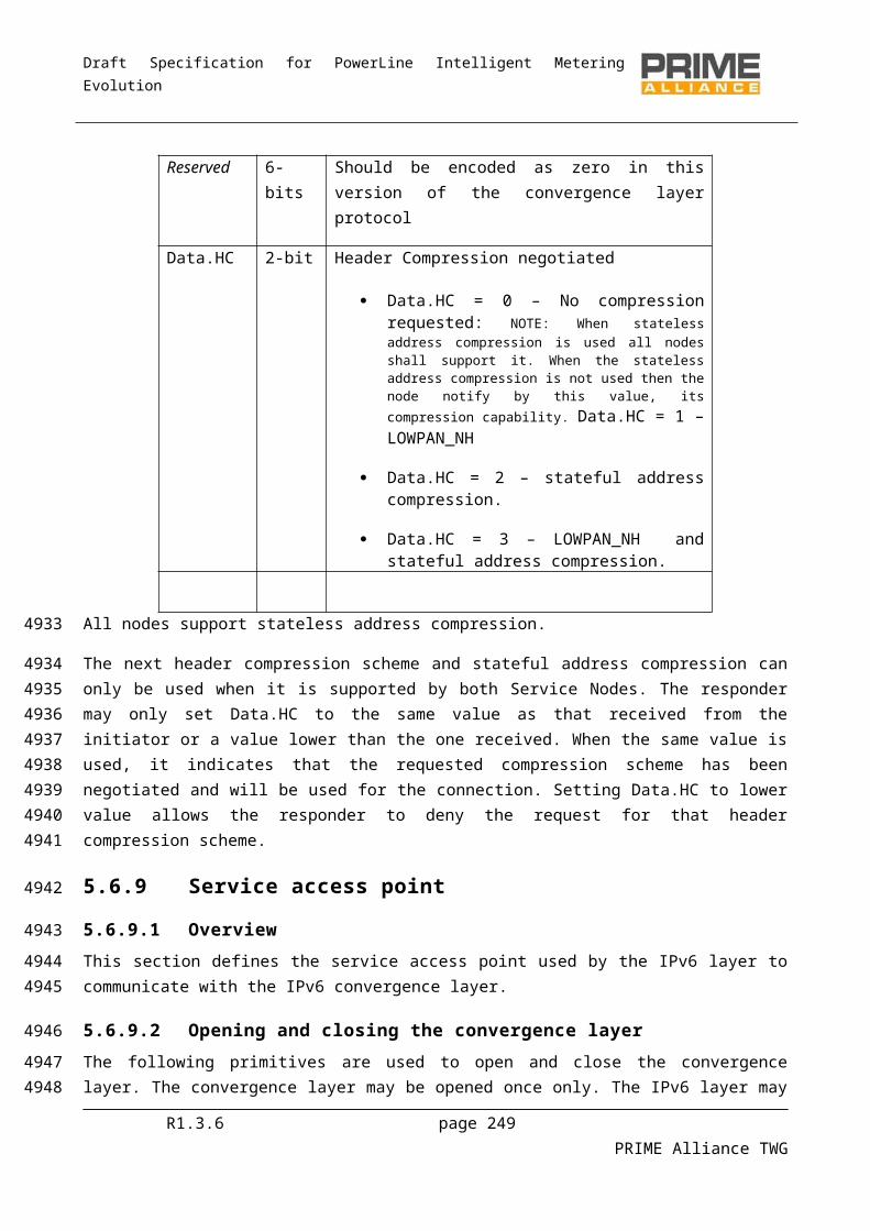
Draft Specification for PowerLine Intelligent Metering Evolution
H.2 Joining a multicast group
The figure below illustrates how a service node joins a multicast group. As mentioned before, main difference between multicast and broadcast is related to the messages exchanged. For broadcast, the MAC layer will immediately issue a MAC_JOIN.confirm primitive since it does not need to perform any end-to-end operation. For multicast, the MAC_JOIN.confirm is only sent once the signalling between the service node and base node is complete
Base NodeAPP – IPv4
Service NodeAPP – IPv4
Service NodeIPv4 SSCS
Service NodeMAC Layer
Base NodeMAC Layer
Base NodeIPv4 SSCS
CL_IPv4_IGMP_JOINRequest
224.0.0.1
MAC_JOINrequest
(Multicast=0, TYPE_CL_IPv4_UNICAST,
“JOIN to 224.0.0.1” )
CL_IPv4_IGMP_JOINConfirm
224.0.0.1
MAC_JOINindication
MAC_JOINResponse MAC_JOIN
Confirm
Multicast Group Join
MUL_JOIN_S
MUL_JOIN_B
Figure H 2-Joining MS
R1.3.6 page 249 PRIME Alliance TWG
4782
47834784478547864787
4788
4789
4790
4791
Draft Specification for PowerLine Intelligent Metering Evolution
The MSC below shows the 432 connection establishment and release. 432 SSCS is connection oriented. Before any 432_Data service can take place a connection establishment has to take place. The service node upper layer request a connexction establishment to thez 432 SSCS by providing to it the device identifier as parameter for the CL_432_Establish.request. With the help od the MAC layer services, the service node 432 SSCS request a connection establishment to the base node. This last one when the connection establishment is successful, notifies to the upper layers that a service node has joined the network with the help of the CL_432_Join.indication primitive and provides to the concerned service node a SSCS destination address in addition to its own SSCS address with the help of the MAC_Establish.response which crries out these parameters.
The CL_432_release service ends the connection. It is requested by the service node upper layer to the 432 SSCS which perform it with the help of MAC layer primitives. At the base node side the 432 SSCS notifies the end of the connection to the upper layer by a CL_432_Leave.indication.
Base Node AP
Base Node 432 SSCS
Base Node MAC
Service Node MAC
Service Node 432 SSCS
Service Node AP
CL_432_Establish.reqMAC_
Establish.reqMAC_Establish.indCL_432_
Join.ind MAC_Establish.rsp MAC_
Establish.cnf
CL_432_Release.reqMAC_
Release.reqMAC_Release.indCL_432_
Leave.ind MAC_Release.rsp MAC_
Release.cnf
CL_432_Establish.cnf
CL_432_Release.cnf
Figure H 3 - MSC 432 SSCS services
R1.3.6 page 250 PRIME Alliance TWG
479247934794479547964797479847994800
480148024803
4804
4805
4806
Draft Specification for PowerLine Intelligent Metering Evolution
Annex I (informative)
ARQ algorithm
The algorithm described here is just a recommendation with good performance and aims to better describe how ARQ works. However manufacturers could use a different algorithm as long as it complies with the specification.
When a packet is received the packet ID should be checked. If it is the expected ID and contains data, it shall be processed normally.. If the packet does not contain data, it can be discarded. If the ID does not match with the one expected, it is from the future and fits in the input window, then for all the packets not received with ID from the last one received to this one, we can assume that they are lost. If the packet contains data, save that data to pass it to the CL once all the packets before have been received and processed by CL.
If the packet ID does not fit in the input window, we can assume that it is a retransmission that has been delayed, and may be ignored.
If there is any NACK all the packets with PKTID lower than the first NACK in the list have been correctly received, and they can be removed from the transmitting window. If there is not any NACK and there is an ACK, the packets before the received ACK have been received and can be removed from the transmission window. All the packets in the NACK list should be retransmitted as soon as possible.
These are some situations for the transmitter to set the flush bit that may improve the average performance:
When the window of either the transmitter or the receiver is filled; When explicitly requested by the CL; After a period of time as a timeout.
The receiver has no responsibility over the ACK send process other than sending them when the transmitter sets the flush bit. Although it has some control over the flow control by the window field. On the other hand the receiver is able to send an ACK if it improves the ARQ performance in a given scenario. One example of this, applicable in most cases, could be making the receiver send an ACK if a period of time has been passed since the last sent ACK, to improve the bandwidth usage (and omit the timeout flush in the transmitter). In those situations the transmitter still has the responsibility to interoperate with the simplest receiver (that does not send it by itself).
It is recommended that the ARQ packet sender maintains a timer for every unacknowledged packet. If the packet cannot get successfully acknowledged when the timer expires, the packet will be retransmitted. This kind of timeout retry works independently with the NACK-initiated retries. After a pre-defined maximum number of timeout retries, it is strongly recommended to tear down the connection. This timeout and connection-teardown mechanism is to prevent the Node retry the ARQ packet forever. The exact number of the timeout values and the timeout retries are left for vendor’s own choice.
R1.3.6 page 251 PRIME Alliance TWG
480748084809
481048114812
481348144815481648174818
48194820
4821482248234824
48254826
482748284829
4830483148324833483448354836
483748384839484048414842

Draft Specification for PowerLine Intelligent Metering Evolution
List of authors
Ankou, Auguste (Itron)
Arribas, Miguel (Advanced Digital Design)
Arzuaga, Aitor (ZIV)
Arzuaga, Txetxu (ZIV)
Berganza, Inigo (Iberdrola)
Bertoni, Guido (STMicroelectronics)
Bisaglia, Paola (ST Microelectronics)
Cassin-Delauriere, Agnes (Texas Instruments)
Estopinan, Pedro (Advanced Digital Design)
Garai, Mikel (ZIV)
Du, Shu (Texas Instruments)
Garotta, Stefano (ST Microelectronics)
Lasciandare, Alessandro (ST Microelectronics)
Bois, Simone (ST Microelectronics)
Liu, Weilin (CURRENT Technologies International)
Llano, Asier (ZIV)
Lunn, Andrew (CURRENT Technologies International)
Miguel, Santiago(Advanced Digital Design)
Pulkkinen, Anssi (CURRENT Technologies International)
Rodriguez Roncero, Javier (Landis+Gyr)
Romero, Gloria (Itron)
Sánchez, Agustín (Landis+Gyr)
Sanz, Alfredo (Advanced Digital Design )
Schaub, Thomas (Landis+Gyr)
Sedjai, Mohamed (CURRENT Technologies International)
Sendin, Alberto (Iberdrola)
Sharma, Manu (CURRENT Technologies International)
Tarruell, Frederic(Itron)
Teijeiro Jesús(Advanced Digital Design)
Varadarajan, Badri (Texas Instruments)
Widmer, Hanspeter (CURRENT Technologies International)
Wikiera, Jacek (CURRENT Technologies International)
R1.3.6 page 252 PRIME Alliance TWG
4843
4844
4845
4846
4847
4848
4849
4850
4851
4852
4853
4854
4855
4856
4857
4858
4859
4860
4861
4862
4863
4864
4865
4866
4867
4868
4869
4870
4871
4872
4873
4874
4875
4876