Embed Size (px)
Citation preview
Primary reference in terms of air kerma for ionizing
radiation fields produced by an electrostatic electron
accelerator
Jean-Marc Bordy1*, Valentin Blideanu1, Arnaud Chapon2, Gabriel Dupont2, Dorin
Dusciac1, Jean Gouriou1, Frederic Laine3, and Maiwenn Le Roy1
1CEA, LIST, Laboratoire National Henri Becquerel (LNE-LNHB), CEA-Saclay, 91191 Gif sur
Yvette Cedex, France 2ATRON METROLOGY, 14 allée des vindits, parc d'activité des fourches, 50130 Cherbourg en
Cotentin, France 3CEA, LIST, DM2I SCI LCAE, CEA-Saclay, 91191 Gif sur Yvette Cedex, France
Abstract. Based on a radiation field produced by an electrostatic
accelerator, a radiation survey meter test and calibration facility has been
designed and characterized in terms of air kerma and ambient dose
equivalent. The electron beam impinges a tantalum target to produce X-rays.
The spectrum has been measured and calculated. Traceability to the
International System of units is achieved by means of a calibration with a
primary dosimeter for air kerma.
1 INTRODUCTION
The French legislation has introduced a maximum period of use for ionization radiation
isotopic sources; beyond 10 years these must be changed or can be requalified for a limited
period. To reduce the operating costs of reference and calibration facilities and to facilitate
calibration procedures, the idea came to produce bremsstrahlung photon radiation fields from
linear electron accelerators. A first realization was made at CEA/LNE-LNHB, based on a
medical LINAC Saturne 43, leading to the characterization in terms of air kerma and dose
equivalent of a radiation field with an average X-ray energy of about 7 MeV for an initial
electron beam of 18 MeV [1].
CEA/LNE-LNHB characterized a facility designed by the private company ATRON
METROLOGY for the test and calibration of radiation survey meters in terms of air kerma
and ambient dose equivalent. This facility, based on the same principle, targets an energy
domain between 137Cs and 60Co. This publication describes the technological choices of
ATRON METROLOGY and the entire process of (i) the primary characterization of ATRON
METROLOGY beams in terms of air kerma and (ii) the establishment of conversion
coefficients from this quantity to the ambient dose equivalent by CEA/LNE-LNHB.
2 ATRON METROLOGY FACILITY
ATRON METROLOGY chose an electrostatic Singletron accelerator from HVE (High
Voltage Engineering Europa B.V., Amersfoort, Netherlands). It delivers a continous beam of
electrons, the maximum high voltage is 3.5 MV. The 22 x 4 cm² target is made of a tantalum
plate (73Ta), 1.5 mm thick. The electron beam scans this plate. The current range lie from a
© The Authors, published by EDP Sciences. This is an open access article distributed under the terms of the Creative Commons Attribution License 4.0 (http://creativecommons.org/licenses/by/4.0/).
19th International Congress of Metrology, 15003 (2019) https://doi.org/10.1051/metrology/201915003
few 0.1 pA to 1 mA [2]. Within a range between 200 kV and 3.5 MV, the accelerator has
three pre-settings in energy 1.25 MeV, 2 MeV or 3 MeV.
ATRON METROLOGY developed, in collaboration with the Laboratoire de Physique
Corpusculaire de Caen (LPC Caen – ENSICAEN/UNICAEN/CNRS): (i) a transmission
ionization chamber to regulate the electron beam at low dose rates, (ii) a sample conveyor
positioned at a distance of 1 or 3 meters from the target. Two cavity chambers PTW TM32002
(1 L) associated with PTW UNIDOS Webline T10021 electrometers are fixed on the latter
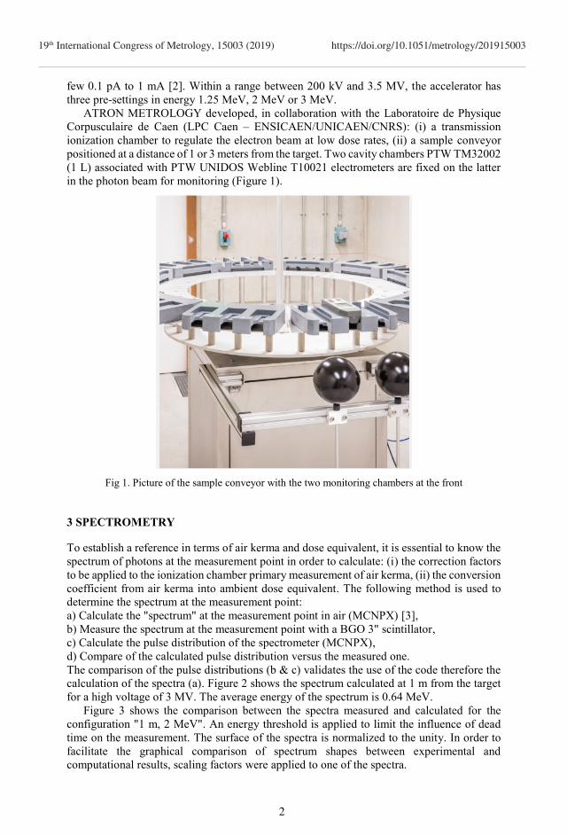
in the photon beam for monitoring (Figure 1).
Fig 1. Picture of the sample conveyor with the two monitoring chambers at the front
3 SPECTROMETRY
To establish a reference in terms of air kerma and dose equivalent, it is essential to know the
spectrum of photons at the measurement point in order to calculate: (i) the correction factors
to be applied to the ionization chamber primary measurement of air kerma, (ii) the conversion
coefficient from air kerma into ambient dose equivalent. The following method is used to
determine the spectrum at the measurement point:
a) Calculate the "spectrum" at the measurement point in air (MCNPX) [3],
b) Measure the spectrum at the measurement point with a BGO 3" scintillator,
c) Calculate the pulse distribution of the spectrometer (MCNPX),
d) Compare of the calculated pulse distribution versus the measured one.
The comparison of the pulse distributions (b & c) validates the use of the code therefore the
calculation of the spectra (a). Figure 2 shows the spectrum calculated at 1 m from the target
for a high voltage of 3 MV. The average energy of the spectrum is 0.64 MeV.
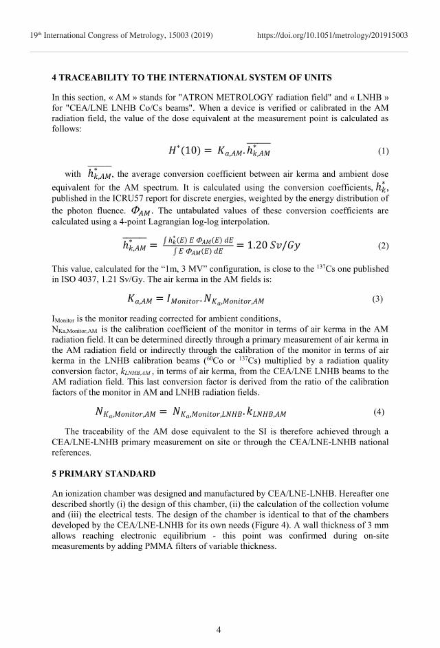
Figure 3 shows the comparison between the spectra measured and calculated for the
configuration "1 m, 2 MeV". An energy threshold is applied to limit the influence of dead
time on the measurement. The surface of the spectra is normalized to the unity. In order to
facilitate the graphical comparison of spectrum shapes between experimental and
computational results, scaling factors were applied to one of the spectra.
2
19th International Congress of Metrology, 15003 (2019) https://doi.org/10.1051/metrology/201915003
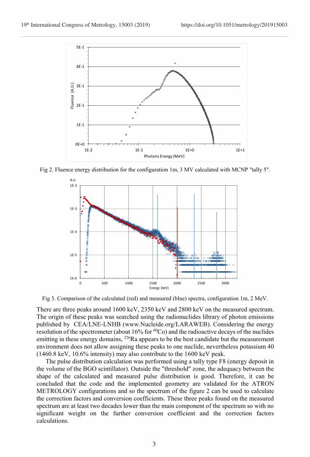
Fig 2. Fluence energy distribution for the configuration 1m, 3 MV calculated with MCNP "tally 5".
Fig 3. Comparison of the calculated (red) and measured (blue) spectra, configuration 1m, 2 MeV.
There are three peaks around 1600 keV, 2350 keV and 2800 keV on the measured spectrum.
The origin of these peaks was searched using the radionuclides library of photon emissions
published by CEA/LNE-LNHB (www.Nucleide.org/LARAWEB). Considering the energy
resolution of the spectrometer (about 16% for 60Co) and the radioactive decays of the nuclides
emitting in these energy domains, 226Ra appears to be the best candidate but the measurement
environment does not allow assigning these peaks to one nuclide, nevertheless potassium 40
(1460.8 keV, 10.6% intensity) may also contribute to the 1600 keV peak.
The pulse distribution calculation was performed using a tally type F8 (energy deposit in
the volume of the BGO scintillator). Outside the "threshold" zone, the adequacy between the
shape of the calculated and measured pulse distribution is good. Therefore, it can be
concluded that the code and the implemented geometry are validated for the ATRON
METROLOGY configurations and so the spectrum of the figure 2 can be used to calculate
the correction factors and conversion coefficients. These three peaks found on the measured
spectrum are at least two decades lower than the main component of the spectrum so with no
significant weight on the further conversion coefficient and the correction factors
calculations.
0E+0
1E-1
2E-1
3E-1
4E-1
5E-1
1E-2 1E-1 1E+0 1E+1
Flu
ence
(A
.U.)
Photons Energy (MeV)
1E-6
1E-5
1E-4
1E-3
1E-2
0 500 1000 1500 2000 2500 3000Energy (keV)
A.U.
3
19th International Congress of Metrology, 15003 (2019) https://doi.org/10.1051/metrology/201915003
4 TRACEABILITY TO THE INTERNATIONAL SYSTEM OF UNITS
In this section, « AM » stands for "ATRON METROLOGY radiation field" and « LNHB »
for "CEA/LNE LNHB Co/Cs beams". When a device is verified or calibrated in the AM
radiation field, the value of the dose equivalent at the measurement point is calculated as
follows:
𝐻∗(10) = 𝐾𝑎,𝐴𝑀. ℎ𝑘,𝐴𝑀∗
(1)
with ℎ𝑘,𝐴𝑀∗
, the average conversion coefficient between air kerma and ambient dose
equivalent for the AM spectrum. It is calculated using the conversion coefficients, ℎ𝑘∗,
published in the ICRU57 report for discrete energies, weighted by the energy distribution of
the photon fluence. 𝐴𝑀. The untabulated values of these conversion coefficients are
calculated using a 4-point Lagrangian log-log interpolation.
ℎ𝑘,𝐴𝑀∗ = ∫ ℎ𝑘
∗ (𝐸) 𝐸 𝐴𝑀(𝐸) 𝑑𝐸
∫ 𝐸 𝐴𝑀(𝐸) 𝑑𝐸= 1.20 𝑆𝑣/𝐺𝑦 (2)
This value, calculated for the “1m, 3 MV” configuration, is close to the 137Cs one published
in ISO 4037, 1.21 Sv/Gy. The air kerma in the AM fields is:
𝐾𝑎,𝐴𝑀 = 𝐼𝑀𝑜𝑛𝑖𝑡𝑜𝑟. 𝑁𝐾𝑎,𝑀𝑜𝑛𝑖𝑡𝑜𝑟,𝐴𝑀 (3)
IMonitor is the monitor reading corrected for ambient conditions, NKa,Monitor,AM is the calibration coefficient of the monitor in terms of air kerma in the AM
radiation field. It can be determined directly through a primary measurement of air kerma in
the AM radiation field or indirectly through the calibration of the monitor in terms of air
kerma in the LNHB calibration beams (60Co or 137Cs) multiplied by a radiation quality
conversion factor, kLNHB,AM , in terms of air kerma, from the CEA/LNE LNHB beams to the
AM radiation field. This last conversion factor is derived from the ratio of the calibration
factors of the monitor in AM and LNHB radiation fields.
𝑁𝐾𝑎,𝑀𝑜𝑛𝑖𝑡𝑜𝑟,𝐴𝑀 = 𝑁𝐾𝑎,𝑀𝑜𝑛𝑖𝑡𝑜𝑟,𝐿𝑁𝐻𝐵. 𝑘𝐿𝑁𝐻𝐵,𝐴𝑀 (4)
The traceability of the AM dose equivalent to the SI is therefore achieved through a
CEA/LNE-LNHB primary measurement on site or through the CEA/LNE-LNHB national
references.
5 PRIMARY STANDARD
An ionization chamber was designed and manufactured by CEA/LNE-LNHB. Hereafter one
described shortly (i) the design of this chamber, (ii) the calculation of the collection volume
and (iii) the electrical tests. The design of the chamber is identical to that of the chambers
developed by the CEA/LNE-LNHB for its own needs (Figure 4). A wall thickness of 3 mm
allows reaching electronic equilibrium - this point was confirmed during on-site
measurements by adding PMMA filters of variable thickness.
4
19th International Congress of Metrology, 15003 (2019) https://doi.org/10.1051/metrology/201915003
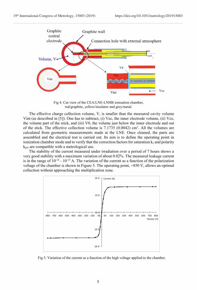
Fig 4. Cut view of the CEA/LNE-LNHB ionisation chamber,
red/graphite, yellow/insulator and grey/metal.
The effective charge collection volume, V, is smaller than the measured cavity volume
Vint (as described in [5]). One has to subtract, (i) Vec, the inner electrode volume, (ii) Vce,
the volume part of the stick, and (iii) V0, the volume just below the inner electrode and out
of the stick. The effective collection volume is 7.1735 (0.0042) cm3. All the volumes are
calculated from geometric measurements made at the LNE. Once cleaned, the parts are
assembled and the electrical test is carried out. Its aim is to define the operating point in
ionization chamber mode and to verify that the correction factors for saturation ks and polarity
kpol are compatible with a metrological use.
The stability of the current measured under irradiation over a period of 7 hours shows a
very good stability with a maximum variation of about 0.02%. The measured leakage current
is in the range of 10-16 - 10-15 A. The variation of the current as a function of the polarization
voltage of the chamber is shown in Figure 5. The operating point, +850 V, allows an optimal
collection without approaching the multiplication zone.
Fig 5. Variation of the current as a function of the high voltage applied to the chamber.
-2E-9
-1E-9
0E+0
1E-9
2E-9
-850 -750 -650 -550 -450 -350 -250 -150 -50 50 150 250 350 450 550 650 750 850
Tension (V)
Current (A)
0E+0
5
19th International Congress of Metrology, 15003 (2019) https://doi.org/10.1051/metrology/201915003
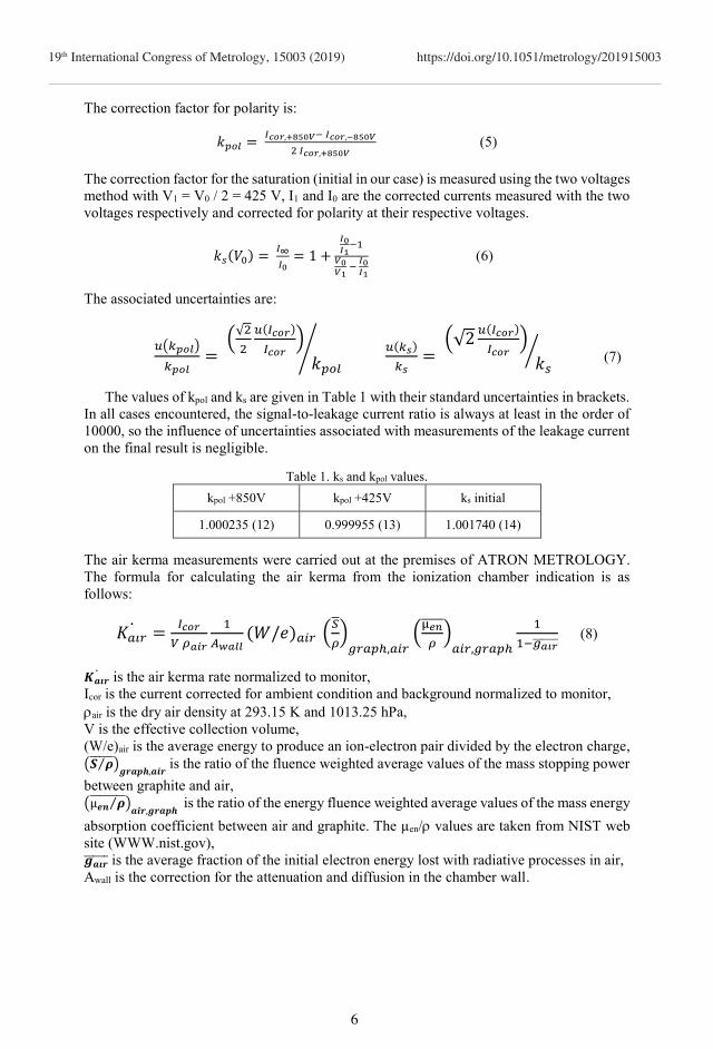
The correction factor for polarity is:
𝑘𝑝𝑜𝑙 = 𝐼𝑐𝑜𝑟,+850𝑉− 𝐼𝑐𝑜𝑟,−850𝑉
2 𝐼𝑐𝑜𝑟,+850𝑉 (5)
The correction factor for the saturation (initial in our case) is measured using the two voltages
method with V1 = V0 / 2 = 425 V, I1 and I0 are the corrected currents measured with the two
voltages respectively and corrected for polarity at their respective voltages.
𝑘𝑠(𝑉0) = 𝐼∞
𝐼0= 1 +
𝐼0𝐼1
−1
𝑉0𝑉1
− 𝐼0𝐼1
(6)
The associated uncertainties are:
𝑢(𝑘𝑝𝑜𝑙)
𝑘𝑝𝑜𝑙=
(√2
2
𝑢(𝐼𝑐𝑜𝑟)
𝐼𝑐𝑜𝑟)
𝑘𝑝𝑜𝑙
⁄ 𝑢(𝑘𝑠)
𝑘𝑠=
(√2𝑢(𝐼𝑐𝑜𝑟)
𝐼𝑐𝑜𝑟)
𝑘𝑠
⁄ (7)
The values of kpol and ks are given in Table 1 with their standard uncertainties in brackets.
In all cases encountered, the signal-to-leakage current ratio is always at least in the order of
10000, so the influence of uncertainties associated with measurements of the leakage current
on the final result is negligible.
Table 1. ks and kpol values.
kpol +850V kpol +425V ks initial
1.000235 (12) 0.999955 (13) 1.001740 (14)
The air kerma measurements were carried out at the premises of ATRON METROLOGY.
The formula for calculating the air kerma from the ionization chamber indication is as
follows:
𝐾𝑎𝑖𝑟 =
𝐼𝑐𝑜𝑟
𝑉 𝜌𝑎𝑖𝑟
1
𝐴𝑤𝑎𝑙𝑙(𝑊/𝑒)𝑎𝑖𝑟 (
𝑆
𝜌
)
𝑔𝑟𝑎𝑝ℎ,𝑎𝑖𝑟(
µ𝑒𝑛
𝜌
)𝑎𝑖𝑟,𝑔𝑟𝑎𝑝ℎ
1
1−𝑔𝑎𝑖𝑟 (8)
𝑲𝒂𝒊𝒓 is the air kerma rate normalized to monitor,
Icor is the current corrected for ambient condition and background normalized to monitor,
air is the dry air density at 293.15 K and 1013.25 hPa,
V is the effective collection volume,
(W/e)air is the average energy to produce an ion-electron pair divided by the electron charge,
(𝑺 𝝆⁄ )𝒈𝒓𝒂𝒑𝒉,𝒂𝒊𝒓
is the ratio of the fluence weighted average values of the mass stopping power
between graphite and air,
(µ𝒆𝒏 𝝆⁄ )𝒂𝒊𝒓,𝒈𝒓𝒂𝒑𝒉
is the ratio of the energy fluence weighted average values of the mass energy
absorption coefficient between air and graphite. The µen/ values are taken from NIST web
site (WWW.nist.gov),
𝒈𝒂𝒊𝒓 is the average fraction of the initial electron energy lost with radiative processes in air,
Awall is the correction for the attenuation and diffusion in the chamber wall.
6
19th International Congress of Metrology, 15003 (2019) https://doi.org/10.1051/metrology/201915003
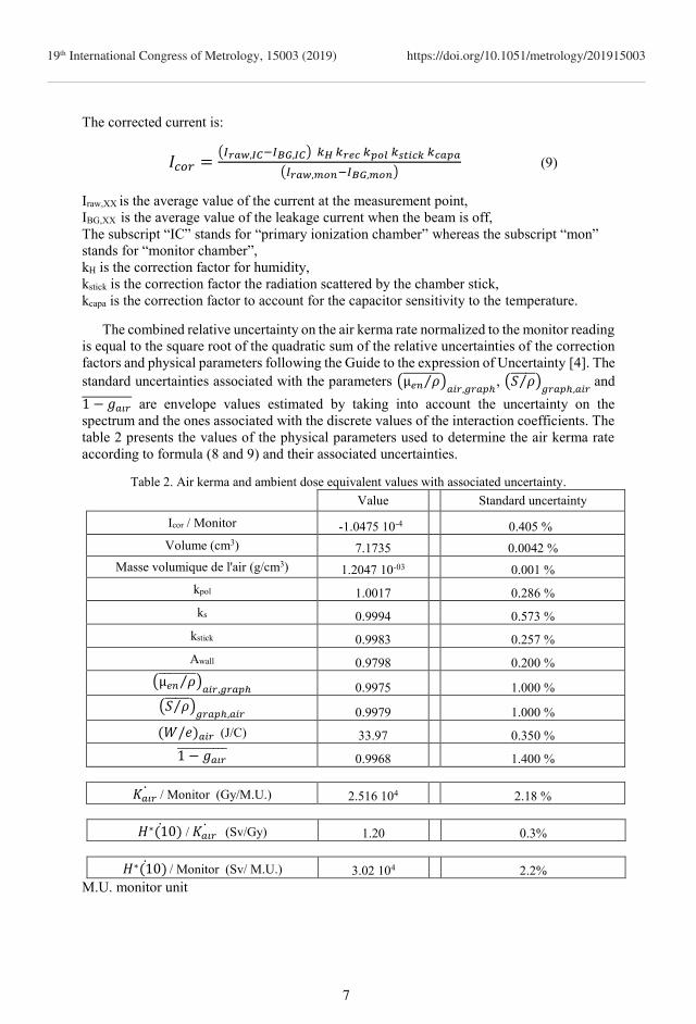
The corrected current is:
𝐼𝑐𝑜𝑟 =(𝐼𝑟𝑎𝑤,𝐼𝐶−𝐼𝐵𝐺,𝐼𝐶) 𝑘𝐻 𝑘𝑟𝑒𝑐 𝑘𝑝𝑜𝑙 𝑘𝑠𝑡𝑖𝑐𝑘 𝑘𝑐𝑎𝑝𝑎
(𝐼𝑟𝑎𝑤,𝑚𝑜𝑛−𝐼𝐵𝐺,𝑚𝑜𝑛) (9)
Iraw,XX is the average value of the current at the measurement point,
IBG,XX is the average value of the leakage current when the beam is off,
The subscript “IC” stands for “primary ionization chamber” whereas the subscript “mon”
stands for “monitor chamber”,
kH is the correction factor for humidity,
kstick is the correction factor the radiation scattered by the chamber stick,
kcapa is the correction factor to account for the capacitor sensitivity to the temperature.
The combined relative uncertainty on the air kerma rate normalized to the monitor reading
is equal to the square root of the quadratic sum of the relative uncertainties of the correction
factors and physical parameters following the Guide to the expression of Uncertainty [4]. The
standard uncertainties associated with the parameters (µ𝑒𝑛 𝜌⁄ )𝑎𝑖𝑟,𝑔𝑟𝑎𝑝ℎ
, (𝑆 𝜌⁄ )𝑔𝑟𝑎𝑝ℎ,𝑎𝑖𝑟
and
1 − 𝑔𝑎𝑖𝑟 are envelope values estimated by taking into account the uncertainty on the
spectrum and the ones associated with the discrete values of the interaction coefficients. The
table 2 presents the values of the physical parameters used to determine the air kerma rate
according to formula (8 and 9) and their associated uncertainties.
Table 2. Air kerma and ambient dose equivalent values with associated uncertainty.
Value Standard uncertainty
Icor / Monitor -1.0475 10-4 0.405 %
Volume (cm3) 7.1735 0.0042 %
Masse volumique de l'air (g/cm3) 1.2047 10-03 0.001 %
kpol 1.0017 0.286 %
ks 0.9994 0.573 %
kstick 0.9983 0.257 %
Awall 0.9798 0.200 %
(µ𝑒𝑛 𝜌⁄ )𝑎𝑖𝑟,𝑔𝑟𝑎𝑝ℎ
0.9975 1.000 %
(𝑆 𝜌⁄ )𝑔𝑟𝑎𝑝ℎ,𝑎𝑖𝑟
0.9979 1.000 %
(𝑊/𝑒)𝑎𝑖𝑟 (J/C) 33.97 0.350 %
1 − 𝑔𝑎𝑖𝑟 0.9968 1.400 %
𝐾𝑎𝑖𝑟 / Monitor (Gy/M.U.) 2.516 104 2.18 %
𝐻∗(10) / 𝐾𝑎𝑖𝑟 (Sv/Gy) 1.20 0.3%
𝐻∗(10) / Monitor (Sv/ M.U.) 3.02 104 2.2%
M.U. monitor unit
7
19th International Congress of Metrology, 15003 (2019) https://doi.org/10.1051/metrology/201915003
6 CONCLUSIONS
An innovative way to meet the needs of nuclear industry in terms of radiation survey meter
verification and calibration services was developed through an efficient collaboration
between the French national metrology laboratory (CEA/LNE-LNHB) and industry
(ATRON METROLOGY). The facility allows changing the dose equivalent rate without
moving the dosimeters just by tuning the electron beam intensity over 8 decades and can
automatically calibrate up to 32 devices carried by a coveyor. The traceability to the
international system of units is achieved through a primary measurement of the air kerma on-
site and a regular calibration/verification in front of the French national references of
CEA/LNE-LNHB.
References
[1] D. Dusciac, J.-M. Bordy, J. Daures and V. Blideanu, EPJ Web of Conferences,
DOI: http://dx.doi.org/10.1051/epjconf/201612400004, 124 (2016),
[2] A. Chapon - G. Dupont - J.M. Bordy, Revue Générale Nucléaire, 6, 48-52 (2016).
[3] G. Pelowitz, MCNPX user's manual, version 2.5.0 (2005)
[4] ISO 13005, Guide pour l’expression des incertitudes de mesures, (1999).
[5] F Delaunay, M Donois, J Gouriou, E Leroy and A Ostrowsky, New LNHB primary
standard for 60Co air kerma Metrologia 47 (2010) 652, https://doi.org/10.1088/0026-
1394/47/6/004
8
19th International Congress of Metrology, 15003 (2019) https://doi.org/10.1051/metrology/201915003