Embed Size (px)
Citation preview

PRilSM WORKING PAPER
No. 86-001
SPREAD ALOHA FOR VSATS
NORMAN ABRAMSON

SPREAD ALOH~ FOR VSA~'s
by
'Roman Abrnsou Univers.lt;y of Hawaii.
Honolulu~ Han.U. 96822
Ahst:ract
Spre&d ALOHA. is a DIUl.ti ple access proto(l.01 using conv•ntional ALOHA packets spre•d in tiH~ so that the packet con.tent.ion. i nterval at th• output of the packet i:ec.aiver i• not increased . Packet:• cransmitted using a Spread ALOHA protocol ca11 overl a.p in ch• physical channel 'Iii.t h high pr obability. but still b,e separac•d at the output of • matched filter 1 .s.o that the probabi.licy of overlap ac the r•ce.iver output 1• low. .Spread .ALOHA operati.on of a data channel coabin.es several characteristic.a of ALOHA channels and. Spread Spect:rwl. channel,. The W1e of Spread ALOHA c.an achieve certain eff'ieiencies and .simpl icities of operation which are not possible in conventional ALOHA channel• or conventional S·preacl. Spectrum channel s. In particular. for the case of a l arge num_ber of small eart:h stations acces.sing a single sat ellite t-i:an:spander i.n a data network. no s i gnalling technique b po.saible which can. achi .ve a higher averag de.ta throughput for a si.ven average power and a giver. bandwidth than Spread ALOHA.
This report: is preU.aina.Ty only. It cont:atrua an ex.planati":n. of the baeic ele ent• of a Spread ALOHA channel together with 11011. n.ot.atio:nal mat erial which ae"es to euphasize che conn•otion between Spread ALOHA, couventio:nal Spread Spectrum and algebraic codin,g theory . A more detailed report wil l be provided a.t a la tar date .
This re.search was supported by the. Social Science Research I n;stit.uce. and by the ALOHA sYSTEM Iaduse.ri&l Affil iates Progr withi n the P,acific Research Ins ti tut.e for Infol:mati.on Sciences and Managemen~ (PRISM) • at the University of Hawaii .

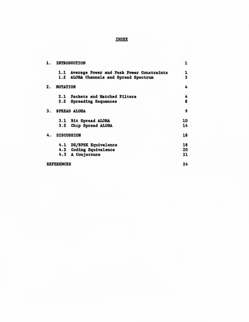
1. DmlODOCTIOl!I l
1.l Average Pover end Peak Power Conatl:einta 1 1.2 Al.OBA Channels end Spread Spectrum 3
2. NOTATIOJII 4
2 .1 Packets and Matched Filters 4 2.2 Spreading Sequences 8
3. SPB.IW) ALOHA 9
3.1 Bit Spread ALOHA 10 3.2 Chip Spread ALOHA 14
4. DISCOSSIOII 18
4. l l>S/BPSK Equivalence 18 4.2 Coding Equivalence 20 4.3 A Conjecture 21
IUEIENCES 24

1. INTJI.Ol>UCTIOl!I
1,l Average Povar and Peak i'over Conatrainta
The question of the throughput of an ALOHA channel is usually analyzed in
teX'llls of the ratio of the 111&XiDua data rate of the channel, when that rate
is limited by the multi•acceaa protocol of the channel, to the maximum data
rate of the channel when operated in a point-to-point mode (1). For the
cue of the original ALOHANET (2) as well as aany other siruations when the
average transmitter power is not an important system constraint such an
analyai• is appropriate. In other caaes however, such as a satellite
channel with an average power limitation, this conventional analysis can be
misleading. For example, in an ALOHA channel, or any burst channel, the
transmission of packets can result in a low duty cycle use of the channel
and a corresponding low duty cycle drain on the power from the satellite
transponder. Thia lowered demand for average power out of the satellite
transponder by an ALOHA channel can be translated immediately into higher
power availability for other channels (either ALOHA or point-to-point)
sharing the a&111a transponder by means of a conventional FDM arrangement [3 ).
Thia observation suggests a comparison of the data rate of an ALOHA channel
with that which can be achieved in a point•to•point channel under a given
average power constraint. (Conventional analysis may be thought of as a
comparison under a peak power constraint.)
It has been shown [l; section VJ that when the m"1(inlum data rate of an ALOHA
channel is compared to that of a conventional point-to-point channel of the
same average power, the ratio of data rates can easily exceed the l/2e (or
1/e for slotted ALOHA) value sometimes cited as the •capacity• of an ALOHA
channel. The data rates have been calculated (1; section VJ for slotted and
l

unalotted channels when used with both linear and hard-limiting
transponders . In all four cases it has been shown that when the average
(but not necessarily the pealc) signal-to-noise ratio is small and the
channel is operated under low duty cycle conditions then the average data
rate is given by the classical Shannon equation [4]:
'i log (l + P/5) (l)
where Wis the channel bandwidth, N is the average noise power in the
receiver and Pis average signal power in the receiver. Note that when D,
the average duty cycle, is small the average signal power during a burst
will be P/D.
The significance of this result to a network composed of very saiall aperture
terminals (VSAT's) should be emphasized. When a network is co111posed of many
small earth stations and the signal-to-noise ratio of the received s ignal is
low, equation (1) will apply when the stations use an ALOHA protocol with a
low value for the channel traffic, G. Under these conditions we can
conclude that no signalling method can operate at a higher data rate than an
ALOHA channel for a given average transmitter power and a given bandwidth.
Perhapa the most surprising aspect of this result is that it applies to
point-to-point as well as to multiple access channels. Thus the penalty of
l/2e or l/e for slotted ALOHA channels (without the use of contention
resolution algorithms (5,6)) is only required in the case of channels with a
peak power constraint. For channels with an average power ·constraint there
is no capacity penalty which must be paid for multiple access operation, and
the amount of data which can be transmitted among a thousand, or a million,
earth stations in a data network is th• same as can be transmitted in a
single link between only two of those stations .
2
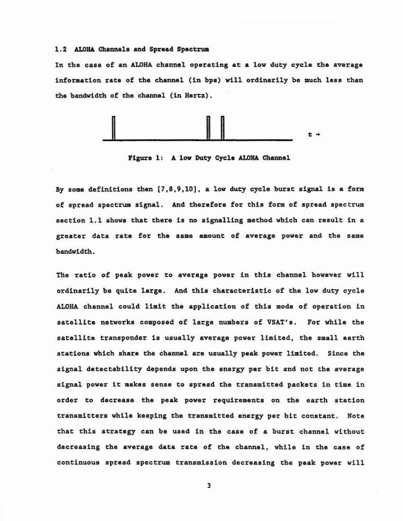
1.2 ALOHA Cb.anne1s and spr .. d Specttum
In. the. case of an ALOHA c:::hannel op ratln,g at a low 4ucy cycle the average
infornat.ion rate of the channel (:tn bpa) will ordinarily be !IWCh less t:h.a.n
th• bandwidth of t:be channel (in He:ttz).
I I I C.,..
Flgun l: A lov Duty Cycle ALOHA Channel
By •olll• definitions th•n (7, 8. 9 .10] • a . low duty cyole burst signal is • form
of spread spectrw. signal. A:ncl therefore for thi,11 fom o~ spread. spec trua
,ec:.tion: 141 sh.ow• that there b no aignalling method wbic.b can result t.n a.
greater data rate foi: th• same aaiount of average pow:er and the same
bandwi.dcb.
Tlie ratio of peak power to ,verage power in this channel hova'1er will
ordinarily be quit.e large 4 And this characteristic of the low duty cycle
ALOHA. channel cou.ld limit t:he application of eh:ls mode of operation in
sat:elU.te networks composed of large. numbers of VSA.Tt a. For whil• the
sat.elli Ce transponder is usually aveTage power lbai ted, the small earth
stations whi.ch .share the channel are. u.sually peak power limited. Since the
signal detectabilH:y depends upon. th• energy p•r bit and not th.a ave.rage
s .i .gnal powe.r it makes sense to spread Che transmitte.d packets in time. in
order Co deereue the pe.ak power requirements on t:h.e eatth station.
trans iceers while keeping the transmitted energy per bi1: ,constant. Note
that this scra.tegy can be used in the case. of ,a burst channel with.out
deel'easing the average data rate of the channe.l~ while. i .n the ,case of
continuous sp,read. spectrum. transmission decreasiug the -pe.ak powe.r will

decrease the channel data rate . In section 3, we show how it is possible to
spread the packets of a low duty cycle ALOHA channel in time, without:
increasing the probability of packet overlap out of the channel receiver .
But first we use section 2 co introduce a notation which will be helpful in
the remainder of thLv paper.
2. NOTATION
2.l Paclteca and Matched Pilters
Consider tha case of packet transmission where each packet consiscs of
exactly n bits . Lat the value of these bits be dJ' where the data sequence
d., 1a given by
j•O,l ... n•l (2)
In this report we shall be concerned with binary phase-shift keyed (BPSK)
channels for transmission of packets and with the representation of these
packets in a form which emphasizes their correspondence to conventional
direct sequence spread spectrwa channels (7J . Let p(t) be the bit pulse
waveform used in the channel so that a single packet, O(t), consisting of n
bit transmissions at the times 0,1, .. . n•l can be represented as
a•l
O(t) • L d.,p(t•j) (3) J-0
A useful device which allows us to separate the analog affects of pulse
shape from the digital effects of the data sequence is to represent D(t) as
the convolucion of the pulse p(t) with a sequence of ilnpulses multiplied by
the data sequence values dJ. Than
n·1 D(t) - L d,6(t• j) * p(t)
J-0
4
(4)
Note that D(t) can be chou.ghc of as th , outpuc of a tiae f.:nvariant. linear
opera~or with illpulse r .sponse. p(t:) ~ when the inpu.1: is
d(t)
n•1
dCt> .. I d.1&et·J > J-0
I p(t) I O(t)
J'.f.gura 2: The !a~ket: •• dle Output of a Lmea-r filter
(5)
Th.e r .ception of a sequanc.e of packets occurr1:na ae random cimes in a
multiple access ch.annel b usually broken do1m .into two st:ages ••• a packet:
detection an,d synchronization. .stage ( to detec.t the p:r•a•nce o.f the. ·packet:.
an4 to synchronize) and a si.gnal detection st:age (to dem.odulaee the signal
and to 4eten.itui1 the val.ues of the inf'oraati.on beari.ng ale nts, d.,). W'e
ass~e the packet D(t::) is tr.us itted in a channel with additive white
Gaus.s:l.an noise (ASIGN), n(t), so that the received signal a(t) is
a(t) - D(t) + a(t) (6)
UndeJ: a wide varieey of &SSUllptions. a key element of t::he packet receiver
(11. 12] i!l th.e satched filter • -·· mat:Gbed to the pulse shape, p(t) .
Ignorlng question,a of ti111.e delays in t:be r ceiver, we can represent the
ialpul.se respoue functi.oa of the matched filter as p( •t). and t:he output of
a(t:) • D(t) + n(t) I b(t) p( ~t) -~~~ I
Pigure 3% lapuc and Output of the Match cl Filter
5
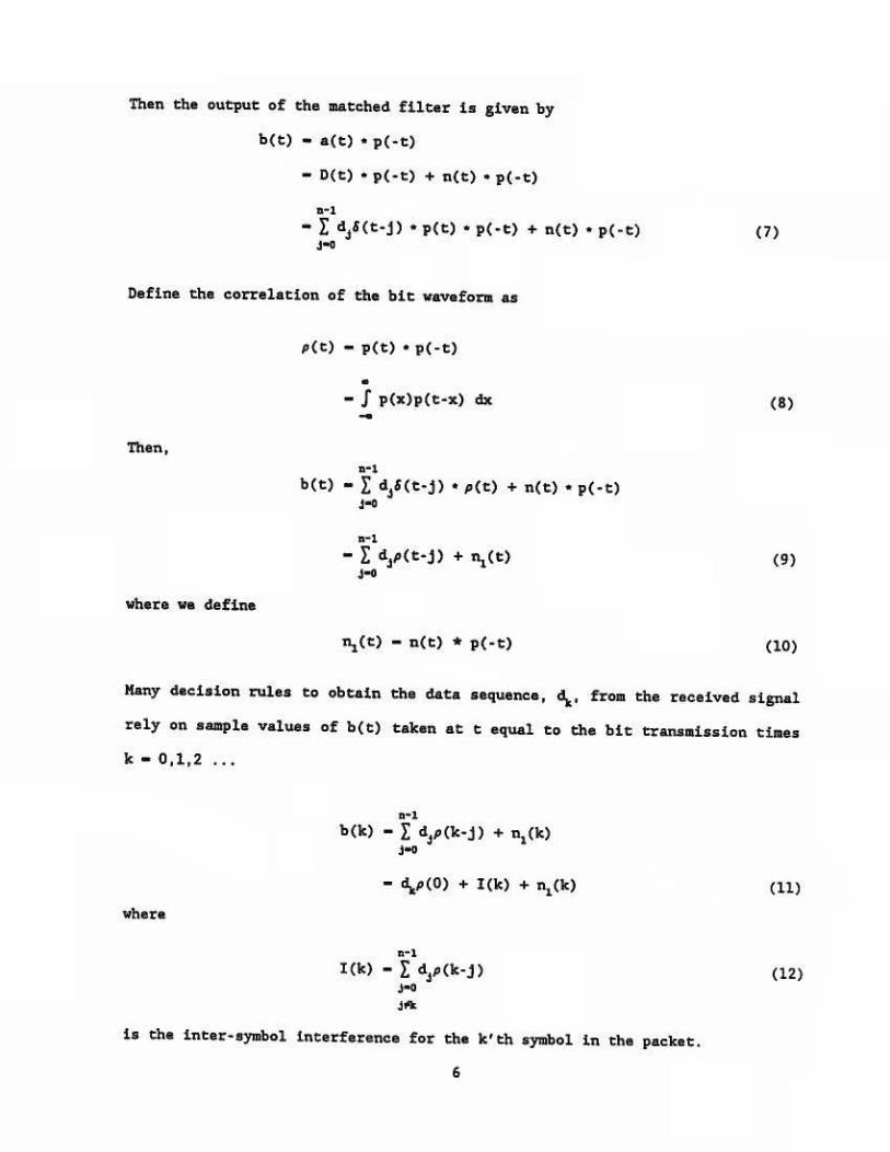
Then the output of the matched filter is given by
b(t) • a(t) • p(-t)
• D(t) • p( ·t) + n(t) • p(•t)
11- 1
- r di(t-j). p(t). p(-t) + n(t). p(-t) J-0
Define the correlation of the bit wavefoJ:111 as
Then,
where we define
p(t) - p(t) • p(-t)
• • f p(x)p(t•X) dx -
11•1
b(t) - r di(t•j). p(t) + n(t). p(•t) J-0
11- 1
- r dJp(t•j) + nl(t) J-0
~Ct) - n(t) * p(-t)
(7)
(8)
(9)
(10)
Many decision rules to obtain the data sequence, '\• from the received signal
rely on sample values of b(t) taken at t equal to the bit transmission times
k • 0,1,2 ...
where
D•l
b<k> - r dJp<k-j > • ~ ck> J-0
• '\P(O) + I(k) + ~(k)
n·l
I(k) • L dJp(lt· j) J-0 Jtlk
is the inter-symbol interference for the k'th S}'1llbol in the packet.
6
{11)
(12)

Defbte.
• :P(f) - f p(t) np( •f.1:i>t) dt: (1:3) -
tlhere. ~ - 2.ff'f. Then th e.n.ergy per bit ls
• 2 • 2 _ ~ - Ip (t) dt - I IF(f) I df (14) - -
and the mean square bam:lridth of the pulse waveform p(t.) is
• I f 2 IP(f) 12 df
Bz• -p • J (P(f) l2df -.j,(O) .. (15) I (2,r) ~
Not.e t:hat. the numarator of the above expresai011 for 1112 • 1:he mean square
bandwidth of the pul.se waveform. p(t) t is proport:ional to t::be en.e.rgy per
bit, ~. so that BP2 ia independent of ~ ·
L•t v.s fix n.. the numbe'l' of bics in the :pack•t used to prov.ide
synchronization. lnf'ot:mation. Then, if" N0 is tha power spectral density of
the :noise,, E;,/N0 and B,2 prO"V"id.• two easuras of th• quality of the packet
dececCion and synebroni:z.ati on ph.aa of the rece'iver (15 .16 ,17} . Once the
p&cket detection and syncbronizae:ton phase is complete, if the bits ill Che
packet are de.t:ected. independenclyt E;IN0 proitides a mea.su::re of the qua.lit.y
o.f th• signal det:e.c.tion phase of tbe rec=eiv•r (18J.
7

2.2 Spreadf.n1 Sequences
In order to achieve the time spreading of the packets discussed in section
1.2 wa use binary sequences with low autocorrelation properties, such as
Barker sequences [19,20}. Defina a binary sequence of length r as
j...0,1 ... r·l (16)
and a time invariant linear operator (spreader) corresponding to the
sequence sj with an impulse response function
rl
•<t> - r •,'<t·J> J-0
Define the correlation of a(t) as
O'{t) - s(t) • a( •t)
• - J s(x) a(x+t) dx -
,:-1
- E O'i<t·j> J•l•r
Where
In the case of Barker sequences,
for j•O
and
for j...O
8
(17)
(18)
(19)
(20a)
(20b)
Barker sequences are lcnovn only for th• ca••• of r•2,3,4,5,7,ll and 13, but
binary saquances of othar length• with good valua• of jc,JI for uaa in Spread
ALOHA channel• aa wall aa efficient methods of aaarchln1 for auch sequences
have baan obtained by U (20).
3 . Sl'UAJ> Al.0114
A• explained in section 1 . 2 , the lov duty cycle ALOHA channel shown in
Figure l can be waed in VSAT nat:vork.a with one aajor theoretical advanta1e
(it can achieve the Shannon bound) and ona overriding practical disadvantage
(it aay require an unreal1at1cally high valua of peak power out of the aaall
aperture earth atation). In this aaction va modify the algnab in the low
duty cycle ALOHA channel ao that the diaadvantage of high peak povar la
elialnatad vhila at the ••• tjae Ei,JN0 and B, z, the two meaaurea of signal
quality defined in section 2 .1 reaaln unchanaed. We call this modification
•spread ALOHA", and our raaults indicate that the performance of Spread
ALOHA la the aae aa that of l ow duty cycle ALOHA vhila the parforaanc• of
the latter la th• beat poaalbla for a given average power and a given
channal bandwidth.
The aodlficatlon va use 1• a natural one --- va take tba packets ahovn ln
Figura l and spread thaa in tlae. Such tlae apraadlng can ba done in a
nuabar of waya, but the aethoda ve augge.at have the property that th•
spreading leave• both Ei,JN0 4nd B,2 unchanged and at the •••• time the
spreading doaa not ~act the probability of packet overlap at the output of
the detector . If the satellite channel is operated in a linear mode, th•
increased channel overlap vlll not affect the operation of the ALOHA
channel. In aactiona 3.1 and 3. 2 ve describe tvo poasible method• for
apruding the packet in time, called bit spreading and chip apreadin& ,
9

3 .1 Bit: Sprea4 AI.OBA
For Bit Spread ALOHA pac.ket:s ve start with equation (3) and delay t:he
transmissi.on. of each bit by r units of: time. That: i•t lee the transiJDitted
packet be
nwl
D.(1:) • }: 4Jp(t:•rj) ,, .. and, following the development. of equations (4) aud (5)
n.~1.
Dl'(t) - I di {t•rj) * p(1:) rt
(2.1)
,(22)
As before we can represent Di:(-C) as the output of a time invariant linea.r
1operator with impulse response p(t) • lilhan the input ·is
11.•l
d.<c> .. I di<e-rJ> J-o
p(e) I i'1p.re 3 ; The senecnd racket •• ·ch• Outpu.c of a Linear Filter
(23)
We refer to the packet D~(t) as the stretched packet. And we produce ehe
apread. packet we wane by passing the s ·uecched packac ch.rough a epreade: t a
ti e i.nvari.ane linear filter wtth impulse r••ponse equal to r *112 s(e) t as
given. in equation (17) •
I p(t) , __ »_:c_<_t:)_, __.1,,-1,a • (t) 1--D-• (_t_) _
Figure 4 = The Bi& S~ead Packet as the Ol!Jtput o£ Two Un.ear rutei:s
10

'?he fona of the .spread packet 1a now eaaily c:alculated aa
where
n.ce) - r"112 dr(t) * a(t) * p(t)
m·l • r Ci(t•j) * p(t)
j-0
C - r·l/J d 8 ., . -
(24)
(2S)
and er 1a the largeat integer leaa then or equal to j/r and /J is j modulo r
a: - U/rJ fJ • j IIC>d r
(26a)
(26b)
The binary random variable&, c.,, conatitute the •cbipa• of the Spread ALOHA
signal; more prec:.iaely, c:.., ia the /J'th chip of the a:'th da1:a bit of the
spread aignal. Since each bit of the original packet is c:.onverted tor
chips of the apread packet by the spreader, each chip 1a multiplied by r·l/Z
in order to maintain the same energy per bit before and after apreading.
Thua the peak power requirement of th• transmitter i s decre,ued by a factor
of r. Tiae spreading provides a mechanism for reduc:.ing the average power of
the transmitter to a level conaistent with a network of VSAT terminals while
maintaining a conatent value for the energy per bit.
Note that in contrast to conventional apread apectrwa for continuous
aignala, each packet in the Spread ALOHA channel ia spread by the aaae
binary sequence, s.,. Separation of packets from different users is
accomplished by means of tha ALOHA contention protocol rather than by the
c:.rosa-correlation of different apread.ing sequences. And in contrast to
11

conventional op•ration of an ALOHA ehannel the separation i.s not limited by
the ov•rlap of the tTaumitted packets in t.be channel~ bu.t by the overlap of
che.se "PUl•es ae 'Cha ou.tpu.t of a match.ad fil te:c.
fro . Figure: 4 wa see immed:lat:aly that the proble11 of detection of che bits
of the spread. pactac in th.e pre,aenc,a of AWGN baa bean radtaced to chat ,of the
unspread packet of Fi,gun 2. Ve naed only -replace p(t) in Figu-re 2 by the
convolution of p(t) an.d s(t) in Figure 4. 'then for the sprea.d case the
spread ucched filter is •hown in Figure 5.
a(t) - a. (t) + n(t) p(-t) 1 ..... __., r·"'•(·t) l•--b(_c_> __
Figure 5: Input and Output of the Bit Spl:'ead Matched Filter
low following th• development used in equation (7) we have
b (t) - r -111 [a(i:) • p( • t) • s(-t) J
• r·112ro. (t) • p(-:t:) "' 8( • t)J + r · 1121n(t) • p(•t) • s(-e))
- r·1[dz(t) • s(t) • s.(•t) • p(t) • p(•t)J + r·112(n(t) • p(•t) • •(-t)]
- r-1(4Z'(t) • a(t) • p (1:) J + ~(t) (27)
where we define
(28)
Using (18) ~md (23). we can expand b(t) 1 the OUt;put: of the matched filter in
equacion. (27)
11-1 r--1 b(t) - r-1 I d3&(1:•Tj) * I c,J&(t•j) * p(~) + Ui(t)
J""O ~·r
12
nrl
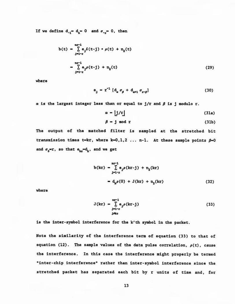
b(t) - r ei(t•j) • p(t) + n.i(t) J•l•z
nr-1
- r eJp(t·j> + n.i<t> J•1~
(29)
where
(30)
a is the largest integer le•• than or equal to j/r and Pis j modulo r.
a - 1)/rj (31a)
P • j mod r (31b)
The output of the matched filter is a1111pled at the stretched bit
transmission tillles t-kr, where lt-0,l,2
and is0•r, so that ;..,~. and we get
n•l. At these sanple points p-o
where
nr-1
b(kr) - r eJp(kr•j) + n.&(kr) J•1•,:
• y(O) + J(lcr) + n.&Ckr)
Dr-1 J(kr) - r eJp(kr•j)
J•1•r
J-
i• the inter-symbol interference for the k'th symbol in the packet.
(32)
(33)
Note the similarity of the interference term of equation (33) to that of
equation (12). The sample values of the data pulse correlation, p(t), cause
the interference. In this case the interference might properly be termed
"inter-chip interference• rather than inter-symbol interference since the
stretched packet has separated each bit by r units of time and, for
13
reasonably shaped pulses, p(t), this will eliainate the possibility of inter•
symbol interference. And even in those cases where the sample values of
p(t) are not negligible note that the coefficients eJ as given in equation
(30) decrease as r"1. Thia means that the interference cawied by adjacent
chips in Bit Spread ALOHA will be considerably lass than that caused by
adjacent bits in unspread packets.
Finally wa note that packet samples utilized by a matched filter detector of
Data Spread ALOHA packets are talten at intervals of r units of ti.lie. In the
caae of the AYGN channel asaUllled, packets which overlap in the channel can
still be detected correctly as long as all samples of each of the two
packets are separated by a single chip interval, taken as a unit of tiae .
Thus the total period of vulnerability in this unslotted Spread ALOHA
channel is twice the packet length, just as in a conventional unslotted
ALOHA channel. The only difference in this case is that the period of
vulnerability is broken up into 2n-l slllSll subintervals.
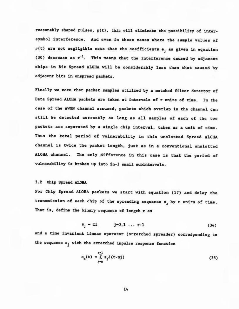
3.2 Chip Spread ALOHA
For Chip Spread ALOHA packets we start with equation (17) and delay the
transmission of each chip of the spreading sequence sJ by n units of time.
That is, define the binary sequence of length r as
j-0,1 ... r-1 (34)
and a time invariant linear operator (stretched spreader) corresponding to
the sequence sj with the stretched i:mpulse response function
rl
• n(t) - r •,&<t-nj) j-0
14
(35)
Define the correla·tion. af s ( t) as n. '
~1 - I o'.i'&(e-nj) (36)
.t•l-z
liihere the ~J are defined in equation (19)
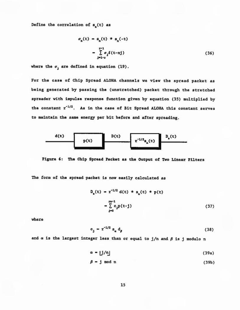
For the case of Chip Sprea.d ALOHA channels we view t:he spraad packet: as
being gene.rated by passing: the (unseret:chad) packet through the stretched
spreader with impulae rasponsa func;:.tion given by equa.cion (35) aultf.plied by
the con.stanc r~11z. As in. the case of Bit Spread. ALOHA thls constant: serves
to ataintain :t:he same energy pet: bit: before and after spreading~
__ ._<_1:> __ I p(t) I D(t.) I I n0 (t) ____ .. r · 112an(t:) :
Figure 6: The Chip Spire&d hebt: a.a the oucpuc of Two Linear Filters
The form of th.a •pread packet: is now easily calcula ced: as
where
.n-1
- I e.,p<t·j> J-0
C - J:'~tJ:Z. S d j . II J
(37)
(38)
an.cl a is the larges:t integer less than or equal to j /n and fJ is j modulo n
0 • IJ/1!)
fJ - j mod tt
15
(39a)
(39b)

No t:.e that the re laci ve positions of a J and dJ are reversed from. those in. th.e
c::ase of Bit Spread ALOHA chaqaals. ?ha binary rando111. variable•, cJ ' again
con.s.titut:e th "chips'i of :cbe Spread ALOHA signal bu.t this t i me cJ is ch.a
et' th chip of the I' th data bit of the spread signal . Again spreading the
packet in time allows us to decrease the peak powec of the tra.mnaitter by a
factor of r for the .!li&ml!I v•G • and agaiU only Ona binary spreading S,eqUl!!l'l\C::e
is used so that. .separaeton of different uaers is acco111pU.shed by eb.e ALOHA
contention protocol rather ae'han by th.e cross-correlation. of d.i ff-erene
.spr,uding sequences.
From Flgure 6 we can construcc t:he chip spread mat ched. f'i l te·l:' as shown in
Figure. 7 .
a(t:) .• n. (1:) + n(t) p(-t) I I I b(t)
•---11 r ~112s 11(·t) • -----
P1gure 7: I'npu:t: and Output of the Chip Spre.acl lfatG.he.d Filter
andt following the development used for Bit Spread ALOHA
b(t) - r-112[a(t} • p( · t) • s11 ( - t)]
- r · 11d(t) 11 an(t) • p(t)] + n,(t) (40)
where we de.fine.
(41)
Now, using (5) and (36) , we c:a.n e,t·pa·nd b(t) , the output of the matched
filter in equation: ( 40) .
16

where
- [~(t•j) * p(t)] + t1z(t)
IU:·1
- r eJp(t• j) + t1z(t) J ..........
(42)
(43)
and o is the largest integer leas then or equal to j/n and pis j modulo n
a - tj/nj (44a)
p - j mod n (44b)
The output of the matched filter is aADpled at the tb1ea t-k, where
k-0,l,2 ... n•l. At these sample points -o and 0'0-r, ao that e-~· and we
get
where
m-1
b(k) - r aJp(k•j) + t1z(k) J--- ~p(O) + J(k) + t1z(k)
v-1
J(k) - i IIJp(k•j) J-Jl'lt
is the inter-symbol interference for the k'th symbol in the packet.
(45)
(46)
In this case the primary interference terms present at each sample have the
SAIi& coefficients as the interference terms for unspread packets, and the
interference suppression advantages shown for Sit Spread ALOHA do not exist
for Chip Spread ALOHA channels. The total period of vulnerability for Chip
Spread ALOHA is twice the packet length, just as in a conventional unslotted
ALOHA channel.
17

4. DISCUSSION
In section 3 we dascribed two methods of taking the packets in an unslottad
Al.ORA channel, stretching these packets in ti.me and obtaining what we call
Bit Spread and Chip Spread ALOHA packets. Our interest in such signals
originates in the fact that low duty cycle ALOHA packets in a VSAT network
can be shown to achieve the Shannon capacity bound, but at the price of
requiring unrealistically high peak power transmitters in the VSAT
ter111inals. Time spreading allows us to maintain th• same systea performance
while the peak power of the transmitters is decreased significantly.
4.1 DS/BPSlt Equivalence
The fot111 of signala obtained in a Spread ALOHA channel suggest the structure
of a conventional spread spectrum signal, and it is not hard to demonstrate
a for111al equivalence between Bit Spread ALOHA and the usual for111 of Direct
Sequence, Bi.nary Phase Shift Keyed (DS/BPl>'lC) signals [18,21}.
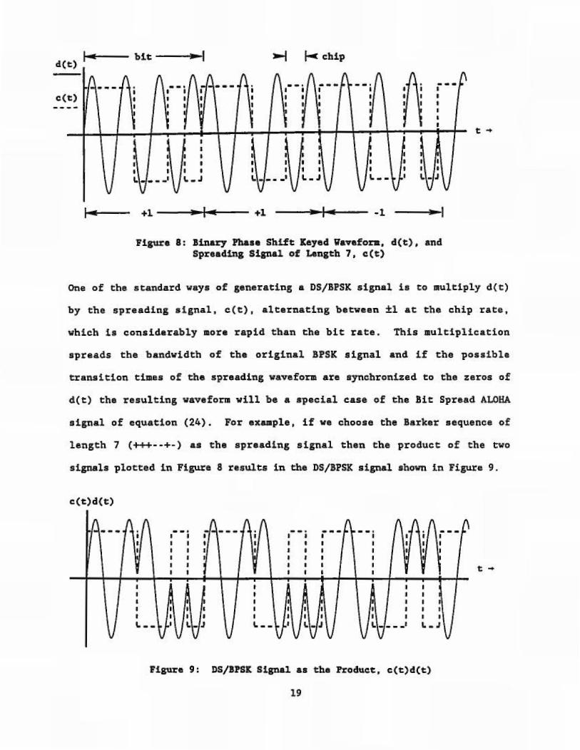
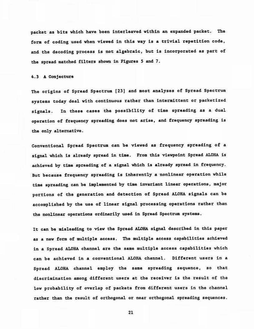
Consider the BPSK waveform
(47)
where the possible transitions of the binary phase modulation e•(t) are
synchronized to occur at the zeros of the carrier. For example, in Figure 8
we show the case where the possible tra.nsitions of 8.Ct) occur every seven
half cycles of the sinusoid carrier. And the same set of axes is used to
show a spreading signal of length seven, corresponding to the Barker
sequence, (+t+--+-).
18
d(t) ""'1 ... ..--- btt --• ... 1m1I --t 1-c chip
e(t) I
•
J i
I ' 1 •
--~ ... --. . ' I ' I ' . l I I I V.
••• \.. ,J VI
~- .t I. - J
+1~--~--~1--.... ---+1 -----......,1 .. ..-1~ .. 5 ......... - -1
__ ... I
• •
' '
--1
Fipre 81 Binaq' l'hase Shift: Keyed 'W&Yefon. d(t). and Spreading Signa1 of Lenatb 7. c(t)
t ..
On.e of the standard ways of generating a DS/BPSK signal ls to multi'ply d(t)
by the spreading signal, c(t) 1 alternacln.g between. ±1 a.t the chip rate.
vhi.ch is conslderably more rapid than the bit rate . This ault:iplication
spreads the bandwidth of the original BPSK t1gnal and. if ehe possible
:transition e:tmes o.f the spreading wav fol:111! are synchronized to the zeros of
d(e) th• 1:es1.a,lting waveform '\fill be a. special case of the !it Spread ALOHA
signal of equation. (24). For ex .... ple t i .f we choo.-e t:he :Barker sequence of
length 7 ( +++· ·+· ) as the spr•ading signal then ehe product of th.e two
signals plotted in. Figure 8 results in ch& DS/BPSK signal shown i.n Figure 9.
c(t.)d(t:)
---
• i
' ' I ..
--· --- ••• .. , .. - - -i ---• • • • ' • I I • • I • ' I i
• ' ' • • ' I
• • f • • •• I I
• • I
t • t • I
• ' ' - .. __ .. . .,
Pi~e 9: DS/11SK Signal as the h:oduct~ c(t)d(t)
19
t-t

The point here ia that precisely the same physical waveform can be viewed es
the result of modulation of a wideband carrier, composed of the product of a
sinusoid with a spreading or •paeuclorandom• waveform [9] , by a low bandwidth
signal composed of the data bits, or as the result of modulating a
conventional sinusoidal carrier by a much higher bandwidth signal composed
of the data chips. In the beleief that three points of view can sometiJUes
be more valuable than one, in section 4.2 we show that the same signal can
also be represented in terms of conventional algebraic coding theory.
4.2 Coding Equivalence
It is possible to show that the two forms of Spread ALOHA signals produced
in sections 3.1 and 3.2 are equivalent to a trivial form of algebraic coding
of the information digits of the packet. Let us represent the original
packet as the polynomial e(x) with coefficients from GF(2) in the usual way
(22}. Then a(x) may be represented as the product of the code generator
polynomial, g(x), with some other polynomial, d(x), representing the data of
the packet.
a(x) - d(x)g(x) (48)
Let s(x) be the polynomial of degree r-1, corresponding to the binary
spreading sequence of equation (17). Then Sit Spread ALOHA packets may be
represented by the polynomial
p(x) - d(x•)g(x')s(x) (49)
while Chip Spread ALOHA packets may be represented as the polynomial
p(x) - d(x)g(x)s(xn) (50)
In both cases the result follows from treating the individual chips of the
20
packet as bits which have been interleaved within an expanded packet. The
fora of coding used when viewed in this way is a trivial repetition code,
and the decoding process is not algebraic, but is incorporated as part of
the spread matched filters shown in Figures 5 and 7.
4.3 A Conjecture
The origins of Spread Spectrum (23] and most analyses of Spread Spectrum
systems today deal with continuous rather than intermittent or packetized
signals. In these cases the possibility of time spreading as a dual
operation of frequency spreading does not arise, and frequency spreading is
the only alternative .
Conventional Spread Spectrum can ba viewed as frequency spreading of a
signal which is already spread in tiae. From this viewpoint Spread ALOHA is
achieved by tiae spreading of a signal which is already spread in frequency.
But because frequency spreading is inherently a nonlinear operation while
time spreading can be implemented by time invariant linear operations, major
portions of the generation and detection of Spread ALOHA signals can be
accomplished by the use of linear signal processing operations rather than
the nonlinear operations ordinarily used in Spread Spectrum systems.
It can be iaisleading to view the Spread ALOHA signal described in this paper
as a new form of multiple access. The multiple access capabilities achieved
in a Spread ALOHA channel are the sanae multiple access capabilities which
can be achieved in a conventional ALOHA channel. Different users in a
Spread ALOHA channel employ the same spreading sequence, so that
discrimination among different users at the receiver is the result of the
low probability of overlap of packets from different users in the channel
rather than the result of orthogonal or near orthogonal spreading sequences.
21
The purpose of the spreading is to decrease the peak power required of the
transmitter and (in the case of Bit Spread ALOHA) perhaps to decrease inter
syiabol interference within the packet.
It has often been noted, but never been proved, that a general spread
spectrum channel with a processing gain of r can support up to about r/10
simultaneous accesses [7; p. 469]. For continuous users of such a channel
the data rate per user is usually about 1/r, so that the total maximun data
rate of the channel is approximately 0.10 of the maxilllum data rate for a
single user. In the case of a spread ALOHA channel the total period of
vulnerability to packet overlap at the output of the matched filter is twice
the width of the unspread packet, so that the maxilDWII throughput of such a
channel is the usual figure given for unslotted ALOHA throughput, or 1/2e
(0.186) times the maximum data rate for a single user. In practice it is
necessary to operate the ALOHA channel at some rate less than this to guard
against overloading the channel, and a figure of about 0.10 is often used.
We can also consider the combination of conventional multiple access Spread
Spectrum in addition to the use of Spread ALOHA in a multiple access
channel. For example, we might consider the use of several different
spreading sequences with good cross correlation properties to form what are
effectively several different orthogonal, or near orthogonal, channels
within one band of frequencies. As long as the spread packets sent using a
given spreading sequences do not produce inter channel interference in the
matched filters for the packet:JJ using the other spreading sequences we could
expect that different spreading sequences would allow us to increase the
throughput of the channel. Note that this does not contradict the fact that
Spread ALOHA achieves Shannon capacity since the separate channels using
different spreading sequences in this schema would transmit a higher total
22

power level in the channel. Since our interest is in networks with large
numbers of low duty cycle users where different spreading sequences might
introduce implementation problems, we have not analyzed this possibility.
But the considerations of the previous paragraph lead us to conjecture that
different spreading aequencaa would not lead to a higher overall throughput.
23
llEJ'EllENCES
l. N. Abramson, "The Throughput of Packet Broadcasting Channels,• IEEE Transactions on Communications, vol. COM-25, no. l, January 1977, pp. 117-128.
2. R. Binder, N. Abra11J1on, F. Kuo, A. Okinaka and D. Wax, •ALOHA Packet Broadcasting··· A Retrospect,• ProceedJ.ngs of the 1975 National Computer Conference, AFil'S Press, Montvale, New Jersey, Kay 1975, pp. 203-216
3. Edwin B. Parker , "Micro Earth Stations aa Personal Computer Accessories•, Proceedings of the IEEE, vol. 72, no. ll, November 1984, pp . 1526-1531.
4. Claude E. Shannon, "A Mathematical Theory of Collllllunie&tion, • Bell System Technical Journal, vol. 27, pp.379-423, 623-656, 1948.
5. John I . Capetenakia, "Th• Multiple Accesa Broadcast Channel: Protocol and Capacity Considerations,• IEEE Transactions on In.formation Theory, vol. IT-25, September 1979, pp. 505-515.
6. Boria S. Tsybakov, "Survey of USSR Contributions to Random Multiple• Access Comnunications,• IEEE TrBn$actions on Information Theory, vol. IT-31, no. 2, March 1985, pp.143-165.
7. Raymond L. Piclcholtz, Donald L. Schilling and Laurence B. Milstein, "Theory of Spread-Spectrum C0111111Unications ••• A Tutorial,• IEEE Transactions on Communications, vol. COM-30, no. 5, May 1982, pp. 855-884
8. Andrew J. Viterbi, •spread Spectrum Co1111unications - • • Myths and Realities,• IEEE Communications Hagazine, vol. 17, no. 3, Kay 1979, pp. 11· 18.
9. Robert A. Scholtz , "Th• Spread SpectrWI! Concept,• IEEE Tr4lls&ctions on Commun£cacions, vol. COM·25, no. 8, August 1977, pp. 748-755.
10. Jack K. Holmes, Coherent Spread Spectrum Systems, John Wiley & Sons, New York, 1982.
11. Michael B. Pursley, Dilip V. Sarawate and Wayne E. Stark, "Error Probability for Direct-Sequence Spread•Spectrwa Multiple-Access Communications ···Part I : Upper and Lower Bounds,• IEEE Transactions on Communications, vol. COM-30, no. 5, May 1982, pp. 975-984.
12. Nor11an F. Krasner, "Optimal Detection of Digitally Modulated Signal," IEEE Transactions on Co11munications, vol. COM-30, no. 5, Kay 1982, pp. 885· 895.
13. ~orge L. Turin, "An Introduction to Matched Filters," IRE Transactions on Information Theory, vol. lT-6, June 1960, pp. 311-329.
14. George L. Turin, "An Introduction to Digital Matched Filters,• Proceedings of the IEEE, vol. 64, no. 7, July 1976, pp. 1092-llll.
24

15. David J. Sakriaon, Communlcatlon Theory: Transmission of WaveLorms and Digital Information, John Wiley & Sous, New York, 1968.
16. L.A. Wainatein and V.D. Zubakov, Extraction of Signals from Nolse, translated by llichard A. Silverman, Prentice-Hall International, London, 1962.
17. Alan L. McBride and Andrew P. Saga, Optimum Estimat:ion of Bit Synchronization, IEEE Transactions on Aerospace and Electronic Sys tems, vol. AES-5, no. 3, May 1969, pp 525-536.
18. George R. Cooper and Clare D. KcGillem, Hodern Co111DW1icationa and Spread Spectrum, McGraw-Hill Book Company, New York, 1986.
19. R.H. Barker, •croup Synchronizing of llinary Digital Systems , • in Communication Theory, edited by W. Jackaon, Academic Presa, 1953, pp. 273-287.
20. Ping-Fai Li, "llinary Sequences with Low Autocorrelation,• ALOHA SYSTEH Techn.lcal Report B86·l, University of Hawaii, Honolulu, May 1986.
21. Rodger E. Ziemer and Roger L. Peterson, Digital ColllDIUnications and Spread Spectrum Syst81/J./I, Macmillan Publishing Company, New York, l98S.
22. Shu Lin, Error-Control Coding: Fundamentals and Apppllcatlons, PrenticeHall, Englewood Cliffs, New Jersey, 1983.
23. Robert A. Scholtz, "The Origins of Spread- Spectrua Communications,• IEEE Transactions on Comaainicationa, vol. COK·30, no. 5, Kay 1982, pp. 822-854.
2S


![Back Spread right Cover · Back Cover Back Spread left Back Spread right Cover. Front Spread left Front Spread right FOLDRite™ Template Master: AC-1 Accordion Fold [Side B] Title:](https://img.pdfslide.us/doc/110x75/5ffe964e74fe71462c35b447/back-spread-right-cover-back-cover-back-spread-left-back-spread-right-cover-front.jpg)