Embed Size (px)
Citation preview

Preventa™Safety SwitchesType XCSDM
Catalog Supplement to 9007CT0201
2009
Courtesy of Steven Engineering, Inc.-230 Ryan Way, South San Francisco, CA 94080-6370-Main Office: (650) 588-9200-Outside Local Area: (800) 258-9200-www.stevenengineering.com

Courtesy of Steven Engineering, Inc.-230 Ryan Way, South San Francisco, CA 94080-6370-Main Office: (650) 588-9200-Outside Local Area: (800) 258-9200-www.stevenengineering.com
2
1
4
5
6
7
8
9
10
2
1
4
5
6
7
8
9
10
1
Contents Safety detection solutions
Non-contact safety interlock switches
Non-contact safety interlock switches b Presentation, General characteristics . . . . . . . . . . . . . . . . . . . . . . . . . . . . . . . . . .2 b Plastic, v pre-cabled . . . . . . . . . . . . . . . . . . . . . . . . . . . . . . . . . . . . . . . . . . . . . . . . . . . . . . .4 v connector on pigtail . . . . . . . . . . . . . . . . . . . . . . . . . . . . . . . . . . . . . . . . . . . . . . . .5 b Accessories . . . . . . . . . . . . . . . . . . . . . . . . . . . . . . . . . . . . . . . . . . . . . . . . . . . . . .6
Non-contact safety interlock systems b Presentation, General characteristics . . . . . . . . . . . . . . . . . . . . . . . . . . . . . . . . .14 b Plastic, solid-state PNP type output, v Pre-cabled connection . . . . . . . . . . . . . . . . . . . . . . . . . . . . . . . . . . . . . . . . . . . .16 v M12 connector connection . . . . . . . . . . . . . . . . . . . . . . . . . . . . . . . . . . . . . . . . .17 b Accessories . . . . . . . . . . . . . . . . . . . . . . . . . . . . . . . . . . . . . . . . . . . . . . . . . . . . .18
1
Schneider Electric ®, the Schneider Electric logo, and Preventa™ are trademarks or registered trademarks of Schneider Electric .Other trademarks used herein are the property of their respective owners .
Courtesy of Steven Engineering, Inc.-230 Ryan Way, South San Francisco, CA 94080-6370-Main Office: (650) 588-9200-Outside Local Area: (800) 258-9200-www.stevenengineering.com
2
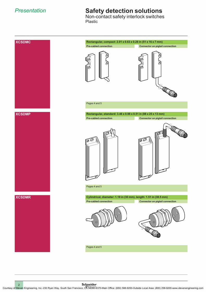
Safety detection solutionsNon-contact safety interlock switchesPlastic
XCSDMC Rectangular, compact: 2.01 x 0.63 x 0.28 in (51 x 16 x 7 mm)Pre-cabled connection Connector on pigtail connection
Pages 4 and 5
XCSDMP Rectangular, standard: 3.46 x 0.98 x 0.51 in (88 x 25 x 13 mm)Pre-cabled connection Connector on pigtail connection
Pages 4 and 5
XCSDMR Cylindrical, diameter: 1.18 in (30 mm), length: 1.51 in (38.5 mm)Pre-cabled connection Connector on pigtail connection
Pages 4 and 5
Presentation
1
2
4
5
6
7
8
9
10
Courtesy of Steven Engineering, Inc.-230 Ryan Way, South San Francisco, CA 94080-6370-Main Office: (650) 588-9200-Outside Local Area: (800) 258-9200-www.stevenengineering.com
3
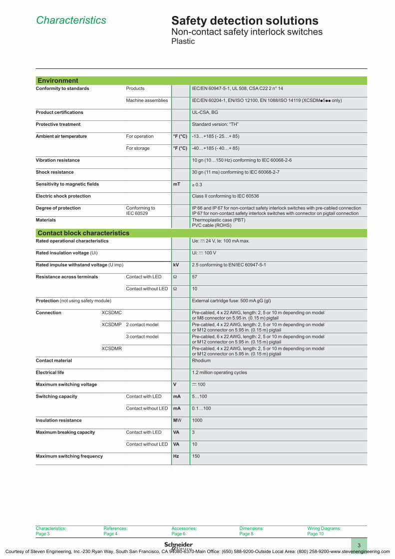
Safety detection solutionsNon-contact safety interlock switchesPlastic
EnvironmentConformity to standards Products IEC/EN 60947-5-1, UL 508, CSA C22 2 n° 14
Machine assemblies IEC/EN 60204-1, EN/ISO 12100, EN 1088/ISO 14119 (XCSDMp5pp only)
Product certifications UL-CSA, BG
Protective treatment Standard version: “TH”
Ambient air temperature For operation °F (°C) -13…+185 (- 25…+ 85)
For storage °F (°C) -40…+185 (- 40…+ 85)
Vibration resistance 10 gn (10…150 Hz) conforming to IEC 60068-2-6
Shock resistance 30 gn (11 ms) conforming to IEC 60068-2-7
Sensitivity to magnetic fields mT ≥ 0.3
Electric shock protection Class II conforming to IEC 60536
Degree of protection Conforming to IEC 60529
IP 66 and IP 67 for non-contact safety interlock switches with pre-cabled connectionIP 67 for non-contact safety interlock switches with connector on pigtail connection
Materials Thermoplastic case (PBT)PVC cable (ROHS)
Contact block characteristicsRated operational characteristics Ue: c 24 V, Ie: 100 mA max.
Rated insulation voltage (Ui) Ui: c 100 V
Rated impulse withstand voltage (U imp) kV 2.5 conforming to EN/IEC 60947-5-1
Resistance across terminals Contact with LED W 57
Contact without LED W 10
Protection (not using safety module) External cartridge fuse: 500 mA gG (gl)
Connection XCSDMC Pre-cabled, 4 x 22 AWG, length: 2, 5 or 10 m depending on modelor M8 connector on 5.95 in. (0.15 m) pigtail
XCSDMP 2 contact model Pre-cabled, 4 x 22 AWG, length: 2, 5 or 10 m depending on modelor M12 connector on 5.95 in. (0.15 m) pigtail
3 contact model Pre-cabled, 6 x 22 AWG, length: 2, 5 or 10 m depending on modelor M12 connector on 5.95 in. (0.15 m) pigtail
XCSDMR Pre-cabled, 4 x 22 AWG, length: 2, 5 or 10 m depending on modelor M12 connector on 5.95 in. (0.15 m) pigtail
Contact material Rhodium
Electrical life 1.2 million operating cycles
Maximum switching voltage V c 100
Switching capacity
Contact with LED mA 5…100
Contact without LED mA 0.1…100
Insulation resistance MW 1000
Maximum breaking capacity Contact with LED VA 3
Contact without LED VA 10
Maximum switching frequency Hz 150
Characteristics:Page 3
References:Page 4
Accessories:Page 6
Dimensions:Page 8
Wiring Diagrams:Page 10
Characteristics
1
2
4
5
6
7
8
9
10
Courtesy of Steven Engineering, Inc.-230 Ryan Way, South San Francisco, CA 94080-6370-Main Office: (650) 588-9200-Outside Local Area: (800) 258-9200-www.stevenengineering.com
4
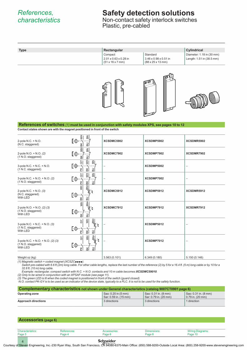
Safety detection solutionsNon-contact safety interlock switches Plastic, pre-cabled
Type Rectangular CylindricalCompact Standard Diameter: 1.18 in (30 mm)2.01 x 0.63 x 0.28 in (51 x 16 x 7 mm)
3.46 x 0.98 x 0.51 in (88 x 25 x 13 mm)
Length: 1.51 in (38.5 mm)
References of switches (1) must be used in conjunction with safety modules XPS, see pages 10 to 12Contact states shown are with the magnet positioned in front of the switch
BNBU
WH
BK
2-pole N.C. + N.O.(N.C. staggered)
XCSDMC5902 XCSDMP5902 XCSDMR5902
WH
BK
BNBU
2-pole N.O. + N.O. (2)(1 N.O. staggered)
XCSDMC7902 XCSDMP7902 XCSDMR7902
BUBNG
YPK
WH
BK
3-pole N.C. + N.C. + N.O.(1 N.C. staggered)
– XCSDMP5002 –
BUBN
BKW
H
GY
PK
3-pole N.C. + N.O. + N.O. (2)(1 N.O. staggered)
– XCSDMP7002 –
BKW
H
BN
BU
+ 2-pole N.C. + N.O. (3)(N.C. staggered)With LED
XCSDMC5912 XCSDMP5912 XCSDMR5912
BKW
H
BN
BU
+ 2-pole N.O. + N.O. (2) (3)(1 N.O. staggered)With LED
XCSDMC7912 XCSDMP7912 XCSDMR7912
PK
GY
WH
BK
BN
B
U
+ 3-pole N.C. + N.C. + N.O. (3)(1 N.C. staggered)With LED
– XCSDMP5012 –
PK
GY
WH
BK
BN
B
U
+ 3-pole N.C. + N.O. + N.O. (2) (3)(1 N.O. staggered)With LED
– XCSDMP7012 –
Weight oz (kg) 3.563 (0.101) 6.349 (0.180) 5.150 (0.146)(1) Magnetic switch + coded magnet (XCSZCpppp).
Switch pre-cabled with 6.6 ft.(2m) long cable. For other cable lengths, replace the last number of the reference (2) by 5 for a 16.4 ft. (5 m) long cable or by 10 for a 32.8 ft. (10 m) long cable. Example: rectangular, compact switch with N.C. + N.O. contacts and 10 m cable becomes XCSDMC59010.
(2) Only to be wired in conjunction with an XPSAF module (see page 11).(3) The green LED is lit when the coded magnet is positioned in front of the switch (guard closed).·N.O. contact PK-GY is to be used as an indicator of the device state, typically to a PLC. It is not to be used for the safety function.
Complementary characteristics not shown under General characteristics (catalog 9007CT0901 page 6)Operating zone Sao: 0.20 in (5 mm)
Sar: 0.59 in. (15 mm)Sao: 0.31 in. (8 mm)Sar: 0.79 in. (20 mm)
Sao: 0.31 in. (8 mm)0.79 in. (20 mm)
Approach directions 3 directions 3 directions 1 direction
Accessories (page 6)
Characteristics:Page 3
References:Page 4
Accessories:Page 6
Dimensions:Page 8
Wiring Diagrams:Page 10
References, characteristics
1
2
4
5
6
7
8
9
10
Courtesy of Steven Engineering, Inc.-230 Ryan Way, South San Francisco, CA 94080-6370-Main Office: (650) 588-9200-Outside Local Area: (800) 258-9200-www.stevenengineering.com
5
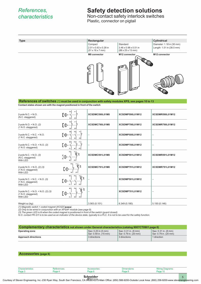
Safety detection solutionsNon-contact safety interlock switchesPlastic, connector on pigtail
Type Rectangular CylindricalCompact Standard Diameter: 1.18 in (30 mm)2.01 x 0.63 x 0.28 in (51 x 16 x 7 mm)
3.46 x 0.98 x 0.51 in (88 x 25 x 13 mm)
Length: 1.51 in (38.5 mm)
M8 connector M12 connector M12 connector
References of switches (1) must be used in conjunction with safety modules XPS, see pages 10 to 13Contact states shown are with the magnet positioned in front of the switch
13
24
2-pole N.C. + N.O.(N.C. staggered)
XCSDMC590L01M8 XCSDMP590L01M12 XCSDMR590L01M12
13
24
2-pole N.O. + N.O. (2)(1 N.O. staggered)
XCSDMC790L01M8 XCSDMP790L01M12 XCSDMR790L01M12
13
24
67
3-pole N.C. + N.C. + N.O.(1 N.C. staggered)
– XCSDMP500L01M12 –
13
24
67
3-pole N.C. + N.O. + N.O. (2)(1 N.O. staggered)
– XCSDMP700L01M12 –
13
24
2-pole N.C. + N.O. (3)(N.C. staggered)With LED
XCSDMC591L01M8 XCSDMP591L01M12 XCSDMR591L01M12
13
24
2-pole N.O. + N.O. (2) (3)(1 N.O. staggered)With LED
XCSDMC791L01M8 XCSDMP791L01M12 XCSDMR791L01M12
13
24
67
3-pole N.C. + N.C. + N.O. (3)(1 N.C. staggered)With LED
– XCSDMP501L01M12 –
13
24
67
3-pole N.C. + N.O. + N.O. (2) (3)(1 N.O. staggered)With LED
– XCSDMP701L01M12 –
Weight oz (kg) 3.563 (0.101) 6.349 (0.180) 5.150 (0.146)(1) Magnetic switch + coded magnet (XCSZCpppp).(2) Only to be wired in conjunction with an XPSAF module (see page 9).(3) The green LED is lit when the coded magnet is positioned in front of the switch (guard closed).N.O. contact PK-GY is to be used as an indicator of the device state, typically to a PLC. It is not to be used for the safety function.
Complementary characteristics not shown under General characteristics (catalog 9007CT0901 page 6)Operating zone Sao: 0.20 in (5 mm)
Sar: 0.59 in. (15 mm)Sao: 0.31 in. (8 mm)Sar: 0.79 in. (20 mm)
Sao: 0.31 in. (8 mm)Sar: 0.79 in. (20 mm)
Approach directions 3 directions 3 directions 1 direction
Accessories (page 6)
Characteristics:Page 3
References:Page 4
Accessories:Page 6
Dimensions:Page 8
Wiring Diagrams:Page 10
References, characteristics
1
2
4
5
6
7
8
9
10
Courtesy of Steven Engineering, Inc.-230 Ryan Way, South San Francisco, CA 94080-6370-Main Office: (650) 588-9200-Outside Local Area: (800) 258-9200-www.stevenengineering.com
6
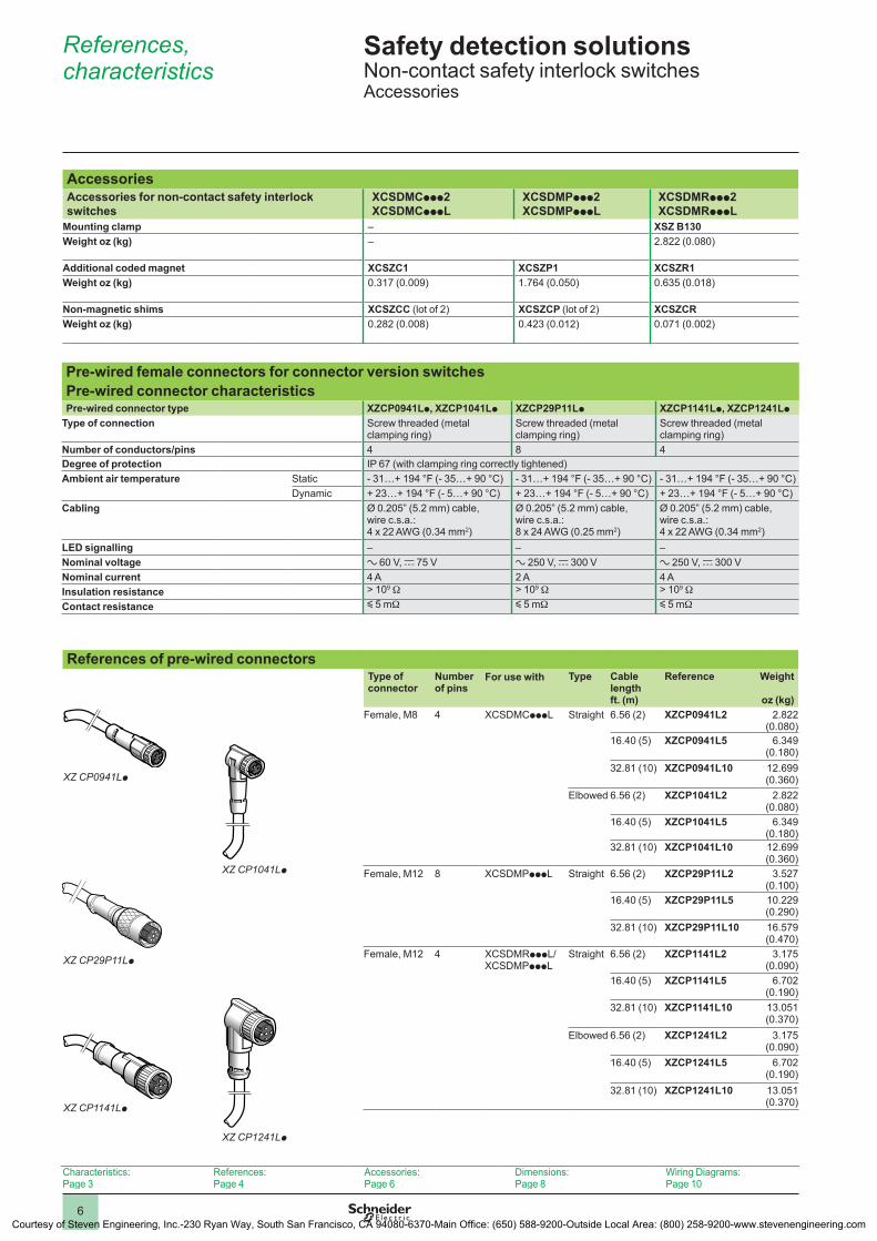
Safety detection solutionsNon-contact safety interlock switchesAccessories
AccessoriesAccessories for non-contact safety interlock switches
XCSDMCppp2XCSDMCpppL
XCSDMPppp2XCSDMPpppL
XCSDMRppp2XCSDMRpppL
Mounting clamp – XSZ B130Weight oz (kg) – 2.822 (0.080)
Additional coded magnet XCSZC1 XCSZP1 XCSZR1Weight oz (kg) 0.317 (0.009) 1.764 (0.050) 0.635 (0.018)
Non-magnetic shims XCSZCC (lot of 2) XCSZCP (lot of 2) XCSZCRWeight oz (kg) 0.282 (0.008) 0.423 (0.012) 0.071 (0.002)
Pre-wired female connectors for connector version switchesPre-wired connector characteristicsPre-wired connector type XZCP0941Lp, XZCP1041Lp XZCP29P11Lp XZCP1141Lp, XZCP1241Lp
Type of connection Screw threaded (metal clamping ring)
Screw threaded (metal clamping ring)
Screw threaded (metal clamping ring)
Number of conductors/pins 4 8 4Degree of protection IP 67 (with clamping ring correctly tightened)Ambient air temperature Static - 31…+ 194 °F (- 35…+ 90 °C) - 31…+ 194 °F (- 35…+ 90 °C) - 31…+ 194 °F (- 35…+ 90 °C)
Dynamic + 23…+ 194 °F (- 5…+ 90 °C) + 23…+ 194 °F (- 5…+ 90 °C) + 23…+ 194 °F (- 5…+ 90 °C)Cabling Ø 0.205” (5.2 mm) cable,
wire c.s.a.: 4 x 22 AWG (0.34 mm2)
Ø 0.205” (5.2 mm) cable, wire c.s.a.: 8 x 24 AWG (0.25 mm2)
Ø 0.205” (5.2 mm) cable, wire c.s.a.: 4 x 22 AWG (0.34 mm2)
LED signalling – – –Nominal voltage a 60 V, c 75 V a 250 V, c 300 V a 250 V, c 300 VNominal current 4 A 2 A 4 AInsulation resistance > 109 W > 109 W > 109 WContact resistance y 5 mW y 5 mW y 5 mW
References of pre-wired connectors
Type of connector
Number of pins
For use with Type Cable length ft. (m)
Reference Weight
oz (kg)Female, M8 4 XCSDMCpppL Straight 6.56 (2) XZCP0941L2 2.822
(0.080)16.40 (5) XZCP0941L5 6.349
(0.180)32.81 (10) XZCP0941L10 12.699
(0.360)Elbowed 6.56 (2) XZCP1041L2 2.822
(0.080)16.40 (5) XZCP1041L5 6.349
(0.180)32.81 (10) XZCP1041L10 12.699
(0.360)Female, M12 8 XCSDMPpppL Straight 6.56 (2) XZCP29P11L2 3.527
(0.100)16.40 (5) XZCP29P11L5 10.229
(0.290)32.81 (10) XZCP29P11L10 16.579
(0.470)Female, M12 4 XCSDMRpppL/
XCSDMPpppLStraight 6.56 (2) XZCP1141L2 3.175
(0.090)16.40 (5) XZCP1141L5 6.702
(0.190)32.81 (10) XZCP1141L10 13.051
(0.370)Elbowed 6.56 (2) XZCP1241L2 3.175
(0.090)16.40 (5) XZCP1241L5 6.702
(0.190)32.81 (10) XZCP1241L10 13.051
(0.370)
XZ CP0941Lp
5036
27
XZ CP1041Lp
5036
26
XZ CP29P11Lp
5346
40
XZ CP1141Lp
5633
52
XZ CP1241Lp
5036
30
Characteristics:Page 3
References:Page 4
Accessories:Page 6
Dimensions:Page 8
Wiring Diagrams:Page 10
References, characteristics
1
2
4
5
6
7
8
9
10
Courtesy of Steven Engineering, Inc.-230 Ryan Way, South San Francisco, CA 94080-6370-Main Office: (650) 588-9200-Outside Local Area: (800) 258-9200-www.stevenengineering.com
7
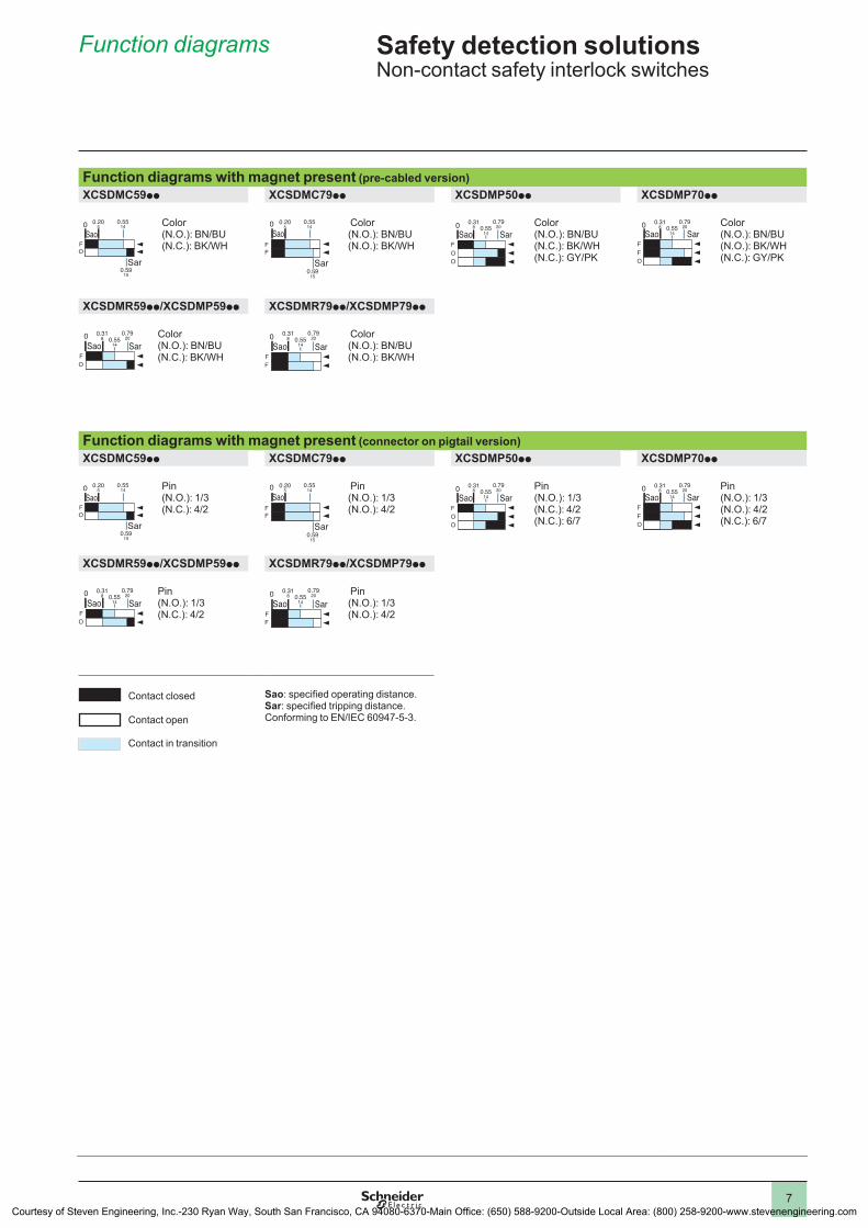
Safety detection solutionsNon-contact safety interlock switches
Function diagrams with magnet present (pre-cabled version)XCSDMC59pp XCSDMC79pp XCSDMP50pp XCSDMP70pp
Color (N.O.): BN/BU (N.C.): BK/WH
Color (N.O.): BN/BU (N.O.): BK/WH
Color (N.O.): BN/BU (N.C.): BK/WH (N.C.): GY/PK
Color (N.O.): BN/BU (N.O.): BK/WH (N.C.): GY/PK
XCSDMR59pp/XCSDMP59pp XCSDMR79pp/XCSDMP79pp
Color (N.O.): BN/BU (N.C.): BK/WH
Color (N.O.): BN/BU (N.O.): BK/WH
Function diagrams with magnet present (connector on pigtail version)XCSDMC59pp XCSDMC79pp XCSDMP50pp XCSDMP70pp
Pin (N.O.): 1/3 (N.C.): 4/2
Pin (N.O.): 1/3 (N.O.): 4/2
Pin (N.O.): 1/3 (N.C.): 4/2 (N.C.): 6/7
Pin (N.O.): 1/3 (N.O.): 4/2 (N.C.): 6/7
XCSDMR59pp/XCSDMP59pp XCSDMR79pp/XCSDMP79pp
Pin (N.O.): 1/3 (N.C.): 4/2
Pin (N.O.): 1/3 (N.O.): 4/2
Contact closed
Contact open
Contact in transition
Sao: specified operating distance.Sar: specified tripping distance.Conforming to EN/IEC 60947-5-3.
0Sao
Sar
FO
0.205
0.5514
0.5915
Sao
Sar
FF
0 0.205
0.5514
0.5915
0Sao Sar
F
OO
0.318 0.55
14
0.7920 0
Sao SarF
OF
0.318 0.55
14
0.7920
Sao SarFO
0 0.318 0.55
14
0.7920
Sao SarFF
0 0.318 0.55
14
0.7920
0Sao
Sar
FO
0.205
0.5514
0.5915
Sao
Sar
FF
0 0.205
0.5514
0.5915
0Sao Sar
F
OO
0.318 0.55
14
0.7920 0
Sao SarF
OF
0.318 0.55
14
0.7920
Sao SarFO
0 0.318 0.55
14
0.7920
Sao SarFF
0 0.318 0.55
14
0.7920
Function diagrams
1
2
4
5
6
7
8
9
10
Courtesy of Steven Engineering, Inc.-230 Ryan Way, South San Francisco, CA 94080-6370-Main Office: (650) 588-9200-Outside Local Area: (800) 258-9200-www.stevenengineering.com
8
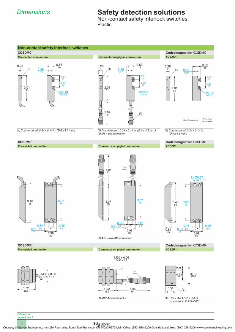
Safety detection solutionsNon-contact safety interlock switchesPlastic
Non-contact safety interlock switchesXCSDMC Coded magnet for XCSDMC Pre-cabled connection Connector on pigtail connection XCSZC1
(1) Counterbored: 0.24 x 0.14 in. (Ø 6 x 3.5 mm.) (1) Counterbored: 0.24 x 0.14 in. (Ø 6 x 3.5 mm.)(2) M8 4-pin connector.
(1) Counterbored: 0.24 x 0.14 in. (Ø 6 x 3.5 mm.)
XCSDMP Coded magnet for XCSDMPPre-cabled connection Connector on pigtail connection XCSZP1
(1) 4 or 6-pin M12 connector.
XCSDMR Coded magnet for XCSDMR Pre-cabled connection Connector on pigtail connection XCSZR1
(1) M12 4-pin connector. (1) 0.08 x Ø 0.17 (2 x Ø 4.3), countersunk: Ø 7.5 at 45°.
(1)0.28
7
2.0151
0.6316
0.4912.5
0.6316
0.318
2xØ1.342xØ 3.5
0.6316
0.318
0.287 (1)
(2)
0.6316
0.4912.5
5.94151
2.0151 2xØ1.34
2xØ 3.5
(1)0.28
7
2.0151
0.6316
0.4912.5
0.6316
0.318
2xØ1.342xØ 3.5
0.266.5
0.143.50.31
8 0.9825
3.0778
3.4688
0.266.5
0.143.50.31
8 0.9825
(1)
3.0778
3.0778
5.94151
0.5113
0.266.5
0.143.50.31
8 0.9825
3.0778
2x Ø0.172x Ø4.5
3.4688
M30 x 0.06M30 x 1.5
1.5238.5
(1)
M30 x 0.06M30 x 1.5
1.5238.5
5.94151
0.5113 (1)
0.6316
0.287
1.18
References:pages 4 and 5
Dimensions
1
2
4
5
6
7
8
9
10
INCHESMillimietersDual Dimensions:
Courtesy of Steven Engineering, Inc.-230 Ryan Way, South San Francisco, CA 94080-6370-Main Office: (650) 588-9200-Outside Local Area: (800) 258-9200-www.stevenengineering.com
9
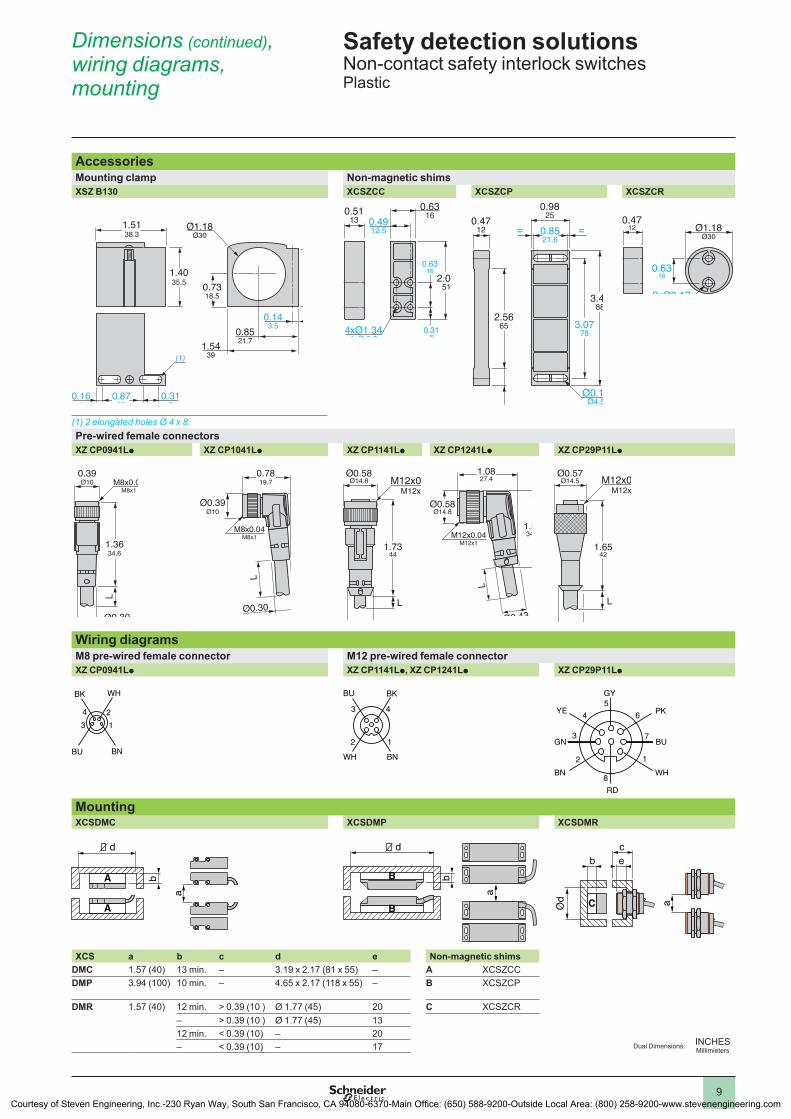
Safety detection solutionsNon-contact safety interlock switchesPlastic
AccessoriesMounting clamp Non-magnetic shimsXSZ B130 XCSZCC XCSZCP XCSZCR
(1) 2 elongated holes Ø 4 x 8.Pre-wired female connectorsXZ CP0941Lp XZ CP1041Lp XZ CP1141Lp XZ CP1241Lp XZ CP29P11Lp
Wiring diagramsM8 pre-wired female connector M12 pre-wired female connectorXZ CP0941Lp XZ CP1141Lp, XZ CP1241Lp XZ CP29P11Lp
MountingXCSDMC XCSDMP XCSDMR
XCS a b c d e Non-magnetic shimsDMC 1.57 (40) 13 min. – 3.19 x 2.17 (81 x 55) – A XCSZCCDMP 3.94 (100) 10 min. – 4.65 x 2.17 (118 x 55) – B XCSZCP
DMR 1.57 (40) 12 min. > 0.39 (10 ) Ø 1.77 (45) 20 C XCSZCR– > 0.39 (10 ) Ø 1.77 (45) 1312 min. < 0.39 (10) – 20– < 0.39 (10) – 17
1.5439
0.143.5
Ø1.18Ø30
0.8521.7
1.5138.3
(1)
0.318
0.164
0.8722
1.4035.5 0.73
18.5
1.2231
0.5113
2.0151
0.6316
0.318
4xØ1.344xØ 3.5
0.6316
0.4912.5
0.4511.5
0.4712 = =
3.0778
3.4688
Ø0.17Ø4.5
0.9825
2.5665
0.8521.6
0.4712
0.6316
2xØ0.172xØ4.3
Ø1.18Ø30
0.39Ø10
L
Ø0.30Ø7.5
M8x0.04M8x1
1.3634.6
Ø0.30Ø7.5
Ø0.39Ø10
L
M8x0.04M8x1
1.1027.9
0.7819.7
Ø0.58Ø14.8
Ø0.43Ø11
L
M12x0.04M12x1
1.7344
Ø0.43Ø11
L
M12x0.04M12x1
1.0827.4
1.3634.5
Ø0.58Ø14.8
Ø0.57Ø14.5
Ø0.43Ø11
L
M12x0.04M12x1
1.6542
4 23 1
BU
BK WH
BN
3 4
2 1
BU BK
WH BN 1
7
64
3
PK
BUGN
YE
2
BN WH
5
8
GY
RD
d
A
A
a
b B
B
d
a
b
C
cb
Ød a
e
Dimensions (continued), wiring diagrams, mounting
1
2
4
5
6
7
8
9
10INCHESMillimietersDual Dimensions:
Courtesy of Steven Engineering, Inc.-230 Ryan Way, South San Francisco, CA 94080-6370-Main Office: (650) 588-9200-Outside Local Area: (800) 258-9200-www.stevenengineering.com
10
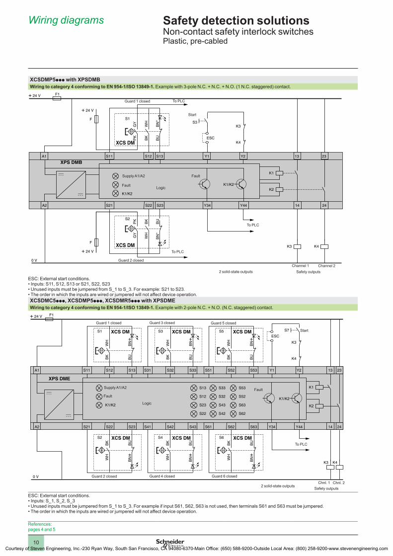
Safety detection solutionsNon-contact safety interlock switchesPlastic, pre-cabled
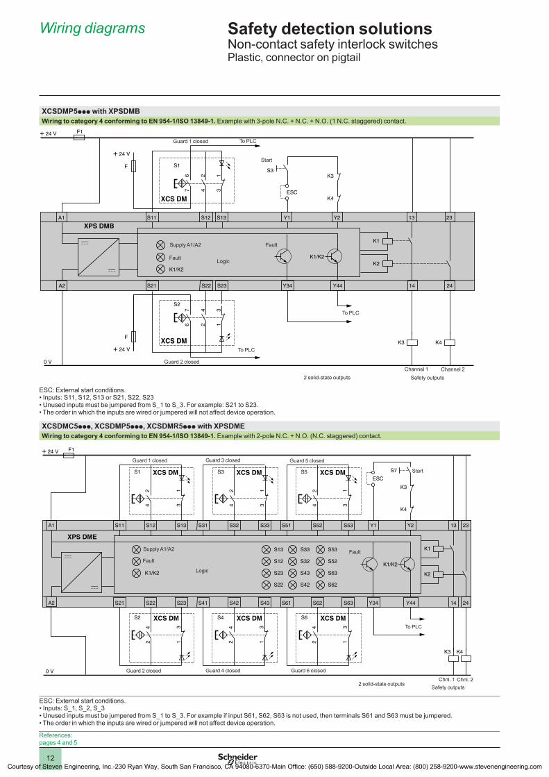
XCSDMP5ppp with XPSDMB Wiring to category 4 conforming to EN 954-1/ISO 13849-1. Example with 3-pole N.C. + N.C. + N.O. (1 N.C. staggered) contact.
ESC: External start conditions.• Inputs: S11, S12, S13 or S21, S22, S23• Unused inputs must be jumpered from S_1 to S_3. For example: S21 to S23.• The order in which the inputs are wired or jumpered will not affect device operation.XCSDMC5ppp, XCSDMP5ppp, XCSDMR5ppp with XPSDME Wiring to category 4 conforming to EN 954-1/ISO 13849-1. Example with 2-pole N.C. + N.O. (N.C. staggered) contact.
ESC: External start conditions.• Inputs: S_1, S_2, S_3• Unused inputs must be jumpered from S_1 to S_3. For example if input S61, S62, S63 is not used, then terminals S61 and S63 must be jumpered.• The order in which the inputs are wired or jumpered will not affect device operation.
A1 Y1 Y2 13S11 S13
K4
K3
K1
K3
K2 K1/K2
K4
A2 Y34 Y44 14
23
24S21 S22 S23
K1/K2
XPS DMBS12
S3
ESC
F1+ 24 V
0 V
S1
XCS DM
PK
GY
BK
WH
BU
BN
+
S2
XCS DM
GY
PK
WH
BK
BN
+B
U
+ 24 V
F
+ 24 V
F
Start
Logic
Supply A1/A2
Fault
Fault
Channel 1 Channel 2Safety outputs
To PLC
2 solid-state outputs
Guard 2 closed
Guard 1 closed
To PLC
To PLC
A1 Y1 Y2 13S11 S12 S13
S1 XCS DM XCS DM XCS DM
K4
K3
K1
K3
K2
K1/K2
BK
WH
BU
BN+
S31 S32 S33
S3
BK
WH
BU
BN+
S51 S52 S53
A2 Y34 Y44 14
23
K4
24S21 S22 S23 S41 S42 S43 S61 S62 S63
S13
S12
S23
S22
K1/K2
S53
S52
S63
S62
S33
S32
S43
S42
S5
BK
WH
BU
BN+
S2 XCS DM
XPS DME
WH
BK
BN+
BU
S4 XCS DM
WH
BK
BN+
BU
S6 XCS DM
WH
BK
BN+
BU
S7
ESC
F1+ 24 V
0 V
Start
Logic
Supply A1/A2
Fault
Fault
Chnl. 1 Chnl. 2Safety outputs
To PLC
2 solid-state outputs
Guard 2 closed
Guard 1 closed
Guard 4 closed Guard 6 closed
Guard 3 closed Guard 5 closed
References:pages 4 and 5
Wiring diagrams
1
2
4
5
6
7
8
9
10
Courtesy of Steven Engineering, Inc.-230 Ryan Way, South San Francisco, CA 94080-6370-Main Office: (650) 588-9200-Outside Local Area: (800) 258-9200-www.stevenengineering.com
11
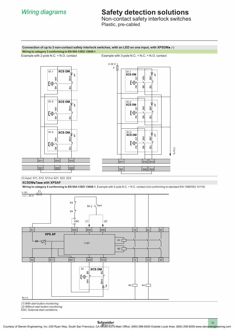
Safety detection solutionsNon-contact safety interlock switchesPlastic, pre-cabled
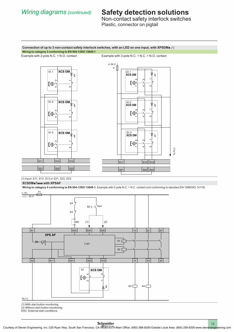
Connection of up to 3 non-contact safety interlock switches, with an LED on one input, with XPSDMp (1)Wiring to category 3 conforming to EN 954-1/ISO 13849-1
Example with 2-pole N.C. + N.O. contact Example with 3-pole N.C. + N.C. + N.O. contact
(1) Input: S11, S12, S13 or S21, S22, S23.
XCSDMp7ppp with XPSAFWiring to category 4 conforming to EN 954-1/ISO 13849-1. Example with 2-pole N.C. + N.C. contact (not conforming to standard EN 1088/ISO 14119)
(1) With start button monitoring.(2) Without start button monitoring.ESC: External start conditions.
S11 S12 S13
S1.3 XCS DM
BK
WH
BU
BN+
S1.2 XCS DM
BK
WH
BU
BN+
S1.1 XCS DM
BK
WH
BU
BN+
S21 S22 S23
S11 S12 S13
S21 S22 S23
S1.1XCS DM
PK
GY
BK
WH
BU
BN
+
S1.2XCS DM
PK
GY
BK
WH
BU
BN
+
S1.3XCS DM
PK
GY
BK
WH
BU
BN
+
+ 24 V
F
To P
LC
A1 13S33 S39
K1
K3
K2
K4
A2 14
23
24
33
34S11 S21 S22 S12
XPS AF
S34
F1+ L ( )
K4
K3 S2
ESC
N ( )
S1
T
XCS DM
WH
BK
BN+
BU
(1) (2)
Start
Logic
Wiring diagrams
1
2
4
5
6
7
8
9
10
Courtesy of Steven Engineering, Inc.-230 Ryan Way, South San Francisco, CA 94080-6370-Main Office: (650) 588-9200-Outside Local Area: (800) 258-9200-www.stevenengineering.com
12
Safety detection solutionsNon-contact safety interlock switchesPlastic, connector on pigtail
XCSDMP5ppp with XPSDMB Wiring to category 4 conforming to EN 954-1/ISO 13849-1. Example with 3-pole N.C. + N.C. + N.O. (1 N.C. staggered) contact.
ESC: External start conditions.• Inputs: S11, S12, S13 or S21, S22, S23• Unused inputs must be jumpered from S_1 to S_3. For example: S21 to S23.• The order in which the inputs are wired or jumpered will not affect device operation.
XCSDMC5ppp, XCSDMP5ppp, XCSDMR5ppp with XPSDME Wiring to category 4 conforming to EN 954-1/ISO 13849-1. Example with 2-pole N.C. + N.O. (N.C. staggered) contact.
ESC: External start conditions.• Inputs: S_1, S_2, S_3• Unused inputs must be jumpered from S_1 to S_3. For example if input S61, S62, S63 is not used, then terminals S61 and S63 must be jumpered.• The order in which the inputs are wired or jumpered will not affect device operation.
A1 Y1 Y2 13S11 S13
K4
K3
K1
K3
K2 K1/K2
K4
A2 Y34 Y44 14
23
24S21 S22 S23
K1/K2
XPS DMBS12
S3
ESC
F1+ 24 V
0 V
S1
XCS DM
76
42
31
S2
XCS DM
67
24
13
+ 24 V
F
+ 24 V
F
Start
Logic
Supply A1/A2
Fault
Fault
Channel 1 Channel 2Safety outputs
To PLC
2 solid-state outputs
Guard 2 closed
Guard 1 closed
To PLC
To PLC
A1 Y1 Y2 13S11 S12 S13
S1 XCS DM XCS DM XCS DM
K4
K3
K1
K3
K2
K1/K2
42
31
24
13
24
13
24
13
42
31
42
31
S31 S32 S33
S3
S51 S52 S53
A2 Y34 Y44 14
23
K4
24S21 S22 S23 S41 S42 S43 S61 S62 S63
S13
S12
S23
S22
K1/K2
S53
S52
S63
S62
S33
S32
S43
S42
S5
S2 XCS DM
XPS DME
S4 XCS DM S6 XCS DM
S7
ESC
F1+ 24 V
0 V
Start
Logic
Supply A1/A2
Fault
Fault
Chnl. 1 Chnl. 2Safety outputs
To PLC
2 solid-state outputs
Guard 2 closed
Guard 1 closed
Guard 4 closed Guard 6 closed
Guard 3 closed Guard 5 closed
References:pages 4 and 5
Wiring diagrams
1
2
4
5
6
7
8
9
10
Courtesy of Steven Engineering, Inc.-230 Ryan Way, South San Francisco, CA 94080-6370-Main Office: (650) 588-9200-Outside Local Area: (800) 258-9200-www.stevenengineering.com
13
Safety detection solutionsNon-contact safety interlock switchesPlastic, connector on pigtail
Connection of up to 3 non-contact safety interlock switches, with an LED on one input, with XPSDMp (1)Wiring to category 3 conforming to EN 954-1/ISO 13849-1
Example with 2-pole N.C. + N.O. contact Example with 3-pole N.C. + N.C. + N.O. contact
(1) Input: S11, S12, S13 or S21, S22, S23.
XCSDMp7ppp with XPSAFWiring to category 4 conforming to EN 954-1/ISO 13849-1. Example with 2-pole N.C. + N.C. contact (not conforming to standard EN 1088/ISO 14119)
(1) With start button monitoring.(2) Without start button monitoring.ESC: External start conditions.
S11 S12 S13
S1.3 XCS DM
42
31
S1.2 XCS DM
42
31
S1.1 XCS DM
42
31
S21 S22 S23
S11 S12 S13
S21 S22 S23
S1.1XCS DM
76
42
31
76
42
31
76
42
31
S1.2XCS DM
S1.3XCS DM
+ 24 V
F
To P
LC
A1 13S33 S39
K1
K3
K2
K4
A2 14
23
24
33
34S11 S21 S22 S12
XPS AF
S34
F1+ L ( )
K4
K3 S2
ESC
N ( )
S1
T
XCS DM
24
13
(1) (2)
Start
Logic
Wiring diagrams (continued)
1
2
4
5
6
7
8
9
10
Courtesy of Steven Engineering, Inc.-230 Ryan Way, South San Francisco, CA 94080-6370-Main Office: (650) 588-9200-Outside Local Area: (800) 258-9200-www.stevenengineering.com
14
1
2
4
5
6
7
8
9
10
2
1
4
5
6
7
8
9
10
14
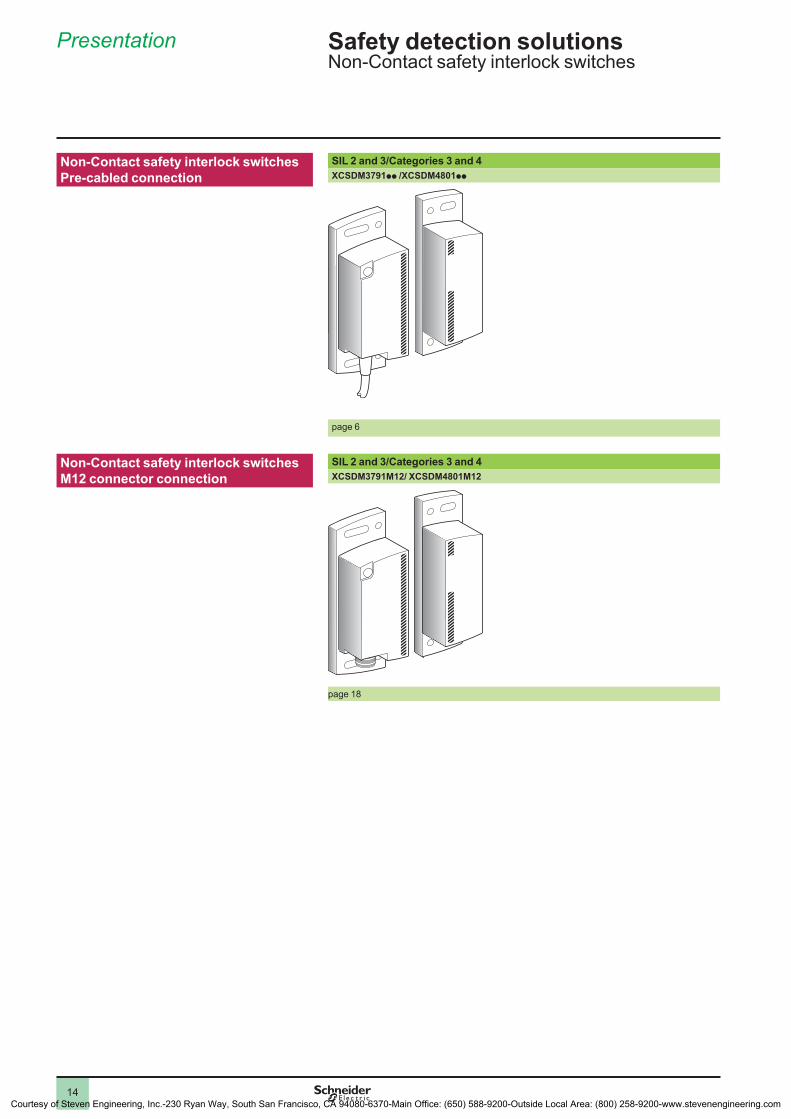
Non-Contact safety interlock switches Pre-cabled connection
SIL 2 and 3/Categories 3 and 4XCSDM3791pp /XCSDM4801pp
page 6
Non-Contact safety interlock switches M12 connector connection
SIL 2 and 3/Categories 3 and 4XCSDM3791M12/ XCSDM4801M12
page 18
Presentation
Safety detection solutionsNon-Contact safety interlock switches
Courtesy of Steven Engineering, Inc.-230 Ryan Way, South San Francisco, CA 94080-6370-Main Office: (650) 588-9200-Outside Local Area: (800) 258-9200-www.stevenengineering.com
15
1
2
4
5
6
7
8
9
10
2
1
4
5
6
7
8
9
10
15
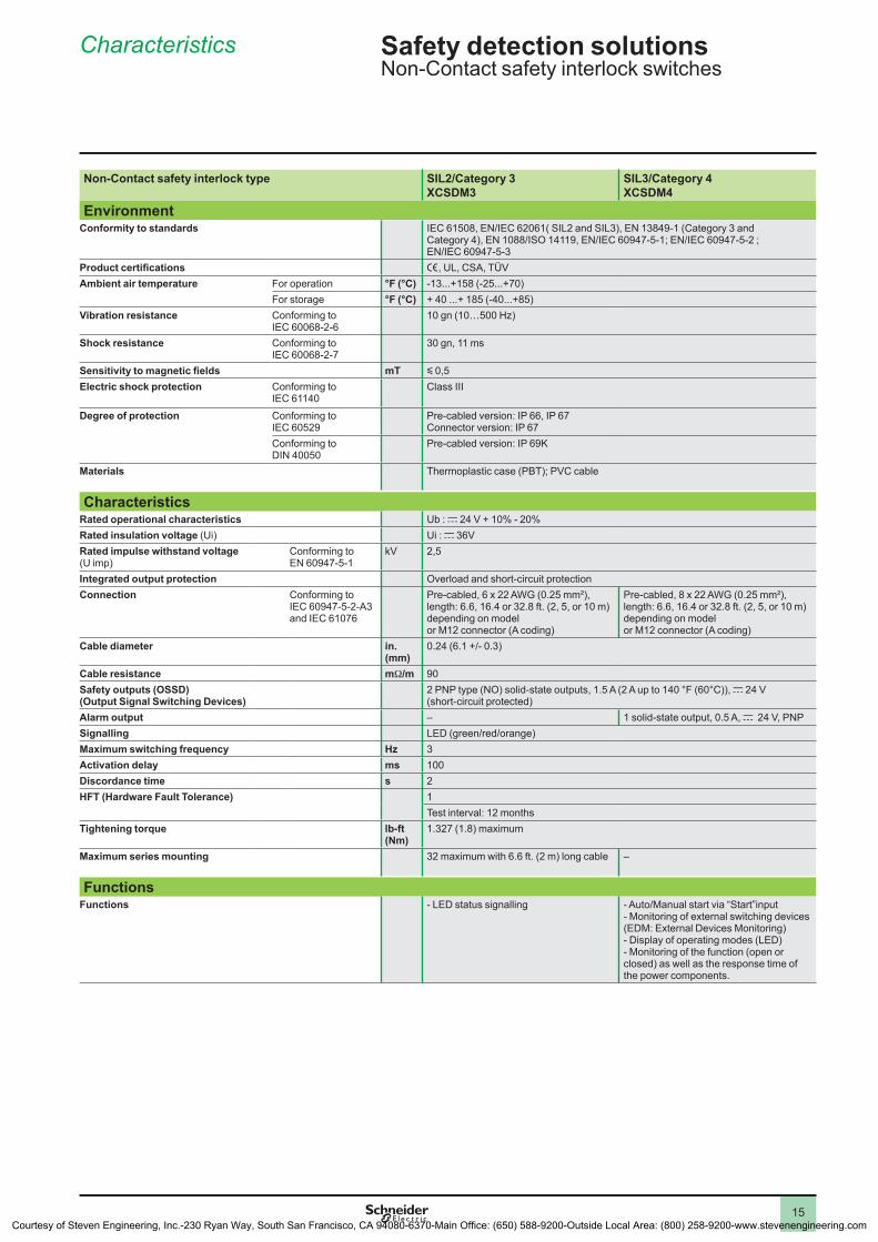
Non-Contact safety interlock type SIL2/Category 3 XCSDM3
SIL3/Category 4 XCSDM4
EnvironmentConformity to standards IEC 61508, EN/IEC 62061( SIL2 and SIL3), EN 13849-1 (Category 3 and
Category 4), EN 1088/ISO 14119, EN/IEC 60947-5-1; EN/IEC 60947-5-2 ; EN/IEC 60947-5-3
Product certifications e, UL, CSA, TÜVAmbient air temperature For operation °F (°C) -13...+158 (-25...+70)
For storage °F (°C) + 40 ...+ 185 (-40...+85)Vibration resistance Conforming to
IEC 60068-2-610 gn (10…500 Hz)
Shock resistance Conforming to IEC 60068-2-7
30 gn, 11 ms
Sensitivity to magnetic fields mT y 0,5Electric shock protection Conforming to
IEC 61140Class III
Degree of protection Conforming to IEC 60529
Pre-cabled version: IP 66, IP 67 Connector version: IP 67
Conforming to DIN 40050
Pre-cabled version: IP 69K
Materials Thermoplastic case (PBT); PVC cable
CharacteristicsRated operational characteristics Ub : c 24 V + 10% - 20%Rated insulation voltage (Ui) Ui : c 36VRated impulse withstand voltage (U imp)
Conforming to EN 60947-5-1
kV 2,5
Integrated output protection Overload and short-circuit protection Connection Conforming to
IEC 60947-5-2-A3 and IEC 61076
Pre-cabled, 6 x 22 AWG (0.25 mm²), length: 6.6, 16.4 or 32.8 ft. (2, 5, or 10 m) depending on model or M12 connector (A coding)
Pre-cabled, 8 x 22 AWG (0.25 mm²), length: 6.6, 16.4 or 32.8 ft. (2, 5, or 10 m) depending on model or M12 connector (A coding)
Cable diameter in. (mm)
0.24 (6.1 +/- 0.3)
Cable resistance mW/m 90Safety outputs (OSSD) (Output Signal Switching Devices)
2 PNP type (NO) solid-state outputs, 1.5 A (2 A up to 140 °F (60°C)), c 24 V (short-circuit protected)
Alarm output – 1 solid-state output, 0.5 A, c 24 V, PNPSignalling LED (green/red/orange) Maximum switching frequency Hz 3Activation delay ms 100Discordance time s 2HFT (Hardware Fault Tolerance) 1
Test interval: 12 monthsTightening torque lb-ft
(Nm)1.327 (1.8) maximum
Maximum series mounting 32 maximum with 6.6 ft. (2 m) long cable –
FunctionsFunctions - LED status signalling - Auto/Manual start via “Start”input
- Monitoring of external switching devices (EDM: External Devices Monitoring)- Display of operating modes (LED)- Monitoring of the function (open or closed) as well as the response time of the power components.
Characteristics
Safety detection solutionsNon-Contact safety interlock switches
Courtesy of Steven Engineering, Inc.-230 Ryan Way, South San Francisco, CA 94080-6370-Main Office: (650) 588-9200-Outside Local Area: (800) 258-9200-www.stevenengineering.com

16
1
2
4
5
6
7
8
9
10
2
1
4
5
6
7
8
9
10
16
References, characteristics
Safety detection solutionsNon-contact safety interlock switchesPlastic, solid-state PNP type output
Type Non-Contact safety interlock switches with dedicated transmitterPre-cabled connection
ReferencesDescription Type of connection SIL2/Category 3 SIL3/Category 4 Weight
oz (kg)Magnetic system with dedicated transmitter (1)
Pre-cabled, L = 6.6 ft (2 m)
XCSDM379102 XCSDM480102 11.288 (0.320)
Pre-cabled, L = 16.4 ft. (5 m)
XCSDM379105 XCSDM480105 16.932 (0.480)
Pre-cabled, L = 32.8 ft. (10 m)
XCSDM379110 XCSDM480110 26.279 (0,745)
(1) Self-contained system not requiring use of safety module or non-magnetic shim.
Detection characteristicsAssured operating distance Sao : 10 mmAssured tripping distance Sar : 20 mmApproach directions 9Approach speed
0,01 m/s mini
Output status (pre-cabled connection)Output states shown are with the dedicated transmitter positioned in front of the receiver.
XCSDM3791pp XCSDM4801pp
Sao
Sar
I1/O1 - GY/BK (NO)I2/O2 - PK/WH (NO)
0 0.3910
0.5514 0.79
20
Sao
Sar
0
I1/O1 - GY/BK (NO)I2/O2 - PK/WH (NO)
Er - VT(NC) ON OFF
0.3910
0.5514 0.79
20
“OFF” = Error
Output closed Sao : Specified operating distance.Sar : Specified tripping distance.Conforming to EN/IEC 60947-5-3
Output openTransitional state
Approach directions
Courtesy of Steven Engineering, Inc.-230 Ryan Way, South San Francisco, CA 94080-6370-Main Office: (650) 588-9200-Outside Local Area: (800) 258-9200-www.stevenengineering.com
17
1
2
4
5
6
7
8
9
10
2
1
4
5
6
7
8
9
10
17
References, characteristics (continued)
Safety detection solutionsNon-contact safety interlock switchesPlastic, solid-state PNP type output
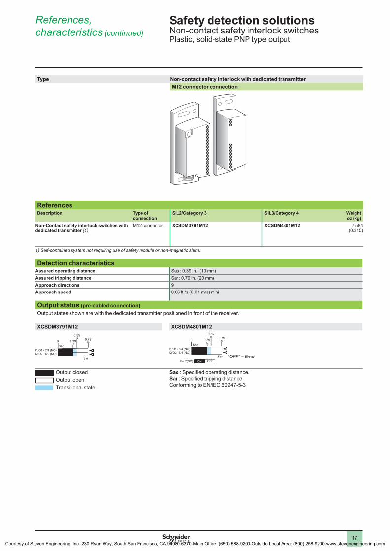
Type Non-contact safety interlock with dedicated transmitter M12 connector connection
ReferencesDescription Type of
connectionSIL2/Category 3 SIL3/Category 4 Weight
oz (kg)Non-Contact safety interlock switches with dedicated transmitter (1)
M12 connector XCSDM3791M12 XCSDM4801M12 7.584 (0.215)
1) Self-contained system not requiring use of safety module or non-magnetic shim.
Detection characteristicsAssured operating distance Sao : 0.39 in. (10 mm)Assured tripping distance Sar : 0.79 in. (20 mm)Approach directions 9Approach speed 0.03 ft./s (0.01 m/s) mini
Output status (pre-cabled connection)Output states shown are with the dedicated transmitter positioned in front of the receiver.
XCSDM3791M12 XCSDM4801M12
Sao
Sar
I1/O1 - 7/4 (NO)I2/O2 - 6/2 (NO)
0 0.3910
0.5514 0.79
20
Sao
Sar
0 0.3910
0.5514 0.79
20
I1/O1 - 5/4 (NO)I2/O2 - 6/4 (NO)
Er- 7(NC) ON OFF
“OFF” = Error
Output closed Sao : Specified operating distance.Sar : Specified tripping distance.Conforming to EN/IEC 60947-5-3
Output openTransitional state
Courtesy of Steven Engineering, Inc.-230 Ryan Way, South San Francisco, CA 94080-6370-Main Office: (650) 588-9200-Outside Local Area: (800) 258-9200-www.stevenengineering.com
18
1
2
4
5
6
7
8
9
10
2
1
4
5
6
7
8
9
10
18
References, characteristics (continued)
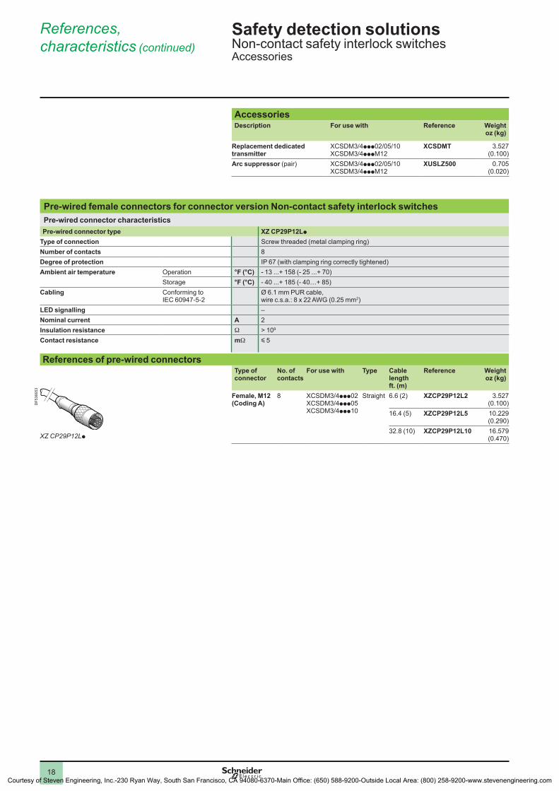
Safety detection solutionsNon-contact safety interlock switchesAccessories
AccessoriesDescription For use with Reference Weight
oz (kg)
Replacement dedicated transmitter
XCSDM3/4ppp02/05/10XCSDM3/4pppM12
XCSDMT 3.527 (0.100)
Arc suppressor (pair) XCSDM3/4ppp02/05/10XCSDM3/4pppM12
XUSLZ500 0.705 (0.020)
Pre-wired female connectors for connector version Non-contact safety interlock switchesPre-wired connector characteristicsPre-wired connector type XZ CP29P12Lp
Type of connection Screw threaded (metal clamping ring)Number of contacts 8Degree of protection IP 67 (with clamping ring correctly tightened)Ambient air temperature Operation °F (°C) - 13 ...+ 158 (- 25 ...+ 70)
Storage °F (°C) - 40 ...+ 185 (- 40…+ 85)Cabling Conforming to
IEC 60947-5-2Ø 6.1 mm PUR cable, wire c.s.a.: 8 x 22 AWG (0.25 mm2)
LED signalling –Nominal current A 2 Insulation resistance W > 109
Contact resistance mW y 5
References of pre-wired connectorsType of connector
No. of contacts
For use with Type Cable length ft. (m)
Reference Weightoz (kg)
Female, M12 (Coding A)
8 XCSDM3/4ppp02XCSDM3/4ppp05XCSDM3/4ppp10
Straight 6.6 (2) XZCP29P12L2 3.527 (0.100)
16.4 (5) XZCP29P12L5 10.229 (0.290)
32.8 (10) XZCP29P12L10 16.579 (0.470)XZ CP29P12Lp
DF5
3665
3
Courtesy of Steven Engineering, Inc.-230 Ryan Way, South San Francisco, CA 94080-6370-Main Office: (650) 588-9200-Outside Local Area: (800) 258-9200-www.stevenengineering.com
19
1
2
4
5
6
7
8
9
10
2
1
4
5
6
7
8
9
10
19
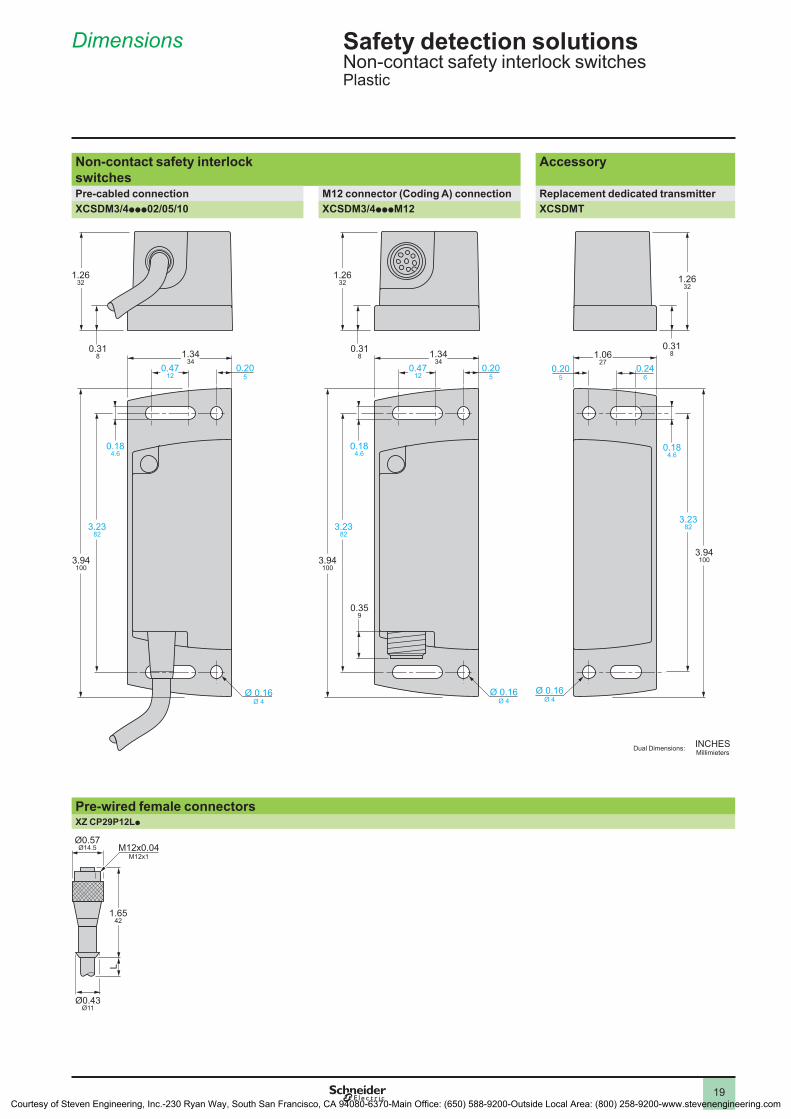
Dimensions
Safety detection solutionsNon-contact safety interlock switchesPlastic
Non-contact safety interlock switches
Accessory
Pre-cabled connection M12 connector (Coding A) connection Replacement dedicated transmitterXCSDM3/4ppp02/05/10 XCSDM3/4pppM12 XCSDMT
0.205
0.184.6
0.318
Ø 0.16Ø 4
1.2632
3.2382
3.94100
0.4712
1.3434
0.359
0.4712
1.3434
0.205
0.318
1.2632
0.184.6
3.2382
3.94100
Ø 0.16Ø 4
0.246
0.205
0.184.6
0.318
Ø 0.16Ø 4
1.2632
1.0627
3.2382
3.94100
Pre-wired female connectorsXZ CP29P12Lp
Ø0.43Ø11
L
M12x0.04M12x1
Ø0.57Ø14.5
1.6542
INCHESMillimietersDual Dimensions:
Courtesy of Steven Engineering, Inc.-230 Ryan Way, South San Francisco, CA 94080-6370-Main Office: (650) 588-9200-Outside Local Area: (800) 258-9200-www.stevenengineering.com
20
1
2
4
5
6
7
8
9
10
2
1
4
5
6
7
8
9
10
20
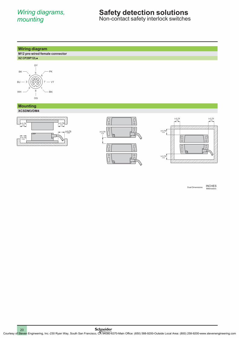
Wiring diagramM12 pre-wired female connector XZ CP29P12Lp
81
7
65
4
3
2
BN
PK
GY
VT
WH
BK
BU
OG
MountingXCSDM3/DM4
u 0.79u 20
u 0.79u 20
u 0.79u 20
u 0.79u 20
u 0.79u 20
u 0.79u 20
u 0.79u 20
u 0.79u 20
u 0.79u 20
Wiring diagrams, mounting
Safety detection solutionsNon-contact safety interlock switches
INCHESMillimietersDual Dimensions:
Courtesy of Steven Engineering, Inc.-230 Ryan Way, South San Francisco, CA 94080-6370-Main Office: (650) 588-9200-Outside Local Area: (800) 258-9200-www.stevenengineering.com
21
1
2
4
5
6
7
8
9
10
2
1
4
5
6
7
8
9
10
21
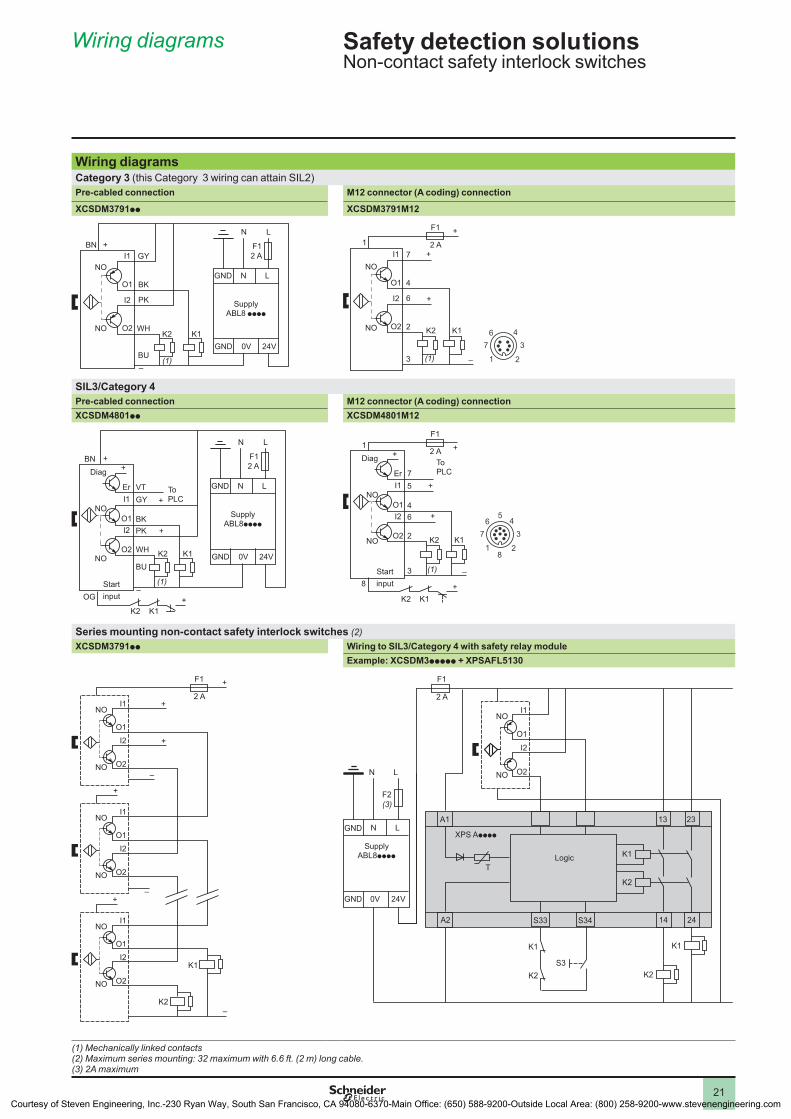
Wiring diagrams
Safety detection solu tionsNon-contact safety interlock switches
Wiring diagramsCategory 3 (this Category 3 wiring can attain SIL2)Pre-cabled connection M12 connector (A coding) connection
XCSDM3791pp XCSDM3791M12
BN
NO
NO
I1
I2
O1
O2
GY
BK
PK
WH
BU
K1K2
(1)
GND
GND
N L
0V 24V
F12 A
+
–
N L
SupplyABL8 pppp
1
NO
NO
I1
I2
O1
O2
7
4
6
2
3
K1K2
+
+
+
– 1
7
6 4
3
2
F1
2 A
(1)
SIL3/Category 4Pre-cabled connection M12 connector (A coding) connectionXCSDM4801pp XCSDM4801M12
BN
NO
NO
I1
I2
O1
O2
VTEr
GY
BK
PK
WH
BU
K1K2
K1K2
+
+
+
OG
+Diag
GND
GND
N L
0V 24V
F12 A
N L
+
(1)–
ToPLC
SupplyABL8pppp
Startinput
1
NO
NO
I1
I2
O1
O2
7Er
5
4
6
2
3
K1K2
K1K2
+
+
+
–
8
+Diag
1
7
6 45
3
28
+
F1
2 A
(1)
ToPLC
Startinput
Series mounting non-contact safety interlock switches (2)XCSDM3791pp Wiring to SIL3/Category 4 with safety relay module
Example: XCSDM3ppppp + XPSAFL5130
I1
O1
I2
NO
NO
O2
I1
O1
I2
NO O2
NO
+
K2
I1
O1
I2
NO O2
NO
K1
+
+
+
+
–
–
–
F1
2 A
A1 13
K1
K2
K2
K1
A2 14
23
24
XPS Apppp
T
S33 S34
K1
K2
S3
I1
O1
I2
NO O2
NO
N L
GND 0V 24V
GND N L
F2(3)
F1
2 A
SupplyABL8pppp Logic
(1) Mechanically linked contacts(2) Maximum series mounting: 32 maximum with 6.6 ft. (2 m) long cable.(3) 2A maximum
Courtesy of Steven Engineering, Inc.-230 Ryan Way, South San Francisco, CA 94080-6370-Main Office: (650) 588-9200-Outside Local Area: (800) 258-9200-www.stevenengineering.com

Schneider Electric www.schneider-electric.com
North American Operating Division1415 South Roselle RoadPalatine, IL 60067USA
TEL: 847-397-2600
ART. 960260 2009
9007
CT0
903
Due to evolution of standards and equipment, the characteristics indicated in texts and images of this document do not constitute a commitment on our part without confirmation.Design: Schneider ElectricPhotos: Schneider Electric
© 2009 Schneider Electric. All rights reserved.
Courtesy of Steven Engineering, Inc.-230 Ryan Way, South San Francisco, CA 94080-6370-Main Office: (650) 588-9200-Outside Local Area: (800) 258-9200-www.stevenengineering.com