Embed Size (px)
Citation preview

Preventa™ Machine Safety ProductsCatalog
20092011 Supplement
Safety Interlock Switches

2 3
2 3
Contents Safety detection solutionsSafety interlock switches
Introduction b .................................................................................................. 4
Specifications b .............................................................................................. 5
Metal, turret head, type XCSLF bReferences, specifications.............................................................................. 6
Plastic, turret head, type XCSLE bReferences, specifications.............................................................................. 8
Actuators, separate components bReferences ..................................................................................................... 9
Pre-wired mini connectors for XCS safety interlocks bReferences ................................................................................................... 10
Dimensions b ................................................................................................. 11
Wiring diagrams b ....................................................................................... 13
4
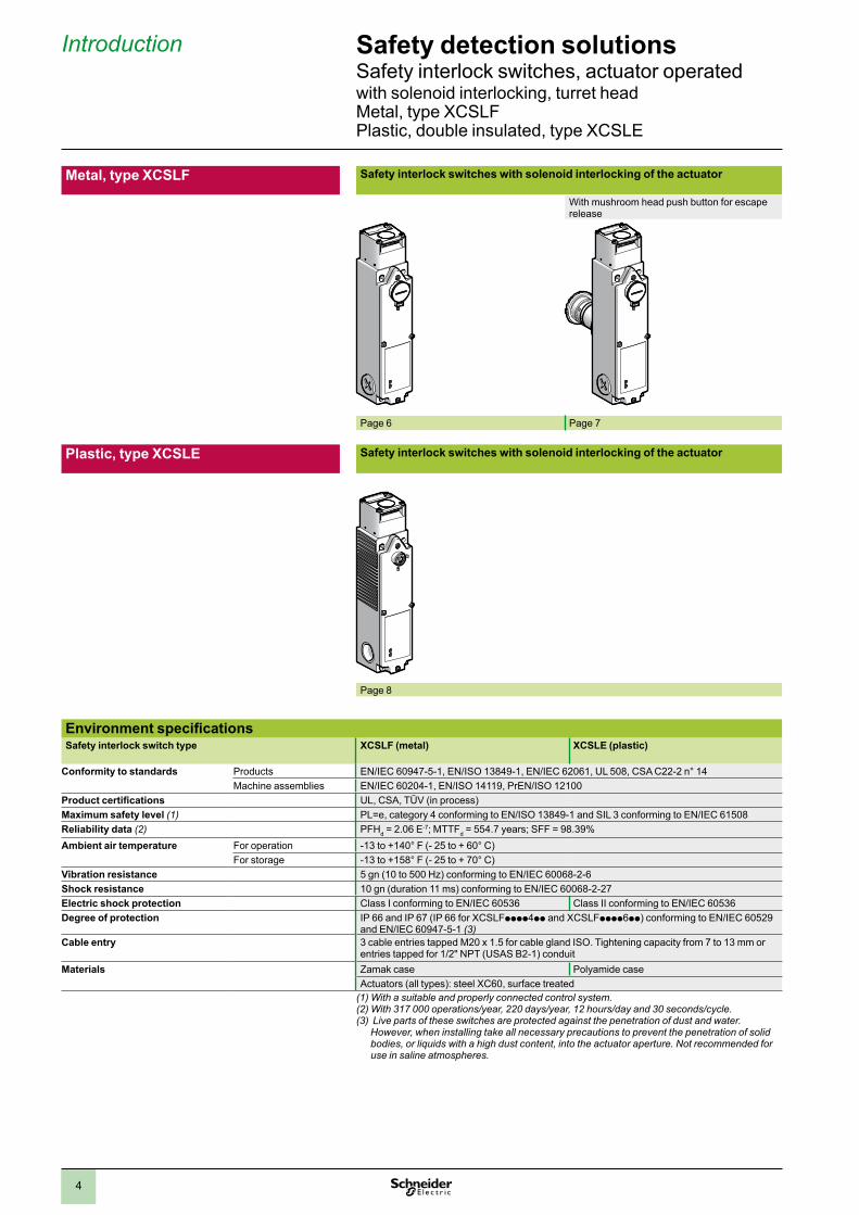
Metal, type XCSLF Safety interlock switches with solenoid interlocking of the actuator
With mushroom head push button for escape release
Page 6 Page 7
Plastic, type XCSLE Safety interlock switches with solenoid interlocking of the actuator
Page 8
Safety detection solutionsSafety interlock switches, actuator operatedwith solenoid interlocking, turret head Metal, type XCSLF Plastic, double insulated, type XCSLE
Introduction
Environment specificationsSafety interlock switch type XCSLF (metal) XCSLE (plastic)
Conformity to standards Products EN/IEC 60947-5-1, EN/ISO 13849-1, EN/IEC 62061, UL 508, CSA C22-2 n° 14Machine assemblies EN/IEC 60204-1, EN/ISO 14119, PrEN/ISO 12100
Product certifications UL, CSA, TÜV (in process)Maximum safety level (1) PL=e, category 4 conforming to EN/ISO 13849-1 and SIL 3 conforming to EN/IEC 61508Reliability data (2) PFHd = 2.06 E-7; MTTFd = 554.7 years; SFF = 98.39% Ambient air temperature For operation -13 to +140° F (- 25 to + 60° C)
For storage -13 to +158° F (- 25 to + 70° C)Vibration resistance 5 gn (10 to 500 Hz) conforming to EN/IEC 60068-2-6Shock resistance 10 gn (duration 11 ms) conforming to EN/IEC 60068-2-27Electric shock protection Class I conforming to EN/IEC 60536 Class II conforming to EN/IEC 60536Degree of protection IP 66 and IP 67 (IP 66 for XCSLFpppp4pp and XCSLFpppp6pp) conforming to EN/IEC 60529
and EN/IEC 60947-5-1 (3)Cable entry 3 cable entries tapped M20 x 1.5 for cable gland ISO. Tightening capacity from 7 to 13 mm or
entries tapped for 1/2" NPT (USAS B2-1) conduitMaterials Zamak case Polyamide case
Actuators (all types): steel XC60, surface treated(1) With a suitable and properly connected control system.(2) With 317 000 operations/year, 220 days/year, 12 hours/day and 30 seconds/cycle.(3) Live parts of these switches are protected against the penetration of dust and water.
However, when installing take all necessary precautions to prevent the penetration of solid bodies, or liquids with a high dust content, into the actuator aperture. Not recommended for use in saline atmospheres.
5
Contact block specificationsRated operational specifications a AC-15, C300: Ue = 240 V, Ie = 0.75 A
c DC-13, R300: Ue = 250 V, Ie = 0.1 A conforming to EN/IEC 60947-5-1
Conventional thermal current in enclosure Ithe = 4 A (max. total thermal current = <15 A)Rated insulation voltage Ui = 250 V degree of pollution 3 conforming to EN/IEC 60947-1
Ui = 300 V conforming to UL 508, CSA C22-2 n° 14
Rated impulse withstand voltage Uimp = 4 kV conforming to EN/IEC 60947-5-1Positive operation N.C. contact(s) with positive opening operation conforming to EN/IEC 60947-5-1, Section 3CMinimum switching current 10 mA at 20 VMinimum switching voltage 17 VShort-circuit protection 4 A cartridge fuse type gG (gl) or 6 A fast actingConnection Spring terminals, capacity:
Minimum: 1 x 20 AWG (0.5 mm2); maximum: 2 x 16 AWG (1.5 mm2); .51” (13 mm) stripped end
Complementary specificationsActuation speed Maximum: 19.7 in/s (0.5 m/s); minimum: 0.39 in/s (0.01 m/s)Resistance to forcible withdrawal of actuator Fzh 2300 N according to the verification principle GS-ET 19 (Fzh=Fmax/1.3)
XCSLF: 517 lbf (2300 N) and with F max = 674.4 lbf (3000 N) XCSLE: 247.2 lbf (1100 N) with F max = 314.7 lbf (1400 N)
Maximum operating rate For maximum life: 600 operating cycles per hourMinimum force for extraction of actuator (not locked) 4.5 lbs (20 N)
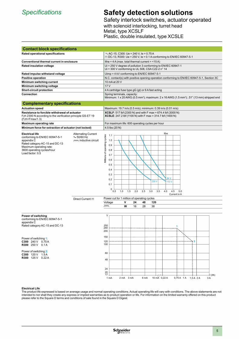
Electrical lifeconforming to EN/IEC 60947-5-1 appendix CRated category AC-15 and DC-13Maximum operating rate: 3600 operating cycles/hourLoad factor: 0.5
Alternating Current a 50/60 Hz o inductive circuit
Direct Current c Power cut for 1 million of operating cyclesVoltage V 24 48 120o W 16 28 38
Power of switchingconforming to EN/IEC 60947-5-1 appendix CRated category AC-15 and DC-13
Power of switching 1: C300 240 V 0.75 AR300 250 V 0.1 A
Power of switching 2: C300 120 V 1.5 AR300 125 V 0.22 A
1 mA 2 mA 3 mA 6 mA 10 mA
20
60
100
17
150
200
1,5 A0,75 A 2 A1 A
120
240
24
V
I (Ith)
48
2
0,22 A
1
3 A
250
Electrical Life The product life expressed is based on average usage and normal operating conditions. Actual operating life will vary with conditions. The above statements are not intended to nor shall they create any express or implied warranties as to product operation or life. For information on the limited warranty offered on this product please refer to the Square D terms and conditions of sale found in the Square D Digest.
Safety detection solutionsSafety interlock switches, actuator operatedwith solenoid interlocking, turret head Metal, type XCSLF Plastic, double insulated, type XCSLE
Specifications
0
0.1
0.2
0.3
0.4
0.5
0.9
1.0
1.1
0.7
0.6
0.8
0.5 1.0 1.5 2.0 2.5 3.0 3.5 4.0 4.5 5.0
230 V 110 V24 V
Ithe
Mill
ions
of o
pera
ting
cycl
es
Current in A
6
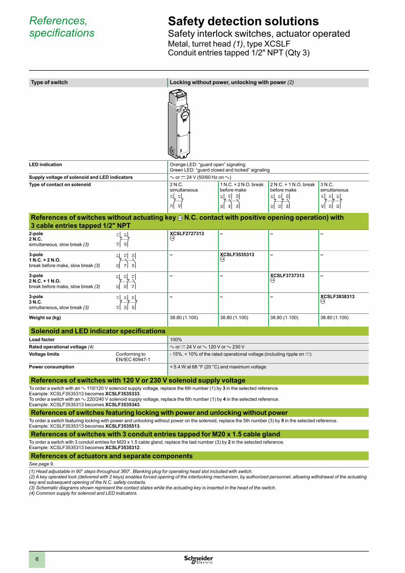
Type of switch Locking without power, unlocking with power (2)
LED indication Orange LED: “guard open” signaling Green LED: “guard closed and locked” signaling
Supply voltage of solenoid and LED indicators a or c 24 V (50/60 Hz on a)Type of contact on solenoid 2 N.C.
simultaneous
3132
4142
1 N.C. + 2 N.O. break before make
535462
61 4344
2 N.C. + 1 N.O. break before make
5251 63
644241
3 N.C.simultaneous
References of switches without actuating key N.C. contact with positive opening operation) with 3 cable entries tapped 1/2" NPT
2-pole 2 N.C. simultaneous, slow break (3)
1112
2122
XCSLF2727313 – – –
3-pole 1 N.C. + 2 N.O. break before make, slow break (3)
333422
21 1314
– XCSLF3535313 – –
3-pole 2 N.C. + 1 N.O. break before make, slow break (3) 32
31 131422
21 – – XCSLF3737313 –
3-pole 3 N.C. simultaneous, slow break (3) 12
11
2221
3231 – – – XCSLF3838313
Weight oz (kg) 38.80 (1.100) 38.80 (1.100) 38.80 (1.100) 38.80 (1.100)
Solenoid and LED indicator specificationsLoad factor 100%Rated operational voltage (4) a or c 24 V or a 120 V or a 230 VVoltage limits Conforming to
EN/IEC 60947-1- 15%, + 10% of the rated operational voltage (including ripple on c)
Power consumption < 5.4 W at 68 °F (20 °C) and maximum voltage
References of switches with 120 V or 230 V solenoid supply voltageTo order a switch with an a 110/120 V solenoid supply voltage, replace the 6th number (1) by 3 in the selected reference. Example: XCSLF3535313 becomes XCSLF3535333.To order a switch with an a 220/240 V solenoid supply voltage, replace the 6th number (1) by 4 in the selected reference. Example: XCSLF3535313 becomes XCSLF3535343.
References of switches featuring locking with power and unlocking without powerTo order a switch featuring locking with power and unlocking without power on the solenoid, replace the 5th number (3) by 5 in the selected reference.Example: XCSLF3535313 becomes XCSLF3535513.
References of switches with 3 conduit entries tapped for M20 x 1.5 cable glandTo order a switch with 3 conduit entries for M20 x 1.5 cable gland, replace the last number (3) by 2 in the selected reference. Example: XCSLF3535313 becomes XCSLF3535312.
References of actuators and separate componentsSee page 9.(1) Head adjustable in 90° steps throughout 360°. Blanking plug for operating head slot included with switch.(2) A key operated lock (delivered with 2 keys) enables forced opening of the interlocking mechanism, by authorized personnel, allowing withdrawal of the actuating key and subsequent opening of the N.C. safety contacts.(3) Schematic diagrams shown represent the contact states while the actuating key is inserted in the head of the switch.(4) Common supply for solenoid and LED indicators.
References, specifications
Safety detection solutionsSafety interlock switches, actuator operatedMetal, turret head (1), type XCSLF Conduit entries tapped 1/2" NPT (Qty 3)
4241
5251
6261
7
References, specifications (continued)
Safety detection solutionsSafety interlock switches, actuator operatedMetal, turret head (1), type XCSLF Conduit entries tapped 1/2" NPT (Qty 3)
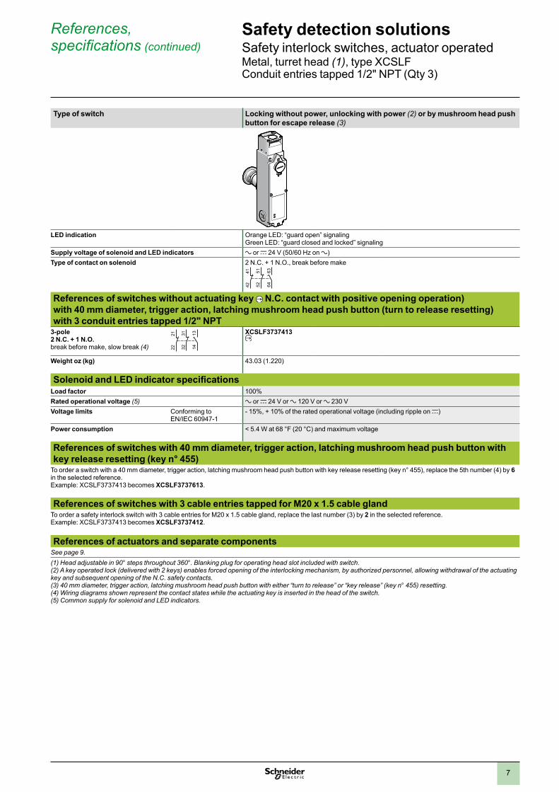
Type of switch Locking without power, unlocking with power (2) or by mushroom head push button for escape release (3)
LED indication Orange LED: “guard open” signaling Green LED: “guard closed and locked” signaling
Supply voltage of solenoid and LED indicators a or c 24 V (50/60 Hz on a)Type of contact on solenoid 2 N.C. + 1 N.O., break before make
References of switches without actuating key N.C. contact with positive opening operation) with 40 mm diameter, trigger action, latching mushroom head push button (turn to release resetting) with 3 conduit entries tapped 1/2" NPT
3-pole 2 N.C. + 1 N.O. break before make, slow break (4) 32
31 131422
21 XCSLF3737413
Weight oz (kg) 43.03 (1.220)
Solenoid and LED indicator specificationsLoad factor 100%Rated operational voltage (5) a or c 24 V or a 120 V or a 230 VVoltage limits Conforming to
EN/IEC 60947-1- 15%, + 10% of the rated operational voltage (including ripple on c)
Power consumption < 5.4 W at 68 °F (20 °C) and maximum voltage
References of switches with 40 mm diameter, trigger action, latching mushroom head push button with key release resetting (key n° 455)
To order a switch with a 40 mm diameter, trigger action, latching mushroom head push button with key release resetting (key n° 455), replace the 5th number (4) by 6 in the selected reference. Example: XCSLF3737413 becomes XCSLF3737613.
References of switches with 3 cable entries tapped for M20 x 1.5 cable glandTo order a safety interlock switch with 3 cable entries for M20 x 1.5 cable gland, replace the last number (3) by 2 in the selected reference. Example: XCSLF3737413 becomes XCSLF3737412.
References of actuators and separate componentsSee page 9.(1) Head adjustable in 90° steps throughout 360°. Blanking plug for operating head slot included with switch.(2) A key operated lock (delivered with 2 keys) enables forced opening of the interlocking mechanism, by authorized personnel, allowing withdrawal of the actuating key and subsequent opening of the N.C. safety contacts.(3) 40 mm diameter, trigger action, latching mushroom head push button with either “turn to release” or “key release” (key n° 455) resetting.(4) Wiring diagrams shown represent the contact states while the actuating key is inserted in the head of the switch.(5) Common supply for solenoid and LED indicators.
5251 63
644241
8
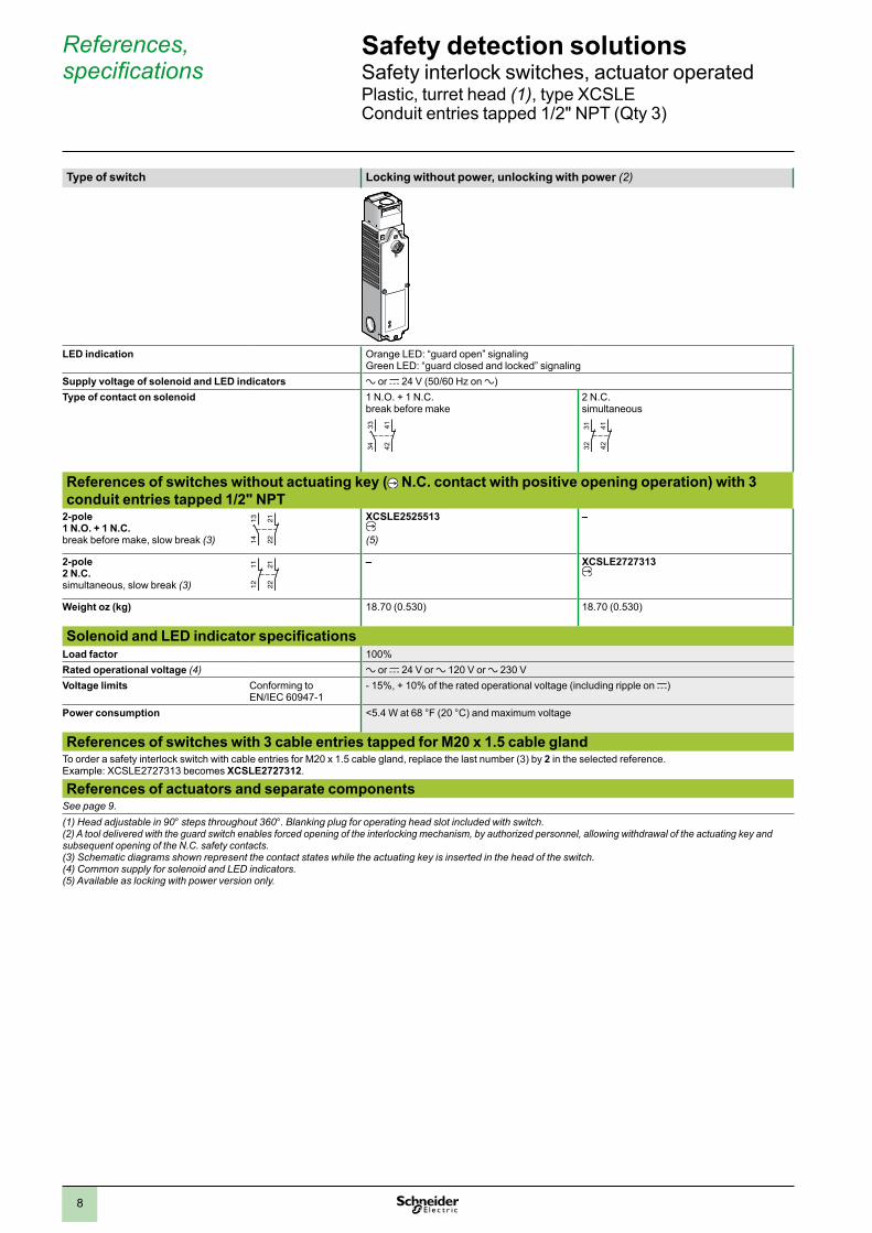
Type of switch Locking without power, unlocking with power (2)
LED indication Orange LED: “guard open” signaling Green LED: “guard closed and locked” signaling
Supply voltage of solenoid and LED indicators a or c 24 V (50/60 Hz on a)Type of contact on solenoid 1 N.O. + 1 N.C.
break before make2 N.C.simultaneous
References of switches without actuating key ( N.C. contact with positive opening operation) with 3 conduit entries tapped 1/2" NPT
2-pole 1 N.O. + 1 N.C. break before make, slow break (3) 22
211314
XCSLE2525513
(5)
–
2-pole 2 N.C. simultaneous, slow break (3)
1112
2122
– XCSLE2727313
Weight oz (kg) 18.70 (0.530) 18.70 (0.530)
Solenoid and LED indicator specificationsLoad factor 100%Rated operational voltage (4) a or c 24 V or a 120 V or a 230 VVoltage limits Conforming to
EN/IEC 60947-1- 15%, + 10% of the rated operational voltage (including ripple on c)
Power consumption <5.4 W at 68 °F (20 °C) and maximum voltage
References of switches with 3 cable entries tapped for M20 x 1.5 cable glandTo order a safety interlock switch with cable entries for M20 x 1.5 cable gland, replace the last number (3) by 2 in the selected reference. Example: XCSLE2727313 becomes XCSLE2727312.
References of actuators and separate componentsSee page 9.(1) Head adjustable in 90° steps throughout 360°. Blanking plug for operating head slot included with switch.(2) A tool delivered with the guard switch enables forced opening of the interlocking mechanism, by authorized personnel, allowing withdrawal of the actuating key and subsequent opening of the N.C. safety contacts.(3) Schematic diagrams shown represent the contact states while the actuating key is inserted in the head of the switch.(4) Common supply for solenoid and LED indicators.(5) Available as locking with power version only.
References, specifications
Safety detection solutionsSafety interlock switches, actuator operatedPlastic, turret head (1), type XCSLE Conduit entries tapped 1/2" NPT (Qty 3)
424133
34
3132
4142
9
References Safety detection solutionsSafety interlock switches, actuator operatedwith solenoid interlocking, turret head Metal, type XCSLF Plastic, double insulated, type XCSLE
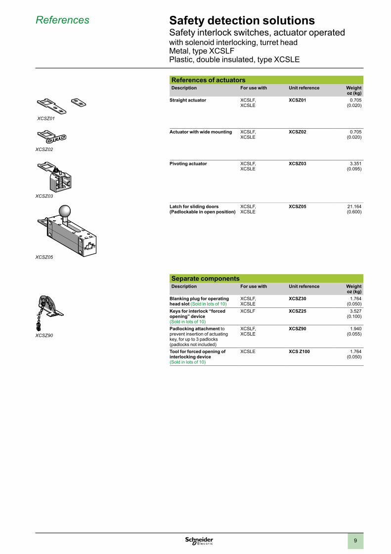
References of actuatorsDescription For use with Unit reference Weight
oz (kg)Straight actuator
XCSLF, XCSLE
XCSZ01 0.705 (0.020)
Actuator with wide mounting
XCSLF, XCSLE
XCSZ02 0.705 (0.020)
Pivoting actuator XCSLF, XCSLE
XCSZ03 3.351 (0.095)
XCSZ05-pers 25%
Latch for sliding doors (Padlockable in open position)
XCSLF, XCSLE
XCSZ05 21.164 (0.600)
Separate componentsDescription For use with Unit reference Weight
oz (kg)Blanking plug for operating head slot (Sold in lots of 10)
XCSLF, XCSLE
XCSZ30 1.764 (0.050)
Keys for interlock “forced opening” device (Sold in lots of 10)
XCSLF XCSZ25 3.527 (0.100)
Padlocking attachment to prevent insertion of actuating key, for up to 3 padlocks (padlocks not included)
XCSLF, XCSLE
XCSZ90 1.940 (0.055)
Tool for forced opening of interlocking device (Sold in lots of 10)
XCSLE XCS Z100 1.764 (0.050)
XCSZ01
XCSZ02
XCSZ03
XCSZ05
XCSZ90
10
1
2 3
1-Green2-Black3-White
1 5
2 43
1-White2-Red3-Green4-Orange5-Black
1 - Orange2 - Blue3 - Red-Blk. Tr.4 - Green-Blk. Tr.5 - White6 - Red7 - Green8 - White-Blk. Tr.9 - Black
17
8 92 5
6
3 4
1-White-Blk. Tr.2-Black3-White4-Red5-Orange6-Blue7-Green
1
2 7 5
6
3 4
1 5
2 43
1-Orange2-Blue3-Black4-White5-Red6-Green
6
References Safety detection solutionsSafety interlock switches, actuator operatedwith solenoid interlocking, turret head Metal, type XCSLF Plastic, double insulated, type XCSLE
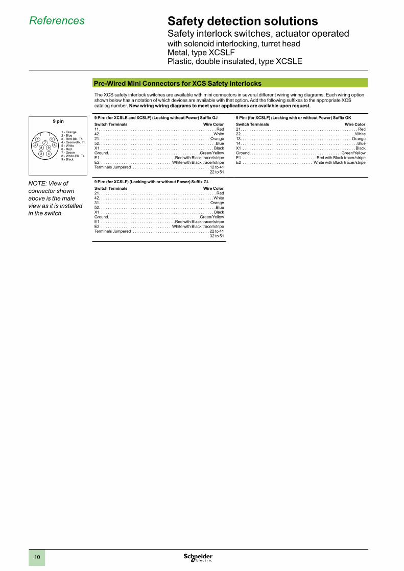
Pre-Wired Mini Connectors for XCS Safety InterlocksThe XCS safety interlock switches are available with mini connectors in several different wiring wiring diagrams. Each wiring option shown below has a notation of which devices are available with that option. Add the following suffixes to the appropriate XCS catalog number. New wiring wiring diagrams to meet your applications are available upon request.
9 Pin: (for XCSLE and XCSLF) (Locking without Power) Suffix GJSwitch Terminals Wire Color11 . . . . . . . . . . . . . . . . . . . . . . . . . . . . . . . . . . . . . . . . . . . . . . . . . . . . Red42. . . . . . . . . . . . . . . . . . . . . . . . . . . . . . . . . . . . . . . . . . . . . . . . . . .White21. . . . . . . . . . . . . . . . . . . . . . . . . . . . . . . . . . . . . . . . . . . . . . . . . Orange52. . . . . . . . . . . . . . . . . . . . . . . . . . . . . . . . . . . . . . . . . . . . . . . . . . . .BlueX1 . . . . . . . . . . . . . . . . . . . . . . . . . . . . . . . . . . . . . . . . . . . . . . . . . . BlackGround. . . . . . . . . . . . . . . . . . . . . . . . . . . . . . . . . . . . . . . . .Green/YellowE1 . . . . . . . . . . . . . . . . . . . . . . . . . . . . . . . . .Red with Black tracer/stripeE2 . . . . . . . . . . . . . . . . . . . . . . . . . . . . . . . White with Black tracer/stripeTerminals Jumpered . . . . . . . . . . . . . . . . . . . . . . . . . . . . . . . . . . 12 to 41
22 to 51
9 Pin: (for XCSLF) (Locking with or without Power) Suffix GKSwitch Terminals Wire Color21. . . . . . . . . . . . . . . . . . . . . . . . . . . . . . . . . . . . . . . . . . . . . . . . . . . . Red22. . . . . . . . . . . . . . . . . . . . . . . . . . . . . . . . . . . . . . . . . . . . . . . . . . .White13. . . . . . . . . . . . . . . . . . . . . . . . . . . . . . . . . . . . . . . . . . . . . . . . . Orange14. . . . . . . . . . . . . . . . . . . . . . . . . . . . . . . . . . . . . . . . . . . . . . . . . . . .BlueX1 . . . . . . . . . . . . . . . . . . . . . . . . . . . . . . . . . . . . . . . . . . . . . . . . . . BlackGround. . . . . . . . . . . . . . . . . . . . . . . . . . . . . . . . . . . . . . . . .Green/YellowE1 . . . . . . . . . . . . . . . . . . . . . . . . . . . . . . . . .Red with Black tracer/stripeE2 . . . . . . . . . . . . . . . . . . . . . . . . . . . . . . . White with Black tracer/stripe
9 Pin: (for XCSLF) (Locking with or without Power) Suffix GLSwitch Terminals Wire Color21. . . . . . . . . . . . . . . . . . . . . . . . . . . . . . . . . . . . . . . . . . . . . . . . . . . . Red42. . . . . . . . . . . . . . . . . . . . . . . . . . . . . . . . . . . . . . . . . . . . . . . . . . .White31. . . . . . . . . . . . . . . . . . . . . . . . . . . . . . . . . . . . . . . . . . . . . . . . . Orange52. . . . . . . . . . . . . . . . . . . . . . . . . . . . . . . . . . . . . . . . . . . . . . . . . . . .BlueX1 . . . . . . . . . . . . . . . . . . . . . . . . . . . . . . . . . . . . . . . . . . . . . . . . . . BlackGround. . . . . . . . . . . . . . . . . . . . . . . . . . . . . . . . . . . . . . . . .Green/YellowE1 . . . . . . . . . . . . . . . . . . . . . . . . . . . . . . . . .Red with Black tracer/stripeE2 . . . . . . . . . . . . . . . . . . . . . . . . . . . . . . . White with Black tracer/stripeTerminals Jumpered . . . . . . . . . . . . . . . . . . . . . . . . . . . . . . . . . . 22 to 41
32 to 51
9 pin
NOTE: View of connector shown above is the male view as it is installed in the switch.
11
Safety detection solutionsSafety interlock switches, actuator operatedwith solenoid interlocking, turret head Metal, type XCSLF Plastic, double insulated, type XCSLE
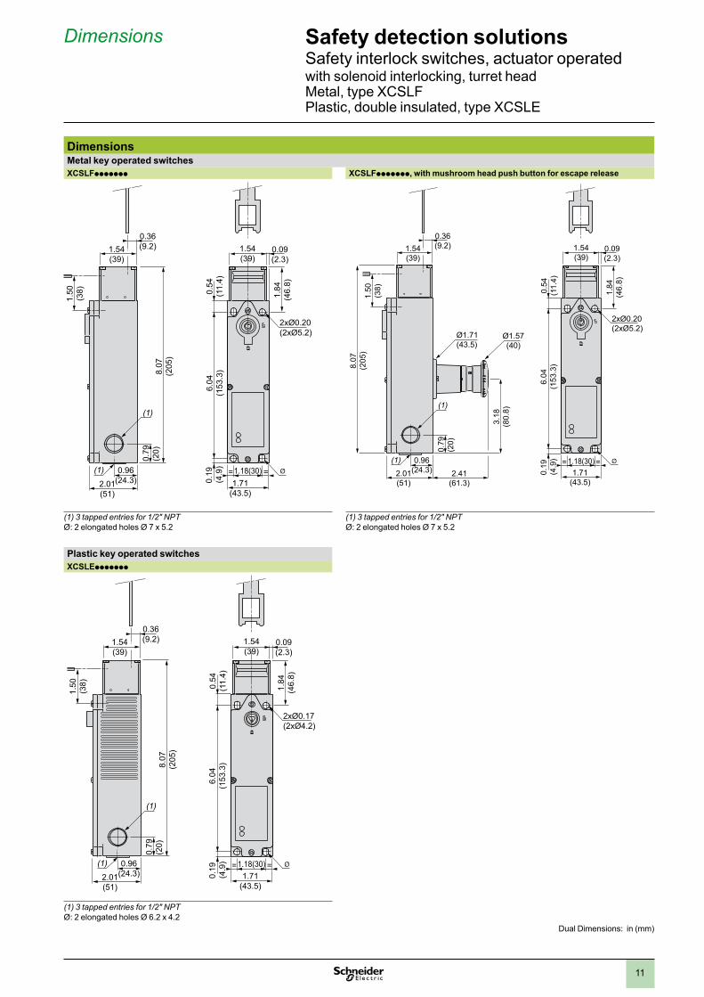
DimensionsMetal key operated switchesXCSLFppppppp XCSLFppppppp, with mushroom head push button for escape release
2xØ0.20(2xØ5.2)
1.71(43.5)
1.18(30)= =
6.04
(153
.3)
0.54
(11.
4)0.
19(4
.9)
1.84
(46.
8)
1.54(39)
0.09(2.3)
0.36(9.2)
1.50
(38)
8.07
(205
)
1.54(39)
0.79
(20)
(1)
0.96(24.3)
(1)
2.01(51)
0.36(9.2)
1.50
(38)
8.07
(205
)
1.54(39)
0.79
(20)
(1)
0.96(24.3)
(1)
2.01(51)
2.41(61.3)
1.71(43.5)
1.18(30)= =
6.04
(153
.3)
0.54
(11.
4)0.
19(4
.9)
3.18
(80.
8)
Ø1.71(43.5)
Ø1.57(40)
2xØ0.20(2xØ5.2)
1.84
(46.
8)
1.54(39)
0.09(2.3)
(1) 3 tapped entries for 1/2" NPTØ: 2 elongated holes Ø 7 x 5.2
(1) 3 tapped entries for 1/2" NPTØ: 2 elongated holes Ø 7 x 5.2
Plastic key operated switchesXCSLEppppppp
8.07
(205
)
(1)
(1)
2xØ0.17(2xØ4.2)
= =
0.36(9.2)
1.50
(38)
1.54(39)
0.79
(20)
0.96(24.3)2.01
(51)1.71
(43.5)
1.18(30)
6.04
(153
.3)
0.54
(11.
4)0.
19(4
.9)
1.84
(46.
8)
1.54(39)
0.09(2.3)
(1) 3 tapped entries for 1/2" NPTØ: 2 elongated holes Ø 6.2 x 4.2
Dimensions
Dual Dimensions: in (mm)
12
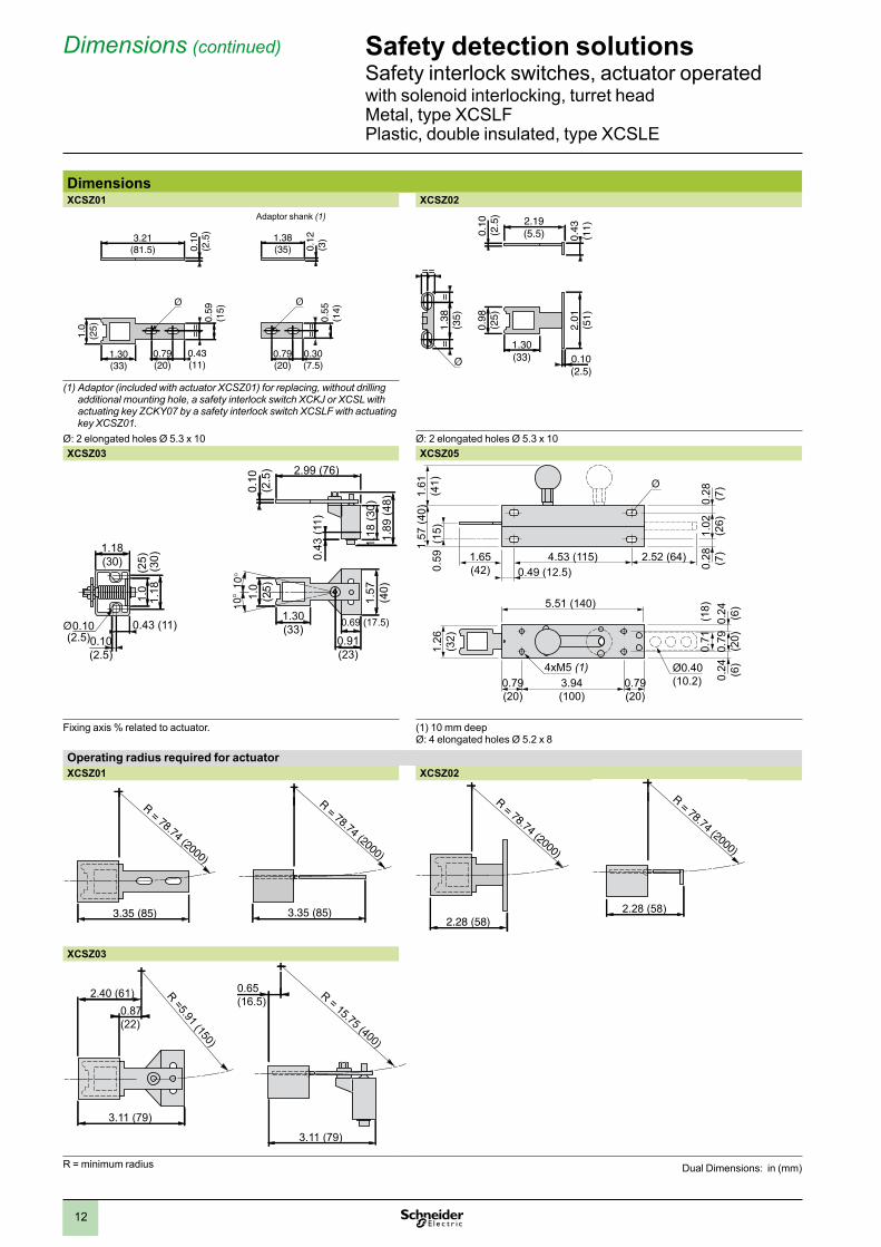
DimensionsXCSZ01 XCSZ02
(1) Adaptor (included with actuator XCSZ01) for replacing, without drilling additional mounting hole, a safety interlock switch XCKJ or XCSL with actuating key ZCKY07 by a safety interlock switch XCSLF with actuating key XCSZ01.
Ø: 2 elongated holes Ø 5.3 x 10 Ø: 2 elongated holes Ø 5.3 x 10XCSZ03 XCSZ05
1.89
(48)
2.99 (76)
0.10
(2.5
)
0.43
(11)
1.57
(40)
0.69 (17.5)
0.91(23)
1.30(33)
1.0
(25)
1.18
(30)
1.18(30)
0.10(2.5)
0.43 (11)
1.18
(3
0)1.
0
(25)
0.10(2.5)
1.57
(40)
0.59
(15
)1.
61(4
1)1.
26(3
2)
5.51 (140)
3.94(100)
0.79(20)
0.79(20)
4xM5 (1)
1.02
(26)
0.28 (7)
0.28 (7)1.65
(42) 0.49 (12.5)4.53 (115) 2.52 (64)
0.79
(20)
0.24 (6)
0.24 (6)
0.71
(1
8)
Ø0.40(10.2)
Fixing axis % related to actuator. (1) 10 mm deepØ: 4 elongated holes Ø 5.2 x 8
Operating radius required for actuatorXCSZ01 XCSZ02
XCSZ03
R = minimum radius
0.12
(3)
==
0.55
(14)
1.38(35)
0.79(20)
0.30(7.5)
0.10
(2.5
)=
=0.
59(1
5)
1.0
(25)
3.21(81.5)
1.30(33)
0.79(20)
0.43(11)
Adaptor shank (1)
R = 78.74 (2000)
3.35 (85)
R = 78.74 (2000)
3.35 (85)
Safety detection solutionsSafety interlock switches, actuator operatedwith solenoid interlocking, turret head Metal, type XCSLF Plastic, double insulated, type XCSLE
Dimensions (continued)
R = 78.74 (2000)
2.28 (58)
R = 78.74 (2000)
2.28 (58)
R =5.91 (150)
0.87(22)
2.40 (61)
3.11 (79)
R = 15.75 (400)
0.65(16.5)
3.11 (79)
0.43
(11)2.19
(5.5)0.10
(2.5
)
2.01
(51)
1.38
(35)
=
==
=
0.98
(25)
1.30(33) 0.10
(2.5)
Dual Dimensions: in (mm)
13
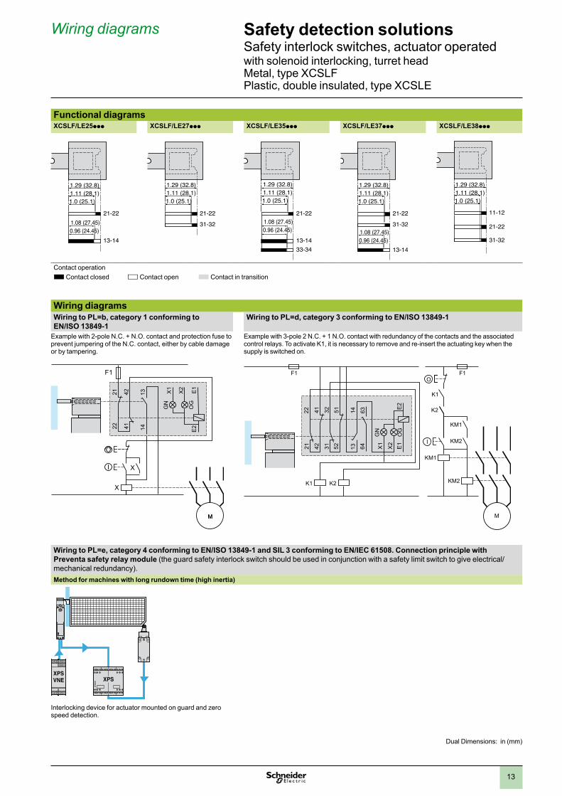
Functional diagramsXCSLF/LE25ppp XCSLF/LE27ppp XCSLF/LE35ppp XCSLF/LE37ppp XCSLF/LE38ppp
21-22
31-32
13-14
1.0 (25.1)
0.96 (24.45)1.08 (27.45)
1.11 (28.1)1.29 (32.8)
11-12
21-22
31-32
1.0 (25.1)1.11 (28.1)1.29 (32.8)
Contact operationG Contact closed H Contact open G Contact in transition
Wiring diagramsWiring to PL=b, category 1 conforming to EN/ISO 13849-1
Wiring to PL=d, category 3 conforming to EN/ISO 13849-1
Example with 2-pole N.C. + N.O. contact and protection fuse to prevent jumpering of the N.C. contact, either by cable damage or by tampering.
Example with 3-pole 2 N.C. + 1 N.O. contact with redundancy of the contacts and the associated control relays. To activate K1, it is necessary to remove and re-insert the actuating key when the supply is switched on.
Wiring to PL=e, category 4 conforming to EN/ISO 13849-1 and SIL 3 conforming to EN/IEC 61508. Connection principle with Preventa safety relay module (the guard safety interlock switch should be used in conjunction with a safety limit switch to give electrical/mechanical redundancy).Method for machines with long rundown time (high inertia)
XPSXPSVNE XPSXPSVNE
Interlocking device for actuator mounted on guard and zero speed detection.
1.0 (25.1)
0.96 (24.45)1.08 (27.45)
1.11 (28.1)1.29 (32.8)
21-22
13-14
21-22
31-32
1.0 (25.1)1.11 (28.1)1.29 (32.8)
21-22
13-1433-34
1.0 (25.1)
0.96 (24.45)1.08 (27.45)
1.11 (28.1)1.29 (32.8)
F1
X
O
I
X
MM
13
2221
41 14
42 X1
X2
E2
E1
GN
OG
KM1
I
KM2
K2
K1
KM1
KM2
M
2221
1413 64
63
523132
4241 51
F1 F1
K1 K2
OX
1
X2
E2
E1
GN
OG
Safety detection solutionsSafety interlock switches, actuator operatedwith solenoid interlocking, turret head Metal, type XCSLF Plastic, double insulated, type XCSLE
Wiring diagrams
Dual Dimensions: in (mm)
14
F1
14
2221
42
13
41
3231
52 51
X1
X2
E2E1
GN
OG
KM1
S1
KM2
X
F1
14
2221
42
13
41
3231
52 51
X1
X2
E2E1
SGN
OG
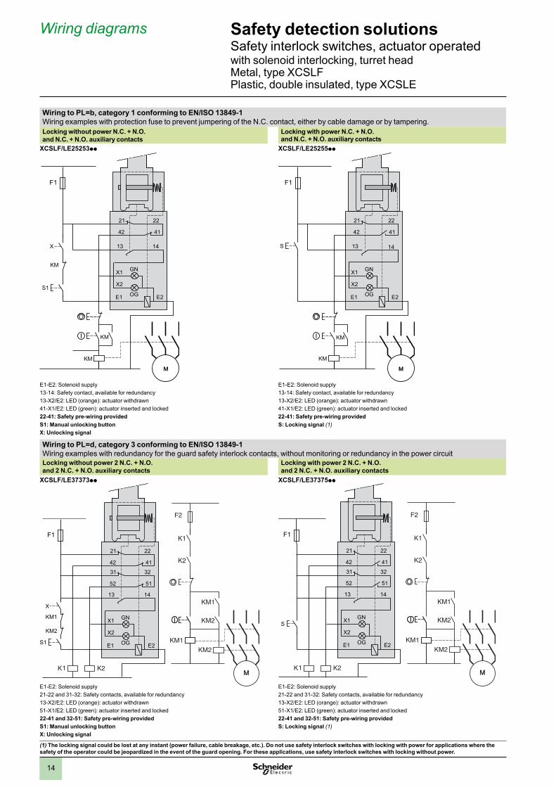
Wiring to PL=b, category 1 conforming to EN/ISO 13849-1Wiring examples with protection fuse to prevent jumpering of the N.C. contact, either by cable damage or by tampering.Locking without power N.C. + N.O.and N.C. + N.O. auxiliary contacts
Locking with power N.C. + N.O.and N.C. + N.O. auxiliary contacts
XCSLF/LE25253pp XCSLF/LE25255pp
E1-E2: Solenoid supply E1-E2: Solenoid supply13-14: Safety contact, available for redundancy 13-14: Safety contact, available for redundancy13-X2/E2: LED (orange): actuator withdrawn 13-X2/E2: LED (orange): actuator withdrawn41-X1/E2: LED (green): actuator inserted and locked 41-X1/E2: LED (green): actuator inserted and locked22-41: Safety pre-wiring provided 22-41: Safety pre-wiring providedS1: Manual unlocking button S: Locking signal (1)X: Unlocking signal
Wiring to PL=d, category 3 conforming to EN/ISO 13849-1Wiring examples with redundancy for the guard safety interlock contacts, without monitoring or redundancy in the power circuitLocking without power 2 N.C. + N.O. and 2 N.C. + N.O. auxiliary contacts
Locking with power 2 N.C. + N.O. and 2 N.C. + N.O. auxiliary contacts
XCSLF/LE37373pp XCSLF/LE37375pp
E1-E2: Solenoid supply E1-E2: Solenoid supply21-22 and 31-32: Safety contacts, available for redundancy 21-22 and 31-32: Safety contacts, available for redundancy13-X2/E2: LED (orange): actuator withdrawn 13-X2/E2: LED (orange): actuator withdrawn51-X1/E2: LED (green): actuator inserted and locked 51-X1/E2: LED (green): actuator inserted and locked22-41 and 32-51: Safety pre-wiring provided 22-41 and 32-51: Safety pre-wiring providedS1: Manual unlocking button S: Locking signal (1)X: Unlocking signal
(1) The locking signal could be lost at any instant (power failure, cable breakage, etc.). Do not use safety interlock switches with locking with power for applications where the safety of the operator could be jeopardized in the event of the guard opening. For these applications, use safety interlock switches with locking without power.
Safety detection solutionsSafety interlock switches, actuator operatedwith solenoid interlocking, turret head Metal, type XCSLF Plastic, double insulated, type XCSLE
Wiring diagrams
F1
KM
KM
O
I
KM
MM
14
2221
42
13
41
X1
X2
E2E1
S1
X
GN
OG
F1
KM
O
I
KM
MM
14
2221
42
13
41
X1
X2
E2E1
S
GN
OG

15

The information and dimensions in this catalog are provided for the convenience of our customers. While this information is believed to be accurate, Schneider Electric reserves the right to make updates and changes without prior notification and assumes no liability for any errors or omissions.
Preventa, Schneider Electric and logo, and "Make the most of your energy" are trademarks or registered trademarks of Schneider Electric or its affiliates in the United States and other countries. Other trademarks used herein are the property of their respective owners.
Design: Schneider ElectricPhotos: Schneider Electric
© 2011 Schneider Electric. All rights reserved. 06/2011MKTED208051EN-US-2011-SUP
http://www.schneider-electric.us/Schneider Electric USA, Inc.8001 Knightdale Blvd. Knightdale, NC 27545
USA Customer Care CenterTel: 888-778-2733
Schneider Electric Canada5985 McLaughlin Rd.Missassauga, Ontario, Canada L5R 1B8
Canada Customer Care CenterTel: 800-565-6699