Embed Size (px)
Citation preview
<< Prev TUBE CAD JOURNAL Next >>
www.tubecad.com Copyright © 2002 GlassWare All Rights Reserved NEXT > < PREVIOUS 1 Pg.
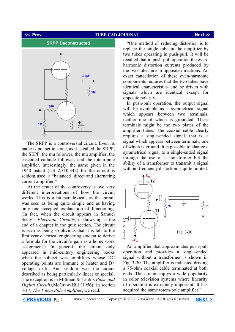
An amplifier that approximates push-pull operation and provides a single-ended signal without a transformer is shown in Fig. 3-30. The amplifier is indicated driving a 75-ohm coaxial cable terminated at both ends. The circuit enjoys a wide popularity in color television systems where linearity of operation is extremely important. It has acquired the name totem-pole amplifier.”
The SRPP is a controversial circuit. Even its name is not set in stone, as it is called the SRPP, the SEPP, the mu follower, the mu amplifier, the cascoded cathode follower, and the totem-pole amplifier. Interestingly, the name given in the 1940 patent (US 2,310,342) for the circuit is seldom used: a “balanced direct and alternating current amplifier.” At the center of the controversy is two very different interpretations of how the circuit works. This is a bit paradoxical, as the circuit was seen as being quite simple and as having only one accepted explanation of functioning. (In fact, when the circuit appears in Samuel Seely’s Electronic Circuits, it shows up at the end of a chapter in the quiz section. The circuit is seen as being so obvious that it is left to the first year electrical engineering student to derive a formula for the circuit’s gain as a home work assignment.) In general, the circuit only appeared in mid-century engineering books when the subject was amplifiers whose DC operating points are immune to heater and B+ voltage drift. And seldom was the circuit described as being particularly linear or special. The exception is in Millman & Taub’s Pulse and Digital Circuits,McGraw-Hill (1956); in section 3-17, The Totem Pole Amplifier, we read:
“One method of reducing distortion is to replace the single tube in the amplifier by two tubes operating in push-pull. It will be recalled that in push-pull operation the even-harmonic distortion currents produced by the two tubes are in opposite directions. An exact cancellation of these even-harmonic components requires that the two tubes have identical characteristics and be driven with signals which are identical except for opposite polarity. In push-pull operation, the output signal will be available as a symmetrical signal which appears between two terminals, neither one of which is grounded. These terminals might be the two plates of the amplifier tubes. The coaxial cable clearly requires a single-ended signal, that is, a signal which appears between terminals, one of which is ground. It is possible to change a symmetrical signal to a single-ended signal through the use of a transformer but the ability of a transformer to transmit a signal without frequency distortion is quite limited.
SRPP Deconstructed
300
1M
1M
.33µF
T1
EbbT2
+ei-
-Ecc
75 75
Fig. 3-30
<< Prev TUBE CAD JOURNAL Next >>
www.tubecad.com Copyright © 2002 GlassWare All Rights Reserved NEXT > < PREVIOUS 2 Pg.
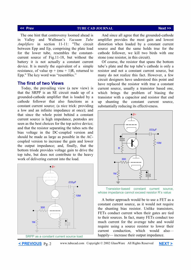
The one hint that controversy loomed ahead is in Valley and Wallman’s Vacuum Tube Amplifiers in section 11-11: "The circuit between Epp and Ep, comprising the plate load for the lower tube, resembles the constant-current source of Fig.11-18, but without the battery it is not actually a constant current device. It is merely the equivalent of a simple resistance, of value rp + (mu + 1)R, returned to Epp." The key word was “resembles.” The first of two Views Today, the prevailing view (a new view) is that the SRPP is an SE circuit made up of a grounded-cathode amplifier that is loaded by a cathode follower that also functions as a constant current source; (a nice trick: providing a low and an infinite impedance at once); and that since the whole point behind a constant current source is high impedance, pentodes are seen as the best choices for the top active device; and that the resistor separating the tubes sets the bias voltage in the DC-coupled version and should be made as large as possible in the AC-coupled version to increase the gain and lower the output impedance; and, finally, that the bottom triode provides voltage gain to drive the top tube, but does not contribute to the heavy work of delivering current into the load.
A better approach would be to use a FET as a constant current source, as it would not require the shunting bias resistor. Unlike transistors, FETs conduct current when their gates are tied to their sources. In fact, many FETs conduct too much current for the average tube and would require using a source resistor to lower their current conduction, which would also—happily— increase their output impedance.
And since all agree that the grounded-cathode amplifier provides the most gain and lowest distortion when loaded by a constant current source and that the same holds true for the cathode follower, we kill two birds with one stone (one resistor, in this circuit). Of course, the resistor that spans the bottom tube’s plate and the top tube’s cathode is only a resistor and not a constant current source, but many do not realize this fact. However, a few circuit designers have understood this point and have replaced the resistor with true a constant current source, usually a transistor based one, which brings the problem of biasing the transistor with a capacitor and resistor that end up shunting the constant current source, substantially reducing its effectiveness.
300
1M
10M
B+
.033µF
SRPP as a constant current source load
300
1M
10M
B+
.033µF
R
Transistor-based constant current source, whose impedance cannot exceed resistor R’s value
<< Prev TUBE CAD JOURNAL Next >>
www.tubecad.com Copyright © 2002 GlassWare All Rights Reserved NEXT > < PREVIOUS 3 Pg.
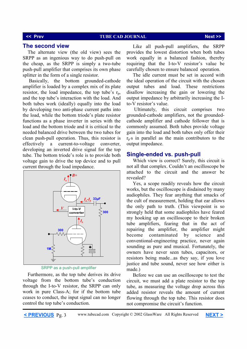
Furthermore, as the top tube derives its drive voltage from the bottom tube’s conduction through the I-to-V resistor, the SRPP can only work in pure Class-A; for if the bottom tube ceases to conduct, the input signal can no longer control the top tube’s conduction.
Like all push-pull amplifiers, the SRPP provides the lowest distortion when both tubes work equally in a balanced fashion, thereby requiring that the I-to-V resistor’s value be carefully chosen to ensure balanced operation. The idle current must be set in accord with the ideal operation of the circuit with the chosen output tubes and load. These restrictions disallow increasing the gain or lowering the output impedance by arbitrarily increasing the I-to-V resistor’s value. Ultimately, this circuit comprises two grounded-cathode amplifiers, not the grounded-cathode amplifier and cathode follower that is commonly assumed. Both tubes provide voltage gain into the load and both tubes only offer their rp’s in parallel as the main contributors to the output impedance. Single-ended vs. push-pull Which view is correct? Surely, this circuit is not all that complex. Couldn’t an oscilloscope be attached to the circuit and the answer be revealed? Yes, a scope readily reveals how the circuit works, but the oscilloscope is disdained by many audiophiles. They fear anything that smacks of the cult of measurement, holding that ear allows the only path to truth. (This viewpoint is so strongly held that some audiophiles have feared my hooking up an oscilloscope to their broken tube amplifiers, fearing that in the act of repairing the amplifier, the amplifier might become contaminated by science and conventional-engineering practice, never again sounding as pure and musical. Fortunately, the owners have never seen tubes, capacitors, or resistors being made...as they say, if you love justice and tube sound, never see how either is made.) Before we can use an oscilloscope to test the circuit, we must add a plate resistor to the top tube, as measuring the voltage drop across this added resistor reveals the amount of current flowing through the top tube. This resistor does not compromise the circuit’s function.
The second view The alternate view (the old view) sees the SRPP as an ingenious way to do push-pull on the cheap, as the SRPP is simply a two-tube push-pull amplifier that comprises its own phase splitter in the form of a single resistor. Basically, the bottom grounded-cathode amplifier is loaded by a complex mix of its plate resistor, the load impedance, the top tube’s rp, and the top tube’s interaction with the load. And both tubes work (ideally) equally into the load by developing two anti-phase current paths into the load, while the bottom triode’s plate resistor functions as a phase inverter in series with the load and the bottom triode and it is critical to the needed balanced drive between the two tubes for clean push-pull operation. Thus, this resistor is effectively a current-to-voltage converter, developing an inverted drive signal for the top tube. The bottom triode’s role is to provide both voltage gain to drive the top device and to pull current through the load impedance.
300
1M
300
B+
33µF
I-to-Vconverter
V
Ib
Ia
Ia-Ib
SRPP as a push-pull amplifier
<< Prev TUBE CAD JOURNAL Next >>
www.tubecad.com Copyright © 2002 GlassWare All Rights Reserved NEXT > < PREVIOUS 4 Pg.
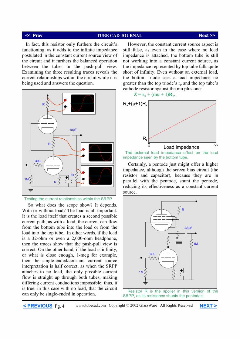
Rk
Ra+(µ+1)Rk
0 ∞Load impedance
Testing the current relationships within the SRPP
In fact, this resistor only furthers the circuit’s functioning, as it adds to the infinite impedance postulated in the constant current source view of the circuit and it furthers the balanced operation between the tubes in the push-pull view. Examining the three resulting traces reveals the current relationships within the circuit while it is being used and answers the question.
300
1M1k
10µF
R
R
R
So what does the scope show? It depends. With or without load? The load is all important. It is the load itself that creates a second possible current path, as with a load, the current can flow from the bottom tube into the load or from the load into the top tube. In other words, if the load is a 32-ohm or even a 2,000-ohm headphone, then the traces show that the push-pull view is correct. On the other hand, if the load is infinity, or what is close enough, 1-meg for example, then the single-ended/constant current source interpretation is half correct, as when the SRPP attaches to no load, the only possible current flow is straight up through both tubes, making differing current conductions impossible; thus, it is true, in this case with no load, that the circuit can only be single-ended in operation.
However, the constant current source aspect is still false, as even in the case where no load impedance is attached, the bottom tube is still not working into a constant current source, as the impedance represented by top tube falls quite short of infinity. Even without an external load, the bottom triode sees a load impedance no greater than the top triode’s rp and the top tube’s cathode resistor against the mu plus one: Z = rp + (mu + 1)Rk.
1M
.33µF
300
1M
R
Resistor R is the spoiler in this version of the SRPP, as its resistance shunts the pentode’s.
Certainly, a pentode just might offer a higher impedance, although the screen bias circuit (the resistor and capacitor), because they are in parallel with the pentode, shunt the pentode, reducing its effectiveness as a constant current source.
The external load impedance effect on the load impedance seen by the bottom tube.
<< Prev TUBE CAD JOURNAL Next >>
www.tubecad.com Copyright © 2002 GlassWare All Rights Reserved NEXT > < PREVIOUS 5 Pg.
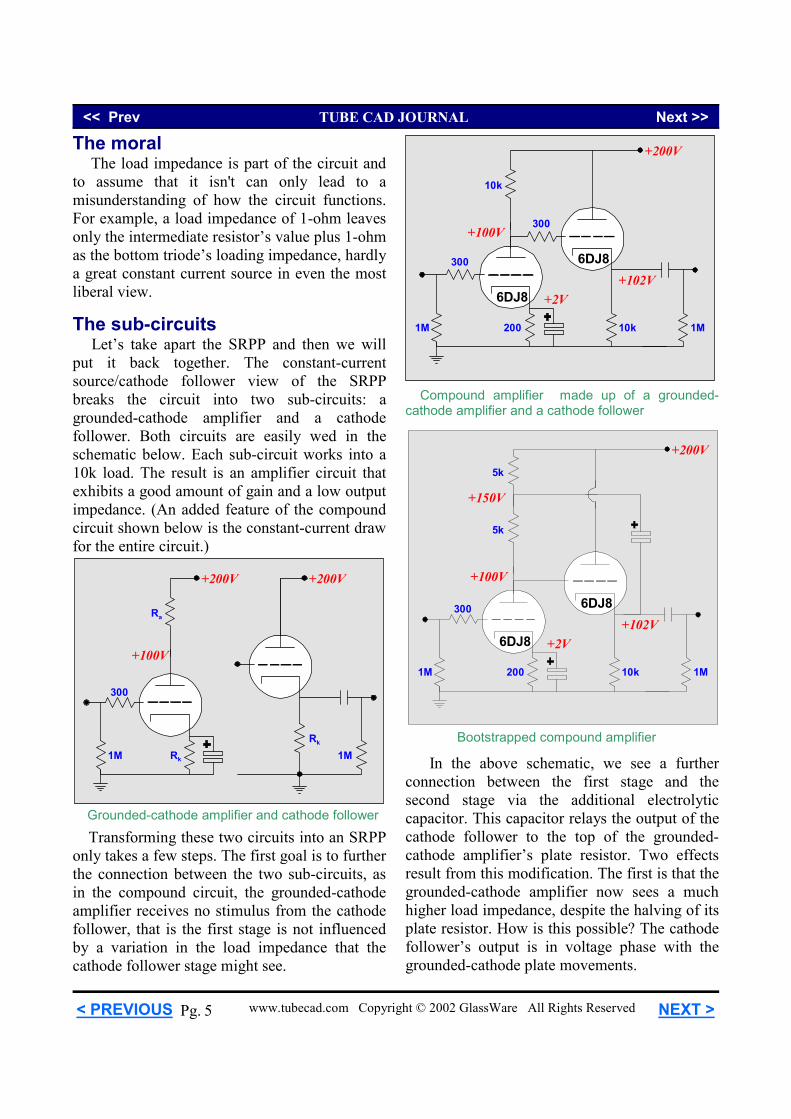
In the above schematic, we see a further connection between the first stage and the second stage via the additional electrolytic capacitor. This capacitor relays the output of the cathode follower to the top of the grounded-cathode amplifier’s plate resistor. Two effects result from this modification. The first is that the grounded-cathode amplifier now sees a much higher load impedance, despite the halving of its plate resistor. How is this possible? The cathode follower’s output is in voltage phase with the grounded-cathode plate movements.
6DJ8
1M
+200V
6DJ8
10k
+100V
+150V
5k
5k
+102V+2V
200 1M
300
Bootstrapped compound amplifier 1M
+200V
+100V
Rk 1M
300
Ra
+200V
Rk
Grounded-cathode amplifier and cathode follower
Transforming these two circuits into an SRPP only takes a few steps. The first goal is to further the connection between the two sub-circuits, as in the compound circuit, the grounded-cathode amplifier receives no stimulus from the cathode follower, that is the first stage is not influenced by a variation in the load impedance that the cathode follower stage might see.
6DJ8
1M
+200V
6DJ8
10k
+100V
+102V+2V
200 1M
300
10k
300
Compound amplifier made up of a grounded-cathode amplifier and a cathode follower
The moral The load impedance is part of the circuit and to assume that it isn't can only lead to a misunderstanding of how the circuit functions. For example, a load impedance of 1-ohm leaves only the intermediate resistor’s value plus 1-ohm as the bottom triode’s loading impedance, hardly a great constant current source in even the most liberal view. The sub-circuits Let’s take apart the SRPP and then we will put it back together. The constant-current source/cathode follower view of the SRPP breaks the circuit into two sub-circuits: a grounded-cathode amplifier and a cathode follower. Both circuits are easily wed in the schematic below. Each sub-circuit works into a 10k load. The result is an amplifier circuit that exhibits a good amount of gain and a low output impedance. (An added feature of the compound circuit shown below is the constant-current draw for the entire circuit.)
<< Prev TUBE CAD JOURNAL Next >>
www.tubecad.com Copyright © 2002 GlassWare All Rights Reserved NEXT > < PREVIOUS 6 Pg.
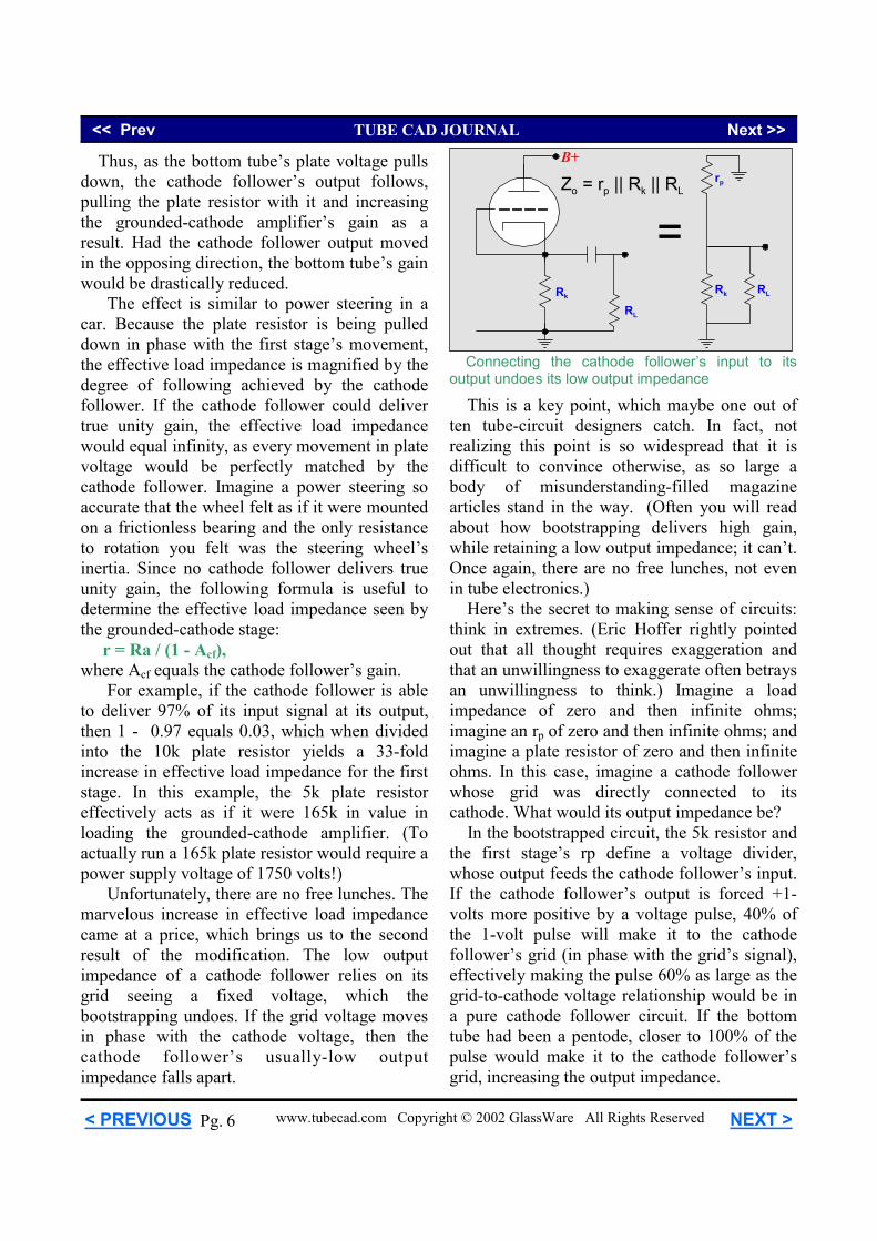
Thus, as the bottom tube’s plate voltage pulls down, the cathode follower’s output follows, pulling the plate resistor with it and increasing the grounded-cathode amplifier’s gain as a result. Had the cathode follower output moved in the opposing direction, the bottom tube’s gain would be drastically reduced. The effect is similar to power steering in a car. Because the plate resistor is being pulled down in phase with the first stage’s movement, the effective load impedance is magnified by the degree of following achieved by the cathode follower. If the cathode follower could deliver true unity gain, the effective load impedance would equal infinity, as every movement in plate voltage would be perfectly matched by the cathode follower. Imagine a power steering so accurate that the wheel felt as if it were mounted on a frictionless bearing and the only resistance to rotation you felt was the steering wheel’s inertia. Since no cathode follower delivers true unity gain, the following formula is useful to determine the effective load impedance seen by the grounded-cathode stage: r = Ra / (1 - Acf), where Acf equals the cathode follower’s gain. For example, if the cathode follower is able to deliver 97% of its input signal at its output, then 1 - 0.97 equals 0.03, which when divided into the 10k plate resistor yields a 33-fold increase in effective load impedance for the first stage. In this example, the 5k plate resistor effectively acts as if it were 165k in value in loading the grounded-cathode amplifier. (To actually run a 165k plate resistor would require a power supply voltage of 1750 volts!) Unfortunately, there are no free lunches. The marvelous increase in effective load impedance came at a price, which brings us to the second result of the modification. The low output impedance of a cathode follower relies on its grid seeing a fixed voltage, which the bootstrapping undoes. If the grid voltage moves in phase with the cathode voltage, then the cathode follower’s usually-low output impedance falls apart.
This is a key point, which maybe one out of ten tube-circuit designers catch. In fact, not realizing this point is so widespread that it is difficult to convince otherwise, as so large a body of misunderstanding-filled magazine articles stand in the way. (Often you will read about how bootstrapping delivers high gain, while retaining a low output impedance; it can’t. Once again, there are no free lunches, not even in tube electronics.) Here’s the secret to making sense of circuits: think in extremes. (Eric Hoffer rightly pointed out that all thought requires exaggeration and that an unwillingness to exaggerate often betrays an unwillingness to think.) Imagine a load impedance of zero and then infinite ohms; imagine an rp of zero and then infinite ohms; and imagine a plate resistor of zero and then infinite ohms. In this case, imagine a cathode follower whose grid was directly connected to its cathode. What would its output impedance be? In the bootstrapped circuit, the 5k resistor and the first stage’s rp define a voltage divider, whose output feeds the cathode follower’s input. If the cathode follower’s output is forced +1-volts more positive by a voltage pulse, 40% of the 1-volt pulse will make it to the cathode follower’s grid (in phase with the grid’s signal), effectively making the pulse 60% as large as the grid-to-cathode voltage relationship would be in a pure cathode follower circuit. If the bottom tube had been a pentode, closer to 100% of the pulse would make it to the cathode follower’s grid, increasing the output impedance.
Connecting the cathode follower’s input to its output undoes its low output impedance
RL
B+
Rk
Zo = rp || Rk || RL
RLRk
rp
=
<< Prev TUBE CAD JOURNAL Next >>
www.tubecad.com Copyright © 2002 GlassWare All Rights Reserved NEXT > < PREVIOUS 7 Pg.
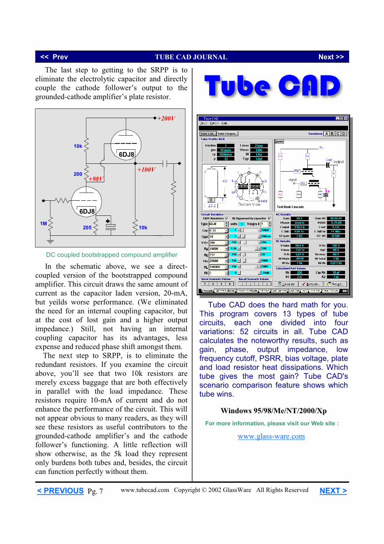
DC coupled bootstrapped compound amplifier
The last step to getting to the SRPP is to eliminate the electrolytic capacitor and directly couple the cathode follower’s output to the grounded-cathode amplifier’s plate resistor.
6DJ8
1M
+200V
6DJ8
+98V
10k
+100V
10k
200
205
In the schematic above, we see a direct-coupled version of the bootstrapped compound amplifier. This circuit draws the same amount of current as the capacitor laden version, 20-mA, but yeilds worse performance. (We eliminated the need for an internal coupling capacitor, but at the cost of lost gain and a higher output impedance.) Still, not having an internal coupling capacitor has its advantages, less expense and reduced phase shift amongst them. The next step to SRPP, is to eliminate the redundant resistors. If you examine the circuit above, you’ll see that two 10k resistors are merely excess baggage that are both effectively in parallel with the load impedance. These resistors require 10-mA of current and do not enhance the performance of the circuit. This will not appear obvious to many readers, as they will see these resistors as useful contributors to the grounded-cathode amplifier’s and the cathode follower’s functioning. A little reflection will show otherwise, as the 5k load they represent only burdens both tubes and, besides, the circuit can function perfectly without them.
Tube CAD
Tube CAD does the hard math for you. This program covers 13 types of tube circuits, each one divided into four variations: 52 circuits in all. Tube CAD calculates the noteworthy results, such as gain, phase, output impedance, low frequency cutoff, PSRR, bias voltage, plate and load resistor heat dissipations. Which tube gives the most gain? Tube CAD's scenario comparison feature shows which tube wins.
Windows 95/98/Me/NT/2000/Xp For more information, please visit our Web site :
www.glass-ware.com
<< Prev TUBE CAD JOURNAL Next >>
www.tubecad.com Copyright © 2002 GlassWare All Rights Reserved NEXT > < PREVIOUS 8 Pg.
http://www.goldpt.com
The SA-1 makes a great addition to any audio test bench. It can also be a complete preamp solution for audiophile "purists". Consider the advantages of using a Passive Preamp like the SA-1 between your CD/DVD player(s) and your power amplifier(s): The SA-1 adds no distortion to your signal path while performing the major task of most preamps - signal level control. (Active preamps add in at least some distortion.) It uses a precision 24 position stepped attenuator for low noise and excellent channel-to-channel signal level tracking. And it costs a fraction of what an active preamp costs. Arn Roatcap, Inc. 1248 Valerian Court #4 Sunnyvale, CA 94086 Phone: (408) 737-3920 E-mail: [email protected] Phone: (408) 737-3920 E-mail: [email protected]
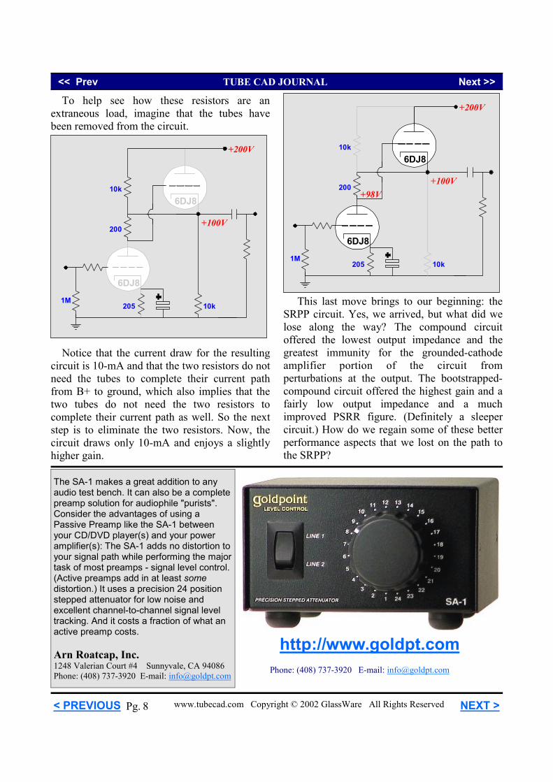
6DJ8
1M
+200V
6DJ8
+98V
10k
+100V200
205
10k
To help see how these resistors are an extraneous load, imagine that the tubes have been removed from the circuit.
6DJ8
1M
+200V
6DJ8
+100V
10k
200
205 10k
Notice that the current draw for the resulting circuit is 10-mA and that the two resistors do not need the tubes to complete their current path from B+ to ground, which also implies that the two tubes do not need the two resistors to complete their current path as well. So the next step is to eliminate the two resistors. Now, the circuit draws only 10-mA and enjoys a slightly higher gain.
This last move brings to our beginning: the SRPP circuit. Yes, we arrived, but what did we lose along the way? The compound circuit offered the lowest output impedance and the greatest immunity for the grounded-cathode amplifier portion of the circuit from perturbations at the output. The bootstrapped-compound circuit offered the highest gain and a fairly low output impedance and a much improved PSRR figure. (Definitely a sleeper circuit.) How do we regain some of these better performance aspects that we lost on the path to the SRPP?
<< Prev TUBE CAD JOURNAL Next >>
www.tubecad.com Copyright © 2002 GlassWare All Rights Reserved NEXT > < PREVIOUS 9 Pg.
The first Tube CAD Journal companion software program TCJ Filter Designer lets you design a filter or crossover (passive, solid-state or tube) without having to check out thick textbooks from the library and without having to breakout the scientific calculator. This program's goal is to provide a quick and easy display not only of the frequency response, but also of the resistor and capacitor values for a passive and active filters and crossovers. Tube crossovers are a major part of this program; both buffered and unbuffered tube based filters along with mono-polar and bipolar power supply topologies are covered. For more information, read the article "Tube-Based Crossovers" in the Tube CAD Journal. To buy now, visit GlassWare's new Yahoo! Store.
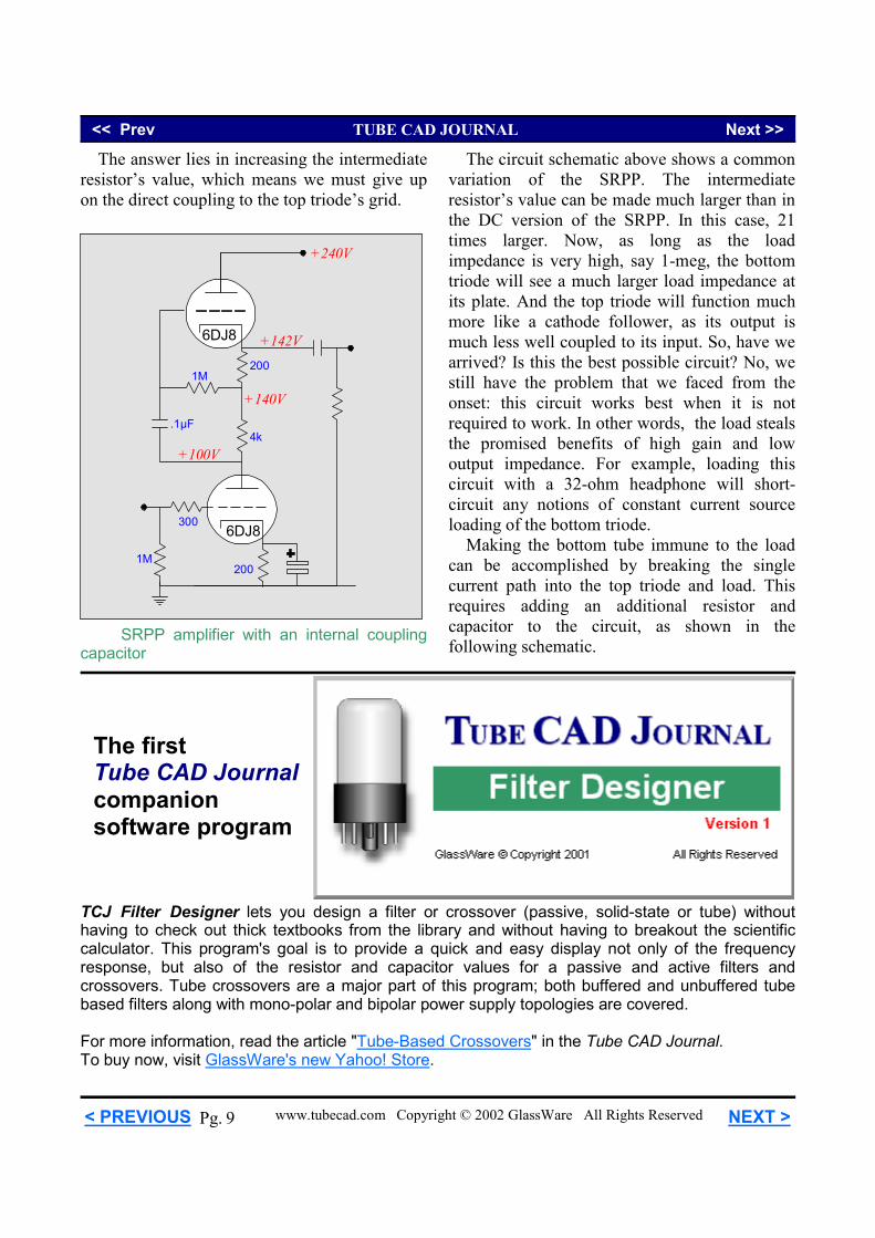
The answer lies in increasing the intermediate resistor’s value, which means we must give up on the direct coupling to the top triode’s grid.
6DJ8
1M
+240V
6DJ8
+100V4k
200
1M200
+140V
300
+142V
.1µF
SRPP amplifier with an internal coupling capacitor
The circuit schematic above shows a common variation of the SRPP. The intermediate resistor’s value can be made much larger than in the DC version of the SRPP. In this case, 21 times larger. Now, as long as the load impedance is very high, say 1-meg, the bottom triode will see a much larger load impedance at its plate. And the top triode will function much more like a cathode follower, as its output is much less well coupled to its input. So, have we arrived? Is this the best possible circuit? No, we still have the problem that we faced from the onset: this circuit works best when it is not required to work. In other words, the load steals the promised benefits of high gain and low output impedance. For example, loading this circuit with a 32-ohm headphone will short-circuit any notions of constant current source loading of the bottom triode. Making the bottom tube immune to the load can be accomplished by breaking the single current path into the top triode and load. This requires adding an additional resistor and capacitor to the circuit, as shown in the following schematic.
<< Prev TUBE CAD JOURNAL Next >>
www.tubecad.com Copyright © 2002 GlassWare All Rights Reserved NEXT > < PREVIOUS 10 Pg.
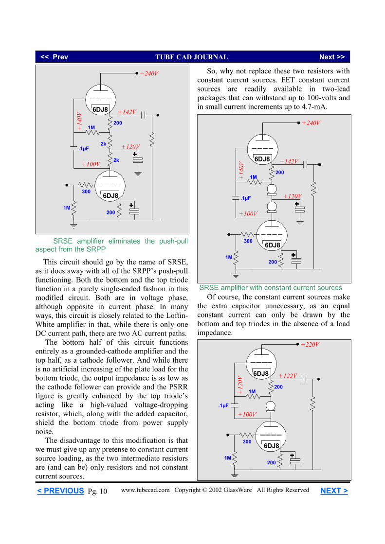
This circuit should go by the name of SRSE, as it does away with all of the SRPP’s push-pull functioning. Both the bottom and the top triode function in a purely single-ended fashion in this modified circuit. Both are in voltage phase, although opposite in current phase. In many ways, this circuit is closely related to the Loftin-White amplifier in that, while there is only one DC current path, there are two AC current paths. The bottom half of this circuit functions entirely as a grounded-cathode amplifier and the top half, as a cathode follower. And while there is no artificial increasing of the plate load for the bottom triode, the output impedance is as low as the cathode follower can provide and the PSRR figure is greatly enhanced by the top triode’s acting like a high-valued voltage-dropping resistor, which, along with the added capacitor, shield the bottom triode from power supply noise. The disadvantage to this modification is that we must give up any pretense to constant current source loading, as the two intermediate resistors are (and can be) only resistors and not constant current sources.
6DJ8
1M
+240V
6DJ8
+100V2k
200
1M200
+120V2k
+14
0V
300
+142V
.1µF
SRSE amplifier eliminates the push-pull aspect from the SRPP 6DJ8
1M
+240V
6DJ8
+100V
200
1M200
+120V
+14
0V300
+142V
.1µF
So, why not replace these two resistors with constant current sources. FET constant current sources are readily available in two-lead packages that can withstand up to 100-volts and in small current increments up to 4.7-mA.
Of course, the constant current sources make the extra capacitor unnecessary, as an equal constant current can only be drawn by the bottom and top triodes in the absence of a load impedance.
SRSE amplifier with constant current sources
6DJ8
1M
+220V
6DJ8
+100V
200
1M200
+12
0V
300
+122V
.1µF
<< Prev TUBE CAD JOURNAL Next >>
www.tubecad.com Copyright © 2002 GlassWare All Rights Reserved NEXT > < PREVIOUS 11 Pg.
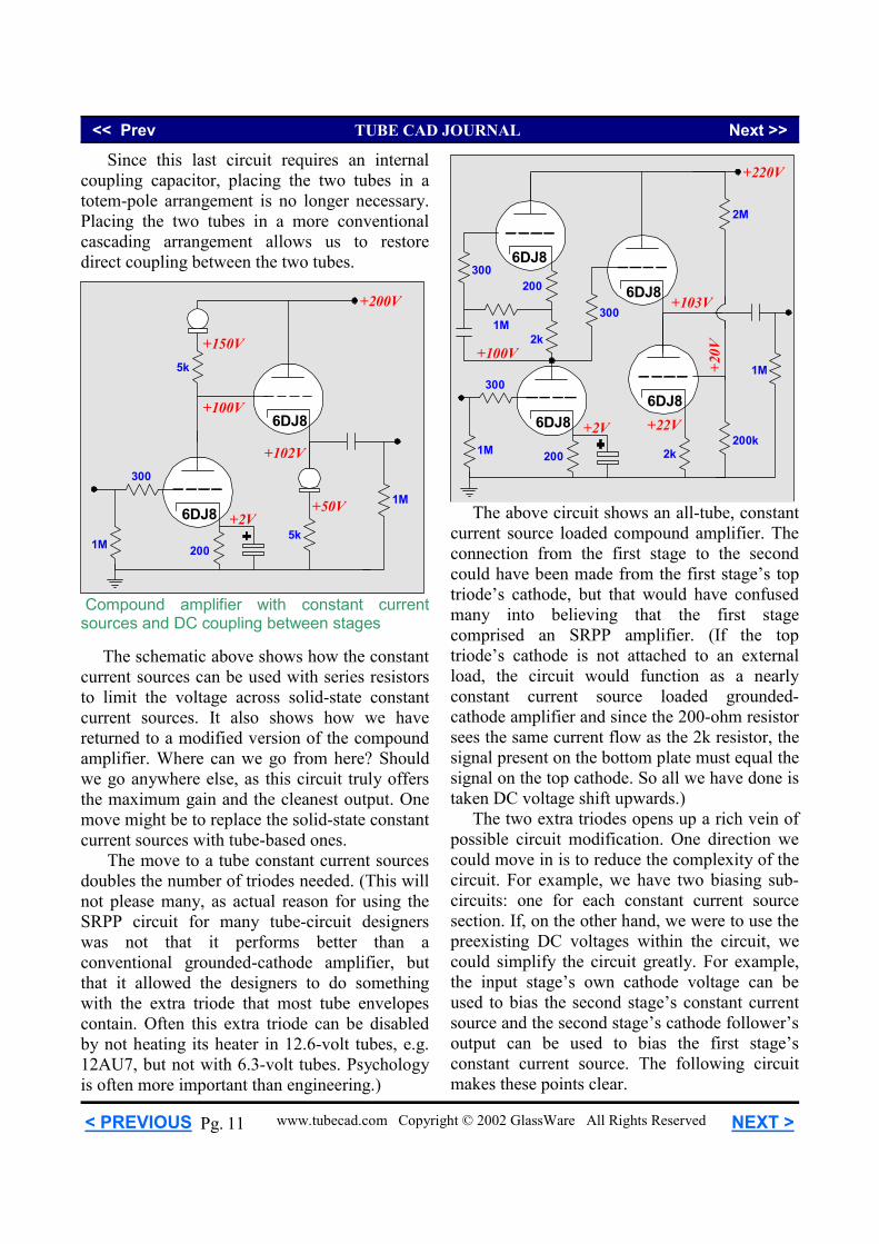
Since this last circuit requires an internal coupling capacitor, placing the two tubes in a totem-pole arrangement is no longer necessary. Placing the two tubes in a more conventional cascading arrangement allows us to restore direct coupling between the two tubes.
6DJ8
1M
+200V
6DJ8
1M
+102V
200
+2V
300
5k
5k
+50V
+150V
+100V
The schematic above shows how the constant current sources can be used with series resistors to limit the voltage across solid-state constant current sources. It also shows how we have returned to a modified version of the compound amplifier. Where can we go from here? Should we go anywhere else, as this circuit truly offers the maximum gain and the cleanest output. One move might be to replace the solid-state constant current sources with tube-based ones. The move to a tube constant current sources doubles the number of triodes needed. (This will not please many, as actual reason for using the SRPP circuit for many tube-circuit designers was not that it performs better than a conventional grounded-cathode amplifier, but that it allowed the designers to do something with the extra triode that most tube envelopes contain. Often this extra triode can be disabled by not heating its heater in 12.6-volt tubes, e.g. 12AU7, but not with 6.3-volt tubes. Psychology is often more important than engineering.)
6DJ8
1M
+220V
6DJ8
6DJ8
1M
2k
+103V
+100V
200
+22V+2V
300
2k
200
1M
300
300
+20V
200k
2M
6DJ8
Compound amplifier with constant current sources and DC coupling between stages
The above circuit shows an all-tube, constant current source loaded compound amplifier. The connection from the first stage to the second could have been made from the first stage’s top triode’s cathode, but that would have confused many into believing that the first stage comprised an SRPP amplifier. (If the top triode’s cathode is not attached to an external load, the circuit would function as a nearly constant current source loaded grounded-cathode amplifier and since the 200-ohm resistor sees the same current flow as the 2k resistor, the signal present on the bottom plate must equal the signal on the top cathode. So all we have done is taken DC voltage shift upwards.) The two extra triodes opens up a rich vein of possible circuit modification. One direction we could move in is to reduce the complexity of the circuit. For example, we have two biasing sub-circuits: one for each constant current source section. If, on the other hand, we were to use the preexisting DC voltages within the circuit, we could simplify the circuit greatly. For example, the input stage’s own cathode voltage can be used to bias the second stage’s constant current source and the second stage’s cathode follower’s output can be used to bias the first stage’s constant current source. The following circuit makes these points clear.
<< Prev TUBE CAD JOURNAL Next >>
www.tubecad.com Copyright © 2002 GlassWare All Rights Reserved NEXT > < PREVIOUS 12 Pg.
6DJ8
1M
+200V
6DJ8
6DJ86DJ8
+100V+102V
+104V400
400200
+4V
1M
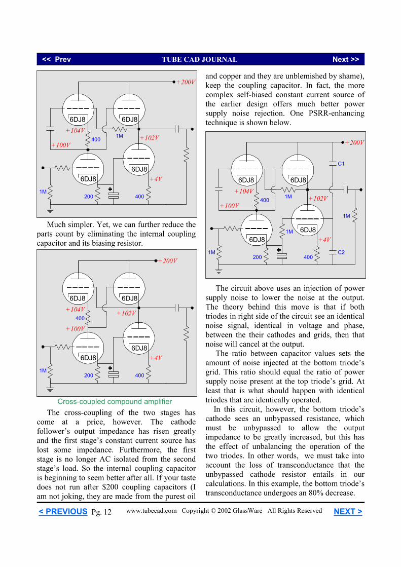
Much simpler. Yet, we can further reduce the parts count by eliminating the internal coupling capacitor and its biasing resistor.
6DJ8
1M
+200V
6DJ8
6DJ86DJ8
+100V
+102V+104V400
400200
+4V
The cross-coupling of the two stages has come at a price, however. The cathode follower’s output impedance has risen greatly and the first stage’s constant current source has lost some impedance. Furthermore, the first stage is no longer AC isolated from the second stage’s load. So the internal coupling capacitor is beginning to seem better after all. If your taste does not run after $200 coupling capacitors (I am not joking, they are made from the purest oil
Cross-coupled compound amplifier
and copper and they are unblemished by shame), keep the coupling capacitor. In fact, the more complex self-biased constant current source of the earlier design offers much better power supply noise rejection. One PSRR-enhancing technique is shown below.
6DJ8
1M
+200V
6DJ8
6DJ86DJ8
+100V+102V
+104V400
400200
+4V
1M
1M
1M
C1
C2
The circuit above uses an injection of power supply noise to lower the noise at the output. The theory behind this move is that if both triodes in right side of the circuit see an identical noise signal, identical in voltage and phase, between the their cathodes and grids, then that noise will cancel at the output. The ratio between capacitor values sets the amount of noise injected at the bottom triode’s grid. This ratio should equal the ratio of power supply noise present at the top triode’s grid. At least that is what should happen with identical triodes that are identically operated. In this circuit, however, the bottom triode’s cathode sees an unbypassed resistance, which must be unbypassed to allow the output impedance to be greatly increased, but this has the effect of unbalancing the operation of the two triodes. In other words, we must take into account the loss of transconductance that the unbypassed cathode resistor entails in our calculations. In this example, the bottom triode’s transconductance undergoes an 80% decrease.
<< Prev TUBE CAD JOURNAL Next >>
www.tubecad.com Copyright © 2002 GlassWare All Rights Reserved NEXT > < PREVIOUS 13 Pg.
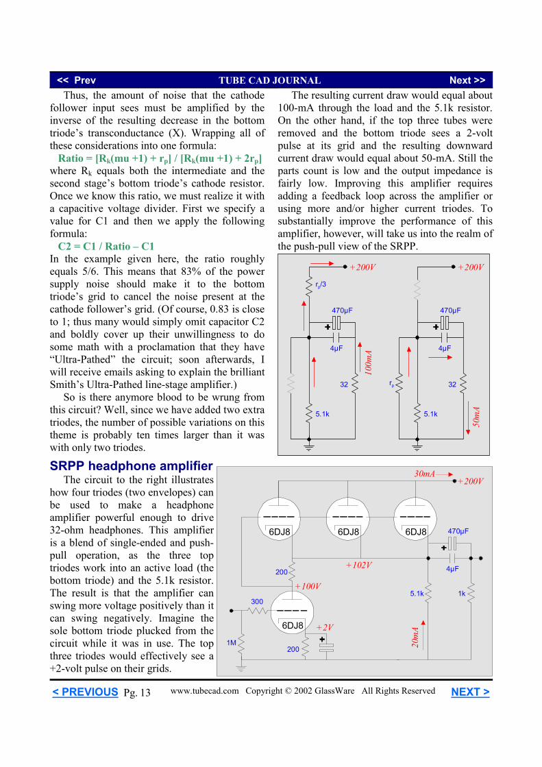
Thus, the amount of noise that the cathode follower input sees must be amplified by the inverse of the resulting decrease in the bottom triode’s transconductance (X). Wrapping all of these considerations into one formula: Ratio = [Rk(mu +1) + rp] / [Rk(mu +1) + 2rp] where Rk equals both the intermediate and the second stage’s bottom triode’s cathode resistor. Once we know this ratio, we must realize it with a capacitive voltage divider. First we specify a value for C1 and then we apply the following formula: C2 = C1 / Ratio – C1 In the example given here, the ratio roughly equals 5/6. This means that 83% of the power supply noise should make it to the bottom triode’s grid to cancel the noise present at the cathode follower’s grid. (Of course, 0.83 is close to 1; thus many would simply omit capacitor C2 and boldly cover up their unwillingness to do some math with a proclamation that they have “Ultra-Pathed” the circuit; soon afterwards, I will receive emails asking to explain the brilliant Smith’s Ultra-Pathed line-stage amplifier.) So is there anymore blood to be wrung from this circuit? Well, since we have added two extra triodes, the number of possible variations on this theme is probably ten times larger than it was with only two triodes.
6DJ8
1M
+200V
6DJ86DJ8
+100V200
200
6DJ8
3005.1k
20m
A
+102V
1k
30mA
+2V
470µF
4µF
SRPP headphone amplifier The circuit to the right illustrates how four triodes (two envelopes) can be used to make a headphone amplifier powerful enough to drive 32-ohm headphones. This amplifier is a blend of single-ended and push-pull operation, as the three top triodes work into an active load (the bottom triode) and the 5.1k resistor. The result is that the amplifier can swing more voltage positively than it can swing negatively. Imagine the sole bottom triode plucked from the circuit while it was in use. The top three triodes would effectively see a +2-volt pulse on their grids.
The resulting current draw would equal about 100-mA through the load and the 5.1k resistor. On the other hand, if the top three tubes were removed and the bottom triode sees a 2-volt pulse at its grid and the resulting downward current draw would equal about 50-mA. Still the parts count is low and the output impedance is fairly low. Improving this amplifier requires adding a feedback loop across the amplifier or using more and/or higher current triodes. To substantially improve the performance of this amplifier, however, will take us into the realm of the push-pull view of the SRPP.
+200V
100m
A
470µF
4µF
5.1k
rp/3
32
+200V
50m
A
470µF
4µF
5.1k
32rp
<< Prev TUBE CAD JOURNAL Next >>
www.tubecad.com Copyright © 2002 GlassWare All Rights Reserved NEXT > < PREVIOUS 14 Pg.
1M
300
1M
B+
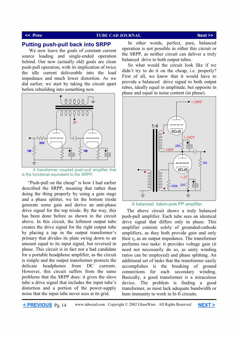
Putting push-pull back into SRPP We now leave the goals of constant current source loading and single-ended operation behind. Our new (actually old) goals are clean push-pull operation, with its implication of twice the idle current deliverable into the load impedance and much lower distortion. As we did earlier, we start by taking the circuit apart before rebuilding into something new.
A transformer coupled push-pull amplifier that is the functional equivalent to the SRPP.
“Push-pull on the cheap” is how I had earlier described the SRPP, meaning that rather than doing the thing properly by using a gain stage and a phase splitter, we let the bottom triode generate some gain and derive an anti-phase drive signal for the top triode. By the way, this has been done before as shown in the circuit above. In this circuit, the leftmost output tube creates the drive signal for the right output tube by placing a tap in the output transformer’s primary that divides its plate swing down to an amount equal to its input signal, but reversed in phase. This circuit is in fact not a bad candidate for a portable headphone amplifier, as the circuit is simple and the output transformer protects the delicate headphones from DC currents. However, this circuit suffers from the same problems that the SRPP does: it gives the slave tube a drive signal that includes the input tube’s distortion and a portion of the power-supply noise that the input tube never sees at its grid.
In other words, perfect, pure, balanced operation is not possible in either this circuit or the SRPP, as neither circuit can deliver a truly balanced drive to both output tubes. So what would the circuit look like if we didn’t try to do it on the cheap, i.e. properly? First of all, we know that it would have to provide a balanced drive signal to both output tubes, ideally equal in amplitude, but opposite in phase and equal in noise content (in phase).
+200V
+100V
6DJ8
6DJ8
100k
1M
+2V
200
+102V
200
1:4
The above circuit shows a truly balanced push-pull amplifier. Each tube sees an identical drive signal that differs only in phase. This amplifier consists solely of grounded-cathode amplifiers, as they both provide gain and only their rp as an output impedance. The transformer performs two tasks: it provides voltage gain (it need not necessarily do so, as unity winding ratios can be employed) and phase splitting. An additional set of tasks that the transformer easily accomplishes is the breaking of ground connections for each secondary winding. Basically, a good transformer is a miraculous device. The problem is finding a good transformer, as most lack adequate bandwidth or hum immunity to work in hi-fi circuits.
A balanced totem-pole PP amplifier
<< Prev TUBE CAD JOURNAL Next >>
www.tubecad.com Copyright © 2002 GlassWare All Rights Reserved NEXT > < PREVIOUS 15 Pg.
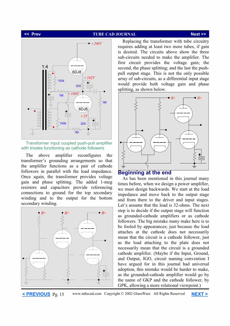
The above amplifier reconfigures the transformer’s grounding arrangements so that the amplifier functions as a pair of cathode followers in parallel with the load impedance. Once again, the transformer provides voltage gain and phase splitting. The added 1-meg resistors and capacitors provide referencing connections to ground for the top secondary winding and to the output for the bottom secondary winding.
B+B+ B+
+200V
+100V
6DJ8
6DJ8
100k
1M
+2V
200
+102V
200
1:4
1M
1M
100k
Transformer input coupled push-pull amplifier with triodes functioning as cathode followers
Replacing the transformer with tube circuitry requires adding at least two more tubes, if gain is desired. The circuits above show the three sub-circuits needed to make the amplifier. The first circuit provides the voltage gain; the second, the phase splitting; and the last the push-pull output stage. This is not the only possible array of sub-circuits, as a differential input stage would provide both voltage gain and phase splitting, as shown below.
B+B+
Beginning at the end As has been mentioned in this journal many times before, when we design a power amplifier, we must design backwards. We start at the load impedance and move back to the output stage and from there to the driver and input stages. Let’s assume that the load is 32-ohms. The next step is to decide if the output stage will function as grounded-cathode amplifiers or as cathode followers. The big mistake many make here is to be fooled by appearances; just because the load attaches at the cathode does not necessarily mean that the circuit is a cathode follower, just as the load attaching to the plate does not necessarily mean that the circuit is a grounded cathode amplifier. (Maybe if the Input, Ground, and Output, IGO, circuit naming convention I have argued for in this journal had universal adoption, this mistake would be harder to make, as the grounded-cathode amplifier would go by the name of GKP and the cathode follower, by GPK, allowing a more relational viewpoint.)
<< Prev TUBE CAD JOURNAL Next >>
www.tubecad.com Copyright © 2002 GlassWare All Rights Reserved NEXT > < PREVIOUS 16 Pg.
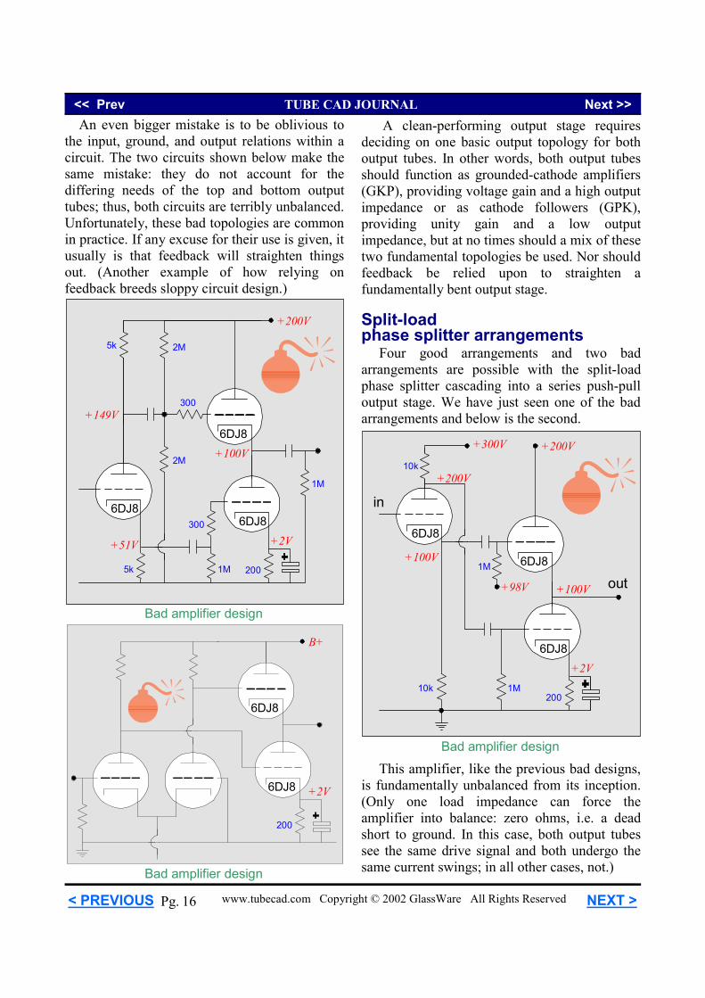
An even bigger mistake is to be oblivious to the input, ground, and output relations within a circuit. The two circuits shown below make the same mistake: they do not account for the differing needs of the top and bottom output tubes; thus, both circuits are terribly unbalanced. Unfortunately, these bad topologies are common in practice. If any excuse for their use is given, it usually is that feedback will straighten things out. (Another example of how relying on feedback breeds sloppy circuit design.)
+200V
+100V
5k
6DJ86DJ8
6DJ8
+51V
+149V
5k 1M
1M
300
300
+2V
200
2M
2M
B+
6DJ8
6DJ8
200
+2V
Bad amplifier design
Bad amplifier design
A clean-performing output stage requires deciding on one basic output topology for both output tubes. In other words, both output tubes should function as grounded-cathode amplifiers (GKP), providing voltage gain and a high output impedance or as cathode followers (GPK), providing unity gain and a low output impedance, but at no times should a mix of these two fundamental topologies be used. Nor should feedback be relied upon to straighten a fundamentally bent output stage. Split-load phase splitter arrangements Four good arrangements and two bad arrangements are possible with the split-load phase splitter cascading into a series push-pull output stage. We have just seen one of the bad arrangements and below is the second.
+200V
+100V
10k
6DJ8
6DJ8
6DJ8
10k 1M
+2V
200
in
out
+200V
+300V
1M
+98V
+100V
This amplifier, like the previous bad designs, is fundamentally unbalanced from its inception. (Only one load impedance can force the amplifier into balance: zero ohms, i.e. a dead short to ground. In this case, both output tubes see the same drive signal and both undergo the same current swings; in all other cases, not.)
Bad amplifier design
<< Prev TUBE CAD JOURNAL Next >>
www.tubecad.com Copyright © 2002 GlassWare All Rights Reserved NEXT > < PREVIOUS 17 Pg.
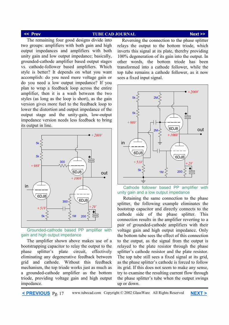
The remaining four good designs divide into two groups: amplifiers with both gain and high output impedances and amplifiers with both unity gain and low output impedance; basically, grounded-cathode amplifier based output stages vs. cathode-follower based amplifiers. Which style is better? It depends on what you want accomplish: do you need more voltage gain or do you need a low output impedance? If you plan to wrap a feedback loop across the entire amplifier, then it is a wash between the two styles (as long as the loop is short), as the gain version gives more fuel to the feedback loop to lower the distortion and output impedance of the output stage and the unity-gain, low-output impedance version needs less feedback to bring its output in line.
+200V
+100V
5k
6DJ86DJ8
6DJ8
+51V
+98V
5k 1M
300
300
+2V
200
5k
in
out
+200V
+100V
5k
6DJ86DJ8
6DJ8
+51V
+98V
5k1M
+2V
200
5k
in
out
2M
2M
Grounded-cathode based PP amplifier with gain and high output impedance The amplifier shown above makes use of a bootstrapping capacitor to relay the output to the phase splitter’s plate circuit, effectively eliminating any degenerative feedback between grid and cathode. Without this feedback mechanism, the top triode works just as much as a grounded-cathode amplifier as the bottom triode, providing voltage gain and high output impedance.
Reversing the connection to the phase splitter relays the output to the bottom triode, which inverts this signal at its plate, thereby providing 100% degeneration of its gain into the output. In other words, the bottom triode has been transformed into a cathode follower, while the top tube remains a cathode follower, as it now sees a fixed input signal.
Retaining the same connection to the phase splitter, the following example eliminates the bootstrap capacitor and directly connects to the cathode side of the phase splitter. This connection results in the amplifier reverting to a pair of grounded-cathode amplifiers with their voltage gain and high output impedance. Only the bottom tube sees the effect of this connection to the output, as the signal from the output is relayed to the plate resistor through the phase splitter’s cathode resistor and the plate resistor. The top tube still sees a fixed signal at its grid, as the phase splitter’s cathode is forced to follow its grid. If this does not seem to make any sense, try to examine the resulting current flow through the phase splitter’s tube when the output swings up or down.
Cathode follower based PP amplifier with unity gain and a low output impedance
<< Prev TUBE CAD JOURNAL Next >>
www.tubecad.com Copyright © 2002 GlassWare All Rights Reserved NEXT > < PREVIOUS 18 Pg.
Bad amplifier design
+200V
+100V
10k
6DJ8
6DJ8
6DJ8
10k 1M
+2V
200
10k
in
out
+400V
+200V
+300V
1M
+98V
+200V
+100V
10k
6DJ8
6DJ8
6DJ8
10k 1M
+2V
200
10k
in
out
+400V
+200V
+300V
1M
+98V
Cathode follower based PP amplifier
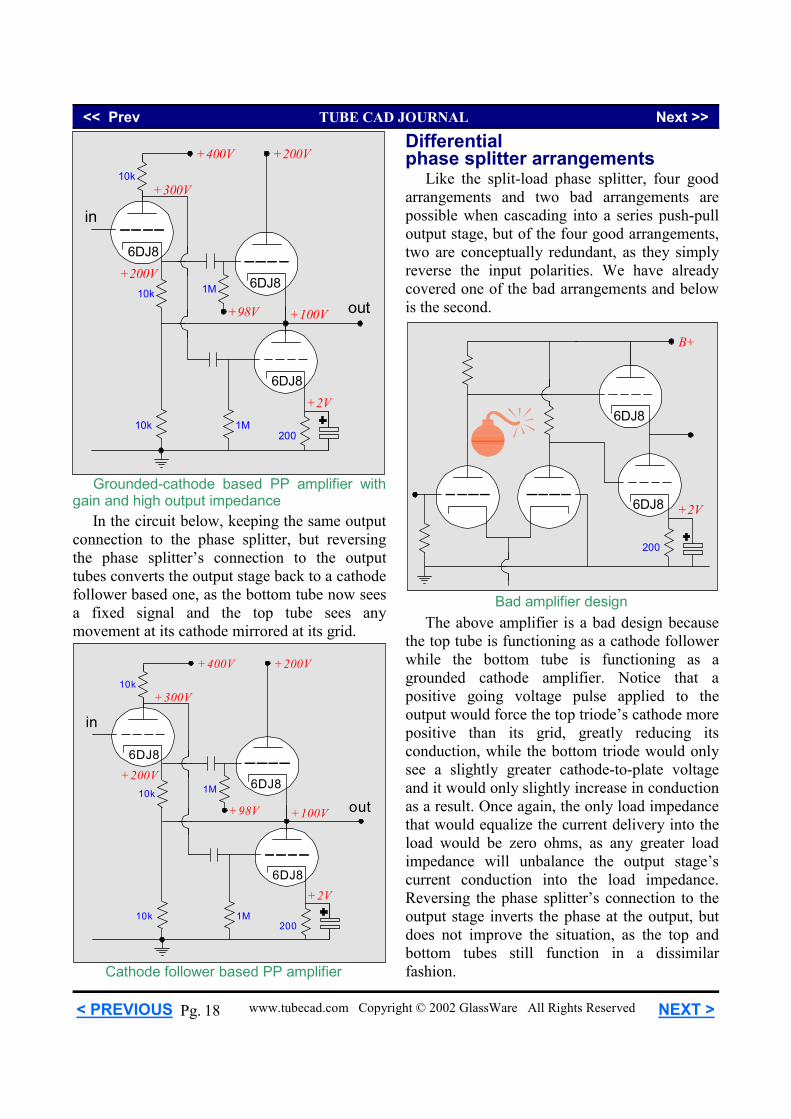
Grounded-cathode based PP amplifier with gain and high output impedance In the circuit below, keeping the same output connection to the phase splitter, but reversing the phase splitter’s connection to the output tubes converts the output stage back to a cathode follower based one, as the bottom tube now sees a fixed signal and the top tube sees any movement at its cathode mirrored at its grid.
Differential phase splitter arrangements Like the split-load phase splitter, four good arrangements and two bad arrangements are possible when cascading into a series push-pull output stage, but of the four good arrangements, two are conceptually redundant, as they simply reverse the input polarities. We have already covered one of the bad arrangements and below is the second.
B+
6DJ8
6DJ8
200
+2V
The above amplifier is a bad design because the top tube is functioning as a cathode follower while the bottom tube is functioning as a grounded cathode amplifier. Notice that a positive going voltage pulse applied to the output would force the top triode’s cathode more positive than its grid, greatly reducing its conduction, while the bottom triode would only see a slightly greater cathode-to-plate voltage and it would only slightly increase in conduction as a result. Once again, the only load impedance that would equalize the current delivery into the load would be zero ohms, as any greater load impedance will unbalance the output stage’s current conduction into the load impedance. Reversing the phase splitter’s connection to the output stage inverts the phase at the output, but does not improve the situation, as the top and bottom tubes still function in a dissimilar fashion.
<< Prev TUBE CAD JOURNAL Next >>
www.tubecad.com Copyright © 2002 GlassWare All Rights Reserved NEXT > < PREVIOUS 19 Pg.
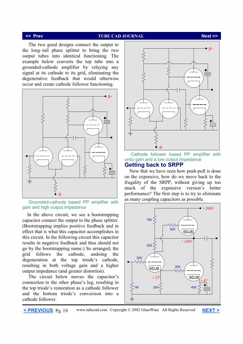
Cathode follower based PP amplifier with unity gain and a low output impedance
Grounded-cathode based PP amplifier with gain and high output impedance
B+
B-
B+
B-
The two good designs connect the output to the long–tail phase splitter to bring the two output tubes into identical functioning. The example below converts the top tube into a grounded-cathode amplifier by relaying any signal at its cathode to its grid, eliminating the degenerative feedback that would otherwise occur and create cathode follower functioning.
In the above circuit, we see a bootstrapping capacitor connect the output to the phase splitter. (Bootstrapping implies positive feedback and in effect that is what this capacitor accomplishes in this circuit. In the following circuit this capacitor results in negative feedback and thus should not go by the bootstrapping name.) So arranged, the grid follows the cathode, undoing the degeneration at the top triode’s cathode, resulting in both voltage gain and a higher output impedance (and greater distortion). The circuit below moves the capacitor’s connection to the other phase’s leg, resulting in the top triode’s restoration as a cathode follower and the bottom triode’s conversion into a cathode follower.
Getting back to SRPP Now that we have seen how push-pull is done on the expensive, how do we move back to the frugality of the SRPP, without giving up too much of the expensive version’s better performance? The first step is to try to eliminate as many coupling capacitors as possible.
+200V
+100V
6DJ8
200
300
300
1M
200
+2V
300
+4V400
6DJ8
6DJ8
10k
<< Prev TUBE CAD JOURNAL Next >>
www.tubecad.com Copyright © 2002 GlassWare All Rights Reserved NEXT > < PREVIOUS 20 Pg.
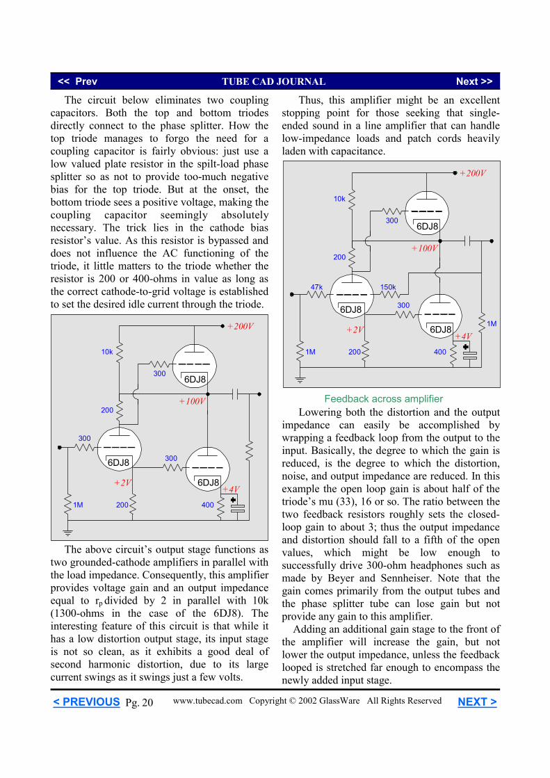
The circuit below eliminates two coupling capacitors. Both the top and bottom triodes directly connect to the phase splitter. How the top triode manages to forgo the need for a coupling capacitor is fairly obvious: just use a low valued plate resistor in the spilt-load phase splitter so as not to provide too-much negative bias for the top triode. But at the onset, the bottom triode sees a positive voltage, making the coupling capacitor seemingly absolutely necessary. The trick lies in the cathode bias resistor’s value. As this resistor is bypassed and does not influence the AC functioning of the triode, it little matters to the triode whether the resistor is 200 or 400-ohms in value as long as the correct cathode-to-grid voltage is established to set the desired idle current through the triode.
+200V
+100V
6DJ8
200
300
300
1M
200
+2V
300
+4V400
6DJ8
6DJ8
10k
The above circuit’s output stage functions as two grounded-cathode amplifiers in parallel with the load impedance. Consequently, this amplifier provides voltage gain and an output impedance equal to rp divided by 2 in parallel with 10k (1300-ohms in the case of the 6DJ8). The interesting feature of this circuit is that while it has a low distortion output stage, its input stage is not so clean, as it exhibits a good deal of second harmonic distortion, due to its large current swings as it swings just a few volts.
Thus, this amplifier might be an excellent stopping point for those seeking that single-ended sound in a line amplifier that can handle low-impedance loads and patch cords heavily laden with capacitance.
+200V
+100V
6DJ8
200
300
300
1M
200
+2V
47k
+4V400
6DJ8
6DJ8
10k
150k
1M
Lowering both the distortion and the output impedance can easily be accomplished by wrapping a feedback loop from the output to the input. Basically, the degree to which the gain is reduced, is the degree to which the distortion, noise, and output impedance are reduced. In this example the open loop gain is about half of the triode’s mu (33), 16 or so. The ratio between the two feedback resistors roughly sets the closed-loop gain to about 3; thus the output impedance and distortion should fall to a fifth of the open values, which might be low enough to successfully drive 300-ohm headphones such as made by Beyer and Sennheiser. Note that the gain comes primarily from the output tubes and the phase splitter tube can lose gain but not provide any gain to this amplifier. Adding an additional gain stage to the front of the amplifier will increase the gain, but not lower the output impedance, unless the feedback looped is stretched far enough to encompass the newly added input stage.
Feedback across amplifier
<< Prev TUBE CAD JOURNAL Next >>
www.tubecad.com Copyright © 2002 GlassWare All Rights Reserved NEXT > < PREVIOUS 21 Pg.
+200V
+100V
6DJ8
200
300
300
1M
200
+2V
300
+4V400
6DJ8
6DJ8
5k
300
10k
6DJ8
100
+2V
9.8k
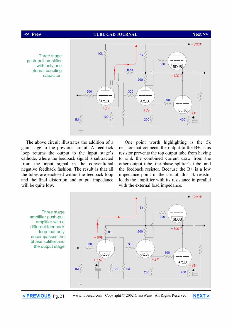
The above circuit illustrates the addition of a gain stage to the previous circuit. A feedback loop returns the output to the input stage’s cathode, where the feedback signal is subtracted from the input signal in the conventional negative feedback fashion. The result is that all the tubes are enclosed within the feedback loop and the final distortion and output impedance will be quite low.
Three stage push-pull amplifier
with only one internal coupling
capacitor.
+200V
+100V
6DJ8
200
300
300
1M
200
+2V
300
+4V400
6DJ8
6DJ8
5k
300
1k
6DJ8
190
+1.9V
1M
+90V
Three stage amplifier push-pull
amplifier with a different feedback
loop that only encompasses the phase splitter and
the output stage
One point worth highlighting is the 5k resistor that connects the output to the B+. This resistor prevents the top output tube from having to sink the combined current draw from the other output tube, the phase splitter’s tube, and the feedback resistor. Because the B+ is a low impedance point in the circuit, this 5k resistor loads the amplifier with its resistance in parallel with the external load impedance.
<< Prev TUBE CAD JOURNAL Next >>
www.tubecad.com Copyright © 2002 GlassWare All Rights Reserved NEXT > < PREVIOUS 22 Pg.
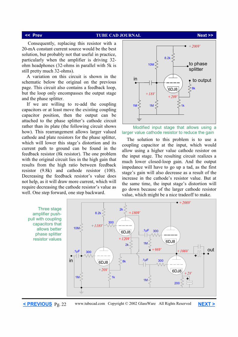
Three stage amplifier push-
pull with coupling capacitors that
allows better phase splitter
resistor values
Consequently, replacing this resistor with a 20-mA constant current source would be the best solution, but probably not that useful in practice, particularly when the amplifier is driving 32-ohm headphones (32-ohms in parallel with 5k is still pretty much 32-ohms). A variation on this circuit is shown in the schematic below the original on the previous page. This circuit also contains a feedback loop, but the loop only encompasses the output stage and the phase splitter. If we are willing to re-add the coupling capacitors or at least move the existing coupling capacitor position, then the output can be attached to the phase splitter’s cathode circuit rather than its plate (the following circuit shows how). This rearrangement allows larger valued cathode and plate resistors for the phase splitter, which will lower this stage’s distortion and its current path to ground can be found in the feedback resistor (8k resistor). The one problem with the original circuit lies in the high gain that results from the high ratio between feedback resistor (9.8k) and cathode resistor (100). Decreasing the feedback resistor’s value does not help, as it will draw more current, which will require decreasing the cathode resistor’s value as well. One step forward, one step backward.
+200V
+100V
2k
6DJ8
6DJ8
6DJ8
8k
1M
+2V
200
2k
in
out
+120V
+180V
1M
+98V
1M
300
8.2k
6DJ8
300
1k
+20V
+118V300
300.1µF
.1µF10M
.1µF
The solution to this problem is to use a coupling capacitor at the input, which would allow using a higher value cathode resistor on the input stage. The resulting circuit realizes a much lower closed-loop gain. And the output impedance will have to go up a tad, as the first stage’s gain will also decrease as a result of the increase in the cathode’s resistor value. But at the same time, the input stage’s distortion will go down because of the larger cathode resistor value, which might be a nice tradeoff to make.
in
1M
8.2k
6DJ8
1k
+20V+18V
8k
to output
10M
1M
to phasesplitter
+200V
Modified input stage that allows using a larger value cathode resistor to reduce the gain
<< Prev TUBE CAD JOURNAL Next >>
www.tubecad.com Copyright © 2002 GlassWare All Rights Reserved NEXT > < PREVIOUS 23 Pg.
+200V
+100V
6DJ8
6DJ8
1M
300
+2V
200
300
1M1.1k
+178V
+100V
1M
300
10k
7.8k
+100V
10k
40k
+20V+20V +22V6DJ86DJ8
2.2k
200k
1.8M
.47µF
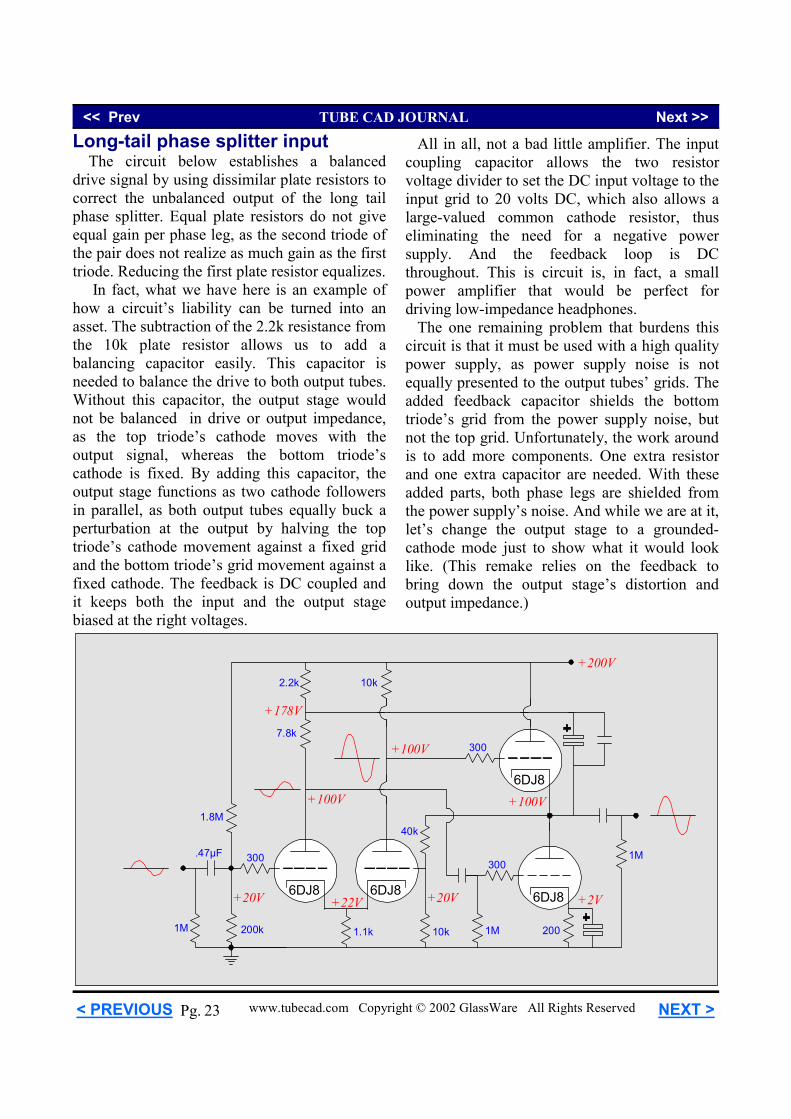
Long-tail phase splitter input The circuit below establishes a balanced drive signal by using dissimilar plate resistors to correct the unbalanced output of the long tail phase splitter. Equal plate resistors do not give equal gain per phase leg, as the second triode of the pair does not realize as much gain as the first triode. Reducing the first plate resistor equalizes. In fact, what we have here is an example of how a circuit’s liability can be turned into an asset. The subtraction of the 2.2k resistance from the 10k plate resistor allows us to add a balancing capacitor easily. This capacitor is needed to balance the drive to both output tubes. Without this capacitor, the output stage would not be balanced in drive or output impedance, as the top triode’s cathode moves with the output signal, whereas the bottom triode’s cathode is fixed. By adding this capacitor, the output stage functions as two cathode followers in parallel, as both output tubes equally buck a perturbation at the output by halving the top triode’s cathode movement against a fixed grid and the bottom triode’s grid movement against a fixed cathode. The feedback is DC coupled and it keeps both the input and the output stage biased at the right voltages.
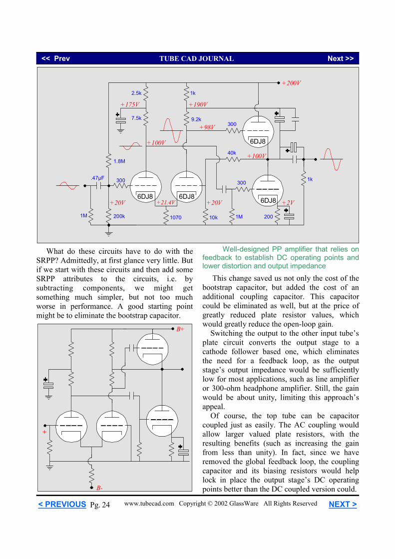
All in all, not a bad little amplifier. The input coupling capacitor allows the two resistor voltage divider to set the DC input voltage to the input grid to 20 volts DC, which also allows a large-valued common cathode resistor, thus eliminating the need for a negative power supply. And the feedback loop is DC throughout. This is circuit is, in fact, a small power amplifier that would be perfect for driving low-impedance headphones. The one remaining problem that burdens this circuit is that it must be used with a high quality power supply, as power supply noise is not equally presented to the output tubes’ grids. The added feedback capacitor shields the bottom triode’s grid from the power supply noise, but not the top grid. Unfortunately, the work around is to add more components. One extra resistor and one extra capacitor are needed. With these added parts, both phase legs are shielded from the power supply’s noise. And while we are at it, let’s change the output stage to a grounded-cathode mode just to show what it would look like. (This remake relies on the feedback to bring down the output stage’s distortion and output impedance.)
<< Prev TUBE CAD JOURNAL Next >>
www.tubecad.com Copyright © 2002 GlassWare All Rights Reserved NEXT > < PREVIOUS 24 Pg.
+200V
+100V
6DJ8
6DJ8
1k
300
+2V
200
300
1M1070
+175V
+98V
1M
300
9.2k7.5k
+100V
10k
40k
+20V +21.4V6DJ86DJ8
2.5k
200k
1.8M
.47µF
1k
+190V
+20V
What do these circuits have to do with the SRPP? Admittedly, at first glance very little. But if we start with these circuits and then add some SRPP attributes to the circuits, i.e. by subtracting components, we might get something much simpler, but not too much worse in performance. A good starting point might be to eliminate the bootstrap capacitor.
B+
+
B-
This change saved us not only the cost of the bootstrap capacitor, but added the cost of an additional coupling capacitor. This capacitor could be eliminated as well, but at the price of greatly reduced plate resistor values, which would greatly reduce the open-loop gain. Switching the output to the other input tube’s plate circuit converts the output stage to a cathode follower based one, which eliminates the need for a feedback loop, as the output stage’s output impedance would be sufficiently low for most applications, such as line amplifier or 300-ohm headphone amplifier. Still, the gain would be about unity, limiting this approach’s appeal. Of course, the top tube can be capacitor coupled just as easily. The AC coupling would allow larger valued plate resistors, with the resulting benefits (such as increasing the gain from less than unity). In fact, since we have removed the global feedback loop, the coupling capacitor and its biasing resistors would help lock in place the output stage’s DC operating points better than the DC coupled version could.
Well-designed PP amplifier that relies on feedback to establish DC operating points and lower distortion and output impedance
<< Prev TUBE CAD JOURNAL Next >>
www.tubecad.com Copyright © 2002 GlassWare All Rights Reserved NEXT > < PREVIOUS 25 Pg.
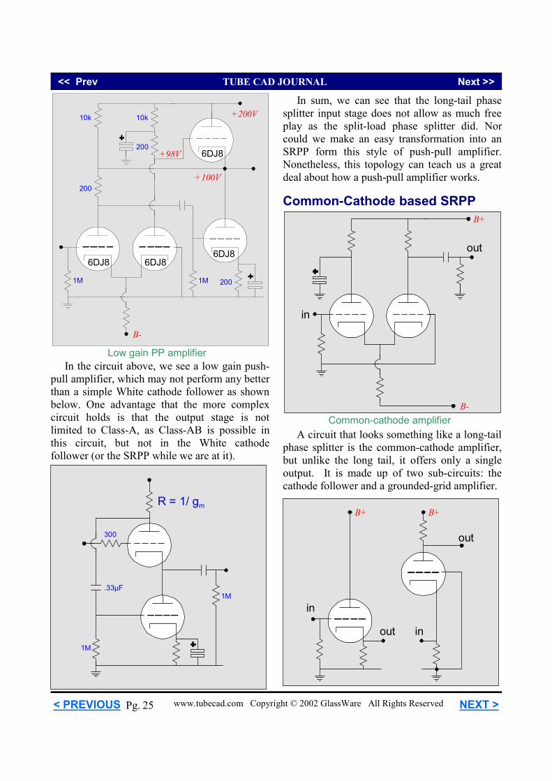
In the circuit above, we see a low gain push-pull amplifier, which may not perform any better than a simple White cathode follower as shown below. One advantage that the more complex circuit holds is that the output stage is not limited to Class-A, as Class-AB is possible in this circuit, but not in the White cathode follower (or the SRPP while we are at it).
B-
6DJ8
6DJ86DJ86DJ8
2001M 1M
200
200
+200V
+100V
10k 10k
+98V
Low gain PP amplifier
1M
1M
300
.33µF
R = 1/ gm
In sum, we can see that the long-tail phase splitter input stage does not allow as much free play as the split-load phase splitter did. Nor could we make an easy transformation into an SRPP form this style of push-pull amplifier. Nonetheless, this topology can teach us a great deal about how a push-pull amplifier works. Common-Cathode based SRPP
A circuit that looks something like a long-tail phase splitter is the common-cathode amplifier, but unlike the long tail, it offers only a single output. It is made up of two sub-circuits: the cathode follower and a grounded-grid amplifier.
B+B+
in
in
out
out
B+
B-
out
in
Common-cathode amplifier
<< Prev TUBE CAD JOURNAL Next >>
www.tubecad.com Copyright © 2002 GlassWare All Rights Reserved NEXT > < PREVIOUS 26 Pg.
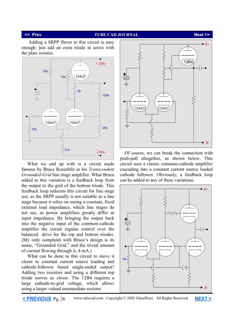
Adding a SRPP flavor to this circuit is easy enough: just add an extra triode in series with the plate resistor.
What we end up with is a circuit made famous by Bruce Rozenblit in his Transcendent Grounded-Grid line stage amplifier. What Bruce added to this variation is a feedback loop from the output to the grid of the bottom triode. This feedback loop redeems this circuit for line stage use, as the SRPP usually is not suitable as a line stage because it relies on seeing a constant, fixed external load impedance, which line stages do not see, as power amplifiers greatly differ in input impedance. By bringing the output back into the negative input of the common-cathode amplifier the circuit regains control over the balanced drive for the top and bottom triodes. (My only complaint with Bruce’s design is its name, “Grounded Grid,” and the trivial amount of current flowing through it, 4-mA.) What can be done to this circuit to move it closer to constant current source loading and cathode-follower based single-ended output? Adding two resistors and using a different top triode moves us closer. The 12B4 requires a large cathode-to-grid voltage, which allows using a larger valued intermediate resistor.
Of course, we can break the connection with push-pull altogether, as shown below. This circuit uses a classic common-cathode amplifier cascading into a constant current source loaded cathode follower. Obviously, a feedback loop can be added to any of these variations.
B+
B-
12B4
12AX712AX7
B+
B-
1M
+200v
-200v
12AU712AU7
12AU730k
3k
51k
100k
20k10k
10k
<< Prev TUBE CAD JOURNAL Next >>
www.tubecad.com Copyright © 2002 GlassWare All Rights Reserved NEXT > < PREVIOUS 27 Pg.
6DJ8
1M
+200V
6DJ8
6DJ86DJ8
+100V200
200
6DJ8
6DJ8
+102V
300
+102.7V+102.7V
Z=2.7v Z=2.7v
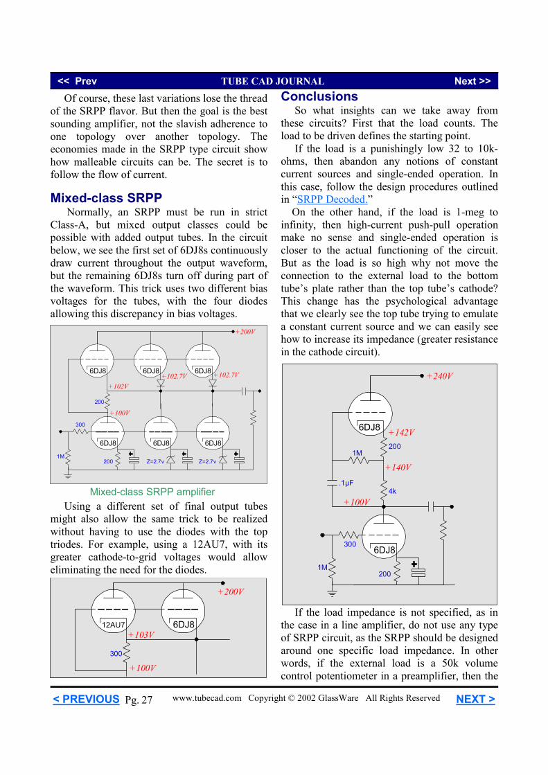
Mixed-class SRPP amplifier
6DJ812AU7
+100V300
+103V
+200V
Of course, these last variations lose the thread of the SRPP flavor. But then the goal is the best sounding amplifier, not the slavish adherence to one topology over another topology. The economies made in the SRPP type circuit show how malleable circuits can be. The secret is to follow the flow of current. Mixed-class SRPP Normally, an SRPP must be run in strict Class-A, but mixed output classes could be possible with added output tubes. In the circuit below, we see the first set of 6DJ8s continuously draw current throughout the output waveform, but the remaining 6DJ8s turn off during part of the waveform. This trick uses two different bias voltages for the tubes, with the four diodes allowing this discrepancy in bias voltages.
Using a different set of final output tubes might also allow the same trick to be realized without having to use the diodes with the top triodes. For example, using a 12AU7, with its greater cathode-to-grid voltages would allow eliminating the need for the diodes.
Conclusions So what insights can we take away from these circuits? First that the load counts. The load to be driven defines the starting point. If the load is a punishingly low 32 to 10k-ohms, then abandon any notions of constant current sources and single-ended operation. In this case, follow the design procedures outlined in “SRPP Decoded.” On the other hand, if the load is 1-meg to infinity, then high-current push-pull operation make no sense and single-ended operation is closer to the actual functioning of the circuit. But as the load is so high why not move the connection to the external load to the bottom tube’s plate rather than the top tube’s cathode? This change has the psychological advantage that we clearly see the top tube trying to emulate a constant current source and we can easily see how to increase its impedance (greater resistance in the cathode circuit).
6DJ8
1M
+240V
6DJ8
+100V4k
200
1M200
+140V
300
+142V
.1µF
If the load impedance is not specified, as in the case in a line amplifier, do not use any type of SRPP circuit, as the SRPP should be designed around one specific load impedance. In other words, if the external load is a 50k volume control potentiometer in a preamplifier, then the
<< Prev TUBE CAD JOURNAL Next >>
www.tubecad.com Copyright © 2002 GlassWare All Rights Reserved NEXT > < PREVIOUS 28 Pg.
SRPP circuit can be optimized for that load impedance, as it is fixed. But if the external load is a power amplifier, then the load impedance might be as low as 2k and as high as 1-meg. Of course, if you only plan on using the line amplifier to drive one amplifier and only one amplifier, then you can certainly optimize the circuit for this amplifier. And equally obvious, no manufacturer of a line stage could optimize the SRPP for all amplifiers and shouldn’t use the circuit for this application. Wait a minute, doesn't such and such make a line amplifier that uses an SRPP output stage and it sounds great? Sure, but does it sound great working into 2k or 1-meg? In the same vein, if the load is highly reactive, for example electrostatic headphones or twenty feet of patch cord, do not use a generic SRPP, as the circuit relies on a purely resistive load for proper functioning (in previous Tube CAD Journal articles, techniques for driving reactive loads are explored).
300
1M
1M
.33µF
1nF
In sum, the SRPP circuit has its uses, but those uses are limited. Where money and space allow, better more complicated circuits can be used to better effect than the SRPP; but where dirty and cheap are needed and where the load impedance is fixed and purely resistive, the SRPP is a good choice.
6DJ8
2k
+120V
6DJ847k
+100V
200
150
1M
.33µF
10.9k
+118V
102k
118k 6DJ8
2k
+120V
+220V
6DJ8
1M
+100V
200
300
1M
.33µF
1M
+118V
.03µF
.01µF
81k
.33µF
.33µF1µF
6DJ8
6DJ8
+100V
275
+103V
300
1M
1M
+220V
200
+2V
TL783
+220V +230V +280V +340V
126
22.9k
850166
.001µF
inout
adj
100µF
Z=100v
.33µF
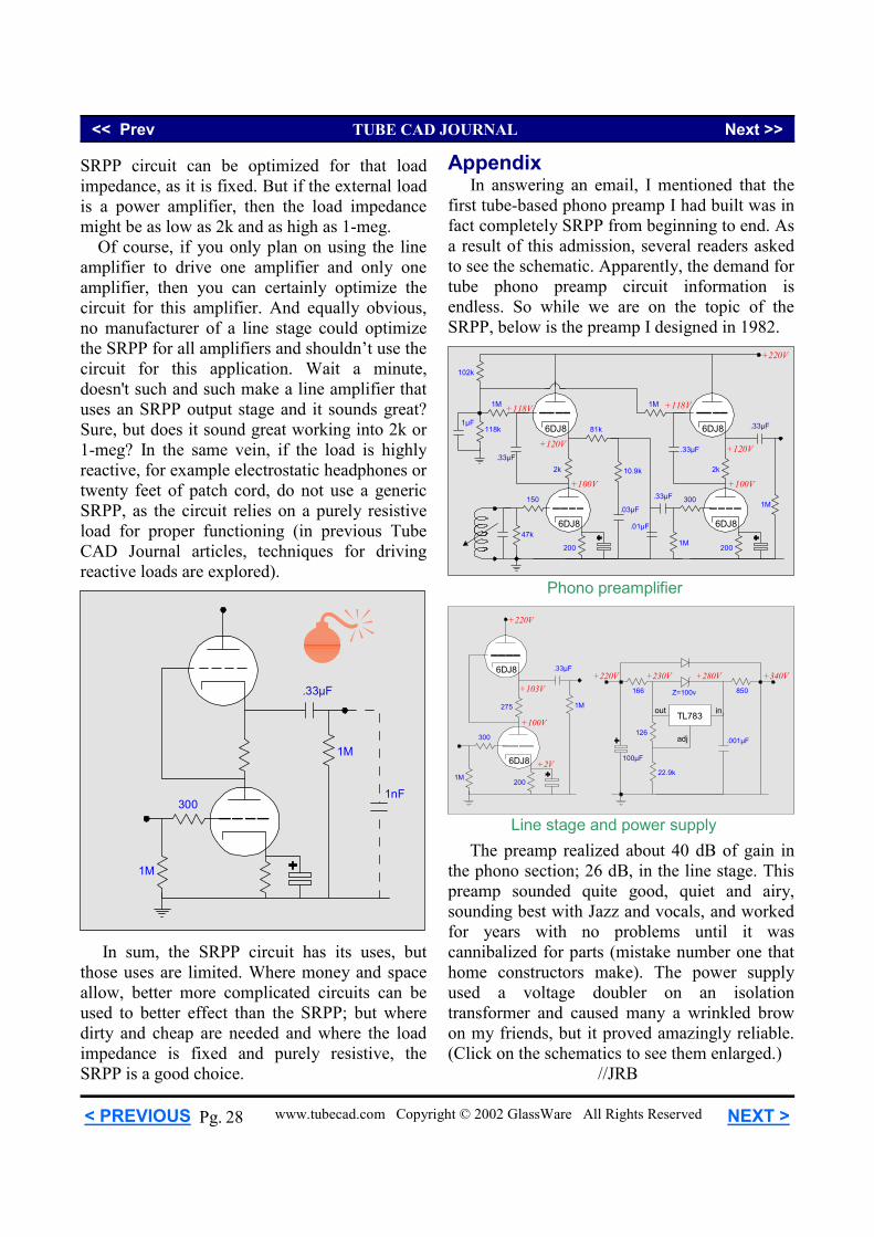
Phono preamplifier
Line stage and power supply
Appendix In answering an email, I mentioned that the first tube-based phono preamp I had built was in fact completely SRPP from beginning to end. As a result of this admission, several readers asked to see the schematic. Apparently, the demand for tube phono preamp circuit information is endless. So while we are on the topic of the SRPP, below is the preamp I designed in 1982.
The preamp realized about 40 dB of gain in the phono section; 26 dB, in the line stage. This preamp sounded quite good, quiet and airy, sounding best with Jazz and vocals, and worked for years with no problems until it was cannibalized for parts (mistake number one that home constructors make). The power supply used a voltage doubler on an isolation transformer and caused many a wrinkled brow on my friends, but it proved amazingly reliable. (Click on the schematics to see them enlarged.) //JRB