Embed Size (px)
Citation preview

November, 1950
Prestressed Steel Structures* By G . Magnel, M.1.Struct.E. Professor at the University of Ghent.
Mcmber of the Royal
Introduction The title of the present paper will be surprising to
many engineers who, being familiar with prestressed concrete, will not understand at first sight what can justify the application of the same principles to con- structions made in structural steel.
The main reason generally given for prestressing concrete is the poor tensile resistance of this material ; however, prestressing of concrete gives other advantages than the one consisting of cancelling the tensile stresses produced by the loads ; it allows the use of higher working stresses in the concrete ; it does away with the difficulties in relation to resistance to shear ; it permits lighter constructions, needing only half of the concrete and one-sixth of the steel as compared to reinforced concrete ; that steel costs only three times more per unit weight than ordinary reinforcing bars.
Some of these advantages can be obtained by pre- stressing steel. Indeed, the working stress of mild steel, say 20,000 p.s.i., may be compared with the 140,000 p..s.i. allowable for the high tensile steel wires we are proposing to use. Hence, to resist a given force with high tensile steel, only one-seventh of the weight necessary with mild steel will be required ; as on the other hand high tensile steel costs only three times as much per unit weight as mild steel, the conclusion is that replacing the former by the latter produces an economy of 86 per cent. in weight and of 57 per cent. in cost.
There is of course no question of suggesting such a substitution in practice for tensile members, as the deformation would be multiplied by seven and as it would become impossible to fix any other element to these tensile members made of wires.
Our only purpose is to illustrate by a simple statement what saving can be efr'ected, if one goes to the un- practical limit.
Our practical proposal however is more modest, although it will allow us to save as much as 50 per cent. in weight and 20 per cent. in cost, without decreasing the factor of safety nor increasing unduly the deforma- tions.
The general idea will be to replace a tensile member- say of a bowstring girder-requiring, if made in mild steel, a cross-section A, by another one made of mild steel with a reduced cross-section Ar but prestressed by means of a cable with a cross-section Ac.
We are going to show that it is possible to choose -4, and A, in such a way that the safery factor remains the same as in the classical mild steel construction and that the deformation of the member remains inside acceptable limits.
We intend using the following notations for the permissible steel stresses :
t for tensile stresses in members made in ordinary mild steel ;
t' for compressive stresses in a short member in ordinary mild steel ; short enough for the danger of buckling to be forgotten ;
'Paper to be read before the Institution of Stvuctural Engineevs ut I I , Upper Belgrave Street, London, S . W.1, on Thursday, November qth, 1950, at 6 p.m.
-~ ___ -~ ~ - . .
Academy of Belgium.
t, for tensile stresses in the mild steel of a prestressed member composed of a section Ar in mild steel pre- stressed by means of a cable having Ac as cross- section ;
tc for the tensile stresses in the cable producing the prestressing.
At first sight the reader will not see why we use two different notations t and t , for the permissible tensile stress of mild steel. This will be explained clearly later.
Preliminary Problem Let us consider a tensile member having to resist a
force that varies from zero to F. Let PI be the initial prestressing force given by the
cable at the moment where the cross-section Ar is put under prestress ; let twc be the working stress in the cable at that moment for working).
When the prestressing is finished and the force F is applied to the prestressed member, this force is resisted partly by the mild steel A, and partly by the cable Ac ; let APl be the increase of PI due to F. In order to find the parts of F taken up by the mild steel and by the cable, it is sufficient to write that their strains are the same.
Hence we have the following formula :
PI = Ar t' = twc A, (1)
a Ac E c APi = -- F i f a = - x - (2)
1 + a Ar E
PI + APi = Ac tc (3)
F - PI - APi = Ar t l (4)
By solving these four equations we find, if p = E : E,
F P t'
t * + t' p tc - t, Ac = -- X (5 )
F p tc- t, - t' A, = -- X (6)
tl + t' p t c - t l
F p tc - t ,- t' p1 = -- X - x t' (7)
tl + t' P tc - tl
t'
P tc - t , API = F (8)
It is now easy to calculate :
a.-the relative weight W, : W of the unit length of the prestressed member (W,) to the one of the classical member in mild steel (W).
b.-the relative cost C , : C .
C.-the relative elongation AI : A.
286 The Strzlctural Engineer
d.-the factor of safety S based on the yield point of the mild steel, supposed to be equal to 2 t.
I t is found \v, t p tc - t , - t' + p t'
\v t , + t' p tc - t , - - - -- x --______ (9)
L
(cc and c are the costs of the unit weight of the wires and the mild steel).
z t + t ' S --
t l + t'
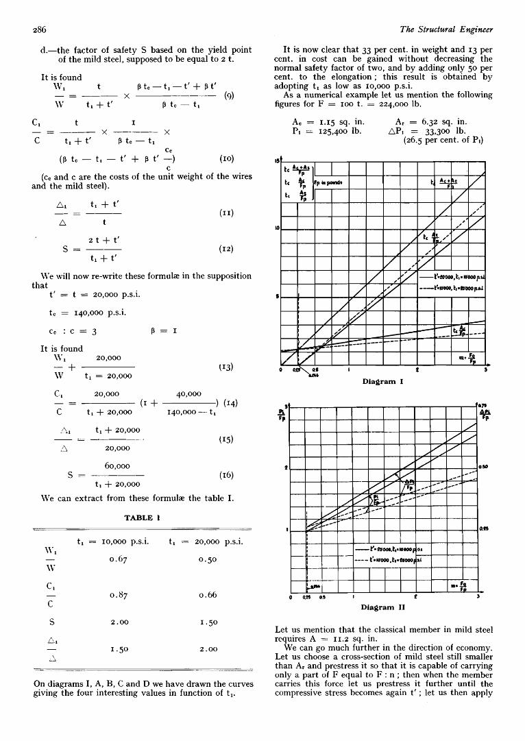
It is now clear that 33 per cent. in weight and 13 per cent. in cost can be gained without decreasing the normal safety factor of two, and by adding only 50 per cent. to the elongation ; this result is obtained by adopting tl as low as 10,000 p.s.i.
As a numerical example let us mention the following figures for F = IOO t. = 224,000 lb.
A, = 1.15 sq. in. A, = 6.32 sq. in. P1 = 125,400 lb. AP1 = 33,300 lb.
(26.5 per cent. of PI)
U'e will now re-write these forrnulze in the supposition that
t' = t = 20,ooo p s i .
tc = 140,000 p.s.i.
cc : c = 3 p = 1
It is found \v , 20,000 - + \v t , = 20,000 'm,
Diagram I
c. 1 20,000 40,000
C t , + 20,000 1~0,000 - t 1
- - _ (1 + ) (14)
A1 t , + 20,000
'!l 20,000
- - - ---
60,000
t , + 20,000
S ---
il.'e can extract from these formulze the table I.
TABLE 1
t, = 10,000 p s i . t l = ZO,OOO p.s.i.
0 .67 0.50
c. 1 - 0.87 C
0.66
S 2 .oo I .50
"1 - I .50 2 .oo
\ 2
On diagrams I, A, B, C and D we have drawn the curves giving the four interesting values in function of tl.
0 Q29 0.5 I f
Diagram I1 3
Let us mention that the classical member in mild steel requires A = I 1.2 sq. in.
We can go much further in the direction of economy. Let us choose a cross-section of mild steel still smaller than A, and prestress it so that it is capable of carrying only a part of F equal to F : n ; then when the member carries this force let us prestress it further until the compressive stress becomes again t' ; let us then apply

November, 1950 287
another F : n so as to create a tensile stress t ; let us then prestress it again and so on.
The relative weight becomes W, t
W - - -
n (tl + t')
io 000
1)'ooo
IODOO
Diagram I11
. t r in a i
LP pd
Diagram IV
The following table gives numerical results obtained by this way of working :
wn c , O n Ac A, S - - -
W C n n = o 0 11.2 2.00 1 .00 1.00 1.00
I 1.15 6 . 2 7 2 . 0 0 0.67 0 . 8 7 1.50 2 1.39 2.30 1 . 5 0 0.33 0.58 1.50 3 I .48 0.98 1.33 0.22 0.49 1.50 4 1.53 0.314 1.25 0.17 0.44 1.50
(This table is made in the supposition that t = t' = 20,000 4 . 7 6 1-55 0 - 0.14 0.42 -
p.s.i. ; t, = 10,000 p s i . ; tc = 140,000 p.s.i.).
This assumes that a fraction F : n of F is the only changeable part in the total load.
We have not mentioned this method in view of its application, as the above table shows that the factor of safety decreases as n increases from n = I onward.
The Effect of the Decrease In Weight In the above elementary theory we have assumed
that the decrease in weight of the tensile member, from W to W, had no effect on the load F to be resisted. But this is not so in practice.
Diagram V
Let us take as example the case where the tensile member is the lower member of a bowstring girder ; let us, also assume that in the classical design the weight of the tensile member is one-third of the weight of the girder ; gaining 33 per cent. in the weight of the tensile member means gaining 11 per cent. in the total weight of the girder.
Let us assume now that in general p per cent. is gained in the weight of the bowstring girder by pre- stressing its lower member ; we have then
P Wp = Wm (I - -)
I O 0
if Wm is the weight of the girder in mild steel and W p the weight of the girder with its prestlessed member.
Let Q be the working load acting on the girder beside its own weight.
The percentage pt gained in the total load to be carried is
Wm Pt = P
Wm + Q

2% The Structwal Enghaeer
This saving in total weight reduces in the same propor- tion the force F to be carried by the prestressed member, and it reduces also the forces to be carried by all the elements of the girder ; consequently all the cross- sections of the elements of the girder can be reduced so that its weight becomes
Pt \ V I P = W, (I - --)
100
This reduction allows a further reduction in cross- sections, so that the weight becomes
W ' p + Q UT'* ---- W p + Q
and again
W " p + Q IVf" p Wft p ----
\ V I P + Q and so on.
Diagram VI1
The following table gives numerical values in the case where
t = t' = 20,000 p.s.i. t, = 10,000 p s i . t c = 140,000 p.s.i.
Q :W=o.25 Q : W = I economy in weight of lower member 33 - 3 33 .3
economy in weight of beam I I . I 11.1 final economy in weight 38.4 20.0 economy in cost of lower member 13.0 13.0
economy in cost of beam 4.3 4.3 final economy in cost 1S.3 8.2
The writer is aware of the fact that the above calcula- tioil is not ,quite correct, as the weight of a girder cannot be exactly reduced in the same proportion as the total load to be carried. But this slight error is compensated by the fact that we neglected other sources of economy ; in a trussed girder, for example, the cable can be raised towards the supports and a shearing force of the con- trary sign of those given by the loads introduced ; this zllows the cross-section of diagonals and vertical ele- ments to be reduced ; in a girder with a solid web the
4
Id k a p.*.i.
Fig.1.-Diagrams corresponding to formulae 13 to 16.
prestressing of the lower member produces tensile stresses in the top member, which allows a reduction in its cross-section.
The conclusion is that a considerable saving in weight and cost can be made by prestressing the tensile member of a bowstring girder ; this saving is the most important when the dead weight of the girder is considerable as compared to the additional load acting on it. This mainly happens for very big spans and light live loads, as for example in the beams covering an aeroplane hangar of 500 ft. span.
i I p i P I
I
47lt
Fundamental Differences between Prestressed Steel and Prestressed Concrete
In a prestressed concrete beam, the stress in the cable varies only by 3 to 4 per cent. when the additional load acts on the beam. This is not true for a prestressed steel girder ; in prestressed steel these variations are three to four times higher ; this is due to the fact that
November, 1950 289
I t is very easy to establish the formuk relative to this problem ; they are
P I = F p + t' A r (17)
the stresss involved in the mild steel A r are about twenty times higher than for concrete, whereas the modulus of the mild steel is only five to six times that of concrete.
' A second difference is that in prestressed concrete, stretching two wires at a time does not mean a loss in average prestress of more than about 4 per cent., this loss being due to the fact that every new pair of wires which is stretched, makes a loss in prestress of those stretched previously. In prestressed steel this effect is much larger and comes to about nine or ten per cent., which must be taken into account in practice.
II U
4
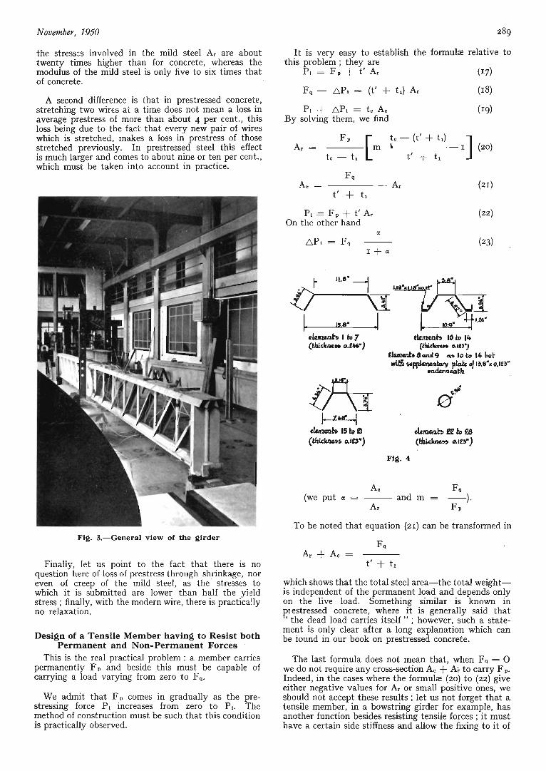
Fig. 3.-General view of the girder
Finally, let us point to the fact that there is no question here of loss of prestress through shrinkage, nor even of creep of the mild steel, as the stresses to which it is submitted are lower than half the yield stress ; finally, with the modern wire, there is practically no relaxation.
Design of a Tensile Member having to Resist both Permanent and Non-Permanent Forces
This is the real practical problem : a member carries permanently FP and beside this must be capable of carrying a load varying from zero to F,.
We admit that F, comes in gradually as the pre- stressing force P1 increases from zero to PI. The method of construction must be such that this condition is practically observed.
P1 + Apt = t e A e By solving them, we find
A e F,
A, F, (we put a = - and m = -).
To be noted that equation (21) can be transformed in
F P
t' + tl A r + Ac =
which shows that the total steel area-the total weight- is independent of the permanent load and depends only on the live load. Something similar is known in prestressed concrete, where it is generally said that " the dead load carries itself " ; however, such a state- ment is only clear after a long explanation which can be tound in our book on prestressed concrete.
The last formula does not mean that, when F, = 0 we do not require any cross-section A, + A r to carry FP. Indeed, in the cases where the formulae (20) to (22) give either negative values for A r or small positive ones, we should not accept these results ; let us not forget that a tensile member, in a bowstring girder for example, has another function besides resisting tensile forces ; it must have a certain side stiffness and allow the fixing to it of

290
the elements making the bridge deck or the platform carried by this girder.
It is easy to compute the formuk for relative weight, cost and elongation :
W, t m
W t ‘ + t, ~ + m
Cl W1 2 t
c W t c - t t ,
Cl t ’
C (I + m) (t’ + tl)
- - - x - (24)
- = - + ( I - -x- :‘3 (25)
or
_ - - z(m + I) t’ + z t,
t c - t,
The Strzlctwal ENgirZeer
I
Fig. 5.-Anchorage of the wires at the end of the girder
AI W, Noted that - is the reverse from - ; to be re-
n W
membered that the A are the elongations due to Fq and not due to FP + F, ; this is because the only thing that matters generally in practice is the deformation due to F,.
We have made diagrams representing formulz (20) to (27) ; on these diagrams I, I1 and I11 we have adopted tc = 140,000 p.s.i. and t = 20,ooo p.s.i. ; two cases of values for t’ and t, have been considered ; they are such that t, + t’ = 30,000 p.s.i. in both cases.
The following conclusions can be drawn from these diagrams :
a.-It is more economical to adopt t, = 10,000 p s i . than 20,000 p.s.i.
b.-In both cases considered the values of W, : W and A, : A are the same.
C.-Ar is zero for m = 0.266. If m is smaller or near to this value the solution given by the diagrams is not acceptable, as already pointed out.
d.-For m = I or more the value of A, : A is accept- able and the economy in weight and cost is considerable ; for example with m = I we gain 67’ per cent. in weight and 45 per cent. in cost.
Fig. 6.-Tlie loading system
Coming back to the conclusion I ‘ c ” we will explain how to solve< the problem in cases where the diagram gives a value of Ar which is not acceptable. In that case a minimum value must be chosen for Ar, taking into account the practical conditions of the problem. It is obvious that having chosen a A, larger than the one given by the diagrams, there will be no need to put it under compression up to the permissible stress t’ ; let us call t’w the stress to be used (working stress).
The formula are then F p + Fq - t1 Ar
t c A, = (28)
PI - F P
Ar t ’w =

November, 1950
Should it be found that the elongation is exaggerated, the problem would have to be re-examined by taking
the acceptable value of -- as data. A1
n The formulas are then
tc-(t'W+tl)
tI2 - t , t'w + tl Ar = -- F~ [m --__-
The effect of F, is to change a compressive stress t' in a tensile stress t, ; the reserve of stress existing then before the yield point is reached is 2 t - t ; this means that to F P + F, a force F must be added equal to
2 t - t f l
t' + t l F = Fq (41)
before the yield point is reached. Hence
or m 2 t - t t ,
~ + m t' + t , s = 1 + - X (43)
In this case we find P, = Fp + t'w A r (36)
z. Q8
7. )+&
Cl t
C ( I + m) ( t ' w + tl) - - -
z(m + I) t', + 2 t l
tc -- t , or
Cl W, 2 t tl W1
C W tc - tl t W - - - -- + ----(I - - -) (40)
The above theory is still incomplete, as it does not take into account the factor of safety.
Safety Factor Let us admit that the mild steel has a yield point of
z t. ; in other words, the safety factor for the member made entirely in mild steel is 2.
Let us compute 'the safety factor of the prestressed member calculated with formulas (20) to (22),
W' 1 t m t(S - I)
W t' + tl I + m 2 t - t l - - - x - - - -~ (44)
If one accepts S = 2 equation (43) becomes
m(2 t - t') - t'
1 + 2 m tl = - - (45)
In other words, if it is desired that the safety factor for the prestressed member be 2, there is a relation between t' and tl. Our diagram IV translates formula (45) in the case where t = 20,ooo p.s.i. Our diagram V gives the value of W, : W for S = 2 and t = 20,ooo p s i . (form. 44).
Let us note that for S = 2 formulas 27 and 43 allow us to write
A1 tl
n t = 2 - -
Practical Solution of the Fundamental Problem We call the fundamental problem, the one where the
value given for Ar and Ac by the diagram I to I11 or the corresponding formulae is acceptable.
The values of F P and F, being given, we know m ; we accept t = 20,ooo p.s.i., and tc = 140,000 p.s.i., we require S = 2. We know that it is advisable to accept a value of t' as high as possible, say t' = 20,ooo p.s.i.
The diagram IV gives t (formula 45) and the formulas (20) to (23) give the solution.
Let us suppose, for example Fp = 100 t. Fq = zoo t. ; hence m = 2
Diagram IV gives tl = 4,000 p.s.i. and the formulas (20) to (23) give
A, = 14.20 sq. in. A, = 4.24 sq. in. P, = 229 t. Pi = 46 t.
Consequently (as A = 33.6 sq. in.)
W1 Cl A1 - - - 0.55 - - - 0.802 - - W
- 1.80 C n
Practical Solution in case the Ar found is not Acceptable
In the case where Ar given by the fundamental theory is not acceptable, we have to choose a value of A r but in this case we can no longer choose t' arbitrarily.

The Structural Engineer
From formulas (28) to (30) is deducted after having replaced
t’n by t’
Taking into account equation (43) written for S = 2, this becomes
This is an equation in tl which gives
(47)
Consequently, our problem is solved as follows : Compute t , from 47 ; t‘ from 46, say
Apply then formulae (28) to (31). We have drawn the diagrams VI and VII, which trans-
Let us take the following example : late the formulas (47) and (48).
F, = 100 t. ; F, = 25 t. ; hence m = 0.25 Let us choose Ar = 3.74 sq. in. Formula (47) gives t = - 7,230 p.s.i. ; and formula (48) t’ = 16,700 P.E.I. Finally, through (28) to (31)
Ac = 2.14 sq. in. P, = 128.3 t. AY, = 9.1 l.
In this case (A = 14 sq. in.) W, Cl A, - = 0.422 - 0.730 W C
=r 2.36 - - - a
Practical Calculation, when A I : A is given
Formulas (32) and (43) combined (with S = 2 ) give together with S = 2
Consequently, the problem is solved as follows :
(34) to (37) by giving to t’r the value found by (50). Compute t’ from (50) and then apply the formulatt
Let us take the following rxample :
F p = IOO t. ; F, = 25 t. Hence m = 0.25. Let us take A, : A = 2.
Formulas (50) and (45) give
From formulas (34) to (37) with t‘, = S,ooo p.s.i., t’ = S,ooo p s i . t , = 0.
we find A, = 5.0 sq. in. A, = 1.95 sq. in. PI = 118.0 t. C X I = 7.0 t.
W1 c. I A,
W c. c\.
In this casc
- - 0.50 - = 0.7s - = 2 2
Results of the Test of a Trussed Girder with a Prestressed Lower Member
Fig. 2 gives the theoretical shape of the girder ; Fig. 3 shows a photo of it ; Fig. 4 gives the cross-section of the different elements.
The lower member has been prestressed by means of a cable of 16 wires of 5 mm. (0.196 in.) having the following cl-macteristics :
Ultimate 248,000 psi. Equivalent yield stress 2z0,ooo p.s.i. Modulus 27,800,000 p.s.i. Elongation on 7 diam. I I .(,:/U
The steel of the trussed girder itself is commercial mild steel with an ultimate strength between 53,000 and 60,000 p.s.i.

November, 1950 293
The beam has been prestressed after the deadweight of 2,210 lb. has been applied. The average stress established in the wires is 92,800 p.s.i., giving a total initial prestressing force of P, = 92,800 x 0.485 = 44,900 lb. = 20.4 t.
The anchorage of the wires at the end of the beam is shown in Fig. 5.
Fig. 6 shows the loading system consisting of a steel girder placed on top of the prestressed girder at the points corresponding to the vertical elements 28 and the symmetrical one ; this loading girder carries a jack on top of which we have placed a hydraulic load measur- ing device giving an accuracy of I per cent.
Strain measurements have been taken by means of electrical strain-gauges numbered I to 34 and placed as shown in Fig. 7.
We have also measured the deflection at midspan and the change in length of the lower member.
For the sake of simplicity we shall only record here the results given by the loading test and compare them with the theoretically computed values.
Let us however first mention the stresses as computed in the system under the separate and combined effect of the dead load and the prestressing ; Table I1 gives these values. We have added to it a column giving the calculated stresses under the load of 2 x I t.
TABLE I1 (Stresses in p.s.i.)
Stress Stress Element under due to Combined 2 x I t
dead load prestressing stresses
Top member I - 285 7 - 855
&;tom 'member 8 o ,I 14 +I,700
Diag. 15 +I8140 Diag. 21 + 142 Vertical 23 -1,280 Deflection +o.ogq in. Shortening of lower
member -
0
0 -12,000 -1g,000
0 0 0
-0.625 in.
+0.320 in. -0.052 in.
One indication of this Table I may seem wrong at first sight, namely, the fact that under 2 x I t. the stress in the end element 8 of the lower member is in com- pression, whereas in an ordinary trussed girder, it would be zero. This is due to the fact that, as the girder deflects, the bottom member elongates and consequently the stress in the cable increases ; this increase for 2 x I t. is 0.543 t.
With the results of Table I, we can now compute the working load of the girder and the load producing the yield stress in the lower member.
We will assume that tl = 10,000 p.s.i., and that the yield point of the mild steel is equal to 2 x 20,ooo = 40,000 p.s.i.
We must also mention that the loading device (jack, girder, etc.), weighs 0.4 t. (896 lb.).
The working load 2 x Pw, giving t, = 10,000 p.s.i., is given by (see in Table I1 stresses in lower member 14).
17,300 + 10,000 = Pw X 5,500. Hence
P, = 5 t. It should be remembered that P is one of two point
The load 2 x P,, producing the yield stress in element loads on the girder and not the total load.
14 can be computed as follows :
Hence 17,300 + 40,000 = Pe X 5,500.
P, 10.40 t.
This means that the calculated safety facto1 is
IO. 40
5 S = - - - 2.08
Under the load 2 x P, = 2 x 10.40 t., the pre- stressing force has become
giving a stress in the wires of 120,ooo p.s.i. The stress in the vertical element 23 is
The stress in the top member 7 is
20.4 + 0.543 x 10.40 = 26.1 t.
-1,280 - 2,630 x 10.40 = -28,700 p.s.i.
-855 - 3,050 x 10.40 = - 32,555 p.s.i.
However, the stresses in these latter compressed elements must be divided by the buckling faqtor and become for vertical element 23
for top member 7 - 28,700 : 0.83 = - 34,600 p.s.i.
- 32,555 : 0.88 = - 36,800 p.s.i.
These figures show that under a load of z x 10.40 t. the bottom member, the first vertical element :and the top member are all under stresses very near to the yield stress. If we learn now that we have taken no account in these calculations of the possibility of the top member buckling as a whole, it is understood that the girder will fail owing to this latter cause.
Table I11 gives a summary of the calculated stresses.
TABLE I11 --
Prestr. + dead W. Prestr. +dead W. + 2 x 5 t. + 2 x 10.40 t.
Top member Lower member Vertical Diagonal API in % Cable stress Deflections in in
~
NOTE. Stresses are in p.s.i. ; compressive stresses are increased by buckling factor.

294 The Structural Emgineer
We are now going to make a comparison between the measured strains and deflections and the calculated ones. In transforming the strains measured into stresses, we have used for mild steel a modulus of 29,000,000 p.s.i.
In Table IV we compare the values obtained during the variation of P from zero to 6 t.
b.-The greatest difference is for the vertical element No. 23, which carries less than the calculation shows. This is probably due to the stiffness of the joints which, in the calculation, are supposed to be frictionless pin joints.
c.-The lower member No. 14 carries about 13 per cent. less than calculated ; this is probably due to the fact that the construction joint at the middle of the span is a bolted joint.
11.-For P varying from zero to 8.5 t. a - b - c as above. d.-In the top member No. 7 some strain-gauges have
given strains above the elastic limit ; notwith- standing this we have multiplied them by the value of E corresponding to the elastic state ; but this gives fictitious stresses, which are far above the real ones ; this is the reason why the average stress in this element is 15 per cent. higher than the calculated one.
111.-In general it may be noted that the stresses are far from uniform in the cross-section of the different elements even in the middle of these elements, where the bending moment must be very small.
In view of illustrating this, we have prepared Figs. 8, g and IO giving for different loads the stress distribution in the cross-section of elements 7, 14 and 15.
TABLE V * (P f r o m 0 to 8.5 t.)
Fig. 11.-Central part of beam after failure by buckling
TABLE IV (P f r o m 0 to 6 t.)
Stresses
Calculated Measured
Strain- gauge
Stresses
Calculated Measured
Top member No. I
- 2,560
- 2,560 - 3;130 Top member
2 No. I I
3
4 Lower member 5
No. 8 6
I 2 3
4
6 5
7 8 9 IO I1
I2
I3 I4 ' I5 16 '7 18 19 20 21 22
23 24 25 26
average - 2,750
- 2,000 - 2,000 - 2,000
13,900 + 13,900 +I3,900 +I3,900 +I3,900
-1 5,800 -15,800 -15,800 -15,800 -1 8,100 -18,100 -18,100 -18,100 -18,100 -18,100 -18,100 -18.100
-18, IOO -18,100
-18, IOO
Lower member No. 8
Diagonal No. 15
7 Diagonal No. 15 + 12,800 average
+17,200 Average
Average -16,200
Average -29,700
I 11 IO
-22,400 -22,400 -22,400 -22,400
--12,800 -12,400 -11,100
- 9,800 -1 I, IO0
-15,300 -18,900 -21,100 -20,800 -20,700 -20,000 -19,300 -17,000
- 7,250 -12,600
I2 Vertical No. 23
I3
I5 I4
Vertical No. 23
average -1 I, goo
average -17,500
-IO, 800 -34,600 -67,000 -61,800
-32,500
-26,600 -20,500 -12, IO0 - 2,000
-
-
16 I7 18 I9 20 21 22
Top member No. 7
23 24 25 26
Top member No. 7
,Lower member No. 14
+32,800 +32,800 +32,800
average i- 27,300
+ 46,600 + 46.600 + 46,600 Lower member I 28 27
+ 39,800 Average No. 14 I 29
, , Diagonal , No. 21
average .O Diagonal
No.' 21
30 0 0 0 0 0
In Table V the comparison is made for the variation
These results suggest the following remarks :
a.-As a whole the measured stresses are fairly close
of P from zero to 8.5 t.
1.-For P varying from zero to 6 t.
to the calculated ones.
Fig. 8 shows clearly that the yield point is reached ai the point occupied by the strain-gauge No. 18 for the load of 2 x 7 t. ; this was the beginning of the failure of the beam by the buckling of the top member as 'a whole.

November, 7950 295
The maximum load reached was 2 x 8.5 t. This failure has nothing to do with the prestressed lower member in which the yield stress would have been reached according to calculations under a load of z X 10.40 t.
It should be noted that for the load of 2 x 7 t. the calculated stress in the element No. 7 is (see Table 11).
- 853 - 7.2 x 3,050 = - 22,855 p.s.i. or, taking the buckling into account over the length of one panel
which is far below the yield stress. But the fai1ul.e occurred not by this stress being too high, but by the buckling of the top member over its total length.
We intend to repeat the test on a similar beam, in which the general buckling will be avoided by side guiding.
Fig. 11 gives a photo of the central part of the beam after failure by buckling.
Let us finally mention the following results in inches :
- 22,855 : 0.88 = - 26,000 p.s.i.
2 x 6 t . 2 x 8.5 t. Calc. Meas. Calc. Meas.
Deflect ion 1.69 2.00 2.38 3.58 Elongation of cable 0.31 0.32 0.44 0.51
The differences between the measured and calculated values are due to the bolted joint as already explained, and for the load of z x 8.5 t. at the same time to the fact that the yield stress is reached in the top member.
Practical Example Fig. 12 gives the general cross-section of an aeroplane
hangar made in prestressed structural steel. It has a span of 500 ft. and the beams-8 ft. apart-have only a depth of 15 ft. It is the most economical structure in the present state of engineering.
Fig. 12
Other Ideas on Prestressed Structural Steel The idea of prestressing steel has been considered
during the last few months. The most interesting paper on it was published in Germany by Dr. Ing. F. Dis- chinger, Professor at the Technical University of Berlin, at the end of last year (Der Bauingenieur, Heft rr and 12 ; 1949). - He discusses the method proposed by us and concludes that the saving it can give is moderate. We do not agree with his arguments, which are twofold :
a.-By replacing part of the lower flange of a mild steel girder by high tensile steel, the girder is weakened and the stresses in it due to the live load increase. This obviously is an incomplete view.
b.-The tensile force developed by the live load in the lower flange, is very different from the compressive force developed in the top flange. This is true, but what does it matter ? What does it mean in relation to the cost of the girder ? It may well be that Dr. Dischinger is correct in stating that his method of having the concrete road slab working together with the main steel girders of a bridge, gives a larger saving than our
proposal to prestress the lower member of the girders, but this is another problem. I t shows only that the greatest saving would be reached by applying both methods simultaneously.
What Dr. Ing. Dischinger proposes is to consider steel girders with a concrete slab solidly attached to their top flange, the whole of this compound structure being then prestressed by any of several means he suggests.
In his idea the concrete incorporated is nothing else but the concrete slab used as support of the road or the railway tracks of a steel bridge. This concrete slab exists in any case in a steel bridge, but up to the present it has never been taken into account as working together with the main steel girders.
He first explains that the concrete slab cannot be relied upon as working together with the steel girder, unless it be sure that it is not cracked by shrinkage or by the negative moments existing above the internal supports, if the beam is a continuous one over more than two supports. Hence his first requirement is that the slab should be prestressed to such an extent that it never cracks due to loads or to shrinkage. This is the limited scope of the prestressing proposed by him.
The slab can be prestressed in several ways ; for example :
a.-by casting it on top of the steel girder, whilst this girder is still supported by formwork underneath. If this formwork is removed after the concrete has hardened, the slab will be prestressed ; however, this prestress is maximum at midspan and zero at the ends, if the girder is simply supported, consequently the result is not perfect.
b.-By casting the slab on top of the beam, and then- in case of a continuous beam-by lowering slightly all the supports except the extreme ones. This has the disadvantage of prestressing the slab as well above the supports, as at the middle of the spans ; consequently a smaller compressive stress remains available at midspan for the live- load.
The system which Dr. Ing. Dischinger recommends is to cast the slab above the steel girder, but on a steel- plate, which is kept at a distance from the top flange of the steel girder by round transverse rods or rollers, allowing a free longitudinal movement. When the slab has hardened, he prestresses it by cables attached to its ends ; when this prestressing is done, he fixes with rivets the steel plate on which the slab has been cast to the top flange of the girder. He can then remove the prestressing cables or not, and place cement mortar in the gap kept open by the round rods.
In large continuous beams, he does not only use a concrete slab on top of the girder, but provides one underneath the bottom flange near the supports, so as to increase the moment of inertia of the cross-section.
Here we must leave this description of principles. The general conclusion is that the idea of prestressing steel structures is gaining ground and is bound to de- velop.
The specialists in structural steel have the great advantage of having at their disposal proper means of prestressing. The girder tested in our laboratory has been prestressed with the same sandwich cable, which we are using for prestressed concrete and with the same jacks. This fortunate fact will allow prestressed steel to make much quicker progress than has been possible in prestressed concrete.