Embed Size (px)
Citation preview
Prestressed Spliced 1-Girders: Tenth Street Viaduct Project, Lincoln, Nebraska
Joseph A. Ficenec, P.E. Structural Project Engineer
Wells Engineers, Inc. Omaha, Nebraska
Steven D. Kneip, P.E. Vice President, Project Manager Wells Engineers, Inc. Omaha, Nebraska
Maher K. Tadros Ph.D., P.E.
38
Cheryl W. Prewett Professor of Civil Engineering and Director,
Center for Infrastructure Research University of Nebraska at Lincoln
Omaha, Nebraska
Larry G. Fischer, P.E. Vice President Concrete Industries, Inc. Lincoln, Nebraska
The Tenth Street viaduct project in Lincoln, Nebraska, showcases two unique bridge structures. The first is a pedestrian/bicycle overpass which features spliced, prestressed concrete /-girders, designed and built using a new continuity technique. This structure incorporates level landings for the disabled and a deck heating system. The second structure is a vehicular viaduct. Design of this structure included alternative superstructures - a continuous, composite steel plate girder, and a composite, spliced concrete prestressed girder system made continuous via full-length post-tensioning. This paper presents the various project phases, with an emphasis on the pedestrian/bicycle overpass and the implementation of the new girder continuity technology.
PCI JOURNAL
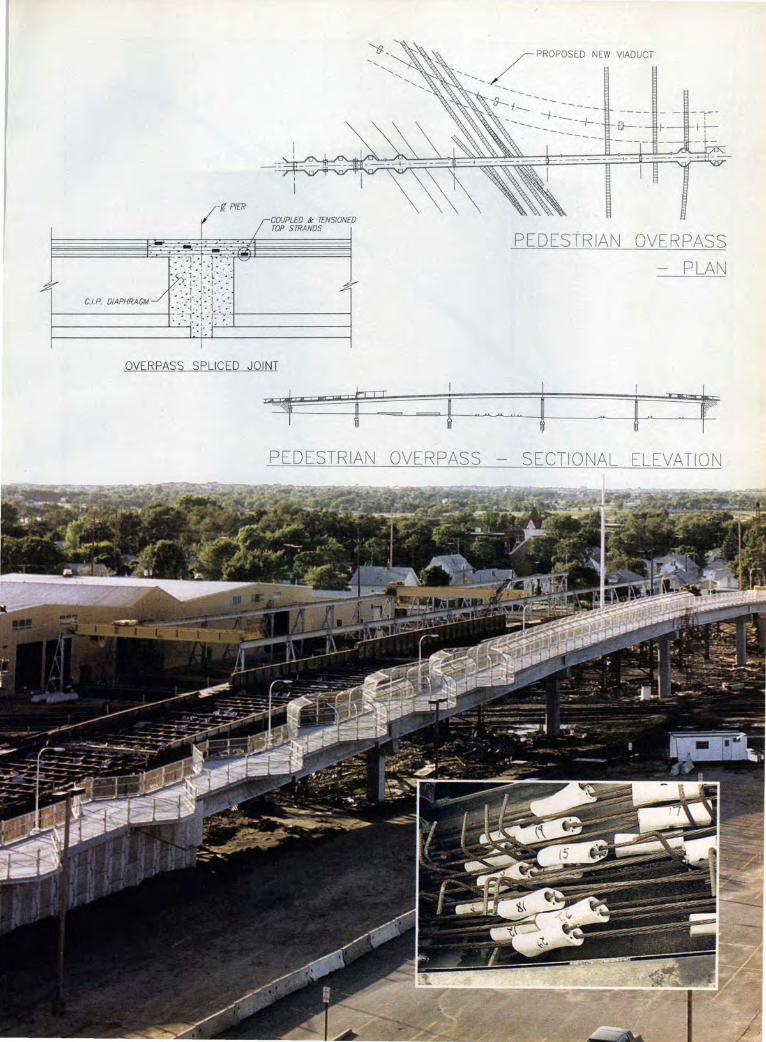
i PIER
COUPLED & TENSIONED TOP STRANDS
OVERPASS SPLICED JOINT
r
'-,,/PROPOSED NEW VIADUCT
-/3--._ -----~--- -----
--- --!-----+------ ----
PEDESTRIAN OVERPASS
- PLAN
j PEDESTRIAN OVERPASS - SECTIONAL ELEVATION
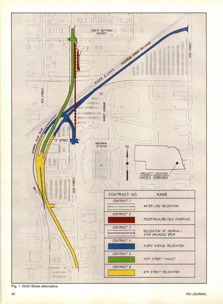
Fig. 1. Ninth Street alternative.
40
~ ..
CON7'RACT 1
..._ (
.. ) . J I
.• . ....... - . ., ................ -.......
- · PROJECT LOCA noN LINCOLN, NEBRASKA
! .. -. .................. ..
... ........ '
NAM E
E--_:_---=j WA7rR LINE RELOCAnoN
CONTRACT 2
CONTRACTS
PEDESTRIAN/BICYCLE OVERPASS
RELOCA noN OF JOURNALSTAR RAILROAD SPUR
A VE'RY A VENUE RELOCA noN
1077-1 STREET VIADUCT
9TH STREET RELOCA noN
PCI JOURNAL
The existing Tenth Street viaduct was a highly visible structure, located on the University of Ne
braska at Lincoln (UNL) campus directly adjacent to Memorial Stadium - home of the Nebraska Cornhuskers' football team. This viaduct was the only elevated crossing on local streets over the Burlington Northern Railroad (BNRR) and the Union Pacific Railroad (UPRR) for 2.3 miles (3.7 km). It served as the primary access between the North Bottoms residential district and both the University of Nebraska campus and the Lincoln central business district.
The City of Lincoln, Public Works Engineering Division, determined that the existing Tenth Street viaduct and its attached pedestrian walkway bad exceeded its useful life. It had become a safety hazard to vehicular, pedestrian and rail traffic. The viaduct had a sufficiency rating of 5.7 out of 100 and was posted for a 10 ton (9.07 t) limit. Fire trucks and local trucking companies were not permitted to use the viaduct, resulting in excessive inconvenience and increased danger to adjacent neighborhoods and businesses.
The Public Works Engineering Division developed various alternatives for the replacement of the Tenth Street viaduct, including a Tenth Street viaduct alternative (replacement at its present location), a "split" viaduct alternative (separate structures on Ninth and Tenth Street), and a Ninth Street viaduct alternative. Each of these alternatives was consistent with Lincoln's long-range comprehensive plan (which included a tie-in to the future Holdrege Street Bypass) and with UNL's preliminary master plan. After an environmental assessment document was developed and a public hearing held, the Public Works Engineering Division selected the Ninth Street alternative (see Fig. 1).
PROJECT DEVELOPMENT
Due to the high visibility and importance of the proposed Tenth Street viaduct, the Public Works Engineering Division established several criteria for the construction of the new viaduct:
September-October 1993
• The new viaduct, pedestrian/bicycle overpass and all roadways had to be open to traffic by September 1, 1993 (prior to the first Cornhusker home football game).
• Pedestrian traffic to and from the North Bottoms District had to be maintained at all times. Hence, the existing viaduct had to remain in service until the new pedestrian/ bicycle overpass was open.
• The intent of the Americans with Disabilities Act (ADA) of 1990 had to be met; that is, safe and comfortable passage for all pedestrians had to be provided. To accomplish these criteria, the
City of Lincoln selected the team of Wells Engineers, Inc. (WEI), Omaha, Nebraska, and HWS Engineers, Inc., and Noel Engineering, both of Lincoln, Nebraska, in December 1991. WEI, as prime consultant, provided project management, structure concepts and designs , and traffic control and signal design. HWS Engineers, Inc., provided surveys, soils investigations, and rightof-way utility relocation and roadway designs, and Noel Engineering provided electrical and lighting design.
In order to satisfy the ambitious completion schedule and to maintain pedestrian traffic and rail service, the project team developed a design and construction phasing plan consistent with available funding sources. The Federal Highway Administration (FHW A) funded phases of the project related only to the Tenth Street viaduct and pedestrian overpass structures, thus requiring these phases to be administered and bid by the Nebraska Department of Roads (NDOR). The remaining phases were administered and bid separately by the City of Lincoln. The six-phase plan (see Fig. 1) developed by the project team was:
Phase I: Design and relocate a watermain parallel to Tenth Street.
Phase II: Design and construct the new pedestrian/bicycle overpass structure directly adjacent to the existing Tenth Street viaduct. A temporary mechanically stabilized earth (MSE) wall was required at the north approach which became integral with the north approach to the new viaduct.
Phase III: Design and relocate the Journal-Star spur track.
Phase IV: Design and construct the A very A venue relocation and associated utilities from V Street to 14th Street.
Phase V: Design and construct the new Tenth Street viaduct and approaches.
Phase VI: Design and construct Ninth Street from Tenth Street to the A very A venue relocation, including associated utilities.
Due to overlaps in construction schedules of the various phases, there was the potential of having four contractors working in the project area at one time. Detailed traffic control and construction phasing plans were required to ensure that construction proceeded as scheduled and that impacts to rail, pedestrian and vehicular traffic were kept to a minimum.
Because of the complexity of this project, the extensive number of agencies involved and the large number of property owners affected by this project (i.e., FHW A, NDOR, City of Lincoln, BNRR, UPRR, Chicago and Northwestern Railroad, UNL, Lincoln Electric System, Lincoln Telephone and Telegraph, Minnegasco), coordination was critical. Weekly design meetings and monthly progress meetings were held to address design, construction and political issues, and to ensure the satisfactory and timely progression - and ultimate completion - of the project.
Aesthetics
Due to the project's close proximity to the UNL campus and the North Bottoms District, aesthetics was an issue. Wells Engineers, Inc., developed consistent aesthetic concepts, including pier configurations and MSE wall treatments , for both the pedestrian/bicycle overpass and Tenth Street viaduct structures. These concepts were presented to the City of Lincoln's Public Works Engineering Division for its input and selection before being presented to the City 's Urban Development Group for final approval (see Figs. 2a and 2b).
PHASE IIDESIGN OF THE
PEDESTRIAN/BICYCLE OVERPASS
In conformance with contractual requirements, WEI developed a bridge
41
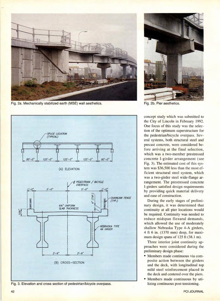
Fig. 2a. Mechanically stabilized earth (MSE) wall aesthetics.
1'-0" 5'-0"
125'-o" I 90'-o·l (A) ELEVATION
g PEDESTRIAN / BICYCLE OVERPASS
5'-0"
CHAINUNK FENCE (rrP.)
NEBRASKA TYPE 4A GIRDER
J'-9" J '-9"
(B) CROSS-SECTION
Fig. 3. Elevation and cross section of pedestrian/bicycle overpass.
42
Fig. 2b. Pier aesthetics.
concept study which was submitted to the City of Lincoln in February 1992. One focus of this study was the selection of the optimum superstructure for the pedestrian/bicycle overpass. Several systems, both structural steel and precast concrete, were considered before arriving at the final selection, which was a two-member prestressed concrete !-girder arrangement (see Fig. 3). The estimated cost of this system was $36,500 less than the most efficient structural steel system, which was a two-girder steel wide-flange arrangement. The prestressed concrete !-girders satisfied design requirements by providing quick material delivery and ease of construction.
During the early stages of preliminary design, it was determined that continuity at all pier locations would be required. Continuity -was needed to reduce midspan flexural demands , which allowed the use of moderately shallow Nebraska Type 4-A girders , 4 ft 6 in. (1370 mm) deep, for maximum design spans of 125ft (38.1 m).
Three interior joint continuity approaches were considered during the preliminary design phase: • Members made continuous via com
posite action between the girders and the deck, with longitudinal top mild steel reinforcement placed in the deck and centered over the piers.
• Members made continuous by utilizing continuous post-tensioning.
PCI JOURNAL
• Members made continuous by splicing and pretensioning strand extensions at adjacent ends. The first system was discounted due
to its lack of continuity under all loads except live load and its lack of precompression in the pier diaphragm concrete. While the second system offered continuity under all loads except self-weight and offered precompression of pier diaphragm concrete, its use was not seriously contemplated because the structure lacked the posttensioning volume necessary to render its use cost-effective.
Consultation relative to the implementation of the third system commenced and proceeded in meetings involving personnel from WEI, UNL and Concrete Industries, Inc. This blend of design, research and production talent was an invaluable asset in terms of both the overall and the specific prestressed splicing requirements for the structure, particularly during the preliminary design phase.
A preliminary design was submitted to the City of Lincoln and the Nebraska Department of Roads (NDOR) in March 1992 which recommended the use of the third system, whereby girder members would be made continuous at pier supports by coupling and tensioning strand extensions. This submittal was subsequently approved by NDOR and final design commenced on the pedestrian/bicycle overpass structure.
During the final design, WEI addressed many design and constructibility issues relative to the spliced girders, including: • The most efficient strand profile and
the easiest way to achieve it • The availability of splicing hard
ware and how to accommodate its placement
• The need for a specialty contractor to do all strand splicing and tensioning The solution to the first item became
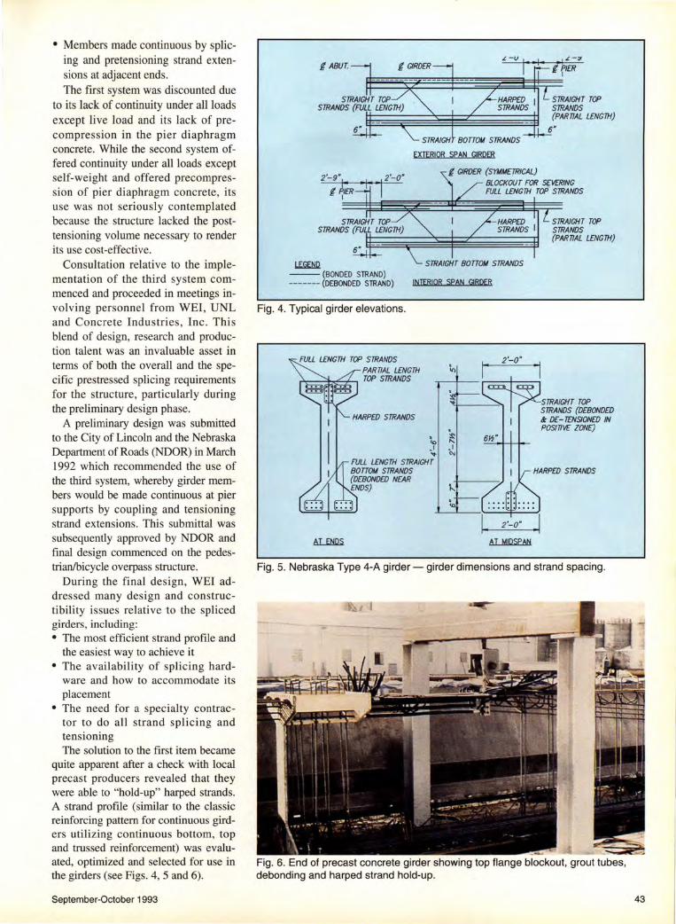
quite apparent after a check with local precast producers revealed that they were able to "hold-up" harped strands. A strand profile (similar to the classic reinforcing pattern for continuous girders utilizing continuous bottom, top and trussed reinforcement) was evaluated, optimized and selected for use in the girders (see Figs. 4, 5 and 6).
September-October 1993
i ABUT. rJ L -::~
lf1ER
~~~~~~
L.EW!Q. --(BONDED STRAND) -------(DEBONDED STRAND)
Fig. 4. Typical girder elevations.
EXTERIOR SPAN GIRDER
f GIRDER {SY!tiME.TRICAL}
STRAIGHT TOP STRANDS (PARTIAL LENGTH)
BLOCKOUT FOR SEVERING FULL LENGTH TOP STRANDS
INTERIOR SPAN GIRDER
. ~ ~
I _I ;,. <-.
2·-o·
STRAIGHT TOP STRANDS (PARTIAL LENGTH}
STRAIGHT TOP STRANDS {DEBONDED .t DE- TENSIONED IN POSITIVE ZONE}
FULL LENGTH STRAIGHT BOTTOM STRANDS (D£80NDED NEAR ENDS}
AT MIDSPAN
Fig. 5. Nebraska Type 4-A girder- girder dimensions and strand spacing.
Fig. 6. End of precast concrete girder showing top flange blockout, grout tubes, debonding and harped strand hold-up.
43

LONGITUQINAL SECTION A) SWAGED SPLICE WITH TURNBUCKLE
VIEW A-A A ,l--l _ _,_4·-~l.l----'4'--• ---4l
'\: W MINIMUM
LONGITUQINAL SECTION B) SWAGED SPLICE WITH THREADED RODS, PLATES, & LOAD INDICATOR WASHERS
Fig. 7. Strand splices (zero anchorage seating loss type) with slack-recovery hardware.
Fig. 8. Half-hexagon, cantilevered level landing.
Fig. 9. Stephanie and Roger Figard test the ramp section's level landing.
44
Two minor details then required attention . The quantity of bottom strands near member ends was excessive (i.e., temporary top fiber tensile stresses at release were too high) and the top strands near midspan tended to offset the service stress advantages afforded by the bottom strands. To eliminate these problems, strand debonding was utilized. A portion of the full-length bottom strands was debonded, for a short distance, near the member ends.
Also, all full-length top strands were debonded and detensioned in regions of high positive moment. This detensioning was done by sheathing top strands over their debonded length and severing strands near midspan via access blackouts provided in girder top flanges.
The second item, relative to girder splicing, required investigating the availability of splices, determining how they behaved, and selecting "end of girder detailing" to universally accommodate the various strand splices.
After consultation with three suppliers, two items became apparent. First, a 2ft (610 mm) long top flange cope at all strand splicing locations would be required to accommodate the staggered placement of the splices (see Fig. 6). Second, it was determined that the splices could be one of two types - a zero anchorage seating loss splice or a seating loss splice.
Since the seating loss type splices, utilizing chucks, were quite variable relative to their degree of loss, universal detailing to accommodate this type of connector was impossible. Therefore, details were presented based on the use of zero anchorage seating loss type connectors and, by notes and criteria set forth in the specification, the use of the other type was allowed provided all necessary design criteria could be met. See Fig. 7 for two possible zero seating loss type strand arrangements featuring different slackrecovery hardware.
The third item addressed during final design , relative to girder splicing, was the need for a specialty contractor to perform all strand splicing and tensioning. A meeting was held with personnel from NDOR, UNL and WEI to discuss this need. It was mutually de-
PCI JOURNAL

Fig. 10. Pre-bid test specimen.
cided that this portion of the project would be best served by a specialty contractor, particularly since this system was a first-of-its-kind endeavor.
One other design issue, unrelated to the spliced girder system, was addressed during final design . Level landings, 5 x 5 ft (1520 x 1520 mm) in plan, were required at 40 ft (12.2 m) horizontal intervals to satisfy the intent of ADA requirements in ramp areas (i.e. , in areas where the instantaneous grade exceeded 5 percent). A 40 ft (12.2 m) length was required to satisfy ADA's requirement that rest areas be provided in all ramp areas such that the vertical fall between adjacent areas not exceed 30 in. (762 mm).
Because of AASHTO's guidelines for bicycle facilities, placement of the level landings within the bicycle pathway was not feasible ; it would not only impede bicycle movement, but, more importantly, it would not provide the disabled with a safe resting area. After consultation with FHWA' s local bridge engineer and the city engineer, it was determined that the best design solution would be to cantilever halfhexagon deck elements beyond gutter lines (see Fig. 8). This placement removed the landing areas from the main pathway (gutter line to gutter line).
Access to and from the level landings was proposed to be over-warped deck transition zones with instantaneous grades no greater than 8 per-
September-October 1993
Fig. 11. Deck heating system on approaches.
Fig. 12. Center stressing connector used for coupling and tensioning strands.
cent. To test the acceptability of this design for use by disabled persons in wheelchairs, WEI built a custom, fullscale representative ramp section with an attached level landing. This section was then tested by the city engineer's
daughter (see Fig. 9), who is disabled and uses a wheelchair. The design easily passed her test and was subsequently approved for use by the City of Lincoln and FHW A.
Final design of this pedestrian/ bicycle structure was completed by WEI in July 1992. Prior to bid opening, full-scale testing of the girder splice was performed (see "A New Technique to Create Continuity in Prestressed Concrete Members," in this issue). WEI, along with faculty members from UNL, initiated this test with the hope that it would provide a basis for splice evaluation and improvement and would demonstrate the splice's constructibility to local bidding contractors . The test was performed at
Fig. 13. Pier joint with bottom strut cast prior to joint splicing operation .
45
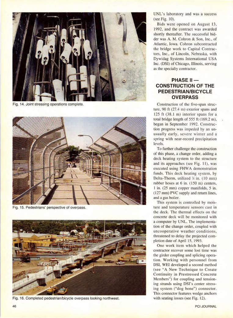
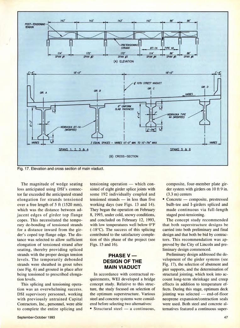
Fig. 14. Joint stressing operations complete.
Fig. 15. Pedestrians' perspective of overpass.
Fig. 16. Completed pedestrian/bicycle overpass looking northwest.
46
UNL' s laboratory and was a success (see Fig. 10).
Bids were opened on August 13, 1992, and the contract was awarded shortly thereafter. The successful bidder was A. M. Cohron & Son, Inc. , of Atlantic, Iowa. Cohron subcontracted the bridge work to Capital Contractors, Inc., of Lincoln, Nebraska, with Dywidag Systems International USA Inc. (DSI) of Chicago, illinois, serving as the specialty contractor.
PHASE II CONSTRUCTION OF THE PEDESTRIAN/BICYCLE
OVERPASS Construction of the five-span struc
ture, 90ft (27.4 m) exterior spans and 125 ft (38 .1 m) interior spans for a total bridge length of 555ft (169.2 m) , began in September 1992. Construction progress was impeded by an unusually early, severe winter and a spring with near-record precipitation levels.
To further challenge the construction of this phase, a change order, adding a deck heating system to the structure and its approaches (see Fig. 11), was executed using FHW A demonstration funds . This deck heating system, by Delta-Therm, utilized Ys in. ( 10 mm) rubber hoses at 6 in. (150 m) centers, 1 in. (25 mm) copper manifolds, 5 in. (127 mm) PVC supply and return lines, and a gas boiler.
This system is controlled by moisture and temperature sensors cas t in the deck. The thermal effects on the concrete deck will be monitored with a computer by UNL. The implementation of the change order, coupled with uncooperative weather conditions, threatened to delay the projected completion date of April15, 1993.
One work item which helped the contractor recover some lost time was the girder coupling and splicing operation. Working with personnel from DSI, WEI developed a second method (see "A New Technique to Create Continuity in Prestressed Concrete Members") for coupling and tensioning strands using DSI' s center stressing system ("dog bone") connector. This connector features wedge anchors with seating losses (see Fig. 12).
PCI JOURNAL
POST-TtNSIONING TfNOON
18'-0"
NEBRASKA BT-IA {IIOOIFIED)
14J'
172' SPAN /2
GIR. 8
14J' 14J'
SPAN /J • • SPAN /4
(A) ELEVATION
VI I lOTH STRffT VIADUCT
GIR. C
I I
8" UNIFORII SLAB THICKNESS
I I
I
SPANS 2 3 & 4
(B) CROSS-SECTION
Fig. 17. Elevation and cross section of main viaduct.
The magnitude of wedge seating loss anticipated using DSI' s connector far exceeded the anticipated strand elongation for strands tensioned over a free length of 5 ft (1520 mm), which was the distance between adjacent edges of girder top flange copes. This necessitated the temporary de-bonding of tensioned strands for a distance inward from the girder's coped top flange edge. The distance was selected to allow sufficient elongation of tensioned strand after seati ng , thereby providing spliced strands with the proper design tension level s. The temporarily debonded strands were sheathed in grout tubes (see Fig. 6) and grouted in place after being tensioned to prescribed elongation levels.
This splicing and tensioning operation was an overwhelming success. DSI supervisory personnel, working with previously untrained Capital Contractors, Inc., personnel, were able to complete the entire splicing and
September-October 1993
tensioning operation - which consisted of eight girder splice joints with some 192 individually coupled and tensioned strands - in less than five working days (see Figs. 13 and 14). They began the operation on February 8, 1993, under cold, snowy conditions, and concluded on February 12, 1993, with low temperatures well below 0°F ( -l8°C). The success of this splicing contributed to the satisfactory completion of this phase of the project (see Figs. 15 and 16).
PHASE VDESIGN OF THE MAIN VIADUCT
In accordance with contractual requirements, WEI developed a bridge concept study. Relative to this structure, the study focused on selection of the optimum superstructure. Various steel and concrete systems were considered before selecting two alternatives: • Structural steel - a continuous,
18'-0"
VARIES
NEBRASKA TYPE 4A (IIODIFIEO)
SPANS 5 & 6
VARIES
composite, four-member plate girder system with girders on 10 ft 9 in. (3.3 m) centers
• Concrete - composite, prestressed bulb-tee and I-girders spliced and made continuous via full-length staged post-tensioning. The concept study recommended
that both superstructure designs be carried into both preliminary and final design and that both be bid by contractors. This recommendation was approved by the City of Lincoln and preliminary design commenced.
Preliminary design addressed the development of the girder systems (see Fig. 17), the selection of abutment and pier supports, and the determination of structural jointing, which took into account long-term shrinkage and creep effects in addition to temperature effects. During this stage, optimum deck jointing was selected - end-of-floor neoprene expansion/contraction seals were used. Both steel and concrete alternatives featured a continuous super-
47
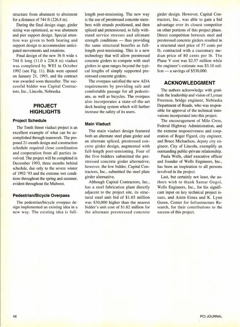
structure from abutment to abutment for a distance of 744ft (226.8 m).
During the final design stage, girder sizing was optimized, as was abutment and pier support design. Special attention was given to both bearing and support design to accommodate anticipated movements and rotations.
Final design of the new 36 ft wide x 744 ft long (11.0 x 226.8 m) viaduct was completed by WEI in October 1992 (see Fig. 11). Bids were opened on January 21, 1993, and the contract was awarded soon thereafter. The successful bidder was Capital Contractors, Inc., Lincoln, Nebraska.
PROJECT HIGHLIGHTS
Project Schedule
The Tenth Street viaduct project is an excellent example of what can be accomplished through teamwork. The proposed 21 -month design and construction schedule required close coordination and cooperation from all parties involved. The project will be completed in December 1993, three months behind schedule, due only to the severe winter of 1992-'93 and the extreme wet conditions throughout the spring and summer, evident throughout the Midwest.
Pedestrian/Bicycle Overpass
The pedestrian/bicycle overpass design implemented an existing idea in a new way. The existing idea is full-
48
length post-tensioning. The new way is the use of prestressed concrete members with strands positioned, and then spliced and pretensioned, to fully withstand service stresses and ultimate strength conditions - thus providing the same structural benefits as fulllength post-tensioning. This is a new technology that will allow prestressed concrete girders to compete with steel girders in span ranges beyond the typical lengths of simply supported prestressed concrete girders.
The overpass satisfied the new ADA requirements by providing safe and comfortable passage for all pedestrians, as well as bicycles. The overpass also incorporates a state-of-the-art deck heating system which will further increase the safety of its users.
Main Viaduct
The main viaduct design featured both an alternate steel plate girder and an alternate spliced, prestressed concrete girder design, augmented with full-length post-tensioning. Four of the five bidders submitted the prestressed concrete girder alternative; however, the low bidder, Capital Contractors, Inc., submitted the steel plate girder alternative.
Although Capital Contractors, Inc., has a steel fabrication plant directly adjacent to the project site, its structural steel unit bid of $1.65 million was $30,000 higher than the nearest bidder's unit cost of $1.62 million for the alternate prestressed concrete
girder design. However, Capital Contractors, Inc., was able to gain a bid advantage over its closest competitor on other portions of this project phase. Direct competition between steel and prestressed concrete girders resulted in a structural steel price of 57 cents per lb, contracted with a customary median price of 80 cents per lb. The Phase V cost was $2.57 million while the engineer's estimate was $3.10 million- a savings of $530,000.
ACKNOWLEDGMENT The authors acknowledge with grati
tude the leadership and vision of Lyman Freemon, bridge engineer, Nebraska Department of Roads, who was responsible for approval of the technical innovations incorporated into this project.
The encouragement of Milo Cress, Federal Highway Administration, and the extreme responsiveness and cooperation of Roger Figard, city engineer, and Bruce Michaelson, deputy city engineer, City of Lincoln, exemplify an outstanding public-private relationship.
Paula Wells, chief executive officer and founder of Wells Engineers, Inc., has been an inspiration to all persons involved in the project.
Last, but certainly not least, the authors wish to thank Samar Gogoi, Wells Engineers, Inc., for his significant input on key technical project issues, and Amin Einea and K. Lynn Geren, Center for Infrastructure Research, for their contributions to the success of this project.
PCI JOURNAL