Embed Size (px)
Citation preview
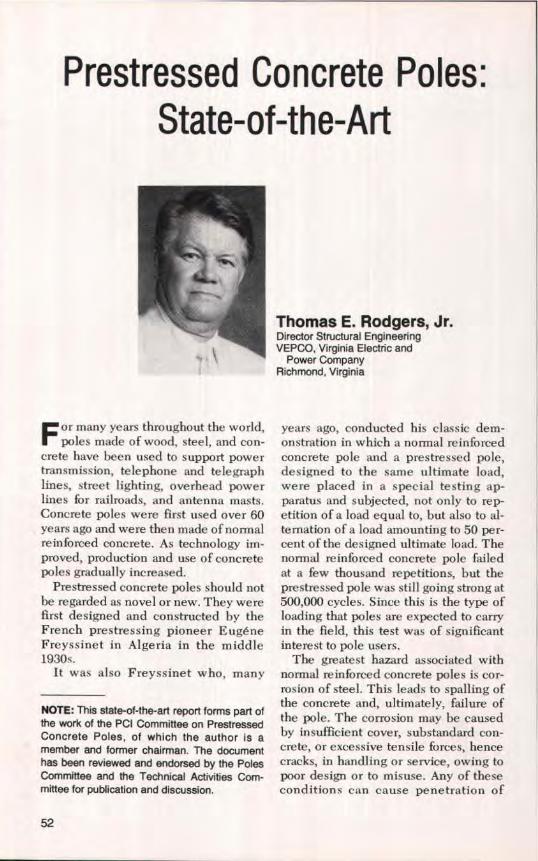
Prestressed Concrete Poles:State-of-the-Art
Thomas E. Rodgers, Jr.Director Structural EngineeringVEPCO, Virginia Electric and
Power CompanyRichmond, Virginia
F or many years throughout the world,poles made of wood, steel, and con-
crete have been used to support powertransmission, telephone and telegraphlines, street lighting, overhead powerlines for railroads, and antenna masts,Concrete poles were first used over 60years ago and were then made of normalreinforced concrete. As technology im-proved, production and use of concretepoles gradually increased.
Prestressed concrete poles should notbe regarded as novel or new. They werefirst designed and constructed by theFrench prestressing pioneer EugeneFreyssinet in Algeria in the middle1930s.
It was also Freyssinet who, many
NOTE: This state-of-the-an report forms part ofthe work of the PCI Committee on PrestressedConcrete Poles, of which the author is amember and former chairman. The documenthas been reviewed and endorsed by the PolesCommittee and the Technical Activities Com-mittee for publication and discussion.
years ago, conducted his classic dem-onstration in which a normal reinforcedconcrete pole and a prestressed pole,designed to the same ultimate load,were placed in a special testing ap-paratus and subjected, not only to rep-etition of a load equal to, but also to al-ternation of a load amounting to 50 per-cent of the designed ultimate load. Thenormal reinforced concrete pole failedat a few thousand repetitions, but theprestressed pole was still going strong at500,000 cycles. Since this is the type ofloading that poles are expected to carryin the field, this test was of significantinterest to pole users.
The greatest hazard associated withnormal reinforced concrete poles is cor-rosion of steel, This leads to spalling ofthe concrete and, ultimately, failure ofthe pole. The corrosion may be causedby insufficient cover, substandard con-crete, or excessive tensile forces, hencecracks, in handling or service, owing topoor design or to misuse. Any of theseconditions can cause penetration of
52
water to the steel. The process mighttake several years, but once corrosion isstarted, failure becomes inevitable.
The prestressed concrete pole offersthe following advantages: First; the con-crete used is of a quality sufficient toresist penetration of water, otherwisethe pole could conceivably fail duringthe prestressing operation. Secondly, ina prestressed pole, the concrete is usu-ally in compression, and cracking is notpossible except under abnormal condi-tions of handling or service. Thesecharacteristics give the prestressed polegreater advantages over the normalreinforced pole and are the reasons forthe development and use of prestressedconcrete poles.
Today, prestressed concrete poles arewidely used throughout Eastern andWestern Europe. They are extensivelyutilized in Japan and to varying degreesin many other countries around theworld. Available data indicate that theSoviet Union has produced and used themost poles, whereas the United Statesand Canada have only recently initiatedtheir utilization.
SCOPE OFAPPLICATION
Prestressed concrete poles have foundincreasingly wide acceptance due totheir viability as a factory produced unit.It is reported that East and West Ger-many, Poland, and Czechoslovakia eachmanufacture 50,000 to 100,000 poles ayear. In the Soviet Union the annualproduction amounts to several hundredthousand concrete poles. France report-edly uses more than 400,000 concretepoles every year from its 14 factoriesproducing this unit. In Japan, NipponConcrete Industries, the leading man-ufacturer of spun concrete poles, pro-duces more than 5400 tons (4900 t) ofprestressed concrete poles a month intheir eight factories, In 1979 a group ofAmerican engineers visited a concrete
SynopsisPresents an historical and state-
of-the-art review of the application,design, manufacture, testing, han-dling, transportation, and erection ofprestressed concrete poles through-out the world. Particular emphasis isgiven to centrifugally spun precastconcrete poles.
Design criteria (especially loadselection) are discussed in detail to-gether with the relevant provisionsfrom the various codes of practice. It isconcluded that prestressed concretepoles will play an increasingly domi-nant role in the future.
pole plant belonging to the ShanghaiElectricity Bureau in China, whichstarted spinning regular reinforced con-crete poles in 1958 and prestressedpoles in 1968 (Figs. 1 and 2).
In East Germany prestressed concretepoles find application in many fields. Inthe following industries, of the totalnumber of poles, the percentages forprestressed concrete are: for electricpower transmission lines, 60 percent;for overhead wires on railways, 30 per-cent; for lighting systems, 70 percent;and for other uses, 20 percent.
In Norway not many prestressed poleshave been produced for electric powertransmission because the terrain makestheir transportation too difficult and ex-pensive. However, the use of pre-stressed poles facilitated the electrifica-tion of railroads in mountainous areas.
In Poland and other Eastern Euro-pean countries various types of pre-stressed concrete poles are used fortelephone and electric power transmis-sion lines.
In Western Europe spun prestressedconcrete poles are widely used for elec-tric power transmission, railroads,
PCI JOURNAL/September-October 1984 53

Fig. 1. Spun concrete poles (Shanghai Electricity Bureau).
Fig. 2. Closeup of spun concrete pole(Shanghai Electricity Bureau).
lighting masts and antennas, and com-munication masts. The British Railwayshave extensively used prestressed polesfor carrying overhead transmission.Figs. 3-10 show these applications.
In the Soviet Union reinforced con-crete poles were first used for electricpower transmission lines in 1933. Dur-ing World War II, reinforced concretepoles began to be used more widely.Many poles were needed on the electricgrid as replacements for those destroyedand for expanding the system. Thegrowth of the precast concrete industryfacilitated the manufacture of thesepoles in various types and sizes.
The electrification of the railroadsystem is of great importance to theSoviet Union. Every year about 1250miles (2000 km) of track are electrified,and the use of prestressed concretepoles to carry the overhead cables havebeen a major feature of the work. Theproduction of concrete poles for over-head cables on railroads reached
54

•E
Fig. 3. Railroad electrification structures (Western Europe).
Fig. 4. Electric power distribution structure(Western Europe).
Fig. 5. Electric power distribution structure(Western Europe).
PCI JOURNAL/September-October 1984 55

Fig. 6. Electric power transmission Fig. 7. High rise lighting structure (Westernstructure (Western Europe). Europe).
Fig. 8. Street lighting structure (WesternEurope).
Fig. 9. Street lighting structure (WesternEurope).
56

106,000 units a year in 1959, includingsome 39,000 prestressed units. Sincethen, in order to use less steel but stillincrease the quality of the poles, theproduction of prestressed poles hasgone up and by 1964 they displaced or-dinary reinforced concrete poles com-pletely. The annual production of polesfor automatic signaling, telephone sys-tems, and overhead electric powertransmission for railroads is over100,000 units.
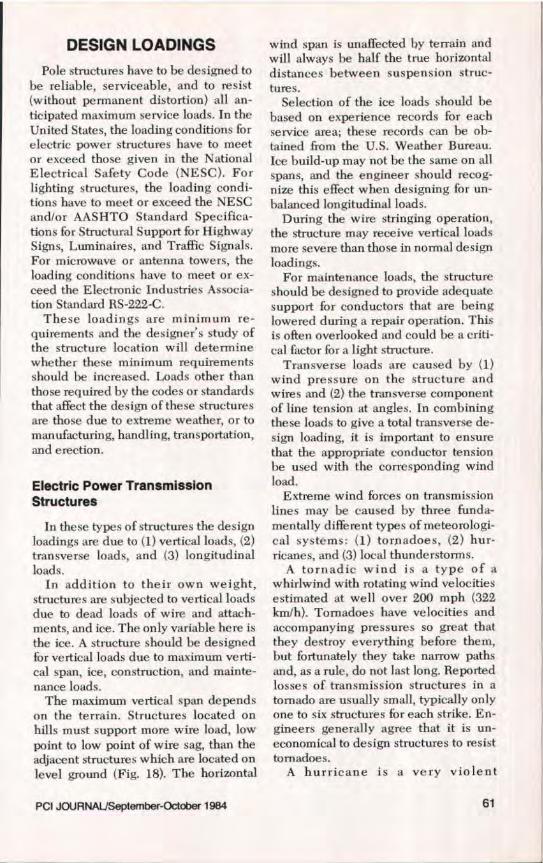
In Japan there is a nationwide use ofprestressed concrete poles for electricpower transmission, distribution andsubstations, overhead power transmis-sion for railroads, telephone and com-munication systems, lighting standards,flood-lighting, and wire netting sup-ports. In recent years Japan has becomean exporter of large quantities of poles toall of southeast Asia, in addition to thewest coast of North America (Fig_ s.11-14).
Prestressed concrete poles have a!-so been made and used for power dis-tribution in New Zealand, Australia,India, and South Africa since the mid1950s.
In the United States reinforced con-crete poles were used by some electricutilities in the 1930s, but the first pre-stressed concrete poles were used byFlorida Power Corporation in 1954when they designed a 66 kV pole and anH-section to use in a 110 kV H-framestructure. By the early sixties, FloridaPower Corporation and Florida Powerand Light Company were using pre-stressed poles for lighting and powerdistribution. Today, the Florida utilitiesare still using statically cast square pre-stressed poles for lighting, distribution,and for some transmission up to 230 kV(Fig. 15).
In 1962, the Eugene Water and Elec-tric Board of Eugene, Oregon, con-structed I mile (1.6 km) of double-circuit H-frame 115 kV transmission linealong the McKenzie River, using a ta-pered I-shaped prestressed concrete
Fig. 10. Communication structure(Western Europe).
pole as an aesthetic challenge. Theyhave continued to use the I-shaped pre-stressed pole as a single circuit pole, andas a single and double circuit H-frametransmission structure (Fig. 16).
In 1964, the Virginia Electric andPower Company (Vepco) built its firstprestressed concrete pole structures, atapered I-shaped pole (Fig. 17). Thesepoles were used to rebuild and upgrade,from 34.5 to 115 kV, a 3-mile (4.8 km)water crossing in the coastal area ofNorth Carolina. Each pole was set in apost-tensioned, centrifugally-spun con-crete cylinder pile of predetermined
PCI JOURNAUSeptember-October 1984 57
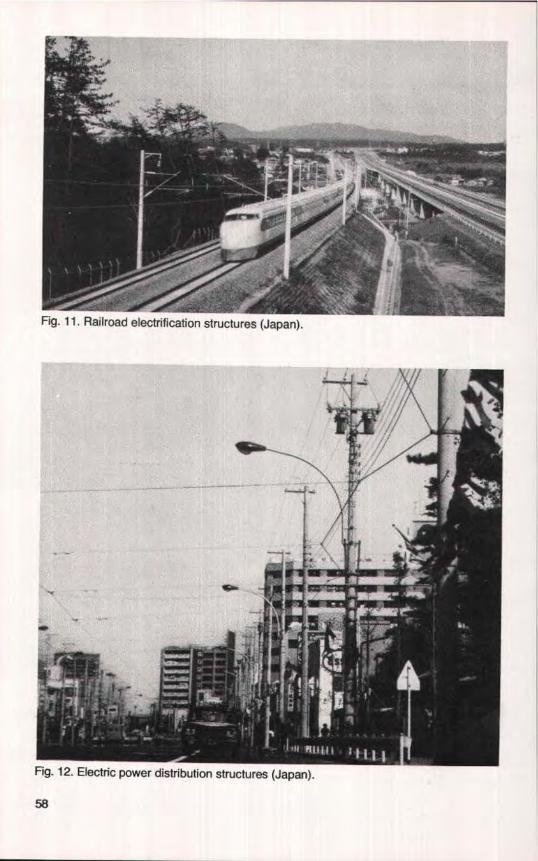
Fig. 12. Electric power distribution structures (Japan).
1-ig. 11. Railroad electrification structures (Japan).
58

length. The piles were jetted and driveninto the bottom of the Currituck Sound.Vepco in 1966, used a static cast, taperedsquare pole for lighting distribution andsome 115 kV transmission.
In 1968 Vepco changed fromstatically cast poles to centrifugally-spun prestressed poles having ta-pered, hollow, circular cross sec-tions. This type of pole is still beingused for lighting, distribution, transmis-sion, and substation structures.
Currently, there are several utilities inthe United States and Canada using anumber of different types and shapes ofprestressed concrete poles for lightingand for power transmission and dis-tribution.
Fig. 13. Power transmission structures(built in Japan).
Fig. 14. Telephone line structures (Japan).
PCI JOURNAL/September-October 1984 59

Fig. 15. Power transmission structure(Florida Utility Company).
A --H-Fig. 16. Power transmission structure(Eugene Water and Electric Board).
Fig. 17. Power transmission structure(Virginia Electric and Power CompanyCurrituck Sound Crossing). Built in 1964,these tapered I-shaped prestressedconcrete poles were used to upgrade a34.5 to 11.5 kV, 3 mile (4.8 km) watercrossing in North Carolina. The poles weremanufactured using the centrifugally-spuncylinder pile method.
DESIGN LOADINGS
Pole structures have to be designed tobe reliable, serviceable, and to resist(without permanent distortion) all an-ticipated maximum service loads. In theUnited States, the loading conditions forelectric power structures have to meetor exceed those given in the NationalElectrical Safety Code (NESC). Forlighting structures, the loading condi-tions have to meet or exceed the NESCandlor AASHTO Standard Specifica-tions for Structural Support for HighwaySigns, Luminaires, and Traffic Signals.For microwave or antenna towers, theloading conditions have to meet or ex-ceed the Electronic Industries Associa-tion Standard RS-222-C.
These loadings are minimum re-quirements and the designer's study ofthe structure location will determinewhether these minimum requirementsshould be increased. Loads other thanthose required by the codes or standardsthat affect the design of these structuresare those due to extreme weather, or tomanufacturing, handling, transportation,and erection.
Electric Power TransmissionStructures
In these types of structures the designloadings are due to (1) vertical loads, (2)transverse loads, and (3) longitudinalloads.
In addition to their own weight,structures are subjected to vertical loadsdue to dead loads of wire and attach-ments, and ice. The only variable here isthe ice. A structure should be designedfor vertical loads due to maximum verti-cal span, ice, construction, and mainte-nance loads.
The maximum vertical span dependson the terrain. Structures located onhills must support more wire load, lowpoint to low point of wire sag, than theadjacent structures which are located onlevel ground (Fig. 18). The horizontal
wind span is unaffected by terrain andwill always he half the true horizontaldistances between suspension struc-tures.
Selection of the ice loads should bebased on experience records for eachservice area; these records can be ob-tained from the U.S. Weather Bureau.Ice build-up may not be the same on allspans, and the engineer should recog-nize this effect when designing for un-balanced longitudinal loads.
During the wire stringing operation,the structure may receive vertical loadsmore severe than those in normal designloadings.
For maintenance loads, the structureshould be designed to provide adequatesupport for conductors that are beinglowered during a repair operation. Thisis often overlooked and could be a criti-cal factor for a light structure.
Transverse loads are caused by (1)wind pressure on the structure andwires and (2) the transverse componentof line tension at angles. In combiningthese loads to give a total transverse de-sign loading, it is important to ensurethat the appropriate conductor tensionbe used with the corresponding windload.
Extreme wind forces on transmissionlines may be caused by three funda-mentally different types of meteorologi-cal systems: (1) tornadoes, (2) hur-ricanes, and (3) local thunderstorms.
A tornadic wind is a type of awhirlwind with rotating wind velocitiesestimated at well over 200 mph (322kmlh). Tornadoes have velocities andaccompanying pressures so great thatthey destroy everything before them,but fortunately they take narrow pathsand, as a rule, do not last long. Reportedlosses of transmission structures in atornado are usually small, typically onlyone to six structures for each strike. En-gineers generally agree that it is un-economical to design structures to resisttornadoes.
A hurricane is a very violent
PC! JOURNALISeptember-October 1984 61

V
V I V2
VERTICAL SEMISPANS
Fig. 18. Vertical and horizontal design spans for pole structure,
windstorm out of the West Indies; thesewindstorms usually blow up in summerand fall of the year. On the Beaufortscale, winds of over 75 mph (121 krn/h)are classed as hurricane winds. Thestorm usually starts as a tropical depres-sion in the Atlantic Ocean. As it movesalong its path, the counter-clockwisewinds around the center grow in inten-sity in the area covered. Winds of 100 to120 mph (161 to 193 km/h) are common,Hurricanes cause great destruction eachyear to parts of the Caribbean Islands,Gulf, and East Coast States. In thePacific Ocean, these storms are calledtyphoons. Engineers in the areas af-fected by hurricanes have to pick a de-sign for extreme wind speed that is abalance between risk of failure andstructure cost.
Thunderstorms and squall lines aremore localized and random in their im-pact and are the main concern of en-gineers in most parts of the country.
To determine the design wind load,the engineer needs to know a designwind velocity and a suitable equation bywhich it can be converted to pressure onthe transmission line. The design windloads may be determined for a geograph-
ical area by using the annual extremefastest-mile wind charts developed bythe U.S. Department of Commerce—Environmental Science Service Ad-ministration using statistical prob-ability.
Charts are available for elevations of30, 60, and 90 ft (9, 18, and 27 m) aboveground, in varying mean-recurrenceintervals. To realize what these chartsare, consider the wind velocity record ofFig. 19. It represents a 5 minute windvariation at the location of a certainstructure during the most severe stormof a given year.
The 5 minute average and the peak2-second gust are self-explanatory. Thefastest mile is defined as the averagevelocity at which 1 mile (1.6 km) of airpasses the anemometer.
The operational life of the transmis-sion line should determine the mean re-currence interval chart that is used.Utilities normally consider the life of awood pole line at about 25 to 30 years,steel and prestressed concrete structurallines at about 60 years. It is recom-mended that a 50-year mean recurrenceinterval be used for prestressed concretestructure lines.
62

VELOCITY AT A I PEAK GUST OF 2Sv
—FASTEST MILE OR IM v
I I 1 ^
1 11 1
5 MIN.O 4 - I MIN.
Fig- 19. Wind velocity strip graph for designing pole structure.
A well-known formula for increasingwind speed according to height is:
V ^ h )V
lIn (1)
n= ^ 0
whereV,, = adjusted velocity, mphV. = annual extreme fastest mile
wind chart velocity, mphh = adjusted elevation, ftho = elevation ofVa , ftn = constant dependent on surface
roughness (varies from 2 to 7)A value of 7 for n is normally used for
level or slightly rolling land with scat-tered trees or buildings. The formula isnot reliable for use in decreasing windspeeds below 30 ft (9 in). Wind velocity,in mph, may be converted into windpressure by using the following formula:
For wind pressures on cylindricalsurfaces:
P = 0.0025 V$ (2)
For wind presures on flat surfaces:
P = 0.0042 V 2 (3)
whereP = wind pressure, psf, on projected
area of surfaceV = design wind velocity, mph
Wind Pressure on Structures
There appears to be general agree-ment that short wind gusts are largeenough to envelop a transmissionstructure. For this reason, the designwind pressure on a transmission struc-ture should be determined from a gustvelocity. Relationships between peakgust and fastest mile have been de-veloped; one such expression used bythe industry is:
Peak gust = 1.3 x Fastest mile (4)
To find the design wind pressure on atransmission structure, the wind pres-sure formula should be adjusted to:
P = k (1.3V)2 (5)
where k is the surface shape coefficient.The same problems of selecting wind
velocity and suitable equations alsoarise with regard to the transmissionline. It has been mentioned that a shortgust of wind could envelop a structure,but it cannot envelop a span oftransmis-sion line approximately 1000 ft (305 m)in length. Field tests have shown that areduction factor can be applied to mod-ify the conventional drag coefficients inpicking a wind pressure on a conductor.After the conductor design pressure has
PCI JOURNALJSeptember-October 1984 63
been determined, an effective windspan factor (fP,,) of 0.6 should beapplied to all spans in excess of 1000 H.For span lengths between 300 and 1000R (91 and 305 m), this factor will varyand should be determined as follows:
= 1.0 – 0.4 (S – 300)/700 (6)
where S is the span length, ft.
For spans of 300 ft (91 m) or less, theeffective wind span factor should be 1.0.
Extreme wind with heavy ice isanother condition the engineer has toconsider. Maximum winds that occurduring sleet storms are usually lower inintensity than winds at other times inthe same area. The engineer must re-view local weather records to determinethe range of wind velocities that occurduring freezing precipitation. Then,using the appropriate ice loading, hemust calculate whether the wind-with-ice condition is more critical as a trans-verse load than the higher wind on bareconductors.
A study made in Canada of maximumwind recorded during freezing precipi-tation and for one day after, tabulatedlocal variation. This technique is valu-able for the engineer because data canbe taken directly from weather records,thus showing winds which are likely tooccur in a given area when there is iceon the conductor.
Transverse Loads and Line Angles
The transverse loading upon thestructure must be taken as the resultantload equal to the vector sum of thetransverse wind load and the resultantload imposed by the wires due to theirchange in direction. In deriving theseloadings, a wind direction must be takenwhich will give the maximum resultantload. Proper reduction is made in load-ing to account for the reduced windpressure on the wires resulting from theangularity of the application of the windto the wires.
In areas of moderate to heavy iceloadings, this transverse component willtend to control the design of angle anddead end structures. In areas of no ice,or where only minor icing occurs, careshould be taken in determining the ef-fect of wind on line tension, being sureto use the same design wind velocity tocalculate line tension as is used to cal-culate the strength of the structure. Careis necessary also in calculating which ofthese two "maximum" conditions iscritical:
1. Maximum wind velocity with cor-responding line tension
2. Maximum line tension with corre-sponding wind velocity
Longitudinal Loading
For years, transmission structureshave been designed using a longitudinalloading condition of a broken conductorand/or overhead shield wire dead load.In recent years, the trend has been touse larger conductors, and many utilitieshave regarded the broken wire condi-tion as being too conservative.
Longitudinal loads can he imposed onstructures by many conditions otherthan broken wires. The following areseveral other conditions under which astructure will he subjected to longitudi-nal loadings:
1. Conductor or overhead shield wirestringing loads
2. Unequal spans3. Wind parallel to the line4. Wind at 45 deg to the line5. Ice-unloading unbalance6. Loss of an adjacent structureDuring stringing operations there are
instances where the stringing block mayjam momentarily, or a sleeve passingthrough the block may "hang up,"causing some longitudinal load to beapplied to the structure. Stringingequipment located too close to a struc-ture may impose detrimental verticaland longitudinal loads to the structureduring wire stringing operations.
64

Table 1. Overload capacity factors for metal and prestressedconcrete structures (NESC Table 261-2).
Strength
Overload capacity factors
Grade B Grade C
Vertical strength 1.50 1.10Transverse strength 2.50 2.20Longitudinal strength
At crossingsIn general 1.10 No requirementAt dead ends 1.65 1.10
ElsewhereIn general 1.10 No requirementAt dead ends 1.65 1.10
Note: The factors in this table apply for the loading conditions of NESCRule 250B. For extreme wind loading conditions, Sec NESC Rule 260C.
In mountains or very hilly areas, it ispossible to have longitudinal loadscaused by unequal spans. This is due tothe difference in tension in the wires inadjacent spans resulting from unequalvertical loading and/or unequal spanlength.
Winds not only blow on the structuresin the transverse direction, but in thelongitudinal direction and at all anglesin between. The structures should at aminimum be designed to withstand thewind plus gust which may envelop it inthe longitudinal direction. Windsblowing at 45 deg to the line can exertlongitudinal forces on the structure dueto wind on the wires and wind on the,,tructure itself. These longitudinalforces should be investigated.
Ice -unloading unbalance is now themost commonly used longitudinalloading. The dropping of ice from one ormore wires in different combinations isused by a designer to provide torsionalstrength in addition to longitudinalstrength in a structure.
Ice may build up on wires in only afew spans causing longitudinal loads. Inmost cases, ice builds fairly uniformlyon all spans, and usually drops from onespan before another. Ice frequently fallsin large chunks when it starts to melt. As
these chunks fall from one span, theswing of the insulator strings in a lon-gitudinal direction is noted. This has leddesigners to use only a percentage of theice-no-ice tension differential as thelongitudinal loading. The longer the in-sulator string, the more the tension dif-ferential is reduced.
Under Section 25, the NESC sets theminimum weather loading condition forwhich a transmission line is to he de-signed. These minimum weather load-ings must be values of loading resultingfrom the application of Rule 250-B -Combined Ice and Wind Loading orRule 250-C — Extreme Wind Loading,whichever is the greater.
In the design of pole structures, theterm "overload capacity factors" is in-terpreted to mean that the structureshould support, without permanent set,the maximum loadings to which it willbe subjected multiplied by the appro-priate overload factors,
The general loading requirements setforth in Section 25 of the NESC are to bemultiplied by overload Factors set forthin Section 26, "Strength Requirements"depending on type of structure, to es-tablish the design loads (see Table 1).
The minimum strength of any polestructure must be sufficient to with-
PCI JOURNALJSeptember-October 1984 65
The following loads are typical ofthose usually considered:
T^
Hif
Hz1f1
T2
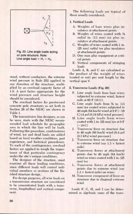
Fig. 20. Line angle loads actingon pole structure. Note:Line angle load = H, + HZ.
stand, without conductors, the extremewind pressure in Rule 252 applied inany direction of the structure, multi-plied by an overload capacity factor of1.0. A gust factor appropriate for thewind pressure and structure heightshould be considered.
The overload factors for prestressedconcrete pole structures as set forth inSection 26 of the NESC are shown inTable 1.
The transmission line designer, as canbe seen, starts with the NESC recom-mended load schedule for geographicarea in which the line will be built.Following this procedure, combinationsof wind, ice and dead loads are addedbased on local weather conditions, pastexperience, and historical precedence.To each of the contingencies, overloadfactors are applied to weigh the impor-tance of that particular contingencyunder the site's unique conditions.
The designer of the structure, mustexamine all these loading conditions,since different loads will control indi-vidual members or sections of the fin-ished structure design.
For design purposes, all wire loads ona transmission structure are consideredto be concentrated loads with a trans-verse, longitudinal and vertical compo-nent.
1. Vertical Loads
A. Weights of bare wires plus in-sulators at attachment points
B. Weights of wires coated withradial in. (13 mm) ice plus in-sulators at attachment points
C. Weights of wires coated with 1 in.(25 mm) radial ice plus insulatorsat attachment points
D. One man plus equipment at criti-cal points
E. Vertical components of stringingloads
Loads A, B, and C are calculated asthe product of the weight of wires(coated or not) per unit length by thevertical span V.
2. Transverse Loads (Fig. 20)
F. Line angle loads from bare wiressubjected to extreme wind, fastestmile at 60F(16C).
G. Line angle loads from Vs in. (13mm) ice coated wires subjected to40 mph (64 km/h) wind at 0 F (-18C) [4 psf (0.19 kPa) wind prssure]
H. Line angle loads from wirescoated with I in. (25 mm) ice at 0 F(-18 C)
I. Transverse force on structure dueto 40 mph (60 km/h) wind [6.4 psf(0.3 kPa) wind pressure I
J. Transverse force on structure dueto extreme wind (say 1.3 x fastestmile)
K. Transverse forces at attachmentpoints due to 40 mph (64 km/h)wind on wires coated with 1 in. (25mm) ice
L. Transverse forces at attachmentpoints due to extreme wind (say1.3 x fastest mile) on wires
M. Transverse component of force onstructure due to diagonal extremewind
Loads F, G, H, and I can be deter-mined as algebraic sums of the trans-
66

verse components of tensions of at-tached wires.
Note that transverse forces K and Lare the products of wind forces per unitlength of wire by appropriate windspans.
3. Longitudinal Loads
N. Unbalanced wire tensions due tounequal vertical loads, differentspan configurations, etc.
0. Longitudinal force on structurefrom extreme wind (say 1.3 x fast-est mile)
P. Longitudinal component of forceon towers from diagonal extremewind
Q. Longitudinal component ofstringing and construction loads
R. Broken wires — Loads should re-flect experience under actuaI con-ditions
S. Ice-unloading unbalance — Ice-no-ice tension differential x per-cent reduction due to insulatorswing
T. Dead-end tensions from bare ca-bles subjected to extreme wind at60F(16C)
U. Dead-end tensions from ;/s in. (13mm) ice coated wires subjected to40 mph (64 km/h) wind at 0 F (-18C)
V. Dead-end tensions from 1 in. (25mm) ice coated wires at 0 F (-18C)
Design loads for prestressed concretestructures are ultimate loads. The fol-lowing design loading conditions, loadmultiplied by overhead capacity factor,can be used at overhead shield wire andconductor points:
NESC — Heavy Loading
Case I 1.50 (B) 2.50(K) + 1.65 (G)(Vertical load) (Transverse load)
Extreme wind
Case II 1.50 (A) 1.1 (L) + 1.1 (F)(Vertical load) (Transverse load)
vs
-- Ts
fr ç
L^^v --r T
—W V
T = transverse loadL = longitudinal loadV = vertical loadw = wind on structureV, . L, T, = shield wire loads
Fig. 21. Design loads ("load tree")acting on pole structure.
Heavy Ice
Case I11 1.50 (C) 1.1 (H)(Vertical load) (Transverse load)
1.1(S)(Longitudinal load)
The above are the basic loading cases.This is the procedure the utility en-gineer goes through in supplying thedesigner with the "load trees" (Fig. 21)required to design prestressed concretepole structures.
Lighting Structures
Lighting pole structures must meet orexceed the design loadings of the NESCand/or AASHTO Standard Specifica-tions for Structural Supports for High-way Signs, Luminaires and Traffic Sig-nals, and include (1) dead load, (2) liveload, (3) ice load, and (4) wind load.
In addition to its own weight, thedead load includes all permanently at-tached fixtures, including hoisting de-
PCI JOURNAL/September-October 1984 67
vices and walkways provided for ser-vicing of luminaires, if required.
Live load need not be applied tostructural supporting members. Theonly member requiring a live load de-sign would be the walkway and ladders.
The ice load of 3 psf (0.14 kPa) isapplied only to the attached fixtures,ladders, walkways, luminaires or signs,and is based on 0.50 in. (13 mm) of ice at60 pef (961 kg/ms).
Wind speeds are based on the 25-yearmean recurrence interval wind speedmaps developed by the U.S. Depart-ment of Commerce — EnvironmentalScience Service Administration andadjusted for height. Wind pressure onstructural supports is computed from:
P = 0.00256 (1.3V)2 C d C, (7)
whereCd = a dimensionless drag coeffi-
cient that varies with the shapeof the support structure re-ceiving the wind loading
C„ = coefficient of height, derivedfrom (H/30)1-T
H = height at which pressure is de-termined
V = wind speed at 30 ft (9 m) height1.3 = gust factorThe wind load on the structure must
be determined by the areas of horizontaland vertical supports, luminaires andsignals and must be applied to the sur-face area seen in normal elevation.
Antenna Support Structures
Antenna support structures must meetor exceed the design loads of the Elec-tronic Industries Association, EIA Stan-dard RS-222 latest revision, and include(1) dead load, (2) ice load, (3) wind load,and (4) limit values of twist, sway, anddisplacement.
In addition to its own weight, thedead load includes all permanently at-tached fixtures, antenna assemblies,transmission lines, reflectors, conduits,
lighting, climbing facilities, platformsand signs.
The ice load is based on solid ice[density of 56 pef (897 kg/m s) J applied tothe attached fixtures. This standard doesnot specifically state an ice thicknessrequired. Consideration to its locationand the climatic conditions should hegiven to an ice thickness requirement inpreparing the specifications.
Wind loads are defined as the forceand torques produced by a specifiedunit horizontal wind pressure acting onthe tower, antenna assemblies, reflec-tors, and other fixtures attached. In allcases, the specified ice coating shouldbe included as part of the projected area.Minimum horizontal wind pressure inpounds per square foot (psf) are referredto on a map chart called "Wind LoadingZones" which is part of the standard.For towers under 300 ft (92 m), Zone A—30 psf(1.4 kPa); Zone B — 40 psf (1.9kPa); Zone C — 50 psf (2.4 kPa); thepressure is assumed to be applied uni-formly over the entire height of thestructure.
Tower twist is defined as the hori-zontal angular displacement of thetower from its no wind load position atthat elevation. Tower sway is defined asthe angular displacement of a tangent tothe tower axis at that elevation from itsno wind load position at that elevation.Tower displacement at any elevation isdefined as the horizontal displacementof a point on the tower axis from its nowind load position at that elevation.A table of allowable twist and swayvalues for microwave tower-antenna-reflector systems is attached to the.standard.
Shape
The shape of poles has a bearing onthe design and manufacturingtechnique. The normal sections adoptedin various countries are shown in Fig.22. The simplicity of the square andrectangular solid section poles of small
68

OH
Hll-(Fig. 22. Typical cross sections of prestressed concrete poles.
length, up to 40 ft (12 m), make themeasy to manufacture, facilitate position-ing of steel at corners giving maximumresisting moment for a given depth, andoccupy less space in transportation. Cir-cular hollow sections seem to be idealfor the longer poles.
Cylindrical hollow poles have theseadvantages: less weight; equal strengthin all directions eliminating any specialcare during handling, transportation anderection; a denser and higher quality ofconcrete from the spinning process. Theabsence of corners and the smooth,dense minimum surface area givegreater protection against corrosion fail-ure. However, there is a considerabledivergence of opinion concerning thebest shape of a pole.
Vierendeel poles are also widelyused. Their use has been in structures of33 ft (10 m) in length and above andwhere higher transverse loads are in-volved. They have the disadvantages ofhaving larger exposed areas and thinelements, leading to possible concretecracking and corrosion. It should benoted that if the horizontals are notspaced further apart, they will be mis-used for climbing. East European coun-tries have used the Vierendeel pole in a"Pi" structure or H-frame structure forcarrying transmission lines.
DESIGN CRITERIADesign criteria for poles vary signifi-
cantly from country to country. How-ever, poles generally act as a cantile-vered structure, and should be designedand/or analyzed as a tapered memberwith combined axial and bending loads.The shear forces are very small whencompared to the bending moments; thedeflections are relatively large, and thishelps to provide the resilience. Theaxial loads, being small, are generallyignored except when the structure isguyed.
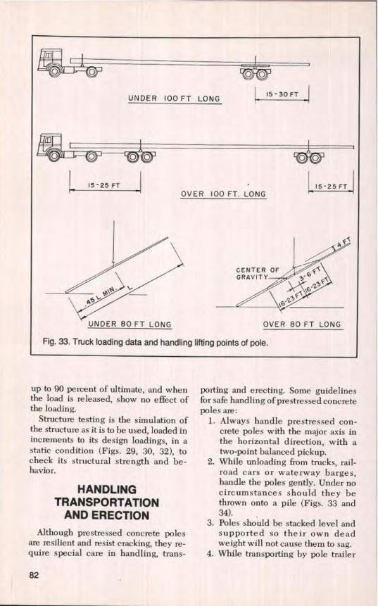
It is essential in the design to examinethe stresses induced by handling, trans-portation and erection. Under severeconditions of handling, these may ex-ceed in-service stresses. The stressesimposed during transportation will de-pend on the method of transportationavailable. The common lifting pointsused are the third points or, in somecases, the center of gravity. Erectionstresses will likewise depend on thepoint at which the pole is lifted. In con-sidering the latter, the weight of thecross-arm and/or other attachmentsshould not be overlooked in calculatingthe position of the center of gravity.
The concrete structure should beproportioned so that the deflection due
PCI JOURNAL1September-October 1984 69
to the service loads will not he detri-mental to the strength, serviceability re-quirements, and the aesthetic qualitiesof the structure.
The pole has to withstand equalbending moments in opposite directionsand therefore concentric prestressing isprovided. Hence, the magnitude of theprestress can only be about one-half ofthe value that can be used for bending inone direction. This is an important dif-ference in the design of prestressedconcrete poles compared to other typesof prestressed structures.
The ultimate moment capacity of thepole at various sections is a function ofthe strains of prestressing steel and con-crete and the effective stresses in theprestressing steel. Loaded to failure, thepole will fail in one of the followingmodes at the section which undergoes ahigher ratio of bending design momentto ultimate moment capacity.
1. Rupture of steel — The pole mighthave one or more sections having alow percentage of steel, i.e.,under-reinforced sections. The ul-timate strength of the steel is at-tained before the concrete hasreached a highly plastic state.
2. Crushing of concrete — The polemight have one or more sectionshaving a high percentage of steel,i.e., over-reinforced sections. Thesteel stresses do not exceed theyield point, and failure results inthe crushing of concrete.
3. Failure of both steel and concrete— Sections of the pole may have abalanced behavior of the two mate-rials. The steel would he stressedinto the plastic range and the con-crete would attain the maximumstrain defined by its capability.
To achieve the balanced behavior inthe third failure mode in a tapered polepresents a practical problem regardingthe application of prestress. However,systems have been developed to reducethe effective prestress in the upper por-tions of the tapered pole by preventing
bond or by dead-ending some of thetendons along the length of the pole.
Another design factor is the flexuralmoment that causes initial cracking onthe tension face of the pole. This is thepoint at which all the prestress and thetension capacity of the concrete hasbeen used. This has been found to beabout one-half of the ultimate momentof the fully prestressed sections. Thedesign permits the pole to exceed thecracking moment, but not to fail underultimate design conditions.
So far the paper has concentratedupon fully prestressed concrete poles,but some of the larger poles used fortransmission line structures in Europeand India are partially prestressed. Thedefinition of each follows:
Full Prestressing — A concretestructure is fully prestressed if thestresses due to bending perpendicularto the direction of prestressing calcu-lated for the full design service load arecompressive. (It should be noted thatfull prestressing does not provide abso-lute safety against tensile stresses orcracking due to shear, torsion, temper-ature effects or imposed deformations.)
Partial Prestressing — A concretestructure is partially prestressed if sub-stantial tensile stresses or cracks per-pendicular to the direction of pre-stressing can occur in the concreteunder the full design service load. Suchcracks may be of limited width to satisfydurability or appearance purposes. (Inthese cases, additional mild steel rein-forcement is added in the direction ofthe tendons to meet ultimate strengthrequirements.)
Reinforced Concrete — A reinforcedconcrete structure is one in which noneof the steel reinforcement is prestressedduring construction.
The full design service load is theequivalent of the design loading beforethe applicable code overload capacityfactors have been applied.
Partially prestressed poles will con-tain both prestressing tendons and mild
70

steel reinforcement. The reinforcementshould have high bond characteristics.The degree of prestressing will influ-ence the behavior of the structure underservice loading with regard to deflec-tion, tensile stresses and cracking, andall of the steel will operate to provide anadequate factor of resistance at the ulti-mate stage.
The service load should be consid-ered in two parts:
(a) That portion of the load which ispermanently or frequently occur-ring.
(b) The maximum possible serviceload which may be applied.
In Condition (a) the prestress shouldbe such that control is exercised in oneor more of the following ways:
1. Control of cracking, either nocracks or crack width limited to adefined amount,
2. Control of concrete bending ten-sile stress in the section underload, either no tension or a definedmaximum tensile stress transverseto the direction of prestressing.Stress created by secondary mo-ments may also need to he consid-ered.
3. Control of deflection, zero deflec-tion or a defined maximum value,positive or negative, in relation tothe span.
For Condition (h) it should he ac-cepted that cracks occur and themember deflects more than under Con-dition (a) loading, but these cracks willclose and the deflection will reduce onremoval of the load. It must be ensuredthat the structure will return to a condi-tion complying with the requirementsfor Condition (a) when the infrequentload is removed. Investigations at Con-dition (h), therefore, need only be suchas to ensure that the structure returns tothese conditions and perhaps that no ex-cessive deflection will occur under thismaximum load.
The design basis for partially pre-stressed poles consists, therefore, es-
sentially of three stages:1. Assessment of prestressing force to
satisfy serviceability requirementsunder permanent or frequently oc-curring load.
2. Assessment of ultimate strength ofmember (in bending, shear, etc.).
3. Checking cracking and deflectionconditions under the maximumpossible service load.
It is necessary to control the extent ofcracking at serviceability conditions inorder to ensure durability of the steelagainst corrosion and to ensure an ac-ceptable surface appearance. The de-gree of cracking which can be allowedmust depend on the aggressiveness ofthe environment to which the structurewill be subjected, and the quality of theconcrete being used.
In designing prestressed concretepoles by the codes of different countries,a certain cracking resistance under sus-tained loads is specified, though theloads and requirements about the ad-missibility of cracks differ. The methodsof controlling strength, rigidity, and theprestress in the steel and the concretediffer as well. In view of this, it is dif-ficult to compare the efficiency of polesused in different countries.
In East Germany, poles are designedby the ultimate load method for State 2to provide a prestressing value compati-ble with the allowable crack widthunder the average and maximum loads.The design is based on the regulationsin TCL 0-4227 and TCL 112-0491.
In West Germany, the loads on poles,their interaction under various workingconditions and the design methods arebased on a number of documents inforce, including: DIN 4228-1964, DIN48353, DIN 1055, VDE 0210/5.62, andDIN 4227. Checks on stresses are madeunder average and exceptional loadingcases. The standard design restricts thecrack width to less than 0.1 mm (0.004in,) with a spacing of about 100 mm (4in.).
In the Soviet Union, poles are de-
PCI JOURNAUSeptember-October 1984 71
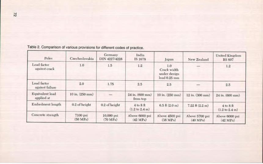
Table 2. Comparison of various provisions for different codes of practice.
Germany India United KingdomPoles Czechoslovakia DIN 4227/4228 IS 1678 Japan New Zealand BS 607
Load factor LO 1.5 1.2 1.0 — 1.2against crack Crack width
under designload 0.25 mm
Load factor 2.0 1.75 2.5 2.5 — 2.5against failure
Equivalent load 10 in. (250 mm) — 24 in, (600 mm) 10 in. (250 min) 12 in. (300 mm) 24 in. (600 min)applied at from top
Embedment length 0.2 of height 0.2 of height 4 to 8 ft 6.5 ft (2.0 m) 7.22 ft (2.2 m) 4 to SR(1.2to2.4m) (1.2to2.4m)
Concrete strength 7100 psi 10,000 psi Above 6000 psi Above 4500 psi Above 5700 psi Above 6000 psi(50 MPa) (70 MPa) (42 MPa) (.38 41 Pa) (40 MPa) (42 MPa)
signed in accordance with the relevantstandards and codes using the limit statemethod (SNiP I1-C.1-62, SNiP II-1.9-62and others). Design by strength, defor-mation as well as crack width are cov-ered by this method, The first limitstate, ultimate strength, must always bechecked. The second limit state needsonly to check the behavior of terminalpoles under emergencies. The thirdlimit state requires the behavior of everyconcrete member to be checked fornormal service loads.
In the United States at this time, it isrecommended that prestressed concretepoles be analyzed for ultimate strengthin accordance with the basic provisionsgiven in the Building Code Require-ments for Reinforced Concrete, ACI318-83, modified to include the effectsof prestressing. Pole structures shouldbe designed to withstand the maximumof the forementioned loading condi-tions, including the overload factors,without exceeding the ultimate strengthof the pole. Under normal working con-ditions, the design should not exceedthe cracking moment.
In Canada under the proposed newCSA Standard A14-M, Concrete Poles,poles may be designed in accordancewith CSA Standard A23-3, Design ofConcrete Structures for Buildings, with-out recourse to classification testing,provided that substantive information isavailable for presentation to verify thatthe poles, as manufactured, are in accor-dance with the design assumptions.Poles may also he designed using em-pirical coefficients obtained from clas-sification tests, conducted in accordancewith Clause 7 — Classification TestingProcedures and within some statedlimitations.
Table 2 compares the major provi-sions of the various codes of practice andlists some of the basic code require-ments.
It would be helpful to have some in-ternational standardization of designmethods for pole structures fulfilling the
same functions and operating undersubstantially identical conditions.
MANUFACTUREThe successful manufacture of pre-
stressed concrete poles depends on thelocal conditions and available equip-ment. It can be done in specialized fac-tories using the sophisticated spinningmethod with steam and/or water tankcuring, or as in India, in remote areas onsite locations, using portable preten-sioning beds, local untrained labor, aircuring and specially designed bullockcarts for transporting and erecting thepoles. The following are the principalmanufacturing methods.
1. Industrial manufacturing of com-plete poles at specialized factories:(a) By centrifugal casting method
with demountable steel forms;(b) By vibration, compacting on a
bed with the molds laid hori-zontally;
(c) By compaction in a machinewith either transverse or lon-gitudinal vibration.
2. Manufacture may be on site withpoles placed horizontally.
3. Poles may he made from precastsections which are assembled onsite by post-tensioning or bysplicing, or may be partly preas-sembled in special casting yards.
In most of Europe and Japan, concretepoles are economically mass producedby well equipped plants using the cen-trifugal casting method. The basic man-ufacturing equipment needed is thespinning machine and the steel forms.The spinning machines are of heavy-duty, roll-bench type and have sets ofspinning wheel assemblies at 10 Ft (3 m)intervals. The spinning wheel as-semblies are hard face, long wearingwheels mounted on extra large anti-friction rollers and ball bearings in to-tally sealed pillow blocks. The machineis normally driven by a full length
PCI JOURNAL/September-October 1984 73
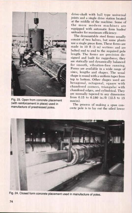
Fig. 23. Open from concrete placement(with reinforcement in place) used inmanufacture of prestressed poles.
drive-shaft with ball type universaljoints and a single drive station locatedat the middle of the machine. Some ofthe more modern machines areequipped with automatic form loader!unloader for maximum efficiency.
The demountable steel forms usuallyconsist of two halves, but some plantsuse a single piece form. These forms aremade in 10 ft (3 m) sections and arebolted end to end to the required polelength. The forms are precision de-signed and built for ruggedness; theyare statically and dynamically balancedfor smooth, vibration-free running.Forms are available in a wide range ofsizes, lengths and shapes. The usualshape is round with a uniform taper fromtop to bottom. Other shapes used arehexagonal, octagonal, square withchamfered corners, triangular withchamfered edges, and cylindrical. Theyare normally tapered to any dimensionfrom 0.15 to 0.180 in./ft (12.5 to 15mm/m).
The process of making a spun con-crete pole is to lay out the oiled lower
ii:
I
Closed form concrete placement used in manufacture of poles.Fig. 24
74

Fig. 25. Closed form concrete placement used in manufacture of poles.
half of the form, to place full length spi-ral wire wrap, to pull reinforcing strandor wire through spiral wrap to anchorheads, then to chuck and apply a smallamount of stress, In plants using "openform filling" (Fig. 23), the form is closedafter it has been filled with a precalcu-
lated amount of concrete and final pre-stressing takes place after the form hasbeen filled and fully assembled. Inplants using "closed form filling" (Figs.24 and 25), the form is closed irn-mediately after placing the reinforce-ment, final prestressing takes place after
Fig. 26. Pole spinning operation.
PCI JOURNALiSeptember-October 1984 75

Fig. 27. Pole manufacture in India using Hoyer's long line method.
the form has been fully assembled, butbefore a precalculated amount of con-crete is pumped or dumped into it.
The form is then placed on the spin-ning machine where it is spun for sev-eral minutes. Two speeds are used inthe process. At the lower speed, themixture is divided uniformly along theform and the cylindrical cross section isformed. At the high speed, the tremen-dous centrifugal force created by spin-ning extracts excess water and consoli-dates the mix to an extremely dense,high strength concrete (Fig. 26).
After spinning, the form is taken to thesteam curing area, where the pole iscured with low pressure steam for aperiod of time until the strength of theconcrete in the pole has attained at least3500 psi (24 MPa). The prestressed wireor strand is then released; the pole is
dressed up and air cured for 28 daysbefore shipping.
The Swiss BBRV prestressing systemis also being applied to the manufactureof poles. In this system high tensile wireis anchored at the pole ends by means ofbutton heads and special anchorwashers. Using this system and somespecial auxiliary equipment, spun con-crete poles are being made for electricpower lines.
Vibration techniques are widelyapplied in the manufacture of concretepoles. In East Germany, a vibrationmethod known as Mensel's method isused where lightweight horizontalmolds are carried on mobile framesstrong enough to take the tensilestresses of the prestressing steel, Aproduction line system is used, and themolds and equipment circulate so that
76

the workers do not have to move around.The production system embraces someof the processes used with othermethods of production and includes onespecial feature. A formwork core oc-cupies the space which will be the innercavity of the pole, and this is rotated alittle after the concrete has begun toharden. It is removed when the concretehas fully hardened. With this method ofproduction, curing is done by a heattreatment cycle. The temperature of thepoles is raised to 163 F (73 C), held andthen cooled during a 24-hour period.
The most common casting method forsolid sections (square, rectangular,channeled, I or Y shaped) is the longline method. In India it is called Hoyer'slong line method. The forms are placedend to end along the length of the bed,300 to 400 ft (90 to 120 m), with the nar-row ends of the tapered poles facingeach other and the wide ends next toeach other (Fig, 27). The prestressingwire or strand is positioned by means ofthe holes in the bulkheads and is pre-tensioned against end abutments. Theconcrete is then fed into the forms andcompacted with external vibratorsoperating at about 6000 cycles per min-ute.
In India steam curing is not generallyadopted. The design of the concrete mixis such that the stress at transfer is ob-tained at the end of 3 days when wires orstrands are cut and the mold released. Inother countries the forms are coveredand steam cured for about 24 hours, witha concrete release strength of 4000 psi(28 MPa). Poles made by the long linemethod can be made in any precast con-crete yard, or on site.
In the United States today, the limitednumber of prestressed concrete polesbeing made for lighting and for powertransmission and distribution are madeby the long line method or the cen-trifugal casting method. Currently, inCanada all plants are making pre-stressed concrete poles by the cen-trifugal casting method.
MATERIALSThe strength of concrete and pre-
stressing steel varies in different coun-tries. Specified values for various coun-tries are shown in Table 3.
In general, prestressed concrete polesare made from dense concrete with a28-day strength of 3000 to 8500 psi (21 to59 MPa). Some poles have been madewith 10,000 psi (69 MPa), and in theUnited States one supplier is using12,000 psi (83 MPa) concrete.
Tendons for prestressed concretepoles are usually one of the following:High strength, cold-drawn or heat-treated deformed wire with circular oroval sections; seven-wire strands of asmooth round wire; bundles of severalsimilar wires; deformed bars made of ahot-rolled low-alloy or heat treatedsteel.
The mechanical properties, type andclasses of steel vary from country tocountry and should be determined byappropriate regulations, standards andtechnical specifications (Table 3).
TESTINGTwo types of testing are used to de-
termine the flexural behavior andflexural capacity of poles under staticloading conditions: pole testing andstructure testing.
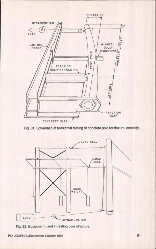
Pole testing is used to verify the de-sign and quality of production of thepoles. A test frame such as that shown inFigs. 28 and 31 is used. Here, the butt ofthe pole is fixed and the pole is pulledfrom a point below the tip, usually 2 ft(0.6 in), about a reaction point ground-line distance from the butt. By addingthe load in increments of the ultimatedesign, the cracking moment and physi-cal behavior of the pole to destructioncan he checked. It is good practice toinclude in the specifications some ran-dom pole testing to a percentage of theultimate strength of the pole as a qual-ity assurance check. A pole can be tested
PC[ JOURNAL/September-October 1984 77

v00
Table 3. Materials used for manufacturing prestressed concrete poles.
Concrete Prestressing steel Nonprestressed steelCompressive Ultimate Compressivestrength, psi strength, psi strength, psi
County (MPa) Type Type (MPa) Section and shape Type (MPa)Czechoslovakia 7100 Normal ST 140/175 250,000 V4 in. (6 mm)
(50) concrete (1716) RoundFrance 5500-8500 Normal ST 140/160 230,000 Plain
(40-60) concrete (1569) round
0.03-0.062 in.sEast Germany 6400-8500 Normal ST 1401175 230,000 (20-40 mm2 ) Deformed 57000-71000
(45-60) concrete (1569) Deformed oval ST III (392-490)
0.03-0.06 in.'West Germany 4200-10000 Normal ST 140/175 230,000 (20-40 mm 2 ) Deformed 57000-71000
(30-69) concrete (1569) Deformed oval ST 11I (392-490)
4a-fie in.India 6000-7500 Normal Indented and 230,000-255.000 (3.25-4.5 mm)
(42-52) concrete plain round (1569-1765) Indented andplain round
5/18 k8 in.Japan 7100 Normal J15G3109 193,000 (8-16 mm)
(88) concrete (1334) Bound deformed
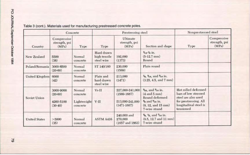
Table 3 (cont.). Materials used for manufacturing prestressed concrete poles.
Concrete Prestressing steel Nonprestressed stecl
Compressive Ultimate Compressivestrength, psi strength, psi strength, psi
Country (MPa) Type Type (MPa) Section and shape Type (MPa)
Hard drawn V1€-Y2 in.
New Zealand 5500 Normal high tensile 192,000 (5-12,7 mm)(38) concrete steel wire (1373) Round
Poland/Romania 3000-8500 Normal ST 1401160 230,000 Plain round(20-60) concrete (1569)
United Kingdom 6000 Normal Plain and 213,000 Ne, Otis, and "tiin.(42) concrete hard drawn (1471) (3.25, 4.5, and 7 mm)
steel wire
3000-900 Nonrial Vr-II 227,0011-241,000 '/a2, and ili a in. Hot rolled deformed(20-60) concrete (1569-1667) (4 and 5 mm) bars of low stressed
Soviet Union Round deformed steel are also used4260-5100 Lightweight V-II 213,000-241,000 % and ghs in. for prestressing. All(30-40) concrete (1471-1667) (9, 12, and 15 mm) longitudinal steel is
7-wire strand tensioned
240,000 and 's, '/s, and The in.United States >5000 Normal ASTM A416 270,000 (9.5, 12.7 and 11 mm)
(35) concrete (1657 and 1863) 7-wire strand
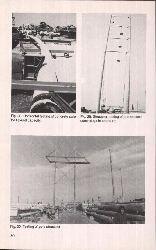
Fig. 28. Horizontal testing of concrete polefor flexural capacity.
Fig. 29. Structural testing of prestressedconcrete pole structure.
Fig. 30. Testing of pole structure.
so
. nnn rd i
E
FLECTION
DYNAMOMETER2'
LOAD
ti
REACTION ' 4-WHEEL wFRAMF DOLLY
Ui/f (FRJCTION) LiJO ma
^n vL/\
REACTION Il(SLIP AT POLE }—
WJ47QIik
a
-- REACTIONRSLIP)
CONCRETE SLAB
Fig. 31. Schematic of horizontal testing of concrete pole for flexural capacity.
LOAD _ _ aDYNRMOMETER
Fig. 32. Equipment used in testing pole structure.
PCI JOURNAUSepternber-October 1984 81
m
O O— O O
UNDER 100 FT LONGI -SOFT
ID
O O O O O O
1 15-25F1 LI5-a5FTOVER IOO FT. LONG
a E^
CENTER OF E^GRAVITY ^j'6 ^F^
UNDER 80 FT LONG OVER 80 FT LONG
Fig. 33. Truck loading data and handling lifting points of pole.
up to 90 percent of ultimate, and whenthe load is released, show no effect ofthe loading.
Structure testing is the simulation ofthe structure as it is to be used, loaded inincrements to its design loadings, in astatic condition (Figs. 29, 30, 32), tocheck its structural strength and be-havior.
HANDLINGTRANSPORTATION
AND ERECTIONAlthough prestressed concrete poles
are resilient and resist cracking, they re-quire special care in handling, trans-
porting and erecting. Some guidelinesfor safe handling of prestressed concretepoles are:
1. Always handle prestressed con-crete poles with the major axis inthe horizontal direction, with atwo-point balanced pickup.
2. While unloading from trucks, rail-road cars or waterway barges,handle the poles gently. Under nocircumstances should they bethrown onto a pile (Figs. 33 and34).
3. Poles should he stacked level andsupported so their own deadweight will not cause them to sag,
4. While transporting by pole trailer
82

Fig. 34. Railroad transportation of poles.
^ i a
Fig. 35. Truck transportation of pole.
(Fig. 35), the poles should he heldas rigid as possible to keep themfrom oscillating, which could causethem to crack. The use of a strong-back is suggested, if necessary.
5. When erecting single poles, it issuggested that they be rigged asshown in Figs. 36 and 37.
6. H-frame structures should be as-sembled and lifted with the use ofa spreader bar. With structuresover 80 ft (24 m), a second pickpoint should be used to get thepole butts off the ground whenlifting the structure to the verticalposition (Fig. 38).
PCI JOURNAUSeptember-October 1984 83
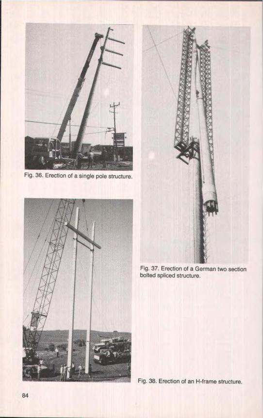
Fig. 36. Erection of a single pole structure.
Fig. 37. Erection of a German two sectionbolted spliced structure.
Fig. 38. Erection of an H-frame structure.
84
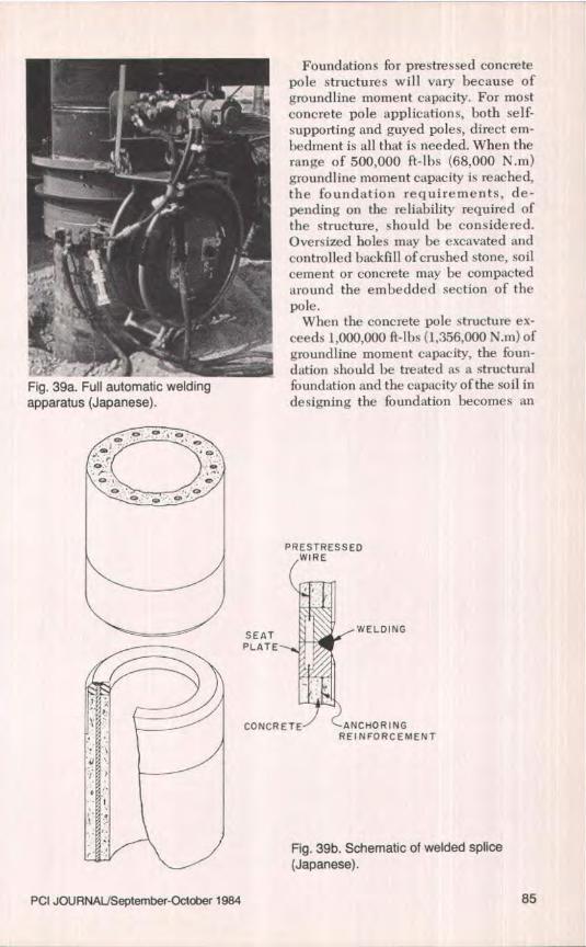
Fig. 39a. Full automatic weldingapparatus (Japanese),
Foundations for prestressed concretepole structures will vary because ofgroundline moment capacity. For mostconcrete pole applications, both self-supporting and guyed poles, direct em-bedment is all that is needed. When therange of 500,000 ft-lbs (68,000 N.m)groundline moment capacity is reached,the foundation requirements, de-pending on the reliability required ofthe structure, should be considered.Oversized holes may be excavated andcontrolled backfill of crushed stone, soilcement or concrete may be compactedaround the embedded section of thepole.
When the concrete pole structure ex-ceeds 1,000,000 ft-lbs (1,356,000 N.m) ofgroundline moment capacity, the foun-dation should he treated as a structuralfoundation and the capacity of the soil indesigning the foundation becomes an
PRESTRESSEDWIRE
SEAT WELDING
PLATE
CONCRETE ANCHORINGREINFORCEMENT
Fig. 39b. Schematic of welded splice(Japanese).
PCI JOURNAL`September-October 1984 85
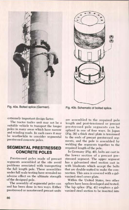
Fig. 40b. Schematic of bolted splice.
J
Fig. 40a. Bolted splice (German).
extremely important design factor.The tractor trailer unit may not be a
suitable vehicle to transport the longerpoles in many areas which have narrowacid winding roads. In such cases it maybe worthwhile to consider segmentalprestressed concrete poles.
SEGMENTAL PRESTRESSEDCONCRETE POLES
Prestressed poles made of precastsegments assembled at the site avoidproblems associated with transportingthe full length pole. These assembliesunder full scale testing have revealed noadverse effect on the ultimate strengthof the designed pole.
The assembly of segmental poles canand has been done in two ways. Eitherprestressed or nonstressed precast units
are assembled to the required polelength and post-tensioned or precastprestressed pole segments can bespliced in one of four ways. In Japan(Fig. 39) a thick steel plate is tensionedto the ends of precast prestressed seg-ments, and the pole is assembled bywelding the segments together to therequired length of the pole.
In Germany (Fig. 40), bolts are cast inthe lower section of a precast pre-stressed segment. The upper segmenthas a galvanized steel section cast inwith blockouts which accept the boltsthat are double-nutted to make the con-nection. This area is covered with a gal-vanized steel cover plate.
Within the United States, two othersplices have been developed and tested.The lap splice (Fig. 41) employs a gal-vanized steel section to be inserted into
86
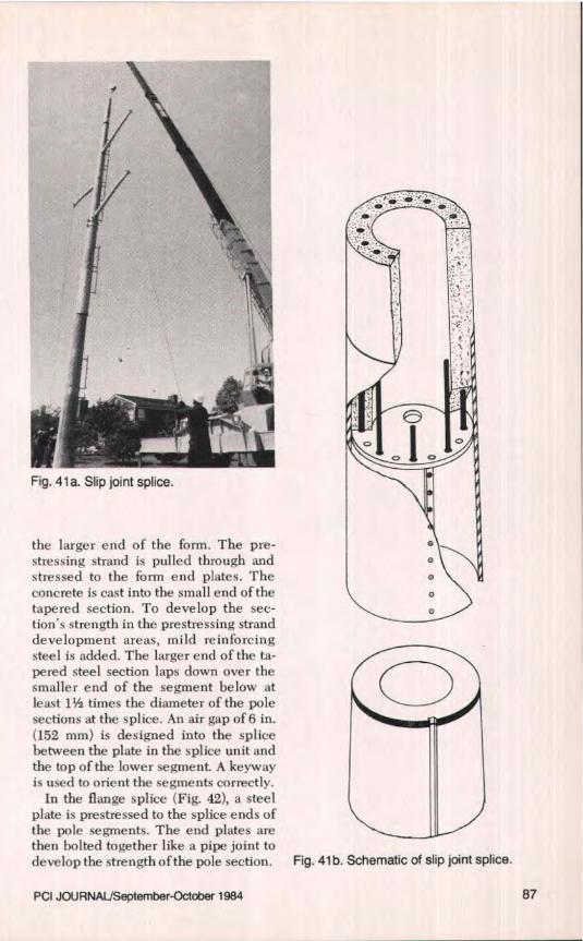
Fig. 41 b. Schematic of slip joint splice.
Fig. 41 a. Slip joint splice.
the larger end of the form, The pre-stressing strand is pulled through andstressed to the form end plates. Theconcrete is cast into the small end of thetapered section. To develop the sec-tion's strength in the prestressing stranddevelopment areas, mild reinforcingsteel is added. The larger end of the ta-pered steel section laps down over thesmaller end of the segment below atleast 1% times the diameter of the polesections at the splice. An air gap of 6 in.(152 mm) is designed into the splicebetween the plate in the splice unit andthe top of the lower segment. A keywayis used to orient the segments correctly.
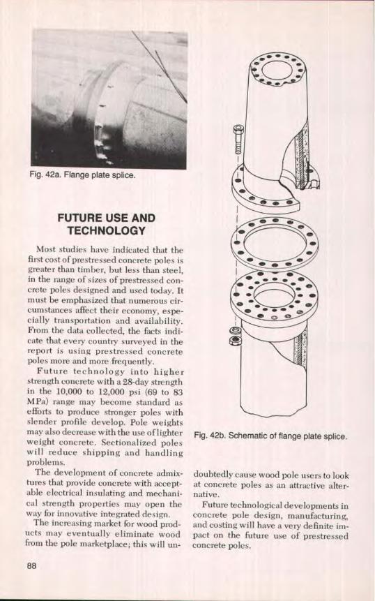
In the flange splice (Fig. 42), a steelplate is prestressed to the splice ends ofthe pole segments. The end plates arethen bolted together like a pipe joint todevelop the strength of the pole section.
PCI JOURNAL/September-October 1984 87
t k-
Fig. 42a. Flange plate splice.
FUTURE USE ANDTECHNOLOGY
Most studies have indicated that thefirst cost of prestressed concrete poles isgreater than timber, but less than steel,in the range of sizes of prestressed con-crete poles designed and used today. itmust be emphasized that numerous cir-cumstances affect their economy, espe-cially transportation and availability.From the data collected, the facts indi-cate that every country surveyed in thereport is using prestressed concretepoles more and more frequently.
Future technology into higherstrength concrete with a 28-day strengthin the 10,000 to 12,000 psi (69 to 83MPa) range may become standard asefforts to produce stronger poles withslender profile develop. Pole weightsmay also decrease with the use of lighterweight concrete. Sectionalized poleswill reduce shipping and handlingproblems.
The development of concrete admix-tures that provide concrete with accept-able electrical insulating and mechani-cal strength properties may open theway for innovative integrated design.
The increasing market for wood prod-ucts may eventually eliminate woodfrom the pole marketplace; this will un-
• • s
o - • •\s ue• . • .^
Fig. 42b. Schematic of flange plate splice.
doubtedly cause wood pole users to lookat concrete poles as an attractive alter-native.
Future technological developments inconcrete pole design, manufacturing,and costing will have a very definite im-pact on the future use of prestressedconcrete poles.
88
SELECTED REFERENCES
1. Aheles, P. W., "Impact Resistance ofPrestressed Concrete Masts," 5th Con-gress, International Association forBridge & Structural Engineering, Lis-bon, Portugal, 1957.
2. Amin, ]. M., "Prestressed Concrete Fac-tory at Vallabh Vidyanagar-Manufac-ture of Transmission Line Poles," IndianConcrete Journal, May 1959,
3. Axtell, H. D., "Concrete Pole Met Cost,Appearance Requirements," ElectricLight dr Power, April 1969.
4. Axtell, H. D., "Concrete TransmissionTowers Blend With Rugged Scenery,"Electrical World, September 2, 1963.
5. Axteli, H. D., "Prestressed ConcreteH-Frame Transmission Towers," E & 0Section NWPPA, Tacoma, Washington,1963.
6. "Bright Prospects for Concrete LightPoles," Concrete Products, November1966.
7. "Concrete Poles Are Placed in ConcreteCylinders to Build Line Over SaltWater," Transmission and Distribution,October 1967.
8. "Concrete Poles Require No Make-Up,"The American City, March 1957.
9. Commack, H. W., "Notes on PrestressedPoles," New Zealand Engineering, June15, 1952.
10.Cormack, H. W., "'Precast Concrete forPrestressing With Special Reference toConcrete Poles," New Zealand Engi-neering, February 15, 1953.
11. "Costa Rica Has Tallest Precast ConcreteTowers," Civil Engineering, March1961.
12. Crisp, C. F. C., "A Survey of ConcreteTransmission Line Poles," ConstructionReview, December 1955, Australia.
13. "Design of Reinforced Concrete Trans-mission Line Pole," Indian ConcreteJournal, December 15, 1974.
14. "Detailed Static Calculation of Pre-stressed Concrete Poles," Betonstein-zeitung, June 1964, German,
15. Dmitriex, S., "General Report on Pre-stressed Concrete Poles," FIP Sympo-sium on Mass-Produced Prestressed Pre-cast Elements, Madrid, June 1968-
16. "Prestressed Concrete Pole Transmis-sion," Eugene Water and Electric Board,February 10, 1970.
17. "Floodlighting Towers," ACI journal,March 1958.
18. George, Z., and Sethuraman, N., "Par-tially Prestressed Concrete Poles-ANew System of Manufacture Using HighStrength Deformed Bars and PortableStressing Beds," Indian Concrete Jour-nal, October 1975.
19. George, Z., Swaminathan, K. V., Dayarat-ram, P-, and Salvi, K. G., 'PrestressedConcrete Poles-State of the Art," Inter-national Seminar on Prestressed Con-crete Poles, Pipes & Pressure Vessels,Madras, India, 1972.
20. "Germany's Centrifugal ConcretePoles," Concrete, November 1955,
21. Ghosh, R. J., and Jenkins, G. A., "LoadTesting of Prestressed Concrete Trans-mission Pole and Its Concrete Footing,"Ontario Hydra Research Quarterly, FirstQuarter, 1977.
22. "Grandview No Longer a Tunnel," TheAmerican City, November 1960.
23. Grzezorzewski, W., "Prestressed Con-crete Poles in Poland," FIP Symposiumon Mass-Produced Prestressed PrecastElements, Madrid, June 1968.
24. "Interest in Concrete Poles Increases,"Electrical World, V. 184, No. 12, Decem-ber 15, 1975.
25. Ironman, R., "Spinning Molds Form Pre-stressed Concrete Lamp Standards,"Concrete Products, June 1958.
26. Ismael, N. F., "Concrete Pole TestFoundation Instrumentation and Test-ing," Stress-Crete Ltd., Ontario HydroResearch Division, Report No. 740-624-199-3303, January 6, 1976.
27. King, C. F., "Vepco's 230 kV Single Cir-cuit Line Using Spliced Concrete Poles,"Virginia Electric and Power Company,Richmond, Virginia.
28. MacCarthy, H. P., "Concrete Pole De-sign & Applications," Edison ElectricInstitute, Transmission and DistributionCommittee, Seattle, Washington, Octo-ber 3-4, 1974.
29. Mhatre, R. P., "Prestressed ConcretePoles for Power Transmission Lines,"Indian Concrete Journal, August 1959.
30. "Concrete Poles for 110 kV Aerial PowerTransmission Lines," Pfleiderer Con-sulting CMBH, Neumarkt/OPF.
31. Pilsbury, W. L., "Prestressed Concrete
PCI JOURNAL/September-October 1984 89
Hurricane-Proofs 230 kV Line," Electri-cal World, July 1, 1963.
32. "Precast Concrete Lighting Columns,"Concrete Building & Concrete Products,V. 28, No. 1, January 1953.
33. "Prestressed Concrete Carriers power ofthe Future," PCltems, V. 7, No, 8, August1961.
34. "Prestressed Concrete Poles Need NoFooting," Electrical World, January 19,1970, p. 37.
35. "Prestressed Concrete Poles Prove Prac-tical," Electrical World, V. 174, No, 11,December 1970.
36. "P.S.I. Test Concrete Pole, DesignLimits Exceeded," Electric Light &Power, January 1979.
37. Price, B., "Prestressed Concrete—It'sRole in Beautility," Utilities AppearanceCommittee Meeting, Phoenix, Arizona,January 12, 1967.
38. Rodgers, T. E., Jr., "Developing Pre-stressed Concrete Poles," ElectricalSouth, February 1971.
39. Rodgers, T. E., Jr., "A Utility's Devel-opment and Use of Prestressed ConcretePoles," Southeastern Electric Exchange,Engineering & Operations Division,Transmission Section, Hollywood,Florida, October 16, 1970. Also pub-lished in PC! JOURNAL, V. 17, No 3,May-June 1972, pp. 8-13.
40. Rodgers, T. E., Jr., "Vepco's Design andUse of Prestressed Concrete Poles,"Canadian Electrical Association, Trans-mission Sections, Winnepeg, Manitoba,Canada, September 24, 1974; South-eastern Electrical Engineering & Oper-ation Division, Transmission Sections,New Orleans, Louisiana, April 26, 1976;Pennsylvania Electric Association,Transmission & Distribution Committee,Engineering Section, Pittsburgh,Pennsylvania, January 26, 1977.
41. Rodgers, T. E., Jr., Anderson, W. C., andChange, D. R., "Guide fnr Design andSpecifications for Concrete. Pole Struc-tures, IEEE Committee Report, Trans-action Paper, V. PAS-94, No. 4, July-August 1975.
42. Rodgers, T. E., Jr., and Riley, D. L.,"Prestressed and Post-Tensioned Con-crete Structures," Transmission & Dis-tribution, December 1973.
43. Rosam, M. E., "Hurricane Rip At KeyWest New 69 kV Line Overhead andWater," Electrical World, November 17,1963.
44. Ruckhaus, F., "Prestressed ConcreteTransmission Line Structure,"Jou rnal ofthe Power Division, Proceedings,American Society of Civil Engineers, V.94, No, P-01, May 1968.
45. Schupack, M., and McDonald, A., "Expe-rienced Transmission Tower of Pre-stressed Concrete," Civil Engineering,August 1961.
46. Schupack, M., "Design of an Extra-HighVoltage Transmission Tower 100 FeetHigh," PCI JOURNAL, V. 7, No. 1, Feb-ruary 1962, pp. 32-46.
47. "Sectional Concrete Pole Design EasesT-Line Construction Problems," ElectricLight & Power, September 1978.
48. "Simplified Method for Static Calcula-tion of Prestressed Concrete Poles," Be-tonsteinzeitung, February 1964 (in Ger-man).
49. "Spun Concrete Poles to be Made by St.Louis Finn," Traffic Engineering, March1959.
50. "Spun Lighting Columns," ConcreteBuilding and Concrete Products, May1959.
51. "110 kV Transmission Poles," Construc-tional Review, V. 45, No. 2, May 1972.
52. Vondrasek, Jaroslav, "Production of Pre-stressed Concrete Poles," Inzenyrska5tavby, 1974.
53. Woodson, L. V., and Whitlow, J. C.,"Poles Designed to Provide Clearancefor Conversion," Electrical World, De-cember 19, 1966-
54. Woodson, L. V., "Spun Concrete PolesShow Favorable T&D Potential,"Transmission & Distribution, July 1968.
55. Wright, C. E., ` Prestressed ConcretePoles," Concrete Products, September1955.
56. PCI Committee on Prestressed ConcretePoles, "Guide Specification for Pre-stressed Concrete Poles," PCI JOUR-NAL, V. 27, No. 3, May-June 1982, pp.18-29.
57. PCI Committee on Prestressed ConcretePoles, "Guide Design for PrestressedConcrete Poles," PCI JOURNAL, V. 28,No. 3, May-June 1983, pp. 22-87.
f
•d
SPECIFICATIONS/ STANDARDS1. BPA Specification for PrestressedConcrete
Transmission Structures, BonnevillePower Association, December 1972.
2. BS 607, 1960 Specification for ConcretePoles for Electrical Transmission andTraction Systems, British Standard In-stitution, 1960.
3. CSA Standard A14-M-Concrete Poles,Third Draft Proposed, Canadian Stan-dards Association, May 1978,
4. DIN 4228, Prestressed Concrete Mast,Regulation for Design and Manufacture,Lerman Norms, October 1964.
5. EIA-RS-222-C, Electronic Industries As-sociation Standard, March 1960.
6. IS: 1678-1978, Indian Standard Specifi-cation for Prestressed Concrete Poles forOverhead Power, Traction and Tele-communication Lines, Indian StandardsInstitution, New Delhi, August 1979.
7. IS: 2193-1962, Indian Standard Specifi-cation for Prestressed Concrete StreetLighting Columns, Indian Standards In-stitution, New Delhi, January 1963.
8. IS: 2905-1966, Indian Standard Methodsof Test for Concrete Poles for OverheadPower and Telecommunication Lines,Indian Standards institution, New Delhi,June, 1966.
9. IS: 7321-1974, Indian Standard, Code ofPractice for Selection, Handling andErection of Concrete Poles for OverheadPower and Telecommunication Lines,Indian Standard Institution, New Delhi,
September 1974.10. JIS A5309-1977, Pretensioned and Re-
inforced Spun Concrete Poles, JapaneseIndustrial Standard, 1971.
11. National Electrical Safety Code, ANSIC2, 1977 Edition.
12. NZS 1054-1966, Concrete Poles forElectrical Transmission, Standards As-sociation of New Zealand, November1966.
13. prEN 40, Draft 2, Lighting Columns,Special Requirements for Reinforcedand Prestressed Concrete LightingPoles, CEN European Committee forStandardization, Central Secretariat: RueBrederode, 2, B-1000 Brussels, Part 9,Edition 1, June 1979.
14. Standard Specification for StructuralSupports for Highway Signs, Luminairesand Traffic Signals, AASHTO Subcom-mittee on Bridges and Structures, 1975.
15. 8-2101, Specification for PrestressedConcrete Poles, Standards OverheadTransmission lines, Florida Power &Light Co., November 1973.
16. PCI Committee on Prestressed ConcretePoles, "Guide Specification for Pre-stressed Concrete Poles," PCI JOUR-NAL, V. 27, No. 3, May-June 1982, pp.18-29.
17. PCI Committee on Prestressed ConcretePoles, "Guide Design for PrestressedConcrete Poles," PCI JOURNAL, V. 28,No. 3, May-June 1983, pp. 22-87.
w
NOTE: Discussion of this paper is invited. Please submityour comments to PCI Headquarters by May 1, 1985.
PCI JOURNAUSepternber-October 1984 91

COMPANY BROCHURES (AMERICAN-CANADIAN)
1. American Concrete Lighting Poles &Stress-Spun Concrete Lighting Stan-dards, Union Metal Manufacturing Co.,P.O. Box 308, East Stroudsburg, Penn-sylvania 18301.
2. Centrifugally Cast, Prestressed ConcretePoles, Bayshore Concrete Products Cor-poration, P.O. Box 230, Cape Charles,Virginia 23310.
3. Concrete Lighting Poles, Ameron, PoleProducts Division, P.O. Box 755, 1020"B" Street, Fillmore, California 93015.
4. Concrete Poles, Sherman Utility Struc-tures, Inc., 3735 32nd Avenue, Tusca-loosa, Alabama 35406,
5. Inficrete Poles, Barratt Spun ConcretePoles Ltd., P.O. Box 372, 4536 Mont-rose Road, Niagara Falls, Canada L2E6T8.
6. Precast Prestressed Concrete Poles,Genstar Structures Limited, Pole Divi-
sion, 1000 Alberta Place, 1520-4thStreet S.W., Calgary, Alberta T2R 1H5,Canada.
7. Prestressed Concrete Poles, AmericanPrecast Concrete, Inc., 1030 South KitleyAvenue, Indianapolis, Indiana 46203.
8. Prestressed Concrete Poles, Power SpanInc., P.O. Box 1056, Hayfield, Minnesota55940.
9. Prestressed Concrete Poles, The CretexCompanies, Inc., 311 Lowell Avenue,Elk River, Minnesota55330.
10. Prestressed Concrete Products, ConcretePoles, Dura-Stress Inc., P.O. Box 779,Leesburg, Florida 32748.
11. Prestressed Concrete, TransmissionPoles, REM-Co Products, Inc., P.O. Box7, Hayfield, Minnesota 55940.
12. Prestressed Concrete TransmissionStructures, Contran, P.O. Box H, Osseo,Minnesota 55369.
COMPANY BROCHURES (EUROPEAN)
1. Beleuchtungsrnaste, SACAC, Buro,Zurich, Switzerland.
2. Beton, N. V. Cobefa Zolder, Brussels,Belgium.
3. Centrifugal Concrete Machinery, Cen-tricon, Bonn, West Germany.
4. Concrete Utilities Limited, Ware,Herts, England,
5. Dainichi Concrete Industry Co., Ltd.,Nagoya, Japan.
6- Di' positif de Seeurite le Bag, Cram SA,Villeneuve, France.
7. L'Eclairage du Reseau, Routier Beige,Catalogue Pernament Industrie duBeton.
8. Ligne Normalisee 132 kV, Liste desMats ET, Calculs Statiques, Gram SA,Villeneuve, France.
9. Liste des Adherents, Federation Fran-caise de l'Industrie du Beton, France.
10. NC Poles, Spun Concrete Poles, Nip-
pon Concrete Industries Co., Ltd.,Tokyo, Japan.
11. Normalmaste fiir 50-kV-Leitungen,SACAC, Buro, Zurich, Switzerland,
12. Pfleiderer Consulting GMBH, New-marketlOPF, West Germany.
13. Poteauz d'Eclairage Public, Comit6Electrotechnique Beige, Brussels, Bel-gium.
14a- Prestressed Concrete TransmissionPoles. Stanton & Stave ley, British SteelCorp., Nottingham, England.
14b. Prestressed Spun Concrete LightingColumns, Stanton & Staveley, BritishSteel Corp., Nottingham, England.
15. Reinforced Concrete Poles, StefanWestberg, MSc, VAXJO, Sweden.
16. SA des BPtons Centrifuges Lenzbourg,Cram SA, Villeneuve, France.
17. Spun Reinforced Concrete, FratelliCarrara S.N.C., Vicenza, Italy.
92

APPENDIXPRESTRESSED CONCRETE POLE APPLICATIONS
Fig. A1. Flag pole. Fig. A2. Area lighting.
Fig. A3. Area lighting.
PCI JO1J NALJSeptember-October 1984 93
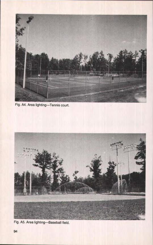
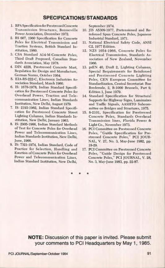
Fig. A4. Area lighting—Tennis court.
Fig. A5. Area lighting—Baseball field.
94
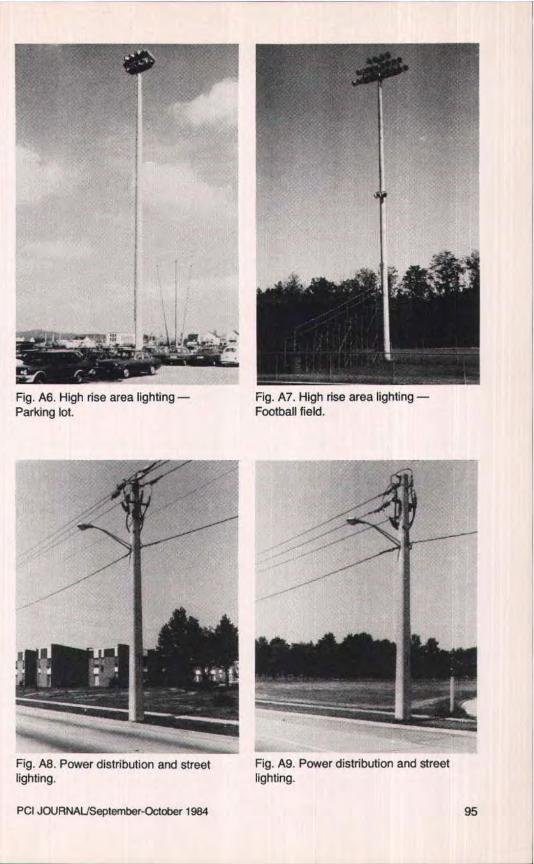
Fig. A6. High rise area lighting —Parking lot.
Fig. A7. High rise area lighting —Football field.
Fig. A8. Power distribution and streetlighting.
Fig. A9. Power distribution and streetlighting.
PCI JOURNAL/September-October 1984 95
Fig. A10. Power distribution and streetlighting.
Fig. Al1. Power distribution and streetlighting.
Fig. Al2. Power transmission with Fig. A13. Power transmission withdistribution underbuiId and area lighting, distribution underbuild.
96

II I!
Fig. A14. European power transmission. Fig. A15. European power transmission.
Fig. Al 6. Close-up of European power transmission.
PC JOURNAL/September-October 1984 97

1
Fig. A17. European power transmission.
Fig. Al B. Power transmission. Fig. A19. Power transmission.
98
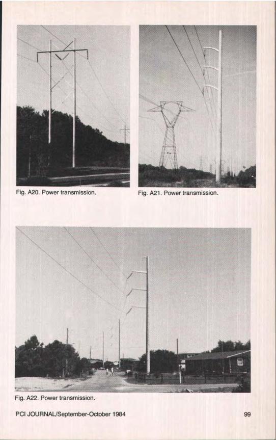
A ^ ^
Fig. A20. Power transmission. Fig. A21. Power transmission.
Fig. A22. Power transmission.
PCI JOURNAL/September-October 1984 99
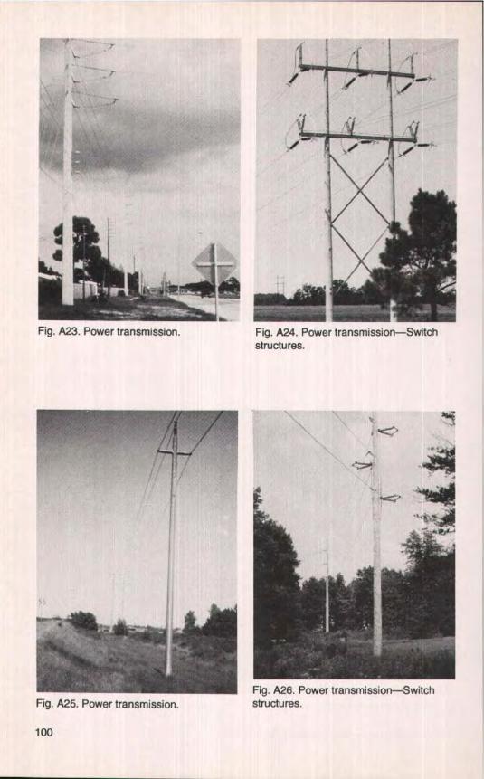
Fig. A25. Power transmission.Fig. A26. Power transmission—Switchstructures.
r
_Fig. A23. Power transmission. Fig. A24. Power transmission—Switch
structures.
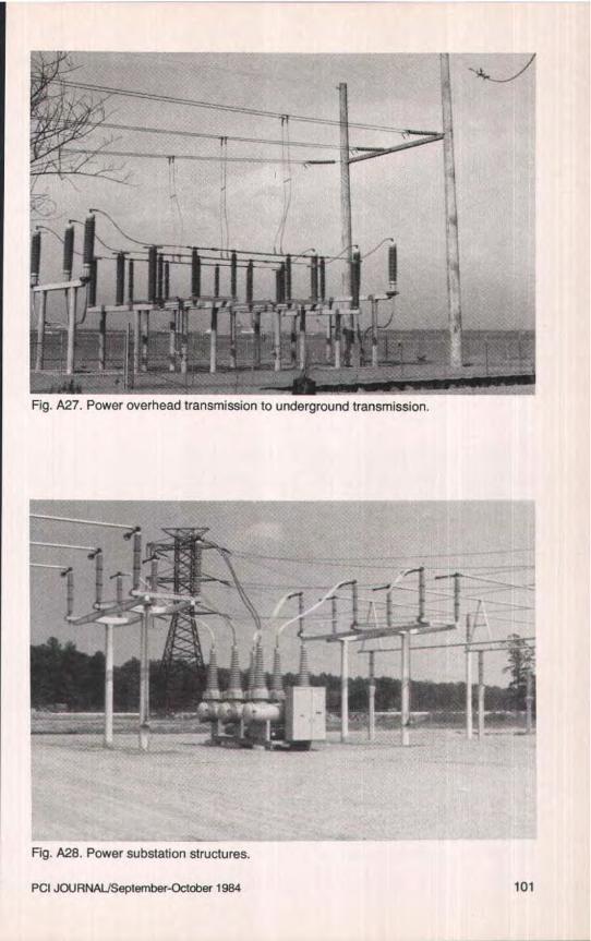
Fig. A27. Power overhead transmission to underground transmission.
Fig. A28. Power substation structures.
PCI JOURNAL/September-October 1984
101
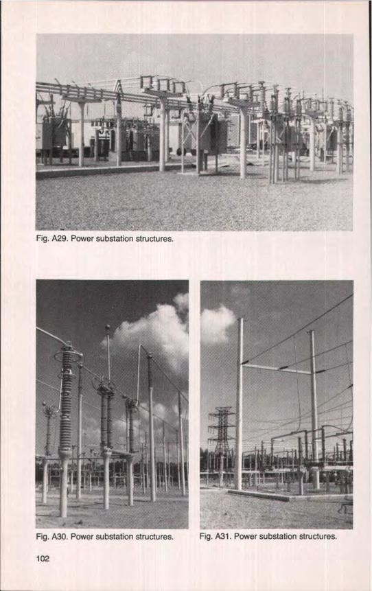
Fig. A29. Power substation structures.
Fig. A30. Power substation structures, Fig. A31. Power substation structures.
102
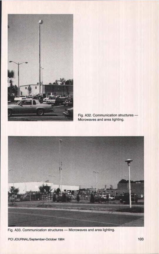
Fig. A32. Communication structures -Microwaves and area lighting.
F
Fig. A33. Communication structures — Microwaves and area lighting_
PCI JOURIVAL)September-October 1984 103