Embed Size (px)
Citation preview
prestigeSolo 60Solo 175Solo 250Solo 399Water Boiler
Warranty Registration Card must be filled out by the customer and mailed within thirty (30) days of installa-
tion in order to gain warranty coverage.
When receiving the PRESTIGE Solo unit, any claims for damage or shortage in shipment must be filed
immediately against the transportation company by the consignee.
Leave all documentation received with appliance with owner for future reference.
* I N S T A L L A T I O N A N D M A I N T E N A N C E * * I N S T A L L A T I O N A N D M A I N T E N A N C E *
M A N U A LM A N U A L
2011-50 Manual Prestige 60/175/250/399_TriMax_Revised 3/7/13
If the information in this manual is not followed exactly, a fire or explosion may
result causing property damage, personal injury or death.
FOR YOUR SAFETY
• Do not store or use gasoline or other flammable vapors and liquids in the vicinity ofthis or any other appliance.
• WHAT TO DO IF YOU SMELL GAS
- Do not try to light any appliance- Do not touch any electrical switch; do not use any phone in your building.- Immediately call your gas supplier from a neighbor’s phone. Follow the gas
supplier’s instructions.- If you cannot reach your gas supplier, call the fire department.
Installation and service must be performed by a qualified installer, service agency or thegas supplier.
L I S T E D
WARNING
NOTICE
Table of Contents
i
PRODUCT AND SAFETY INFORMATION
Definitions. . . . . . . . . . . . . . . . . . . . . . . . . . . . . . . . . . . . . . . . . . . . . . . . . . . 1
Product and Safety Information . . . . . . . . . . . . . . . . . . . . . . . . . . . . . . . . . . 2
SECTION I - PRE-INSTALLATION ITEMS
Code Compliance . . . . . . . . . . . . . . . . . . . . . . . . . . . . . . . . . . . . . . . . . . . . . 3
Determining Product Location . . . . . . . . . . . . . . . . . . . . . . . . . . . . . . . . . . . 3
Boiler Replacement. . . . . . . . . . . . . . . . . . . . . . . . . . . . . . . . . . . . . . . . . . . . 3
Recommended Clearances . . . . . . . . . . . . . . . . . . . . . . . . . . . . . . . . . . . . . . 3-4
Residential Garage Installations . . . . . . . . . . . . . . . . . . . . . . . . . . . . . . . . . 4
Boiler Freeze Protection Feature . . . . . . . . . . . . . . . . . . . . . . . . . . . . . . . . . 4
SECTION II - COMBUSTION AIR AND VENTING
Combustion Air Contamination . . . . . . . . . . . . . . . . . . . . . . . . . . . . . . . . . . 5
Ventilation and Combustion Air Requirements - Direct Vent . . . . . . . . . . . 6
Ventilation and Combustion Air Requirements - Category IV . . . . . . . . . . 6
Methods of Accessing Combustion Air into a Space - Category IV . . . . . . 7
- Indoor Combustion Air. . . . . . . . . . . . . . . . . . . . . . . . . . . . . . . . . . 7
- Outdoor Combustion Air . . . . . . . . . . . . . . . . . . . . . . . . . . . . . . . . 7-8
- Combination of Indoor and Outdoor Combustion Air. . . . . . . . . . 9
Combustion Air and Vent Piping . . . . . . . . . . . . . . . . . . . . . . . . . . . . . . . . . 9
Removal of an Existing Boiler from a Common Vent System . . . . . . . . . . 10
Commonwealth of Massachusetts Installation . . . . . . . . . . . . . . . . . . . . . . . 11
SECTION III - UNIT PREPARATIONS
Handling Instructions . . . . . . . . . . . . . . . . . . . . . . . . . . . . . . . . . . . . . . . . . . 12
Wall Mounting Installation . . . . . . . . . . . . . . . . . . . . . . . . . . . . . . . . . . . . . . 12
Wall Mounting Guidelines . . . . . . . . . . . . . . . . . . . . . . . . . . . . . . . . . . . . . . 12
Wall Bracket Installation - Stud Walls . . . . . . . . . . . . . . . . . . . . . . . . . . . . . 13
Wall Bracket Installation - Solid Walls . . . . . . . . . . . . . . . . . . . . . . . . . . . . 13
Boiler Mounting . . . . . . . . . . . . . . . . . . . . . . . . . . . . . . . . . . . . . . . . . . . . . . 13
SECTION IV - BOILER PIPING
General Piping Requirements . . . . . . . . . . . . . . . . . . . . . . . . . . . . . . . . . . . . 14
Pressure Relief Valve . . . . . . . . . . . . . . . . . . . . . . . . . . . . . . . . . . . . . . . . . . 14
Low Water Cut Off Device. . . . . . . . . . . . . . . . . . . . . . . . . . . . . . . . . . . . . . 14
Additional Limit Control . . . . . . . . . . . . . . . . . . . . . . . . . . . . . . . . . . . . . . . 16
Backflow Preventer. . . . . . . . . . . . . . . . . . . . . . . . . . . . . . . . . . . . . . . . . . . . 16
Table of Contents
ii
Boiler System Piping Applications. . . . . . . . . . . . . . . . . . . . . . . . . . . . . . . . 16
Expansion Tank and Makeup Water . . . . . . . . . . . . . . . . . . . . . . . . . . . . . . . 16-17
Diaphragm Expansion Tank . . . . . . . . . . . . . . . . . . . . . . . . . . . . . . . 17
Closed-Type Expansion Tank . . . . . . . . . . . . . . . . . . . . . . . . . . . . . . 17
Circulator . . . . . . . . . . . . . . . . . . . . . . . . . . . . . . . . . . . . . . . . . . . . . . . . . . . 17
Sizing Primary Piping. . . . . . . . . . . . . . . . . . . . . . . . . . . . . . . . . . . . . . . . . . 17
Domestic Hot Water System Piping . . . . . . . . . . . . . . . . . . . . . . . . . . . . . . . 17
System Piping - Zone Circulators. . . . . . . . . . . . . . . . . . . . . . . . . . . . . . . . . 17
System Piping - Zone Valves . . . . . . . . . . . . . . . . . . . . . . . . . . . . . . . . . . . . 17
Piping Component Legend . . . . . . . . . . . . . . . . . . . . . . . . . . . . . . . . . . . . . . 18
Near Boiler Piping Diagrams . . . . . . . . . . . . . . . . . . . . . . . . . . . . . . . . . . . . 19
System Piping - Through Boiler. . . . . . . . . . . . . . . . . . . . . . . . . . . . . . . . . . 20
System Piping - Radiant Heating . . . . . . . . . . . . . . . . . . . . . . . . . . . . . . . . . 20
System Piping - Special Applications. . . . . . . . . . . . . . . . . . . . . . . . . . . . . . 20
System Piping - Multiple Units Installation . . . . . . . . . . . . . . . . . . . . . . . . . 20
System Piping Diagrams. . . . . . . . . . . . . . . . . . . . . . . . . . . . . . . . . . . . . . . . 21-23
SECTION V - INSTALLING VENT / COMBUSTION AIR & CONDENSATE DRAIN
Installing Vent and Combustion Air . . . . . . . . . . . . . . . . . . . . . . . . . . . . . . . 24
Installing Condensate Drain Assembly. . . . . . . . . . . . . . . . . . . . . . . . . . . . . 24-25
SECTION VI - GAS PIPING
Gas Supply Piping Connection. . . . . . . . . . . . . . . . . . . . . . . . . . . . . . . . . . . 26
Natural Gas
Pipe Sizing -Natural Gas . . . . . . . . . . . . . . . . . . . . . . . . . . . . . . . . . 27
Natural Gas Supply Pressure Requirements. . . . . . . . . . . . . . . . . . . 27
Propane Gas
Pipe Sizing - Propane Gas . . . . . . . . . . . . . . . . . . . . . . . . . . . . . . . . 28
Propane Gas Supply Pressure Requirements . . . . . . . . . . . . . . . . . . 28
Gas Valve/Venturi Assembly . . . . . . . . . . . . . . . . . . . . . . . . . . . . . . 29
SECTION VII - INTERNAL WIRING
General Requirements. . . . . . . . . . . . . . . . . . . . . . . . . . . . . . . . . . . . . . . . . . 30
Fuse Locations . . . . . . . . . . . . . . . . . . . . . . . . . . . . . . . . . . . . . . . . . . . . . . . 30
Internal Factory Wiring Diagram . . . . . . . . . . . . . . . . . . . . . . . . . . . . . . . . . 31
SECTION VIII - EXTERNAL WIRING
Installation Compliance . . . . . . . . . . . . . . . . . . . . . . . . . . . . . . . . . . . . . . . . 32
Line Voltage Connections. . . . . . . . . . . . . . . . . . . . . . . . . . . . . . . . . . . . . . . 32
Circulator Wiring . . . . . . . . . . . . . . . . . . . . . . . . . . . . . . . . . . . . . . . . . . . . . 32-33
iii
Table of Contents
Alarm Wiring . . . . . . . . . . . . . . . . . . . . . . . . . . . . . . . . . . . . . . . . . . . . . . . . 33
Low Voltage Connections. . . . . . . . . . . . . . . . . . . . . . . . . . . . . . . . . . . . . . . 33
Thermostat Wiring . . . . . . . . . . . . . . . . . . . . . . . . . . . . . . . . . . . . . . . . . . . . 33-34
Outdoor Sensor Wiring . . . . . . . . . . . . . . . . . . . . . . . . . . . . . . . . . . . . . . . . . 34
Domestic Hot Water Wiring . . . . . . . . . . . . . . . . . . . . . . . . . . . . . . . . . . . . . 34
Additional Boiler Limits. . . . . . . . . . . . . . . . . . . . . . . . . . . . . . . . . . . . . . . . 34
External Modulation Control . . . . . . . . . . . . . . . . . . . . . . . . . . . . . . . . . . . . 34
System Sensor Wiring. . . . . . . . . . . . . . . . . . . . . . . . . . . . . . . . . . . . . . . . . . 34-35
Cascade Wiring . . . . . . . . . . . . . . . . . . . . . . . . . . . . . . . . . . . . . . . . . . . . . . . 35
Modbus Wiring . . . . . . . . . . . . . . . . . . . . . . . . . . . . . . . . . . . . . . . . . . . . . . . 35
Zone Valve Wiring . . . . . . . . . . . . . . . . . . . . . . . . . . . . . . . . . . . . . . . . . . . . 36
Zone Circulator Wiring. . . . . . . . . . . . . . . . . . . . . . . . . . . . . . . . . . . . . . . . . 37
System Piping Wiring Diagrams . . . . . . . . . . . . . . . . . . . . . . . . . . . . . . . . . 38-39
SECTION IX - TRIMAX OPERATION
TriMax User Interface . . . . . . . . . . . . . . . . . . . . . . . . . . . . . . . . . . . . . . . . . 40
TriMax Navigation . . . . . . . . . . . . . . . . . . . . . . . . . . . . . . . . . . . . . . . . . . . . 41
Trimax Menu Structure. . . . . . . . . . . . . . . . . . . . . . . . . . . . . . . . . . . . . . . . . 42
Home Screen. . . . . . . . . . . . . . . . . . . . . . . . . . . . . . . . . . . . . . . . . . . . . . . . . 43
Status Line Messages . . . . . . . . . . . . . . . . . . . . . . . . . . . . . . . . . . . . . . . . . . 44
Main Menu . . . . . . . . . . . . . . . . . . . . . . . . . . . . . . . . . . . . . . . . . . . . . . . . . . 45
EZ Setup Menu . . . . . . . . . . . . . . . . . . . . . . . . . . . . . . . . . . . . . . . . . . . . . . . 46
Heating EZ Setup . . . . . . . . . . . . . . . . . . . . . . . . . . . . . . . . . . . . . . . . . . . . . 46-47
Domestic Hot Water EZ Setup . . . . . . . . . . . . . . . . . . . . . . . . . . . . . . . . . . . 48-49
EZ Setup Reset . . . . . . . . . . . . . . . . . . . . . . . . . . . . . . . . . . . . . . . . . . . . . . . 49
Display EZ Setup . . . . . . . . . . . . . . . . . . . . . . . . . . . . . . . . . . . . . . . . . . . . . 49
CH/DHW Operation . . . . . . . . . . . . . . . . . . . . . . . . . . . . . . . . . . . . . . . . . . 50
Boiler Information . . . . . . . . . . . . . . . . . . . . . . . . . . . . . . . . . . . . . . . . . . . . 50
Information Items . . . . . . . . . . . . . . . . . . . . . . . . . . . . . . . . . . . . . . . . . . . . . 51
Lockout History . . . . . . . . . . . . . . . . . . . . . . . . . . . . . . . . . . . . . . . . . . . . . . 52
Lockout Screen . . . . . . . . . . . . . . . . . . . . . . . . . . . . . . . . . . . . . . . . . . . . . . . 53
Manual Reset Hard Lockouts . . . . . . . . . . . . . . . . . . . . . . . . . . . . . . . . . . . . 54
Automatic Reset Soft Lockouts . . . . . . . . . . . . . . . . . . . . . . . . . . . . . . . . . . 55
SECTION X - START-UP PREPARATION
Check Boiler System Water Chemistry
Water pH Level 6.0 to 8.0 . . . . . . . . . . . . . . . . . . . . . . . . . . . . . . . . 56
Water Hardness Less Than 7 Grains. . . . . . . . . . . . . . . . . . . . . . . . . 56
Chlorinated Water . . . . . . . . . . . . . . . . . . . . . . . . . . . . . . . . . . . . . . . 56
Flush Boiler System to Remove Sediment. . . . . . . . . . . . . . . . . . . . . . . . . . 56
Cleaning of Old Boiler/System. . . . . . . . . . . . . . . . . . . . . . . . . . . . . . . . . . . 56
iv
Table of Contents
Cleaning of New Boiler/System. . . . . . . . . . . . . . . . . . . . . . . . . . . . . . . . . . 56
Check and Test Antifreeze . . . . . . . . . . . . . . . . . . . . . . . . . . . . . . . . . . . . . . 57
Use of Antifreeze in the Boiler System . . . . . . . . . . . . . . . . . . . . . . . . . . . . 57
Filling the Boiler System . . . . . . . . . . . . . . . . . . . . . . . . . . . . . . . . . . . . . . . 57
Check Low Water Cut-Off Device . . . . . . . . . . . . . . . . . . . . . . . . . . . . . . . 57
Check for Gas Leaks. . . . . . . . . . . . . . . . . . . . . . . . . . . . . . . . . . . . . . . . . . . 58
Check Thermostat Circuit. . . . . . . . . . . . . . . . . . . . . . . . . . . . . . . . . . . . . . . 58
Inspection of Condensate Drain Assembly. . . . . . . . . . . . . . . . . . . . . . . . . . 58
SECTION XI- START-UP PROCEDURES
Final Checks Before Start-Up. . . . . . . . . . . . . . . . . . . . . . . . . . . . . . . . . . . . 59
PRESTIGE Solo Start-Up. . . . . . . . . . . . . . . . . . . . . . . . . . . . . . . . . . . . . . . 59
If PRESTIGE Solo does Not Start Correctly . . . . . . . . . . . . . . . . . . . . . . . . 59
Check the PRESTIGE Solo and System . . . . . . . . . . . . . . . . . . . . . . . . . . . 59-61
Operating Instructions. . . . . . . . . . . . . . . . . . . . . . . . . . . . . . . . . . . . . . . . . . 62
SECTION XII - OUTDOOR RESET CONTROL
Mounting the Outdoor Sensor . . . . . . . . . . . . . . . . . . . . . . . . . . . . . . . . . . . 63
Wiring the Sensor . . . . . . . . . . . . . . . . . . . . . . . . . . . . . . . . . . . . . . . . . . . . . 63
SECTION XIII - EXTERNAL MODULATING CONTROL
Wiring the Modulating Controller . . . . . . . . . . . . . . . . . . . . . . . . . . . . . . . . 64
TriMax Adjustment. . . . . . . . . . . . . . . . . . . . . . . . . . . . . . . . . . . . . . . . . . . . 64
Programming of External Modulating Control . . . . . . . . . . . . . . . . . . . . . . 64
Factory TriMax Settings . . . . . . . . . . . . . . . . . . . . . . . . . . . . . . . . . . . . . . . . 65
SECTION XIV - CHECK-OUT PROCEDURES
Check-Out Procedures . . . . . . . . . . . . . . . . . . . . . . . . . . . . . . . . . . . . . . . . . 66
SECTION XV - INSTALLATION RECORD
Installation Record . . . . . . . . . . . . . . . . . . . . . . . . . . . . . . . . . . . . . . . . . . . . 67
SECTIONS XVI - MAINTENANCE SCHEDULE
Service Technician - General . . . . . . . . . . . . . . . . . . . . . . . . . . . . . . . . . . . . 68
Owner Maintenance . . . . . . . . . . . . . . . . . . . . . . . . . . . . . . . . . . . . . . . . . . . 68
v
Table of Contents
SECTION XVII - MAINTENANCE PROCEDURES
Maintenance Procedures
Reported Problems . . . . . . . . . . . . . . . . . . . . . . . . . . . . . . . . . . . . . . 69
Check Surrounding Area. . . . . . . . . . . . . . . . . . . . . . . . . . . . . . . . . . 69
Inspect Burner Area . . . . . . . . . . . . . . . . . . . . . . . . . . . . . . . . . . . . . 69
Check System Piping . . . . . . . . . . . . . . . . . . . . . . . . . . . . . . . . . . . . 69
Clean Condensate Drain Assembly . . . . . . . . . . . . . . . . . . . . . . . . . 70
Check Ventilation Air Openings . . . . . . . . . . . . . . . . . . . . . . . . . . . . 70
Inspect Vent and Combustion Air Piping . . . . . . . . . . . . . . . . . . . . . 70
Check Boiler System . . . . . . . . . . . . . . . . . . . . . . . . . . . . . . . . . . . . 70
Check Expansion Tank . . . . . . . . . . . . . . . . . . . . . . . . . . . . . . . . . . . 71
Check Boiler Relief Valve . . . . . . . . . . . . . . . . . . . . . . . . . . . . . . . . 71
Inspection of Ignition Electrode . . . . . . . . . . . . . . . . . . . . . . . . . . . . 71
Check Ignition Wiring and Ground Wiring . . . . . . . . . . . . . . . . . . . 71
Check Control Wiring. . . . . . . . . . . . . . . . . . . . . . . . . . . . . . . . . . . . 72
Check Control Settings . . . . . . . . . . . . . . . . . . . . . . . . . . . . . . . . . . . 72
Perform Start-Up and Checkout Procedure . . . . . . . . . . . . . . . . . . . 72
Check Burner Flame . . . . . . . . . . . . . . . . . . . . . . . . . . . . . . . . . . . . . 72
Check Flame Signal . . . . . . . . . . . . . . . . . . . . . . . . . . . . . . . . . . . . . 73
Check Combustion Levels . . . . . . . . . . . . . . . . . . . . . . . . . . . . . . . . 73
Check Flue Gas Temperature . . . . . . . . . . . . . . . . . . . . . . . . . . . . . . 73
Clean Heat Exchanger . . . . . . . . . . . . . . . . . . . . . . . . . . . . . . . . . . . 73
Review with Owner . . . . . . . . . . . . . . . . . . . . . . . . . . . . . . . . . . . . . 74
Handling Previously Fired Combustion Chamber Insulation . . . . . 74
REPLACEMENT PARTS
Replacement Parts. . . . . . . . . . . . . . . . . . . . . . . . . . . . . . . . . . . . . . . . . . . . . 75-83
PRODUCT SPECIFICATIONS
Specifications . . . . . . . . . . . . . . . . . . . . . . . . . . . . . . . . . . . . . . . . . . . . . . . . 84-93
Product & Safety Information
1
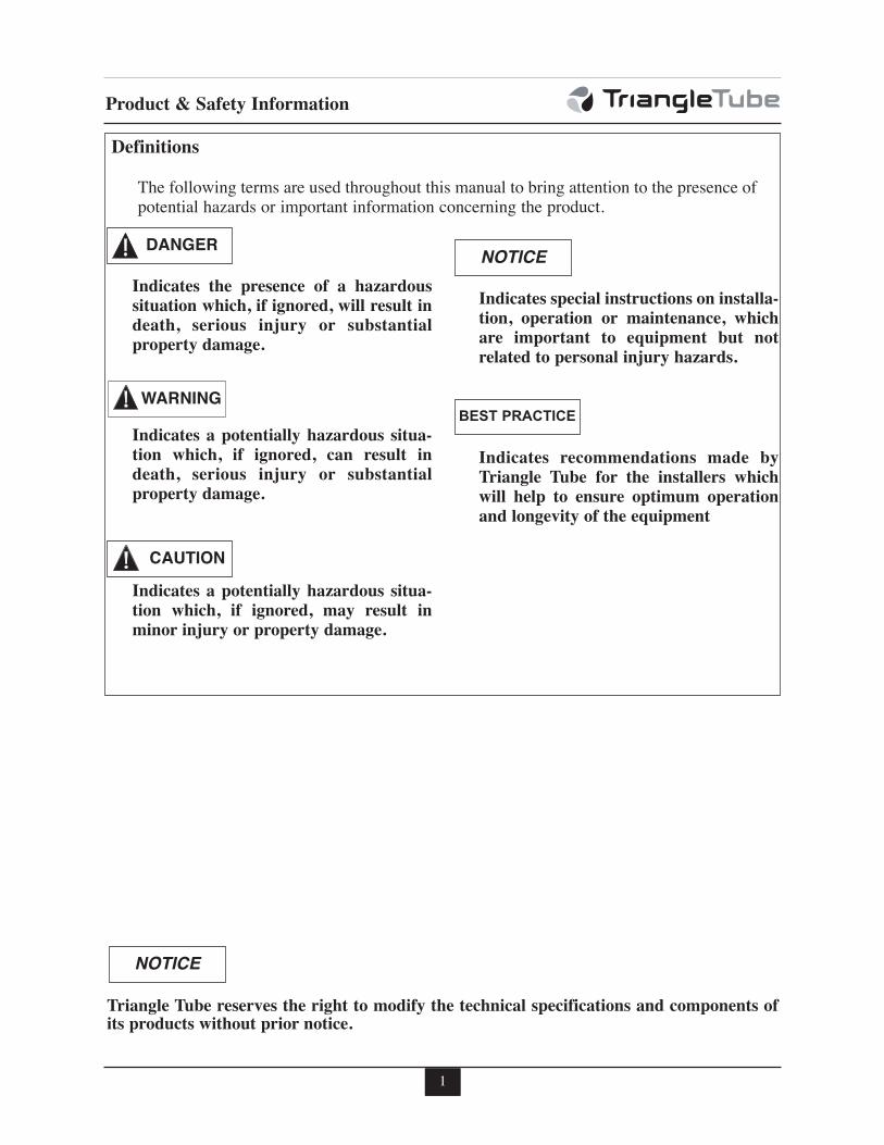
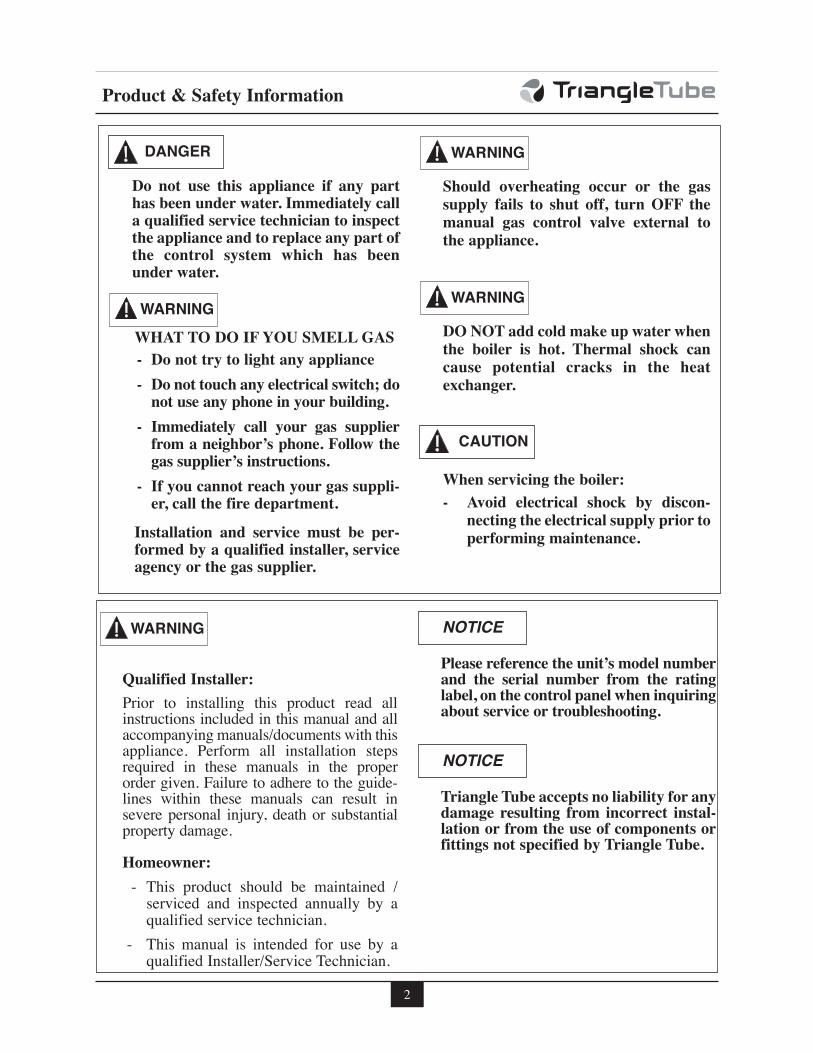
Indicates the presence of a hazardoussituation which, if ignored, will result indeath, serious injury or substantialproperty damage.
Indicates a potentially hazardous situa-tion which, if ignored, can result indeath, serious injury or substantialproperty damage.
Indicates a potentially hazardous situa-tion which, if ignored, may result inminor injury or property damage.
Indicates special instructions on installa-tion, operation or maintenance, whichare important to equipment but notrelated to personal injury hazards.
Indicates recommendations made byTriangle Tube for the installers whichwill help to ensure optimum operationand longevity of the equipment
NOTICE
WARNING
CAUTION
BEST PRACTICE
DANGER
The following terms are used throughout this manual to bring attention to the presence ofpotential hazards or important information concerning the product.
Triangle Tube reserves the right to modify the technical specifications and components ofits products without prior notice.
NOTICE
Definitions
2
Do not use this appliance if any parthas been under water. Immediately calla qualified service technician to inspectthe appliance and to replace any part ofthe control system which has beenunder water.
WHAT TO DO IF YOU SMELL GAS
- Do not try to light any appliance
- Do not touch any electrical switch; donot use any phone in your building.
- Immediately call your gas supplierfrom a neighbor’s phone. Follow thegas supplier’s instructions.
- If you cannot reach your gas suppli-er, call the fire department.
Installation and service must be per-formed by a qualified installer, serviceagency or the gas supplier.
Should overheating occur or the gassupply fails to shut off, turn OFF themanual gas control valve external tothe appliance.
DO NOT add cold make up water whenthe boiler is hot. Thermal shock cancause potential cracks in the heatexchanger.
When servicing the boiler:
- Avoid electrical shock by discon-necting the electrical supply prior toperforming maintenance.
WARNING
WARNING
WARNING
CAUTION
DANGER
Product & Safety Information
Qualified Installer:
Prior to installing this product read allinstructions included in this manual and allaccompanying manuals/documents with thisappliance. Perform all installation stepsrequired in these manuals in the properorder given. Failure to adhere to the guide-lines within these manuals can result insevere personal injury, death or substantialproperty damage.
Homeowner:
- This product should be maintained /serviced and inspected annually by aqualified service technician.
- This manual is intended for use by aqualified Installer/Service Technician.
Please reference the unit’s model numberand the serial number from the ratinglabel, on the control panel when inquiringabout service or troubleshooting.
Triangle Tube accepts no liability for anydamage resulting from incorrect instal-lation or from the use of components orfittings not specified by Triangle Tube.
NOTICE
NOTICE
WARNING
Pre-Installation Items
3
SECTION I - Pre-Installation Items
Code Compliance
This product must be installed in accordance tothe following:
- All applicable local, state, national andprovincial codes, ordinances, regula-tions and laws.
- For installations in Massachusetts, coderequires the boiler to be installed by alicensed plumber or gas fitter, and ifantifreeze is utilized, the installation ofa reduced pressure backflow preventerdevice is required in the boiler’s coldwater fill or make up water supply line.
- For installation in Massachusetts all directvented appliances must comply with theguidelines as outlined on page 11.
- The National Fuel Gas Code NFPA54/ANSI Z 223.1 - Latest edition.
- National Electric Code ANSI/NFPA 70.
- For installations in Canada -“InstallationCode for Gas Burning Equipment”CGA/B149.1 or B149.2 CanadianElectrical Code Part 1 CSA C22.1.
- Standards for Controls and SafetyDevices for Automatically Fired Boilers,ANSI/ASME CSD-1, when required.
The PRESTIGE Solo boiler gas manifoldand gas controls meet the safe lighting andother performance requirements as speci-fied in ANSI Z21.13 latest edition.
Determining Product Location
Before locating the PRESTIGE SOLO checkfor convenient locations to:
- Heating system piping
- Venting
- Gas supply piping
- Electrical service
Ensure the boiler location allows the combus-tion air/vent piping to be routed directly throughthe building and terminate properly outside witha minimum amount of length and bends.
Ensure the area chosen for the installation of thePRESTIGE Solo is free of any combustiblematerials, gasoline and other flammable liquids.
Failure to remove or maintain the areafree of combustible materials, gasolineand other flammable liquids or vaporscan result in severe personal injury,death or substantial property damage.
Ensure the PRESTIGE Solo and its controlsare protected from dripping or spraying waterduring normal operation or service.
The PRESTIGE Solo should be installed in alocation so that any water leaking from theboiler or piping connections or relief valve willnot cause damage to the area surrounding theunit or any lower floors in the structure.
Boiler Replacement
If the PRESTIGE Solo is replacing an existingboiler, the following items should be checkedand corrected prior to installation:
- Boiler piping leaks and corrosion.
- Improper location and sizing of theexpansion tank on the boiler heatingloop.
- If applicable, level and quality of freezeprotection within the boiler system.
Recommended Clearances
The PRESTIGE Solo is approved for zeroclearance to combustibles, excluding vent andboiler piping.
- Boiler Piping - 1/4 inch from com-bustible materials.
NOTICE
WARNING
Pre-Installation Items
- Reference the appropriate vent supple-ment for clearance requirements.
To provide serviceability to the unit it isrecommended that the following clear-ances be maintained:
Top boiler jacket - 24 inches [610 mm].
Front - 24 inches [610 mm].
Bottom boiler piping - 24 inches [610mm].
Rear - 0 inches
Sides - 6 inches [153 mm]
If the clearances listed above cannot bemaintained or the enclosure in which theboiler is installed is less than 85 cubic feet,the space must be ventilated. See page 6for ventilation requirements.
When maintaining zero clearance or lessthan recommended clearances, someproduct labeling may become hiddenand unreadable.
When installing the PRESTIGE Solo ina confined space, sufficient air must beprovided for proper combustion andventing and to allow, under normal oper-ating conditions, proper air flow aroundthe product to maintain ambient tem-peratures within safe limits to complywith the National Fuel Gas Code NFPA54 - latest edition.
Residential Garage Installations
When installing the PRESTIGE Solo in a resi-dential garage, the following special precautionsper NFPA 54/ANSI Z223.1 must be taken:
- Mount the unit a minimum 18 inches[458 mm] above the floor level of thegarage. Ensure the burner and ignitiondevices / controls are no less than 18inches [458 mm] above the floor level.
- Locate or protect the unit in a manner so itcannot be damaged by a moving vehicle.
Boiler Freeze Protection Feature
The TriMax boiler management system has afreeze protection feature built in. This featuremonitors the boiler temperature and responds asfollows when no call for heat is present:
- 46ºF [8ºC] CH (1) & Auxiliary BoilerPumps ON
- 42ºF [6ºC] CH (1), Auxiliary Boiler &System Pumps ON, Burner operates atlow fire
- 60ºF [15ºC] Freeze protection ends.Burner & all pumps OFF after complet-ing CH Post Pump Time.
The boiler freeze protection feature isdisabled during a hard lockout, howeverthe circulators will operate.
The boiler freeze protection feature isdesigned to protect the boiler. The boilershould be installed in a primary/sec-ondary piping arrangement if it isinstalled in an unheated space orexposed to water temperatures of 46ºF orless. See Section IV for primary/sec-ondary piping examples. See Section Xfor antifreeze guides.
NOTICE
WARNING
WARNING
CAUTION
CAUTION
BEST PRACTICE
4
Combustion Air Venting
5
SECTION II - Combustion Air andVenting
Combustion Air Contamination
If the PRESTIGE Solo combustion airinlet is located in any area likely to causeor contain contamination, or if products,which would contaminate the air cannotbe removed, the combustion air must berepiped and terminated to another loca-tion. Contaminated combustion air willdamage the unit and its burner system,resulting in possible severe personalinjury, death or substantial propertydamage.
Do not operate a PRESTIGE Solo if itscombustion air inlet is located near alaundry room or pool facility. Theseareas will always contain hazardous con-taminants.
Pool and laundry products and commonhousehold and hobby products oftencontain fluorine or chlorine compounds.When these chemicals pass through theburner and vent system, they can formstrong acids. These acids can create cor-rosion of the heat exchanger, burnercomponents and vent system, causingserious damage and presenting a possi-ble threat of flue gas spillage or waterleakage into the surrounding area.
Please read the information listed below.If contaminating chemicals are locatednear the area of the combustion air inlet,the installer should pipe the combustionair inlet to an outside area free of thesechemicals per SECTION V of thisinstallation manual.
Potential contaminating products
- Spray cans containing chloro/fluorocar-bons
- Permanent Wave Solutions
- Chlorinated wax
- Chlorine - based swimming pool chem-icals / cleaners
- Calcium Chloride used for thawing ice
- Sodium Chloride used for water soft-ening
- Refrigerant leaks
- Paint or varnish removers
- Hydrochloric acid / muriatic acid
- Cements and glues
- Antistatic fabric softeners used inclothes dryers
- Chlorine-type bleaches, detergents, andcleaning solvents found in householdlaundry rooms
- Adhesives used to fasten building prod-ucts and other similar products
Areas likely to contain these products
- Dry cleaning / laundry areas and estab-lishments
- Beauty salons
- Metal fabrication shops
- Swimming pools and health spas
- Refrigeration Repair shops
- Photo processing plants
- Auto body shops
- Plastic manufacturing plants
- Furniture refinishing areas and estab-lishments
- New building construction
- Remodeling areas
- Garages with workshops
WARNING
WARNING
6
Combustion Air Venting
Ventilation and Combustion AirRequirements - Direct Vent
A Direct Vent appliance utilizes uncontaminedoutdoor air (piped directly to the appliance) forcombustion.
For Direct Vent installations, involving onlythe PRESTIGE Solo, in which the minimumservice clearances are maintained as listed onpage 4, no ventilation openings are required.
For Direct Vent, zero clearance installationsinvolving only the PRESTIGE Solo, the space/ enclosure must provide two openings for ven-tilation. The openings must be sized to provide1 square inch of free area per 1,000 BTUH ofboiler input. The openings shall be placed 12inches from the top of the space and 12 inchesfrom the floor of the space.
For installations in which the PRESTIGE Soloshares the space with air movers (exhaust fan,clothes dryers, fireplaces, etc.) and other com-bustion equipment (gas or oil) the space mustbe provided with adequate air openings to pro-vide ventilation and combustion air to theequipment. To properly size the ventilation /combustion air openings, the installer mustcomply with the National Fuel Gas CodeNFPA 54, ANSI Z223.1 for installations in theU.S or CSA B149.1 and B149.2 for installa-tions in Canada.
The space must be provided with venti-lation / combustion air openings proper-ly sized for all make-up air requirements(exhaust fans, clothes dryers, fireplaces,etc.) and the total input of all applianceslocated in the same space as the PRES-TIGE Solo, excluding the input of aDirect Vent PRESTIGE Solo which usescombustion air directly from the outside,thus additional free area for the open-ings is not required. Failure to provideor properly size the openings couldresult in severe personal injury, death orsubstantial property damage.
Ventilation and Combustion AirRequirements - Category IV
A Category IV appliance utilizes uncontami-nated indoor or outdoor air (surrounding theappliance) for combustion.
In order to reduce the potential risksassociated with indoor contaminates(listed on page 5), flammable vapors andtight housing construction (little or noinfiltration air), it is recommended topipe uncontaminated combustion airdirectly from the outdoors to the appli-ance. This practice also promotes highersystem efficiency by reducing heatedindoor air from being exhausted fromthe house and replaced by cold infiltra-tion air into the house.
For installations in which the PRESTIGE Soloshares the space with air movers (exhaust fan,clothes dryers, fireplaces, etc.) and other com-bustion equipment (gas or oil) the space mustbe provided with adequate air openings to pro-vide ventilation and combustion air to the equip-ment. To properly size the ventilation / com-bustion air openings, the installer must complywith the National Fuel Gas Code NFPA 54,ANSI Z223.1 for installations in the U.S or CSAB149.1 and B149.2 for installations in Canada,as referenced in this section of the manual andtitled Methods of Accessing Combustion Airinto a Space.
The space must be provided with venti-lation / combustion air openings proper-ly sized for all make-up air requirements(exhaust fans, clothes dryers, fireplaces,etc.) and the total input of all appliances,including the PRESTIGE Solo whenlocated in the same space. Failure to pro-vide or properly size the openings couldresult in severe personal injury, death orsubstantial property damage.
WARNING
WARNING
BEST PRACTICE
7
Combustion Air Venting
Methods of Accessing Combustion Air Into ASpace - Category IV
Indoor Combustion Air
The methods listed in this section foraccessing Indoor Combustion Airassume that the infiltration rate is ade-quate and not less than .40 ACH. Forinfiltration rates less than .40 ACH, ref-erence the NFPA 54 National Fuel GasCode for additional guidance.
Opening Size and Location
Openings used to connect indoor spaces shall
be sized and located in accordance with the
following see Fig. 1:
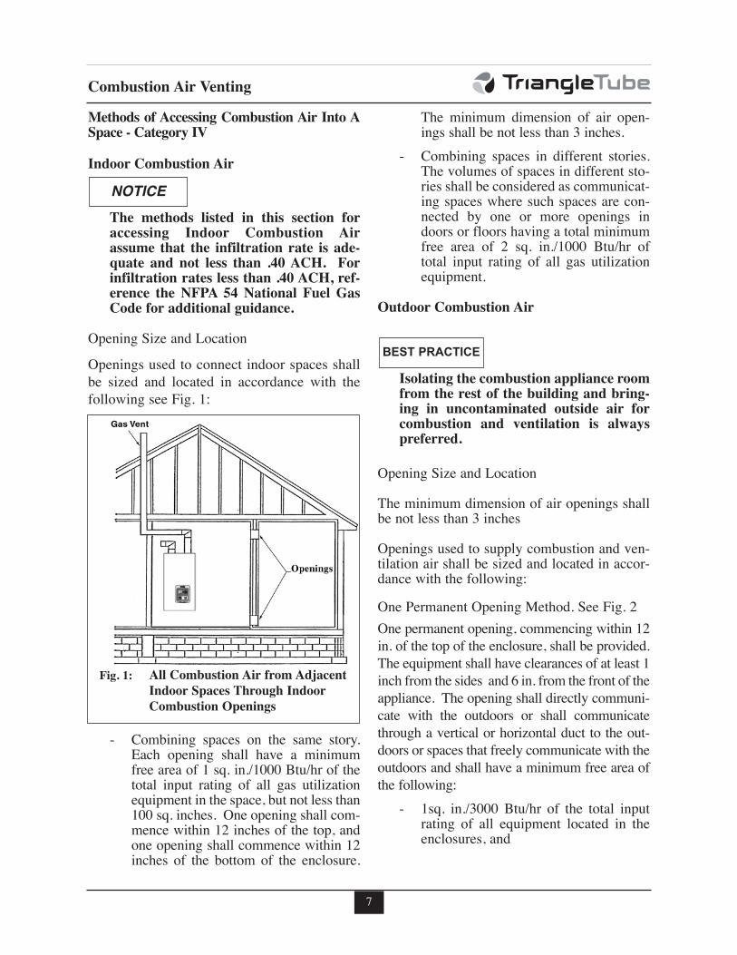
- Combining spaces on the same story.Each opening shall have a minimumfree area of 1 sq. in./1000 Btu/hr of thetotal input rating of all gas utilizationequipment in the space, but not less than100 sq. inches. One opening shall com-mence within 12 inches of the top, andone opening shall commence within 12inches of the bottom of the enclosure.
The minimum dimension of air open-ings shall be not less than 3 inches.
- Combining spaces in different stories.The volumes of spaces in different sto-ries shall be considered as communicat-ing spaces where such spaces are con-nected by one or more openings indoors or floors having a total minimumfree area of 2 sq. in./1000 Btu/hr oftotal input rating of all gas utilizationequipment.
Outdoor Combustion Air
Isolating the combustion appliance roomfrom the rest of the building and bring-ing in uncontaminated outside air forcombustion and ventilation is alwayspreferred.
Opening Size and Location
The minimum dimension of air openings shallbe not less than 3 inches
Openings used to supply combustion and ven-tilation air shall be sized and located in accor-dance with the following:
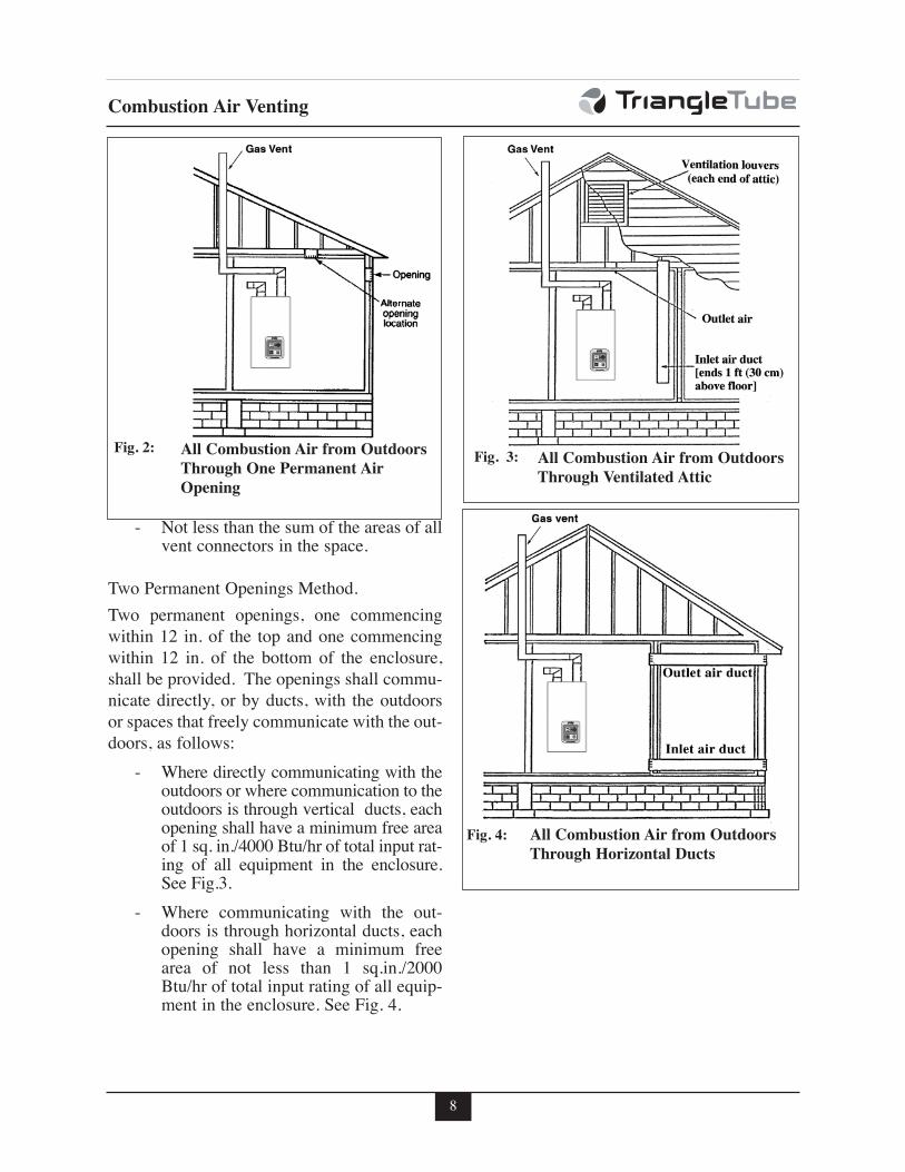
One Permanent Opening Method. See Fig. 2
One permanent opening, commencing within 12
in. of the top of the enclosure, shall be provided.
The equipment shall have clearances of at least 1
inch from the sides and 6 in. from the front of the
appliance. The opening shall directly communi-
cate with the outdoors or shall communicate
through a vertical or horizontal duct to the out-
doors or spaces that freely communicate with the
outdoors and shall have a minimum free area of
the following:
- 1sq. in./3000 Btu/hr of the total inputrating of all equipment located in theenclosures, and
NOTICE
BEST PRACTICE
All Combustion Air from Adjacent
Indoor Spaces Through Indoor
Combustion Openings
Fig. 1:
8
Combustion Air Venting
- Not less than the sum of the areas of allvent connectors in the space.
Two Permanent Openings Method.
Two permanent openings, one commencing
within 12 in. of the top and one commencing
within 12 in. of the bottom of the enclosure,
shall be provided. The openings shall commu-
nicate directly, or by ducts, with the outdoors
or spaces that freely communicate with the out-
doors, as follows:
- Where directly communicating with theoutdoors or where communication to theoutdoors is through vertical ducts, eachopening shall have a minimum free areaof 1 sq. in./4000 Btu/hr of total input rat-ing of all equipment in the enclosure.See Fig.3.
- Where communicating with the out-doors is through horizontal ducts, eachopening shall have a minimum freearea of not less than 1 sq.in./2000Btu/hr of total input rating of all equip-ment in the enclosure. See Fig. 4.
All Combustion Air from Outdoors
Through One Permanent Air
Opening
Fig. 2: All Combustion Air from Outdoors
Through Ventilated Attic
Fig. 3:
All Combustion Air from Outdoors
Through Horizontal Ducts
Fig. 4:
9
Combustion Air Venting
Combination of Indoor and Outdoor
Combustion Air
Indoor Openings: Where used, openings con-
necting the interior spaces shall comply with
the Indoor Combustion Air section on page 7.
Outdoor Opening(s) Location. Outdoor open-
ing(s) shall be located in accordance with the
Outdoor Combustion Air section.
Outdoor Opening(s) Size. Outdoor opening(s) shall
be calculated in accordance with the following:
- The ratio of the interior spaces shall bethe available volume of all communi-cating spaces divided by the requiredvolume.
- The outdoor size reduction factor shallbe 1 minus the ratio of interior spaces.
- The minimum size of outdoor open-ing(s) calculated in accordance with theabove outdoor air section multiplied bythe reduction factor. The minimumdimension of air openings shall not beless than 3 in.
Do not install the PRESTIGE Solo into acommon vent with other gas or oil appli-ances. This may cause flue gas spillage orappliance malfunction, resulting in possi-ble severe personal injury, death or sub-stantial property damage.
Combustion Air and Vent Piping
The PRESTIGE Solo requires a Category IVventing system, which is designed for pressur-ized venting and condensate.
The PRESTIGE Solo is certified per ANSIZ21.13 as a Category IV or Direct Vent (sealedcombustion) appliance. A Category IV appli-ance utilizes uncontamined indoor or outdoorair (surrounding the appliance) for combustion.A Direct Vent appliance utilizes uncontaminat-ed outdoor air (piped directly to the appliance)for combustion.
In order to reduce the potential risksassociated with indoor contaminates(listed on page 5), flammable vaporsand tight housing construction (little orno infiltration air), it is recommendedto pipe uncontaminated combustion airdirectly from the outdoors to the appli-ance. This practice also promotes highersystem efficiency by reducing heatedindoor air from being exhausted fromthe house and replaced by cold infiltra-tion air into the house.
Install combustion air and vent pipe asdetailed in the PRESTIGE Solo VentSupplement included in the boilerinstallation envelope. Refer to optionalvent kit instructions for addition ventinstallation instructions.
Verify installed combustion air and ventpiping are sealed gas tight and meet allprovided instructions and applicablecodes, failure to comply will result insevere personal injury of death.
NOTICE
BEST PRACTICE
DANGER
DANGER
10
Combustion Air Venting
Removal of an Existing Boiler from aCommon Vent System
When an existing boiler is removed from acommon venting system, the common ventingsystem is likely to be too large for properventing of the remaining appliances. At thetime of removal of an existing boiler, the fol-lowing steps shall be followed with eachappliance remaining connected to the com-mon venting system placed in operation,while the other appliances remaining con-nected to the common venting system are notin operation.
1. Seal any unused openings in the commonventing system.
2. Visually inspect the venting system forproper size and horizontal pitch and deter-mine there is no blockage or restriction,leakage, corrosion and other deficiencieswhich could cause an unsafe condition.
3. Insofar as is practical, close all buildingdoors and windows and all doors betweenthe space in which the appliances remain-ing connected to the common venting sys-tem are located and other spaces of thebuilding. Turn on clothes dryers and anyappliance not connected to the commonventing system. Turn on any exhaust fans,such as range hoods and bathroomexhausts, so they will operate at maximumspeed. Do not operate a summer exhaustfan. Close fireplace dampers.
4. Place in operation the appliance beinginspected. Follow the lighting instructions.Adjust thermostat so appliance will operatecontinuously.
5. Test for spillage at the draft hood reliefopening after 5 minutes of main burneroperation. Use the flame of a match or can-dle, or smoke from a cigarette, cigar or pipe.
6. After it has been determined that eachappliance remaining connected to the com-mon venting system properly vents whentested as outlined above, return doors, win-dows, exhaust fans, fireplace dampers, andany other gas-burning appliance to theirprevious condition of use.
7. Any improper operation of the commonventing system should be corrected so theinstallation conforms with the NationalFuel Gas Code, ANSI Z223.1/NFPA 54and/or CAN/CGA B149, Installation codes.When resizing any portion of the commonventing system, the common venting sys-tem should be resized to approach the min-imum size as determined using the appro-priate tables in Part II of the National FuelGas Code ANSI Z223.1/NFPA 54 and/orCAN/CGA B149, Installation codes.
Do not install the PRESTIGE Solo into acommon vent with other gas or oil appli-ances. This may cause flue gas spillage orappliance malfunction, resulting in possi-ble severe personal injury, death or sub-stantial property damage.
BEST PRACTICE
DANGER
11
Combustion Air Venting
For direct-vent appliances, mechanical-vent heating appliances or domestic hotwater equipment, where the bottom of thevent terminal and the air intake is installedbelow four feet above grade the followingrequirements must be satisfied:
1. If there is not one already present, oneach floor level where there are bed-room(s), a carbon monoxide detectorand alarm shall be placed in the livingarea outside the bedroom(s). The car-bon monoxide detector shall complywith NFPA 720 (2005 Edition).
2. A carbon monoxide detector shall alsobe located in the room that houses theappliance or equipment and shall:
a. Be powered by the same electrical cir-cuit as the appliance or equipment suchthat only one service switch servicesboth the appliance and the carbonmonoxide detector;
b. Have battery back-up power;
c. Meet ANSI/UL 2034 Standards andcomply with NFPA 720 (2005 Edition);and
d. Have been approved and listed by theNationally Recognized TestingLaboratory as recognized under 527CMR.
3. A Product-approved vent terminal mustbe used, and if applicable, a Product-approved air intake must be used.Installation shall be in strict compliancewith the manufacturer’s instructions. Acopy of the installation instructionsshall remain with the appliance orequipment at the completion of theinstallation.
4. A metal or plastic identification plateshall be mounted at the exterior of thebuilding, four feet directly above thelocation of vent terminal. The plateshall be of sufficient size to be easilyread from a distance of eight feet away,and read “Gas Vent Directly Below”.
Installer must provide tag identificationplate and ensure the lettering meets coderequirements.
For direct-vent appliances, mechanical-vent heating appliances or domestic hotwater equipment, where the bottom of thevent terminal and the air intake are installedabove four feet above grade the followingrequirements must be satisfied:
1. If there is not one already present, oneach floor level where there are bed-room(s), a carbon monoxide detectorand alarm shall be placed in the livingarea outside the bedroom(s). The car-bon monoxide detector shall complywith NFPA 720 (2005 Edition).
2. A carbon monoxide detector shall:
a. Be located in the room that houses theappliances or equipment;
b. Be either hard wired or battery poweredor both; and
c. Shall comply with NFPA 720 (2005Edition)
3. A Product-approved vent terminal mustbe used, and if applicable, a Product-approved air intake must be used.Installation shall be in strict compliancewith the manufacturer’s instructions. Acopy of the installation instructionsshall remain with the appliance orequipment at the completion of theinstallation.
NOTICE
Commonwealth of Massachusetts Installations Only
12
Unit Preparations
SECTION III - Unit Preparations
Handling Instructions
The PRESTIGE Solo is generally easier tohandle and maneuver once removed from theshipping carton.
To remove the shipping carton:
Use care not to drop, bump or rotate theboiler upside down, as damage to theboiler will result.
1. Remove any shipping straps and open theside of the shipping carton.
2. Slide the unit with the foam inserts out ofthe carton.
3. Discard all packing materials.
Wall Mounting Installation
The PRESTIGE Solo should be wall mountedusing the bracket provided with the boiler. ThePRESTIGE Solo is not designed for floorinstallation. If floor installation is required anoptional floor stand is available throughTriangle Tube.
The wall used for mounting the PRES-TIGE Solo must be vertically plumbedand capable of supporting a minimum130 pounds [59 kg] for the PRESTIGESolo 60, 175 pounds [80 kg] for PRES-TIGE Solo 175/250 and 250 pounds [115Kg] for PRESTIGE Solo 399. Failure tocomply with these requirements couldresult in personal injury, death or sub-stantial property damage.
Wall Mounting Guidelines
1. The wall-mounting bracket is designed forstud spacing of 12 inch or 16 inch on cen-ters. For unconventional stud spacing, asolid / secure mounting surface must beprovided for installation of the bracket.
2. For applications using wood studs, installthe bracket using the lag screws providedwith the boiler. Ensure both lag screws areinstalled securely in the studs.
3. For applications using metal studs, installthe bracket to the studs using 3/16” togglebolts and washers.
4. DO NOT mount or attempt to mount thewall bracket to hollow sheet rock or lathwalls using anchors. Only install boiler tostuds or equivalent wood structure.
5. For applications using solid walls (rock,concrete, brick, cinder block, etc.), installthe wall bracket using anchors (doubleexpansion shields) and bolts with washersprovided with the boiler.
6. The boiler is too heavy and bulky for a sin-gle person to lift and attempt to mount; aminimum of 2 people is required formounting the boiler.
Use extreme care not to drop the boileror cause bodily injury while lifting ormounting the boiler onto the bracket.Once mounted verify that the boiler issecurely attached to the bracket andwall. Failure to comply with the aboveguidelines could result in property dam-age, personal injury or death.
NOTICE
NOTICE
CAUTION
13
Unit Preparations
PRESTIGE Solo 60/175/250 Stud Walls -Installation
1. Locate the studs in the general area of theboiler placement.
2. Place the wall-mounting bracket on thewall centering the mounting slots with thestud centers and ensuring the upper edge ofthe bracket is away from the wall.
3. Level the bracket, while maintaining it’scentering with the studs and use a pencil tomark the location of the mounting slots.
4. Remove the bracket from the wall and drill1/4” diameter hole by 3” deep positioned inthe center of each mark. For applicationsusing metal studs and 3/16” toggle bolts,drill the required clearance hole.
5. Reposition the bracket onto the wall andalign mounting slots/holes. Insert the twolag screws provided (or toggle bolts formetal studs) through the mountingslots/holes and loosely tighten.
6. Level bracket and tighten screws (bolts formetal studs) securely making sure not toover-tighten to avoid damaging drywall orplaster.
PRESTIGE Solo 399 Stud Walls -Installation
1. To distribute the weight of the boiler even-ly when mounting onto a stud wall it is rec-ommended to use the PRESTIGE SoloWall Frame kit.
2. When using the wall frame to mount theboiler reference the kit installation instruc-tions and ensure the frame is securely fas-tened to the wall.
3. If the structure of wall is questionable, insupporting a minimum weight of 250pounds [115 kg.], it is recommended to usethe optional floor stand.
Wall Bracket Installation - Solid Walls
1. Locate the general area of the boiler place-ment.
2. Place the wall-mounting bracket on thewall ensuring the upper edge of the bracketis away from the wall.
3. Level the bracket and use a pencil to markthe location of the mounting slots on thewall.
4. Remove the bracket from the wall and drilla 5/8” diameter hole by 1-3/8” deep posi-tioned in the center of each mark.
5. Install the anchors (provided) flush orslightly recessed in the drilled holes withthreaded side facing down.
6. Reposition the bracket on the wall andalign mounting slots/holes. Insert the twobolts (provided) through the mountingslots/holes and loosely tighten.
7. Level bracket and tighten bolts securely.
Boiler Mounting
1. Obtain assistance in lifting the boiler ontothe wall bracket.
2. Install the boiler making sure the boilermounting lip located along the upper edgeof the rear jacket panel engages the wall-mounting bracket. Ensure the boiler isseated properly and is secure.
Boiler Piping
SECTION IV - Boiler Piping
General Piping Requirements
- All plumbing must meet or exceed all local,state and national plumbing codes.
- Support all piping using hangers. DO NOTsupport piping by the unit or its components.
- Use isolation valves to isolate system com-ponents.
- Install unions for easy removal of thePRESTIGE Solo from the system piping.
Use a two wrench method when tighten-ing piping onto the boiler connections.Use one wrench to prevent the boilerpiping from turning / twisting. Failureto support the boiler piping and connec-tions in this manner could cause damageto the boiler and its components.
Pressure Relief Valve
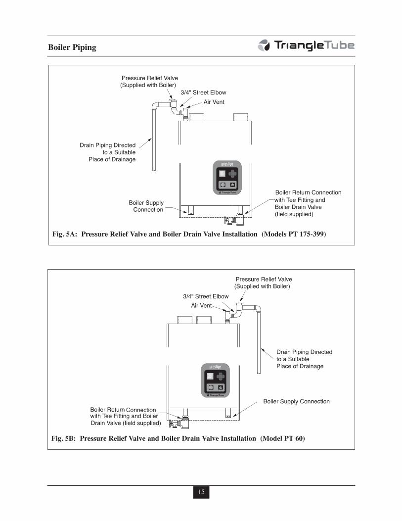
1. The PRESTIGE Solo is supplied with a 30psi pressure relief valve and must be pipedusing the PRV connection as shown in Fig.5 page 15.
2. To avoid potential water damage to the sur-rounding area or potential scalding hazarddue to the operation of the relief valve, thedischarge piping:
- Must be connected to the discharge out-let of the relief valve and directed to asafe place of disposal.
- Length should be as short and direct aspossible. The size of the discharge lineshould not be reduced, maintain thesame size as the outlet of the relief valve.
- Should be directed downward towardsthe floor at all times. The piping shouldterminate at least 6 inches [153 mm]above any drain connection to allowclear visibility of the discharge.
- Should terminate with a plain end, notwith a threaded end. The material ofthe piping should have a serviceabletemperature rating of 250ºF or greater.
- Should not be subject to conditionswhere freezing could occur.
- Should not contain any shut-off valvesor obstructions. No shut-off valveshould be piped between the boiler andrelief valve.
Failure to comply with the guidelines oninstalling the pressure relief valve anddischarge piping can result in personalinjury, death or substantial propertydamage.
Low Water Cutoff Device
- The PRESTIGE Solo is equipped with a fac-tory installed pressure switch type Low WaterCut Off device.
- The minimum operating system pressureallowable with this device is 10 psig.
- Check local codes if a Low Water CutoffDevice is required. If so, determine if thisdevice meets the requirements of the localcodes.
The PRESTIGE Solo control system alsosenses the system water temperaturesentering and exiting the heat exchangerto provide protection against low waterconditions Where local codes and juris-diction do not accept a pressure devicefor low water protection, the jurisdic-tions may accept these PRESTIGE Solointegral control functions as a means ofproviding low water protection.
NOTICE
WARNING
WARNING
14
15
Boiler Piping
Boiler Return Connection with Tee Fitting and Boiler Drain Valve(field supplied)
Boiler Supply Connection
Pressure Relief Valve(Supplied with Boiler)
3/4" Street ElbowAir Vent
Drain Piping Directedto a Suitable
Place of Drainage
Fig. 5A: Pressure Relief Valve and Boiler Drain Valve Installation (Models PT 175-399)
Boiler Supply Connection
with Tee Fitting and BoilerDrain Valve (field supplied)
Boiler Return Connection
Pressure Relief Valve(Supplied with Boiler)
Drain Piping Directedto a SuitablePlace of Drainage
3/4" Street ElbowAir Vent
Fig. 5B: Pressure Relief Valve and Boiler Drain Valve Installation (Model PT 60)
Boiler Piping
Additional Limit Control
If a separate LWCO device is required by cer-tain local jurisdictions or when the boiler isinstalled above the system piping, the follow-ing guidelines must be followed:
- The LWCO device must be designedfor water installations, electrode probe-type is recommended.
- The LWCO device must be installed ina tee connection on the boiler supplypiping above the boiler.
- Wiring of the LWCO device to the PRES-TIGE Solo is done directly onto the lowvoltage terminal strip, reference Fig. 19page 31 for available terminals for anexternal limit (manual or auto reset).
If the installation is to comply with ASME orCanadian requirements, an additional hightemperature limit may be needed. Consultlocal code requirements to determine compli-ance. The limit should be installed as follows:
- Install the limit in the boiler supply pip-ing between the boiler and any isolationvalve.
- Maximum set point for the limit is194ºF.
- For wiring of the limit reference Fig. 19,page 31, using the external limit/manualreset terminals on the low voltage termi-nal strip. This will provide a "hard"lockout requiring a manual reset of thecontrol.
Backflow Preventer
- Use a backflow preventer valve in themake-up water supply to the unit asrequired by local codes.
Boiler System Piping Applications
It is recommended on all piping applica-tions to utilize a primary/secondary pipingarrangement as a means to provide freezeprotection of the boiler, which is an integralfunction of the boiler control. Maintain theminimum boiler flow rate, see Graphs 2through 7 on pages 91 through 93. Forother piping arrangements, consult theEngineering Department at Triangle Tubeor consult other approved/recognizeddesign arrangements.
On piping applications utilizing a singlezone or other recognized piping designarrangements, it is recommended that theinstaller uses flow/check valves withweighted seats at or near the appliance toprevent gravity circulation.
Expansion Tank and Makeup Water
Ensure the expansion tank is properly sized forthe boiler volume (3 gallons [12 L] for thePRESTIGE Solo 60, 5 gallons [19 L] for thePRESTIGE Solo 175/250, 7 gallons [26 L] forPRESTIGE Solo 399) and the system volumeand temperature.
Undersized expansion tanks will causesystem water to be lost through the pres-sure relief valve and cause additionalmakeup water to be added to the system.Eventual boiler heat exchanger failurecan result due to this excessive makeupwater addition.
The expansion tank must be located as shownin Fig. 7 and Fig. 8 on page 19 when using aprimary/secondary piping arrangement or asper recognized design methods. Refer to theexpansion tank manufacturer instructions foradditional installation details.
CAUTION
BEST PRACTICE
BEST PRACTICE
16
Boiler Piping
Connect the expansion tank to an air separatoronly if the air separator is located on the suc-tion side (inlet) of the system circulator.Always locate and install the system fill con-nection at the same location as the expansiontank connection to the system.
Diaphragm Expansion Tank
Always install an automatic air vent on the topof the air separator to remove residual air fromthe system.
Closed-Type Expansion Tank
It is recommended to pitch any horizontal pipingupwards toward the expansion tank 1 inch per 5feet of piping. Use 3/4” piping for the expansiontank to allow air within the system to rise.
DO NOT install automatic air vents on aclosed-type expansion tank system. Airmust remain in the system and bereturned to the expansion tank to pro-vide an air cushion. An automatic airvent would cause air to be vented fromthe system resulting in a water-loggedexpansion tank.
Circulator
The PRESTIGE Solo requires an external circula-tor to provide circulation through the boiler. Thecirculator when wired directly to the PRESTIGESolo will allow for domestic hot water priority andto provide circulation for the freeze protection fea-ture of the boiler control. See Graphs 2 through 7on pages 91 & 93 for pressure drop and minimumflow rate through the boiler.
Sizing Primary Piping
See Fig. 9 through 13, pages 21 - 23, for rec-ommended piping arrangements based on vari-ous applications. Size the piping and systemcomponents required in the space heating sys-tem, using recognized design methods.
Domestic Hot Water System Piping
See Fig. 9 through 12, page 21-22 for recom-mended piping to a DHW system. This recom-mended piping configuration ensures priority isgiven to the production and recovery of the DHW.
The piping for the DHW is separate from theboiler system piping and does not require a pri-mary / secondary piping configuration.
To wire the DHW circulator to the boiler controlmodule, reference Section VIII - External Wiring.
System Piping - Zone Circulators
Connect the PRESTIGE Solo to the systempiping as shown in Fig. 9 page 21 when zoningwith zone circulators.
The installer must provide a separate circulatorfor each zone of space heating as well as theboiler circulator.
To ensure an adequate flow rate throughthe PRESTIGE Solo, the boiler supply andreturn piping size must be a minimum of 1inch for the PRESTIGE Solo 60, 1-1/4 inchfor the PRESTIGE Solo 175/250 and 1-1/2inch for the PRESTIGE Solo 399.
System Piping - Zone Valves
Connect the PRESTIGE Solo to the system pip-ing as shown in Fig. 10 page 21 when zoningwith zone valves. The primary / secondary pipingensures that the boiler loop has sufficient flow.
To ensure an adequate flow rate throughthe PRESTIGE Solo, the boiler supplyand return piping size must be a mini-mum of 1 inch for the PRESTIGE Solo 60,1-1/4 inch for the PRESTIGE Solo175/250 and 1-1/2 inch for the PRESTIGESolo 399.
NOTICE
CAUTION
NOTICE
17
18
Boiler Piping
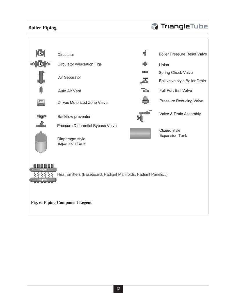
Fig. 6: Piping Component Legend
19
Boiler Piping
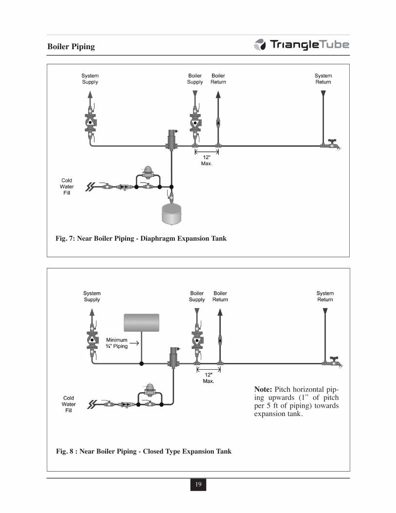
Fig. 8 : Near Boiler Piping - Closed Type Expansion Tank
Fig. 7: Near Boiler Piping - Diaphragm Expansion Tank
Note: Pitch horizontal pip-ing upwards (1” of pitchper 5 ft of piping) towardsexpansion tank.
20
Boiler Piping
System Piping - Through Boiler
In new or retrofit applications in whichprimary/secondary arrangement is not utilized, thePRESTIGE Solo allows this flexibility due to alower boiler pressure drop, see Graphs 2 through7 on pages 91 through 93.
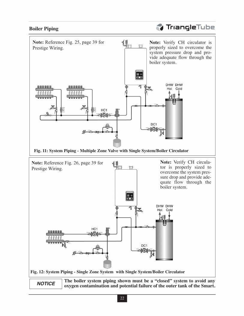
Figure 11, page 22 illustrates a multiple zonevalve system with a single system/boiler circu-lator. A by-pass loop with a pressure differentialvalve must be installed on the system piping.
Figure 12, page 22 illustrates a single zone utiliz-ing the boiler circulator as the system circulator.
System Piping - Radiant Heating
The heat exchanger design of the PRESTIGEallows operation in a condensing mode. Thisfeature requires no regulation of the returntemperature back to the boiler in radiant heat-ing applications.
The design and construction of the PRESTIGEheat exchanger allows the installation of the boil-er on systems with non - oxygen barrier tubing.
DO NOT install a SMART tank alongwith the PRESTIGE in systems withnon-oxygen barrier tubing. Failure tocomply could result in premature failureof the SMART tank.
The boiler water supply temperature can bemaintained by the PRESTIGE, eliminatingthe need for a mix system to achieve thedesired temperature.
It is recommended for the installer to install ahigh temperature limit to ensure that the pri-mary supply temperature does not exceed themaximum allowable temperature for the radi-ant tubing.
Size the system piping and circulator to pro-vide the flow needed for the radiant system.
To ensure an adequate flow rate throughthe PRESTIGE Solo, the boiler supplyand return piping size must be a mini-mum of 1 inch for the PRESTIGE Solo 60,1-1/4 inch for the PRESTIGE Solo175/250 and 1-1/2 inch for the PRESTIGESolo 399.
The addition of the high temperature limitis important if the PRESTIGE is connect-ed to a domestic hot water system, whichrequires a high primary supply watertemperature.
System Piping - Special Application
If the boiler is used in conjunction with achilled water/medium system, the boiler andchiller must be piped in parallel. Installflow/check valves to prevent the chilled medi-um from entering into the boiler.
If the boiler is used to supply hot water to theheating coils of an air handler where they maybe exposed to chilled air circulation, installflow/check valves or other automatic meansto prevent gravity circulation of the boilerwater during cooling cycles.
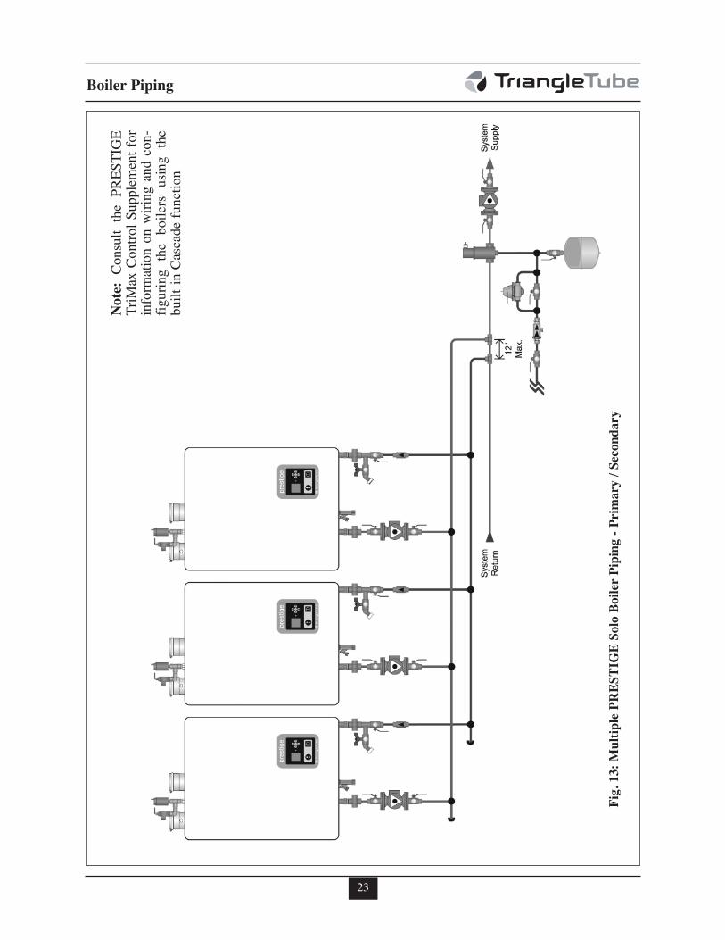
System Piping - Multiple Units Installation
Use a balanced manifold system as the prima-ry / secondary connection to the space heatingpiping as shown in Fig. 13 page 23.
Maintain a minimum of 6 inches [153 mm] ofclearance between units to allow for servicing.
For the space heating piping refer to the appli-cations mentioned in this manual or use recog-nized design methods.
CAUTION
NOTICE
NOTICE
21
Boiler Piping
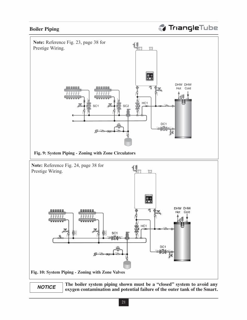
Fig. 9: System Piping - Zoning with Zone Circulators
Fig. 10: System Piping - Zoning with Zone Valves
The boiler system piping shown must be a “closed” system to avoid anyoxygen contamination and potential failure of the outer tank of the Smart.NOTICE
Note: Reference Fig. 23, page 38 for
Prestige Wiring.
Note: Reference Fig. 24, page 38 for
Prestige Wiring.
22
Boiler Piping
Fig. 11: System Piping - Multiple Zone Valve with Single System/Boiler Circulator
Fig. 12: System Piping - Single Zone System with Single System/Boiler Circulator
Note: Verify CH circulator isproperly sized to overcome thesystem pressure drop and pro-vide adequate flow through theboiler system.
Note: Verify CH circula-tor is properly sized toovercome the system pres-sure drop and provide ade-quate flow through theboiler system.
The boiler system piping shown must be a “closed” system to avoid anyoxygen contamination and potential failure of the outer tank of the Smart.NOTICE
Note: Reference Fig. 25, page 39 for
Prestige Wiring.
Note: Reference Fig. 26, page 39 for
Prestige Wiring.
23
Boiler Piping
Fig
. 13:
Mu
ltip
le P
RE
ST
IGE
Solo
Boil
er P
ipin
g -
Pri
mary
/ S
econ
dary
Note
:C
onsu
lt
the
PR
ES
TIG
ET
riM
ax C
ontr
ol
Supple
men
t fo
rin
form
atio
n o
n w
irin
g a
nd c
on
-fi
guri
ng
the
boil
ers
usi
ng
the
buil
t-in
Cas
cade
funct
ion
24
Installing Vent/Combustion Air & Condensate Drain
SECTION V - Installing Vent /Combustion Air & Condensate Drain
Installing Vent and Combustion Air
The PRESTIGE Solo must be vented andsupplied with combustion air as shown inthe PRESTIGE Solo Vent Supplement,included in the boiler installation enve-lope. Refer to optional vent kit instruc-tions for additional vent installationinstructions. Once installation is complet-ed, inspect the vent and combustion airsystem thoroughly to ensure systems areairtight and comply with the instructionsgiven in the venting supplement and arewithin all requirements of applicablecodes. Failure to comply with the installa-tion requirements on the venting andcombustion air piping will cause severepersonal injury or death.
Installing Condensate Drain Assembly
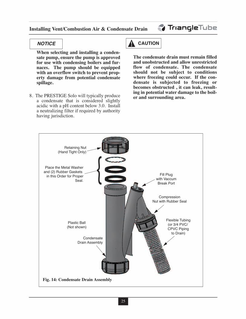
1. Locate the condensate drain assembly andinstall as shown in Fig. 14 page 25.
The installer may want to fill the con-densate trap with water prior to assem-bling on the unit.
2. Remove the retaining nut, metal washer andrubber seals from the condensate drain assem-bly and slide over the heat exchanger conden-sate drain nipple. Make sure to place the metalwasher on top of the rubber seals. Connect thecondensate drain assembly to the retaining nutand tighten. Hand tight only!
Ensure installation of the condensatedrain assembly included the metal wash-er. Failure to comply could result in thetrap assembly dislocating from the boiler.
Ensure the condensate drain assemblycontains the plastic seated ball. Do notinstall the condensate drain assembly ifthe ball is lost or missing, replace theentire assembly.
3. Remove the compression nut and rubberseal from the drain outlet.
4. Using 3/4” x 2’ flexible PVC tube provid-ed, slide the compression nut and rubberseal over the pipe
The use of 3/4” PVC or CPVC pipe isalso acceptable. If 3/4” pipe is useddeburr and chamfer pipe to allow mat-ing onto the drain assembly.
5. Thread the rubber seal into the compres-sion nut to ease installation of the pipe tothe drain assembly.
6. Seat the pipe onto the drain assembly andtighten the compression nut. Hand tightonly!
The installer may opt to using 13/16" IDtubing in lieu of rigid piping.
The drain line materials must be anapproved material by the authority hav-ing jurisdiction. In absence of suchauthority, PVC and CPVC piping mustcomply with ASTM D1785 or D2845.The cement and primer used on the pip-ing must comply with ASME D2564 orF493. For installations in Canada, useCSA or ULC certified PVC or CPVCpipe, fittings and cement/primer.
7. Continue the pipe from the drain assemblyto a floor drain or condensate pump.
NOTICE
WARNING
NOTICE
DANGER
NOTICE
NOTICE
WARNING
25
Installing Vent/Combustion Air & Condensate Drain
When selecting and installing a conden-sate pump, ensure the pump is approvedfor use with condensing boilers and fur-naces. The pump should be equippedwith an overflow switch to prevent prop-erty damage from potential condensatespillage.
8. The PRESTIGE Solo will typically producea condensate that is considered slightlyacidic with a pH content below 3.0. Installa neutralizing filter if required by authorityhaving jurisdiction.
The condensate drain must remain filledand unobstructed and allow unrestrictedflow of condensate. The condensateshould not be subject to conditionswhere freezing could occur. If the con-densate is subjected to freezing orbecomes obstructed , it can leak, result-ing in potential water damage to the boil-er and surrounding area.
NOTICE CAUTION
Flexible Tubing(or 3/4 PVC/ CPVC Piping
to Drain)
CompressionNut with Rubber Seal
Fill Plugwith VaccumBreak Port
CondensateDrain Assembly
Plastic Ball(Not shown)
Retaining Nut(Hand Tight Only)
Place the Metal Washerand (2) Rubber Gaskets
in this Order for ProperSeal.
Fig. 14: Condensate Drain Assembly
26
Gas Piping
SECTION VI - Gas Piping
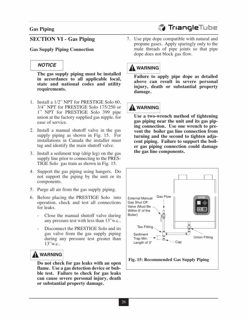
Gas Supply Piping Connection
The gas supply piping must be installedin accordance to all applicable local,state and national codes and utilityrequirements.
1. Install a 1/2” NPT for PRESTIGE Solo 60,3/4” NPT for PRESTIGE Solo 175/250 or1” NPT for PRESTIGE Solo 399 pipeunion at the factory supplied gas nipple, forease of service.
2. Install a manual shutoff valve in the gassupply piping as shown in Fig. 15. Forinstallations in Canada the installer musttag and identify the main shutoff valve.
3. Install a sediment trap (drip leg) on the gassupply line prior to connecting to the PRES-TIGE Solo gas train as shown in Fig. 15.
4. Support the gas piping using hangers. Donot support the piping by the unit or itscomponents.
5. Purge all air from the gas supply piping.
6. Before placing the PRESTIGE Solo intooperation, check and test all connectionsfor leaks.
- Close the manual shutoff valve duringany pressure test with less than 13”w.c..
- Disconnect the PRESTIGE Solo and itsgas valve from the gas supply pipingduring any pressure test greater than13”w.c..
Do not check for gas leaks with an openflame. Use a gas detection device or bub-ble test. Failure to check for gas leakscan cause severe personal injury, deathor substantial property damage.
7. Use pipe dope compatible with natural andpropane gases. Apply sparingly only to themale threads of pipe joints so that pipedope does not block gas flow.
Failure to apply pipe dope as detailedabove can result in severe personalinjury, death or substantial propertydamage.
Use a two-wrench method of tighteninggas piping near the unit and its gas pip-ing connection. Use one wrench to pre-vent the boiler gas line connection fromturning and the second to tighten adja-cent piping. Failure to support the boil-er gas piping connection could damagethe gas line components.
NOTICE
WARNING
WARNING
WARNING
Sediment
Trap Min.
Length of 3"
Union Fitting
Cap
Tee Fitting
External Manual
Gas Shut Off
Valve (Must Be
Within 6' of the
Boiler)
Gas Flow
Fig. 15: Recommended Gas Supply Piping
27
Gas Piping
NATURAL GAS
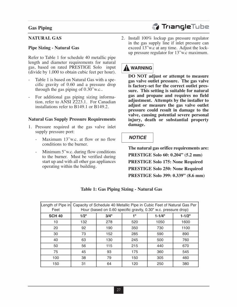
Pipe Sizing - Natural Gas
Refer to Table 1 for schedule 40 metallic pipelength and diameter requirements for naturalgas, based on rated PRESTIGE Solo input(divide by 1,000 to obtain cubic feet per hour).
- Table 1 is based on Natural Gas with a spe-cific gravity of 0.60 and a pressure dropthrough the gas piping of 0.30”w.c..
- For additional gas piping sizing informa-tion, refer to ANSI Z223.1. For Canadianinstallations refer to B149.1 or B149.2.
Natural Gas Supply Pressure Requirements
1. Pressure required at the gas valve inletsupply pressure port:
- Maximum 13”w.c. at flow or no flowconditions to the burner.
- Minimum 5”w.c. during flow conditionsto the burner. Must be verified duringstart up and with all other gas appliancesoperating within the building.
2. Install 100% lockup gas pressure regulatorin the gas supply line if inlet pressure canexceed 13”w.c at any time. Adjust the lock-up pressure regulator for 13”w.c maximum.
DO NOT adjust or attempt to measuregas valve outlet pressure. The gas valveis factory-set for the correct outlet pres-sure. This setting is suitable for naturalgas and propane and requires no fieldadjustment. Attempts by the installer toadjust or measure the gas valve outletpressure could result in damage to thevalve, causing potential severe personalinjury, death or substantial propertydamage.
The natural gas orifice requirements are:
PRESTIGE Solo 60: 0.204” (5.2 mm)
PRESTIGE Solo 175: None Required
PRESTIGE Solo 250: None Required
PRESTIGE Solo 399: 0.339” (8.6 mm)
WARNING
NOTICE
Table 1: Gas Piping Sizing - Natural Gas
Length of Pipe in
Feet
Capacity of Schedule 40 Metallic Pipe in Cubic Feet of Natural Gas Per
Hour (based on 0.60 specific gravity, 0.30" w.c. pressure drop)
SCH 40 1/2" 3/4" 1" 1-1/4" 1-1/2"
10 132 278 520 1050 1600
20 92 190 350 730 1100
30 73 152 285 590 890
40 63 130 245 500 760
50 56 115 215 440 670
75 45 93 175 360 545
100 38 79 150 305 460
150 31 64 120 250 380
28
Gas Piping
PROPANE GAS
Pipe Sizing - Propane Gas
Contact the local propane gas supplier for rec-ommended sizing of piping, tanks and 100%lockup gas regulator.
Propane Gas Supply Pressure Requirements
1. Adjust the propane supply regulator pro-vided by the gas supplier for 13”w.c. max-imum pressure
2. Pressure required at the gas valve inlet sup-ply pressure port:
- Maximum 13”w.c. at flow or no flowconditions to the burner
- Minimum 5”w.c. during flow conditionsto the burner. Must be verified duringstart up and with all other gas appliancesoperating within the building.
DO NOT adjust or attempt to measuregas valve outlet pressure. The gas valveis factory-set for the correct outlet pres-sure. This setting is suitable for naturalgas and propane and requires no fieldadjustment. Attempts by the installer toadjust or measure the gas valve outletpressure could result in damage to thevalve, causing potential severe personalinjury, death or substantial propertydamage.
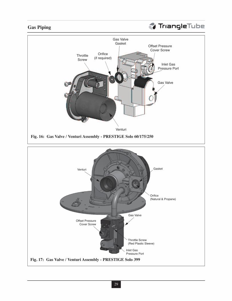
Prior to start up, ensure the unit is set tofire propane. Check the rating label forthe type of fuel. Check the gas valve forpropane conversion label. If there is aconflict or doubt on the burner set up,remove the gas valve and check for thepropane orifice, see Fig. 16 or 17, page29. Failure to ensure proper burnersetup could result in severe personalinjury, death or substantial propertydamage.
The propane orifice requirements are:
PRESTIGE Solo 60: 0.120” (3.1 mm)
PRESTIGE Solo 175: 0.221” (5.6 mm)
PRESTIGE Solo 250: 0.250” (6.3 mm)
PRESTIGE Solo 399: 0.264” (6.7 mm)
WARNING
WARNING
NOTICE
29
Gas Piping
Gas Valve
Inlet GasPressure Port
Offset PressureCover Screw
GasketVenturi
Orifice(Natural & Propane)
Throttle Screw(Red Plastic Sleeve)
Fig. 17: Gas Valve / Venturi Assembly - PRESTIGE Solo 399
Venturi
Orifice
(if required)Throttle
Screw
Gas Valve
Gasket
Gas Valve
Offset Pressure
Cover Screw
Inlet Gas
Pressure Port
Fig. 16: Gas Valve / Venturi Assembly - PRESTIGE Solo 60/175/250
30
Internal Wiring
SECTION VII - Internal Wiring
ELECTRICAL SHOCK HAZARD. Foryour safety, disconnect electrical powersupply to the unit before servicing ormaking any electrical connections toavoid possible electric shock hazard.Failure to do so can cause severe person-al injury or death.
Prior to servicing, label all wires beforedisconnecting. Wiring errors can causeimproper and dangerous operation.Verify proper wiring and operation afterservicing.
General Requirements
- Wiring must be N.E.C Class 1.
- If original wiring as supplied with the unitmust be replaced, use only Type T 194ºF[90ºC] wire or equivalent as a minimum.
- The PRESTIGE must be electricallygrounded as required by NationalElectrical Code ANSI/NFPA 70 - latest edi-tion and / or the Canadian Electrical CodePart 1, CSA C22.1, Electrical Code.
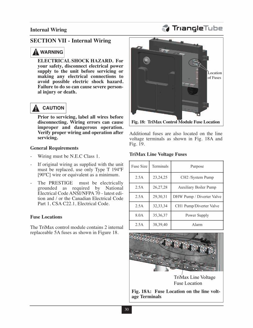
Fuse Locations
The TriMax control module contains 2 internalreplaceable 5A fuses as shown in Figure 18.
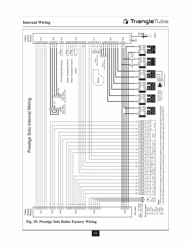
Additional fuses are also located on the linevoltage terminals as shown in Fig. 18A andFig. 19.
TriMax Line Voltage Fuses
CAUTION
WARNING
Locationof Fuses
Fig. 18: TriMax Control Module Fuse Location
TriMax Line VoltageFuse Location
Fig. 18A: Fuse Location on the line volt-age Terminals
Fuse Size Terminals Purpose
2.5A 23,24,25 CH2 /System Pump
2.5A 26,27,28 Auxiliary Boiler Pump
2.5A 29,30,31 DHW Pump / Diverter Valve
2.5A 32,33,34 CH1 Pump/Diverter Valve
8.0A 35,36,37 Power Supply
2.5A 38,39,40 Alarm
31
Internal Wiring
12
CH1
Thermostat
34
CH2
Thermostat
56
Outdoor
Sensor
78
DHW
Aquasta
torSensor
910
Manual
Reset
Limit
1112
Auto
Reset
Limit
1314
+-
Modula
tion
Signal
1516
Syste
mSensor
1718
19
Cascade
Master
2021
22A
BG
Modbus
25L
GN
CH2Pump/
Syste
mPump
2324
37L
GN
Powe
rSupply
3536
40
Alarm
3839
CascadeSlave
31*
LG
NDH
WPump/
*Dive
rterV
alve
29*3
0 Circula
torTermina
ls
28L
GN
Auxiliary
BoilerP
ump
2627 Circula
torfactory
wiredon
Prestige
Solo110only.
1471142812513651654321
G NL
X00
X01
X11
X13
X14
X02
X15
TriMax
Control
Module
On/O
ffSw
itch
6543213291054168763 14187329
X03
X04
X07
X05
X01
TriMax
Display
Module
5 43X06
2
948372105712683 2 13 2
5 6 3 4
Flue
TemperatureSensor
SupplyTemperatureSensor
ReturnTemperatureSensor
LWCO
BKBKBKBK
BKBK
BKBK
WW
VV
BRBR
OO
BLBL
RR
WW
WBR
YGY
BKBK
BKBK
BKR
WW
WW
WR
W W W W W WWW
V V BR BR O O
BLBLRRWWWBRYGYY Y Y Y Y Y RRBKBK
BK R BL W BK W BK W BK W BK W BK WOBLBLRRYYWBKWBKYYYYYY O
1 2 4 53 2 1
Blow
erPowe
rTermina
ls
Blow
erBlow
erSignalTermina
ls
GND
5
GasV
alve
(Alle
xceptSolo
399)
V1 V1 G V2 V2
GND
GasV
alve
(Solo
399only)
1 3GN
D
F00
GND
GND
Ignitor
Notes:
1.Ifanyo
fthe
originalwire
suppliedwiththeappliance
mustberepla
ced,itm
ustberepla
cedwiththesametyp
eorits
equiv
alent.
2.All120
VACfieldwiringtotheboilershallh
aveaminimum
sizeof14
AWGwithatemperatureratingofat
least194°F[90°C].
Wire
Legend
-Low
Voltage
-Line
Voltage
-Ignitio
nCa
ble
Wire
ColorLegend
BK–Black
W–White
GR–Green
BL–Blue
R–Re
dO
–Orange
V–Viole
tY–Yellow
BR–Brow
nGY
-Gray
PrestigeSoloInternalWirin
g
34L
GN
CH(1)P
ump/
*Dive
rterV
alve
32*3
3
Fig. 19: Prestige Solo Boiler Factory Wiring
32
External Wiring
SECTION VIII- External Wiring
Installation Compliance
All field wiring made during installation mustcomply with:
- National Electrical Code NFPA 70 and anyother national, state, provincial or localcodes or requirements.
- In Canada, CSA C22.1 Canadian ElectricalCode Part 1, and any other local codes.
ELECTRICAL SHOCK HAZARD.Before making any electrical connec-tions to the PRESTIGE, disconnect elec-trical power supply at the service panel.Failure to comply can cause severe per-sonal injury or death.
The line voltage terminals are located onthe right set of terminals 23 through 40.The low voltage terminals are located onthe left set of terminals 1 through 22.
Line Voltage Connections
1. Connect a dedicated 120 VAC/15A serviceto the line voltage terminal strip on thewiring panel below the PRESTIGE controlmodule, as shown in Fig. 19, page 31.
2. Route the incoming 120 VAC power wirethrough the provided openings in the bot-tom jacket panel.
3. The unit is provided with a service switchlocated on the front panel, check local coderequirements for compliance.
If local electrical codes or conditionsrequire an additional service switch, theinstaller must provide and install a fuseddisconnect or 15 amp (minimum) serviceswitch.
Circulator Wiring
1. Reference Table 2 to determine the appro-priate circulator connections required. Thecirculator connections used will depend onthe systems piping layout.
Table2: Circulator Operation Default Setting
Note 1: Domestic Hot Water Priority can bedisabled in the Installer Menuwhich allows the CH (1) and DHWcirculators to operate at the sametime. Consult the PRESTIGETriMax Control Supplement formore information.
Note 2: The system circulator can also be
enabled during a DHW Call in the
Installer Menu. Consult the PRES-
TIGE TriMax Control Supplement for
more information.
Each circulator is individually fused with a2.5A fuse located in the terminal strip. Thetotal combined amp draw of the CH (1),DHW, and Auxiliary Boiler Circulatorsmust not exceed 4 amps at any time for theSolo 60, 175, or 250. The total combinedamp draw of the CH (1), DHW, andAuxiliary Boiler Circulators must notexceed 3 amps at any time for the Solo 399.Use an isolation relay to lower the total com-bined amp draw if exceeding these limits.
2. Connect the CH circulator to the line volt-age terminal strip on the wiring panelbelow the PRESTIGE control module, asshown in Fig. 19 on page 31. The CH cir-culator is enabled during a CH 1 or CH 2call. This circulator is used to supply heatto the central/space heating loop.
NOTICE
NOTICE
NOTICE
WARNING
CH (1)
Pump
DHW
Pump
Auxillary
Boiler
Pump
System
Pump
CH 1 or
CH 2 CallON
OFF(Note 1)
ON ON
DHW CallOFF
(Note 1)ON ON
OFF(Note 2)
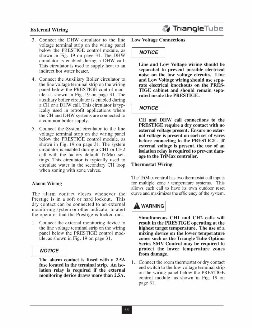
33
External Wiring
3. Connect the DHW circulator to the linevoltage terminal strip on the wiring panelbelow the PRESTIGE control module, asshown in Fig. 19 on page 31. The DHWcirculator is enabled during a DHW call.This circulator is used to supply heat to anindirect hot water heater.
4. Connect the Auxiliary Boiler circulator tothe line voltage terminal strip on the wiringpanel below the PRESTIGE control mod-ule, as shown in Fig. 19 on page 31. Theauxiliary boiler circulator is enabled duringa CH or a DHW call. This circulator is typ-ically used in retrofit applications wherethe CH and DHW systems are connected toa common boiler supply.
5. Connect the System circulator to the linevoltage terminal strip on the wiring panelbelow the PRESTIGE control module, asshown in Fig. 19 on page 31. The systemcirculator is enabled during a CH1 or CH2call with the factory default TriMax set-tings. This circulator is typically used tocirculate water in the secondary CH loopwhen zoning with zone valves.
Alarm Wiring
The alarm contact closes whenever thePrestige is in a soft or hard lockout. Thisdry contact can be connected to an externalmonitoring system or other indicator to alertthe operator that the Prestige is locked out.
1. Connect the external monitoring device tothe line voltage terminal strip on the wiringpanel below the PRESTIGE control mod-ule, as shown in Fig. 19 on page 31.
The alarm contact is fused with a 2.5Afuse located in the terminal strip. An iso-lation relay is required if the externalmonitoring device draws more than 2.5A.
Low Voltage Connections
Line and Low Voltage wiring should beseparated to prevent possible electricalnoise on the low voltage circuits. Lineand Low Voltage wiring should use sepa-rate electrical knockouts on the PRES-TIGE cabinet and should remain sepa-rated inside the PRESTIGE.
CH and DHW call connections to thePRESTIGE require a dry contact with noexternal voltage present. Ensure no exter-nal voltage is present on each set of wiresbefore connecting to the PRESTIGE. Ifexternal voltage is present, the use of anisolation relay is required to prevent dam-age to the TriMax controller.
Thermostat Wiring
The TriMax control has two thermostat call inputsfor multiple zone / temperature systems. Thisallows each call to have its own outdoor resetcurve and maximizes the efficiency of the system.
Simultaneous CH1 and CH2 calls willresult in the PRESTIGE operating at thehighest target temperature. The use of amixing device on the lower temperaturezones such as the Triangle Tube OptimaSeries SMV Control may be required toprotect the lower temperature zonesfrom damage.
1. Connect the room thermostat or dry contactend switch to the low voltage terminal stripon the wiring panel below the PRESTIGEcontrol module, as shown in Fig. 19 onpage 31.
WARNING
NOTICE
NOTICE
NOTICE
34
External Wiring
2. Follow thermostat manufacturer’s instruc-tions for proper installation. Thermostatshould be located on an inside wall awayfrom any heat or cold influences such asdrafts, lights, fireplaces, etc.
3. Set the thermostat anticipator (If applica-ble) as follows:
- Set for 0.2 amps when wired directly tothe PRESTIGE.
- Set to match the electrical powerrequirements of the connected devicewhen wired to zone relays or otherdevices. Refer to the relay manufactur-er’s specifications and the thermostatinstructions for additional informationon anticipator setting.
The use of power stealing thermostatswhich draw their power from the PRES-TIGE can lead to erratic or unpre-dictable operation.
Outdoor Sensor Wiring
The Outdoor Reset function and WarmWeather Shutdown (WWSD) features requirethe connection of the included outdoor temper-ature sensor. See page 63 for outdoor sensorinstallation and setup.
Domestic Hot Water Wiring
The Domestic Hot Water terminals can accepteither a call from an aquastat (switch) or tem-perature sensor. Use of the included indirectwater heater sensor is recommended.
1. Connect the DHW aquastat or temperaturesensor to the low voltage terminal strip onthe wiring panel below the PRESTIGE con-trol module, as shown in Fig. 19 on page 31.
Additional Boiler Limits
Additional boiler limits (High Limit, LWCO,etc.) can be wired into either the Manual ResetLimit or Auto Reset Limit terminals of thePRESTIGE. These limit connections will pro-vide a “hard” lockout requiring a manual resetof the PRESTIGE or a “soft” lockout in whichthe PRESTIGE will automatically reset whenthe limit resets.
Manual Reset Limit and Auto ResetLimit connections to the PRESTIGErequire a dry contact with no externalvoltage present. Ensure no external volt-age is present on each set of wires beforeconnecting to the PRESTIGE. If exter-nal voltage is present, the use of an isola-tion relay is required to prevent damageto the TriMax controller.
1. Remove the factory installed jumper wireon the Manual Reset or Auto Reset termi-nals that will accept the additional boilerlimit.
2. Connect the additional boiler limit to thelow voltage terminal strip on the wiringpanel below the PRESTIGE control mod-ule, as shown in Fig. 19 on page 31.
External Modulation Control
The PRESTIGE firing rate can be controlled byan external modulating boiler controller. Seepage 64 for external modulation signal wiringand setup.
System Sensor Wiring
An optional system temperature sensor can beplaced on the central heating loop to control thetemperature in the central heating loop insteadof the boiler loop. When connected, the PRES-TIGE will automatically modulate to maintainthe target temperature in the central heatingloop. The boiler supply temperature sensorwill continue to be used as a high temperaturelimit.
NOTICE
NOTICE
35
External Wiring
Locate the system temperature sensorwhere it can accurately measure the sup-ply temperature to the heating system.Inaccurate system temperature readingscould lead to overheating or under heat-ing resulting in property damage.
1. Connect the system temperature sensor tothe low voltage terminal strip on the wiringpanel below the PRESTIGE control mod-ule, as shown in Fig. 19 on page 31.
Cascade Wiring
The TriMax control includes the ability tooperate up to six boilers together as one with-out the need for external controllers. Consultthe PRESTIGE TriMax Control Supplementfor more information.
Modbus Wiring
The TriMax control includes the ability tocommunicate with building management sys-tems (BMS) through a Modbus interface.Consult the PRESTIGE TriMax ControlSupplement for more information.
CAUTION
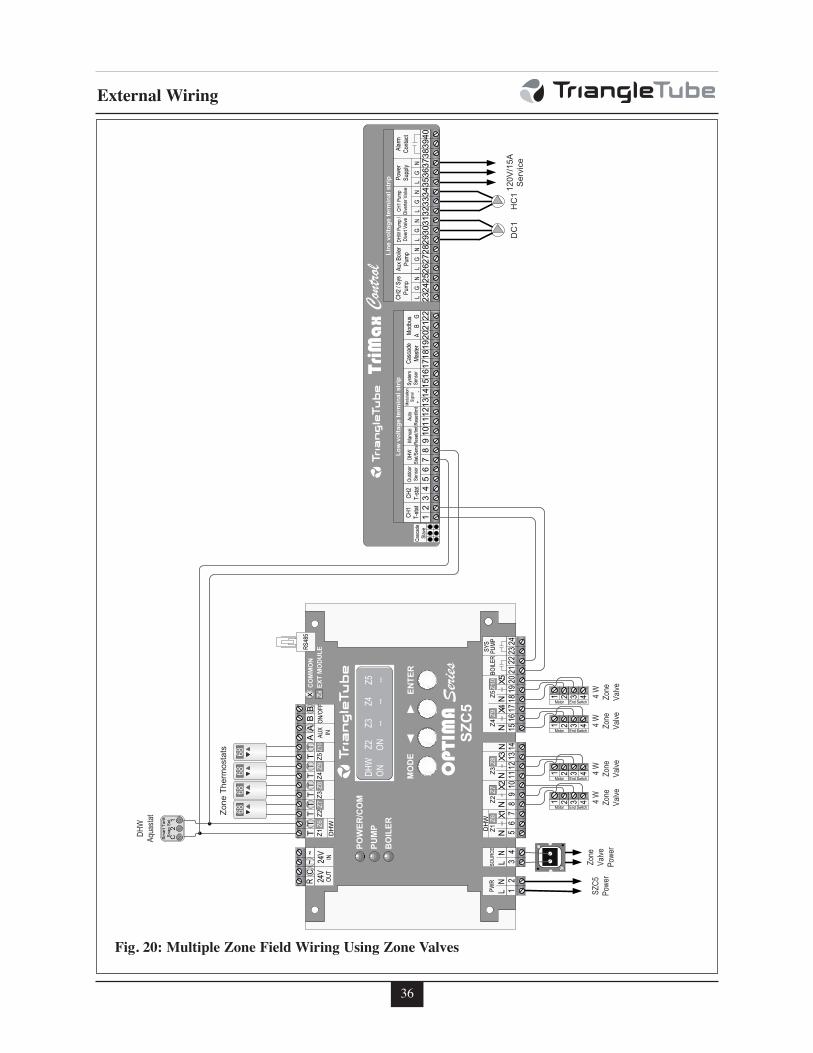
36
External Wiring
Fig. 20: Multiple Zone Field Wiring Using Zone Valves
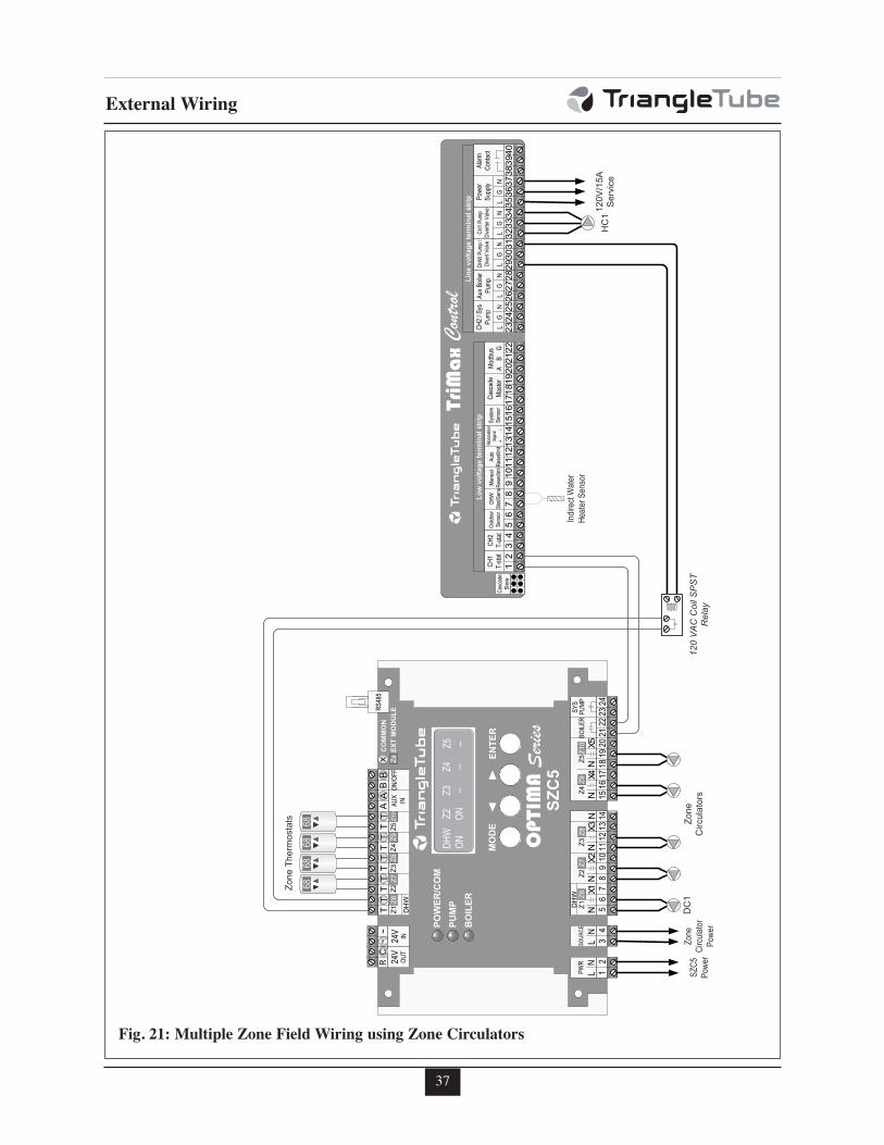
37
External Wiring
Fig. 21: Multiple Zone Field Wiring using Zone Circulators
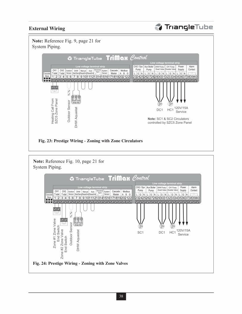
38
External Wiring
Fig. 23: Prestige Wiring - Zoning with Zone Circulators
Fig. 24: Prestige Wiring - Zoning with Zone Valves
Note: Reference Fig. 9, page 21 for
System Piping.
Note: Reference Fig. 10, page 21 for
System Piping.
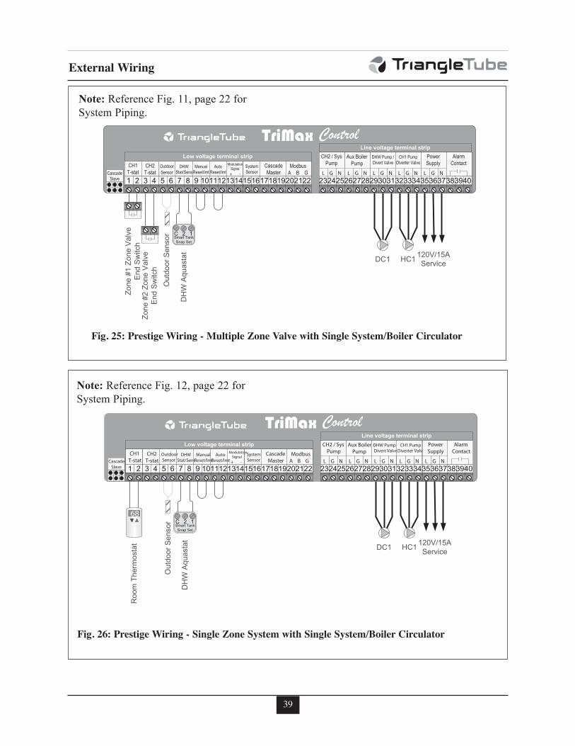
39
External Wiring
DH
W A
quas
tat
Out
door
Sen
sor
Zone
#2Zo
ne V
alve
End
Sw
itch
Zone
# 1Zo
ne V
alve
End
Sw
itch
DC1 HC1 120V/15AService
C 2 1Smart Tank Snap Set
CH1T-stat
5
Low voltage terminal strip
CascadeSlave
CH2T-stat
OutdoorSensor
DHW Stat/Sens
ManualReset/lmt
AutoReset/lmt
Modulation Signal
+ -
SystemSensor
Cascade Master
ModbusA B G
CH2 / Sys Pump
L G N
Aux Boiler Pump
L G N
DHW Pump /Divert Valve
L G N
CH1 Pump Diverter Valve
L G N
Power Supply
L G N
Alarm Contact
Line voltage terminal strip
1 2 3 4 6 7 8 9 10111213141516171819202122 232425262728293031323334353637383940
Fig. 25: Prestige Wiring - Multiple Zone Valve with Single System/Boiler Circulator
DH
W A
quas
tat
Out
door
Sen
sor
Roo
m T
herm
osta
t DC1 HC1 120V/15AService
C 2 1Smart Tank Snap Set
CH1T-stat
5
Low voltage terminal strip
CascadeSlave
CH2T-stat
OutdoorSensor
DHW Stat/Sens
ManualReset/lmt
AutoReset/lmt
Modulation Signal
+ -
SystemSensor
Cascade Master
ModbusA B G
CH2 / Sys Pump
L G N
Aux Boiler Pump
L G N
DHW Pump /Divert Valve
L G N
CH1 Pump Diverter Valve
L G N
Power Supply
L G N
Alarm Contact
Line voltage terminal strip
1 2 3 4 6 7 8 9 10111213141516171819202122 232425262728293031323334353637383940
68
Fig. 26: Prestige Wiring - Single Zone System with Single System/Boiler Circulator
Note: Reference Fig. 11, page 22 for
System Piping.
Note: Reference Fig. 12, page 22 for
System Piping.
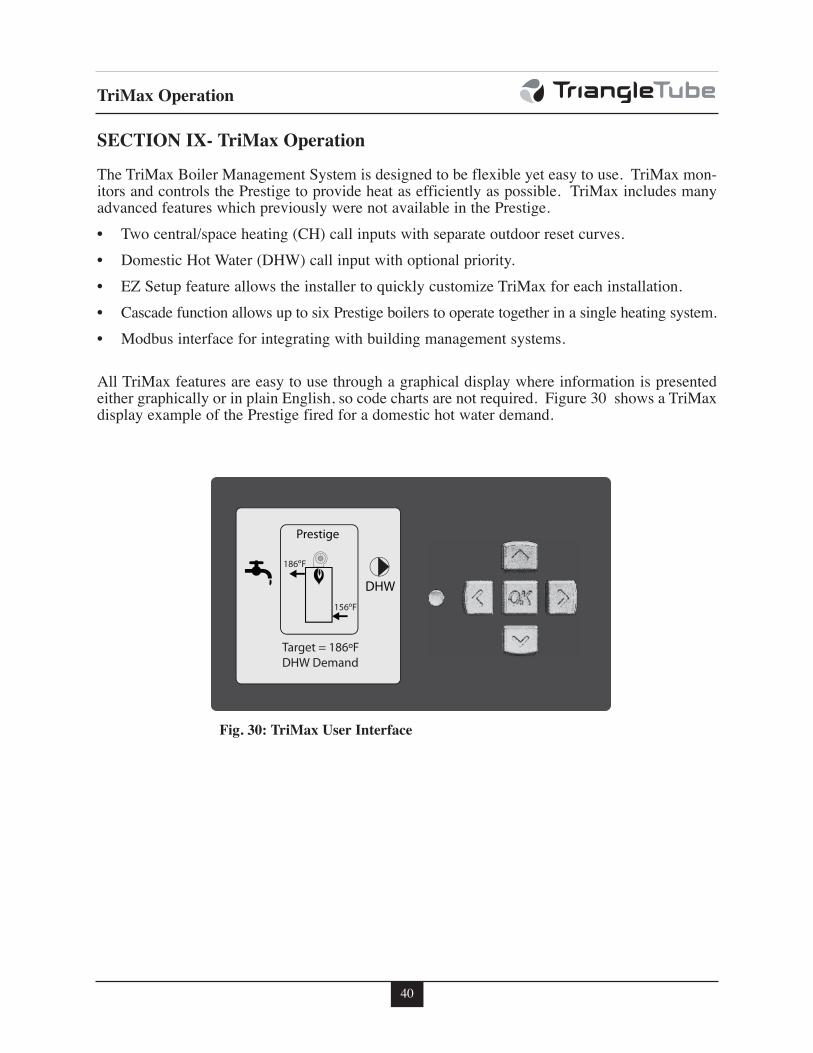
40
TriMax Operation
SECTION IX- TriMax Operation
The TriMax Boiler Management System is designed to be flexible yet easy to use. TriMax mon-itors and controls the Prestige to provide heat as efficiently as possible. TriMax includes manyadvanced features which previously were not available in the Prestige.
• Two central/space heating (CH) call inputs with separate outdoor reset curves.
• Domestic Hot Water (DHW) call input with optional priority.
• EZ Setup feature allows the installer to quickly customize TriMax for each installation.
• Cascade function allows up to six Prestige boilers to operate together in a single heating system.
• Modbus interface for integrating with building management systems.
All TriMax features are easy to use through a graphical display where information is presentedeither graphically or in plain English, so code charts are not required. Figure 30 shows a TriMaxdisplay example of the Prestige fired for a domestic hot water demand.
Fig. 30: TriMax User Interface
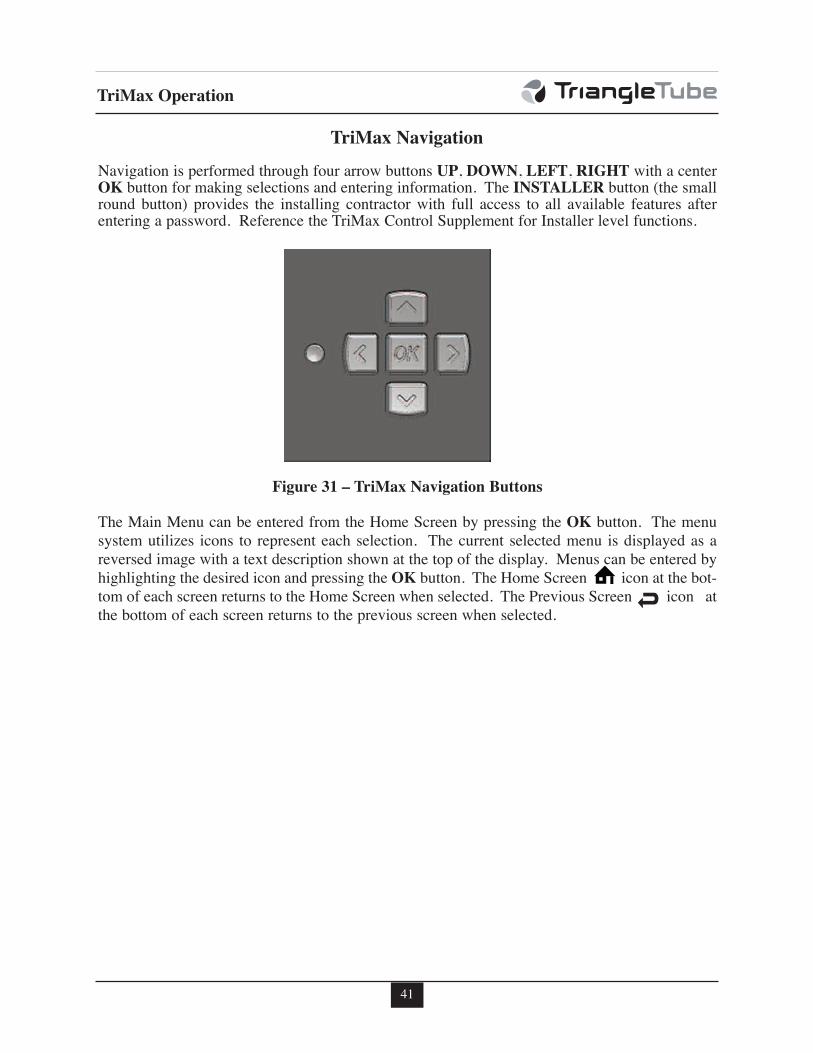
41
TriMax Operation
TriMax Navigation
Navigation is performed through four arrow buttons UP, DOWN, LEFT, RIGHT with a centerOK button for making selections and entering information. The INSTALLER button (the smallround button) provides the installing contractor with full access to all available features afterentering a password. Reference the TriMax Control Supplement for Installer level functions.
Figure 31 – TriMax Navigation Buttons
The Main Menu can be entered from the Home Screen by pressing the OK button. The menusystem utilizes icons to represent each selection. The current selected menu is displayed as areversed image with a text description shown at the top of the display. Menus can be entered byhighlighting the desired icon and pressing the OK button. The Home Screen icon at the bot-tom of each screen returns to the Home Screen when selected. The Previous Screen icon atthe bottom of each screen returns to the previous screen when selected.
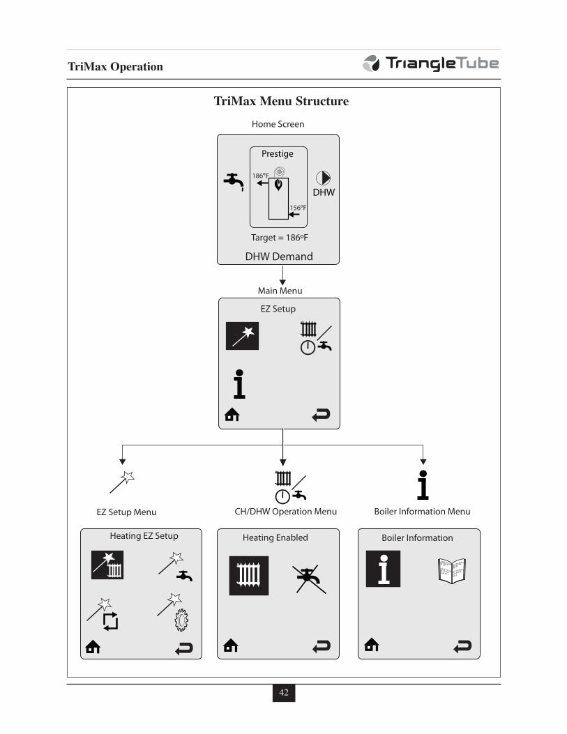
42
TriMax Operation
abc de f bbb b
abc de f bb
abc de
abc de f bbb b
abc de f bb
abc d
abc de f bbb b
abc de f bbabc de
abc de f bbb b
abc de f bb
f bg abc d
Boiler Information
Boiler Information MenuCH/DHW Operation MenuEZ Setup Menu
Main Menu
Home Screen
Heating Enabled
TriMax Menu Structure
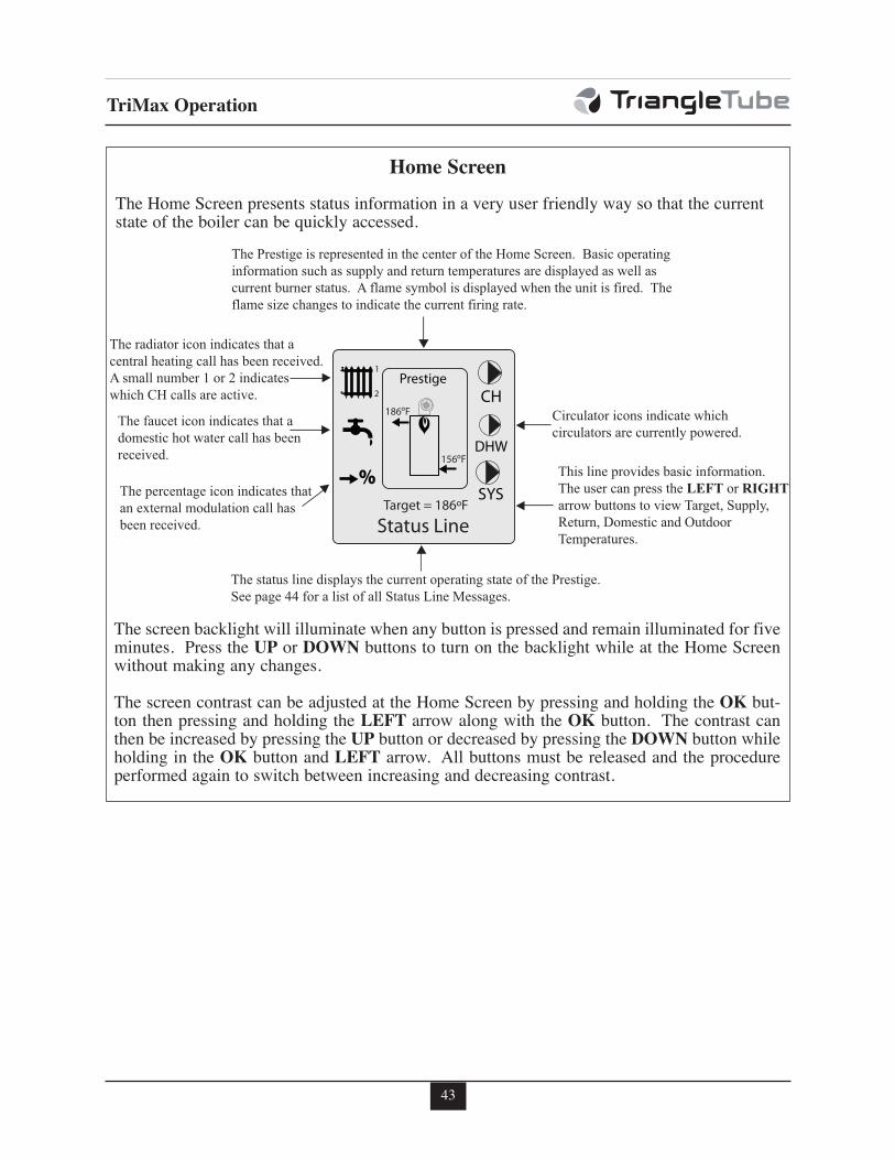
43
TriMax Operation
The status line displays the current operating state of the Prestige.See page 44 for a list of all Status Line Messages.
The radiator icon indicates that a central heating call has been received.A small number 1 or 2 indicateswhich CH calls are active.
Circulator icons indicate which circulators are currently powered.
The faucet icon indicates that a domestic hot water call has beenreceived.
The percentage icon indicates that an external modulation call has been received.
This line provides basic information. The user can press the LEFT or RIGHT arrow buttons to view Target, Supply, Return, Domestic and Outdoor Temperatures.
The Prestige is represented in the center of the Home Screen. Basic operating information such as supply and return temperatures are displayed as well as current burner status. A flame symbol is displayed when the unit is fired. The flame size changes to indicate the current firing rate.
1
2
Home Screen
The Home Screen presents status information in a very user friendly way so that the currentstate of the boiler can be quickly accessed.
The screen backlight will illuminate when any button is pressed and remain illuminated for fiveminutes. Press the UP or DOWN buttons to turn on the backlight while at the Home Screenwithout making any changes.
The screen contrast can be adjusted at the Home Screen by pressing and holding the OK but-ton then pressing and holding the LEFT arrow along with the OK button. The contrast canthen be increased by pressing the UP button or decreased by pressing the DOWN button whileholding in the OK button and LEFT arrow. All buttons must be released and the procedureperformed again to switch between increasing and decreasing contrast.
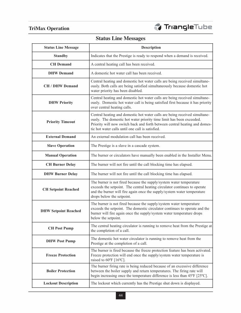
44
TriMax Operation
Status Line Messages
Status Line Message Description
Standby Indicates that the Prestige is ready to respond when a demand is received.
CH Demand A central heating call has been received.
DHW Demand A domestic hot water call has been received.
CH / DHW Demand
Central heating and domestic hot water calls are being received simultane-
ously. Both calls are being satisfied simultaneously because domestic hot
water priority has been disabled.
DHW Priority
Central heating and domestic hot water calls are being received simultane-
ously. Domestic hot water call is being satisfied first because it has priority
over central heating calls.
Priority Timeout
Central heating and domestic hot water calls are being received simultane-
ously. The domestic hot water priority time limit has been exceeded.
Priority will now switch back and forth between central heating and domes-
tic hot water calls until one call is satisfied.
External Demand An external modulation call has been received.
Slave Operation The Prestige is a slave in a cascade system.
Manual Operation The burner or circulators have manually been enabled in the Installer Menu.
CH Burner Delay The burner will not fire until the call blocking time has elapsed.
DHW Burner Delay The burner will not fire until the call blocking time has elapsed.
CH Setpoint Reached
The burner is not fired because the supply/system water temperature
exceeds the setpoint. The central heating circulator continues to operate
and the burner will fire again once the supply/system water temperature
drops below the setpoint.
DHW Setpoint Reached
The burner is not fired because the supply/system water temperature
exceeds the setpoint. The domestic circulator continues to operate and the
burner will fire again once the supply/system water temperature drops
below the setpoint.
CH Post PumpThe central heating circulator is running to remove heat from the Prestige at
the completion of a call.
DHW Post PumpThe domestic hot water circulator is running to remove heat from the
Prestige at the completion of a call.
Freeze Protection
The burner is fired because the freeze protection feature has been activated.
Freeze protection will end once the supply/system water temperature is
raised to 60ºF [16ºC].
Boiler Protection
The burner firing rate is being reduced because of an excessive difference
between the boiler supply and return temperatures. The firing rate will
begin increasing once the temperature difference is less than 45ºF [25ºC].
Lockout Description The lockout which currently has the Prestige shut down is displayed.
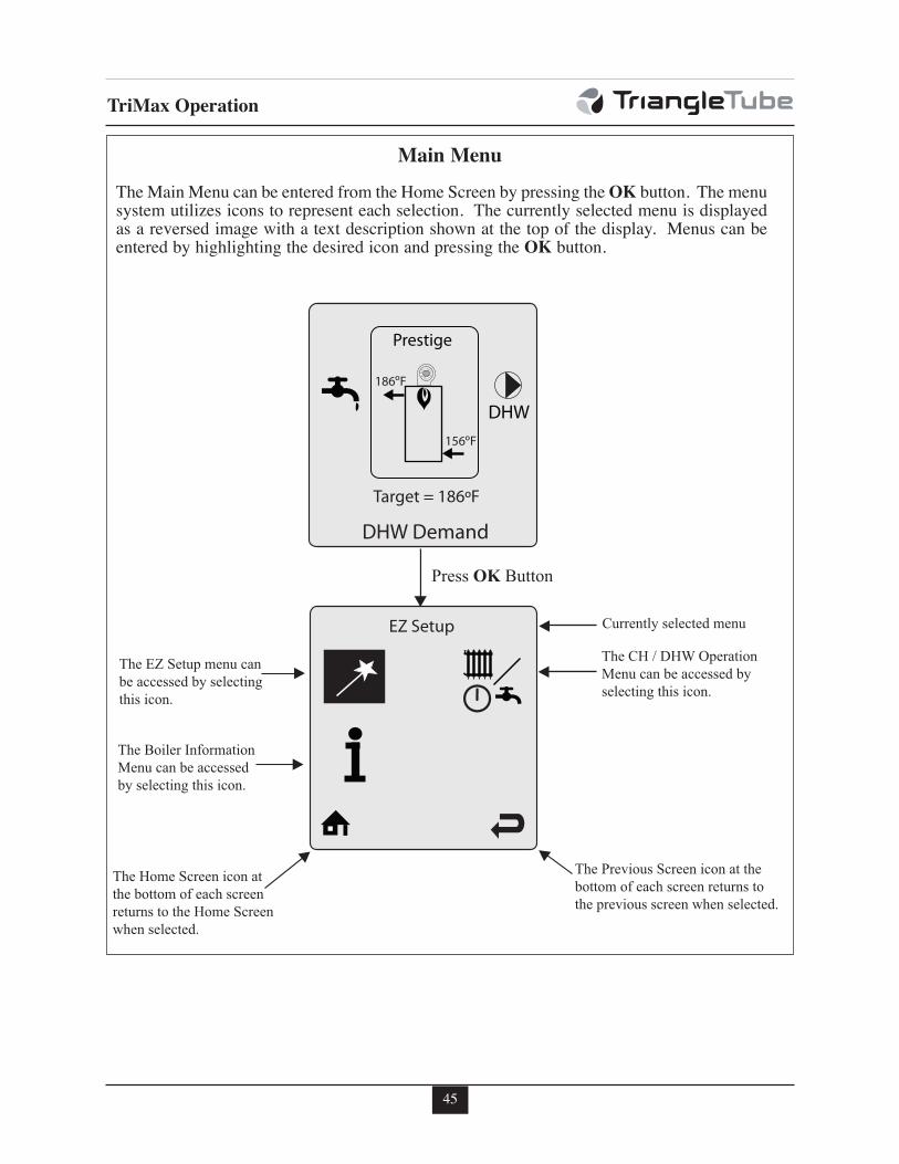
45
TriMax Operation
Press OK Button
The EZ Setup menu canbe accessed by selectingthis icon.
The CH / DHW Operation Menu can be accessed by selecting this icon.
Currently selected menu
The Boiler InformationMenu can be accessed by selecting this icon.
The Home Screen icon at the bottom of each screen returns to the Home Screen when selected.
The Previous Screen icon at thebottom of each screen returns to the previous screen when selected.
Main Menu
The Main Menu can be entered from the Home Screen by pressing the OK button. The menusystem utilizes icons to represent each selection. The currently selected menu is displayedas a reversed image with a text description shown at the top of the display. Menus can beentered by highlighting the desired icon and pressing the OK button.
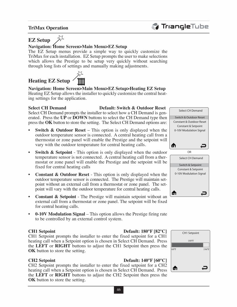
46
TriMax Operation
EZ Setup Navigation: Home Screen>Main Menu>EZ SetupThe EZ Setup menus provide a simple way to quickly customize theTriMax for each installation. EZ Setup prompts the user to make selectionswhich allows the Prestige to be setup very quickly without searchingthrough long lists of settings and manually making adjustments.
Heating EZ Setup
Navigation: Home Screen>Main Menu>EZ Setup>Heating EZ SetupHeating EZ Setup allows the installer to quickly customize the central heat-ing settings for the application.
Select CH Demand Default: Switch & Outdoor ResetSelect CH Demand prompts the installer to select how a CH Demand is gen-erated. Press the UP or DOWN buttons to select the CH Demand type thenpress the OK button to store the setting. The Select CH Demand options are:
• Switch & Outdoor Reset – This option is only displayed when theoutdoor temperature sensor is connected. A central heating call from athermostat or zone panel will enable the Prestige and the setpoint willvary with the outdoor temperature for central heating calls.
• Switch & Setpoint - This option is only displayed when the outdoortemperature sensor is not connected. A central heating call from a ther-mostat or zone panel will enable the Prestige and the setpoint will befixed for central heating calls
• Constant & Outdoor Reset - This option is only displayed when theoutdoor temperature sensor is connected. The Prestige will maintain set-point without an external call from a thermostat or zone panel. The set-point will vary with the outdoor temperature for central heating calls.
• Constant & Setpoint - The Prestige will maintain setpoint without anexternal call from a thermostat or zone panel. The setpoint will be fixedfor central heating calls.
• 0-10V Modulation Signal – This option allows the Prestige firing rateto be controlled by an external control system.
CH1 Setpoint Default: 180°F [82°C]CH1 Setpoint prompts the installer to enter the fixed setpoint for a CH1heating call when a Setpoint option is chosen in Select CH Demand. Pressthe LEFT or RIGHT buttons to adjust the CH1 Setpoint then press theOK button to store the setting.
CH2 Setpoint Default: 140°F [60°C]CH2 Setpoint prompts the installer to enter the fixed setpoint for a CH2heating call when a Setpoint option is chosen in Select CH Demand. Pressthe LEFT or RIGHT buttons to adjust the CH2 Setpoint then press theOK button to store the setting.
Select CH Demand
Switch & Outdoor ResetConstant & Outdoor Reset
Constant & Setpoint0-10V Modulation Signal
Switch & Outdoor Reset
Select CH Demand
Switch & SetpointConstant & Setpoint
0-10V Modulation Signal
OR
Switch & Setpoint
68ºF 194ºF
180ºF
CH1 Setpoint
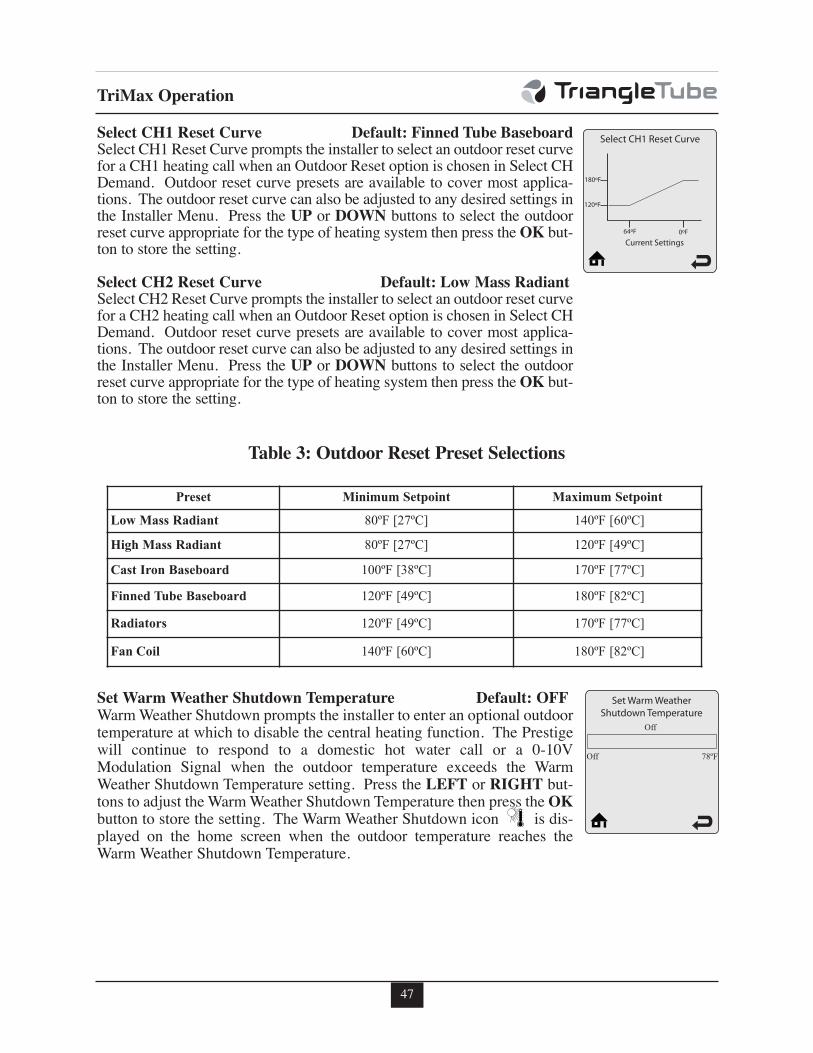
47
TriMax Operation
Select CH1 Reset Curve Default: Finned Tube BaseboardSelect CH1 Reset Curve prompts the installer to select an outdoor reset curvefor a CH1 heating call when an Outdoor Reset option is chosen in Select CHDemand. Outdoor reset curve presets are available to cover most applica-tions. The outdoor reset curve can also be adjusted to any desired settings inthe Installer Menu. Press the UP or DOWN buttons to select the outdoorreset curve appropriate for the type of heating system then press the OK but-ton to store the setting.
Select CH2 Reset Curve Default: Low Mass RadiantSelect CH2 Reset Curve prompts the installer to select an outdoor reset curvefor a CH2 heating call when an Outdoor Reset option is chosen in Select CHDemand. Outdoor reset curve presets are available to cover most applica-tions. The outdoor reset curve can also be adjusted to any desired settings inthe Installer Menu. Press the UP or DOWN buttons to select the outdoorreset curve appropriate for the type of heating system then press the OK but-ton to store the setting.
Set Warm Weather Shutdown Temperature Default: OFFWarm Weather Shutdown prompts the installer to enter an optional outdoortemperature at which to disable the central heating function. The Prestigewill continue to respond to a domestic hot water call or a 0-10VModulation Signal when the outdoor temperature exceeds the WarmWeather Shutdown Temperature setting. Press the LEFT or RIGHT but-tons to adjust the Warm Weather Shutdown Temperature then press the OKbutton to store the setting. The Warm Weather Shutdown icon is dis-played on the home screen when the outdoor temperature reaches theWarm Weather Shutdown Temperature.
180ºF
120ºF
64ºF 0ºF
Current Settings
Table 3: Outdoor Reset Preset Selections
Preset Minimum Setpoint Maximum Setpoint
Low Mass Radiant 80ºF [27ºC] 140ºF [60ºC]
High Mass Radiant 80ºF [27ºC] 120ºF [49ºC]
Cast Iron Baseboard 100ºF [38ºC] 170ºF [77ºC]
Finned Tube Baseboard 120ºF [49ºC] 180ºF [82ºC]
Radiators 120ºF [49ºC] 170ºF [77ºC]
Fan Coil 140ºF [60ºC] 180ºF [82ºC]
Off 78ºF
Off
Set Warm Weather Shutdown Temperature
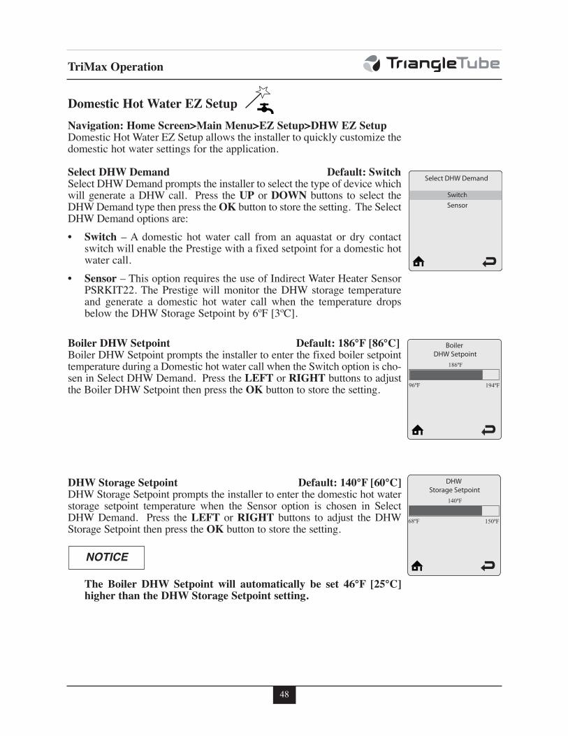
48
TriMax Operation
Navigation: Home Screen>Main Menu>EZ Setup>DHW EZ SetupDomestic Hot Water EZ Setup allows the installer to quickly customize thedomestic hot water settings for the application.
Select DHW Demand Default: SwitchSelect DHW Demand prompts the installer to select the type of device whichwill generate a DHW call. Press the UP or DOWN buttons to select theDHW Demand type then press the OK button to store the setting. The SelectDHW Demand options are:
• Switch – A domestic hot water call from an aquastat or dry contactswitch will enable the Prestige with a fixed setpoint for a domestic hotwater call.
• Sensor – This option requires the use of Indirect Water Heater SensorPSRKIT22. The Prestige will monitor the DHW storage temperatureand generate a domestic hot water call when the temperature dropsbelow the DHW Storage Setpoint by 6ºF [3ºC].
Boiler DHW Setpoint Default: 186°F [86°C]Boiler DHW Setpoint prompts the installer to enter the fixed boiler setpointtemperature during a Domestic hot water call when the Switch option is cho-sen in Select DHW Demand. Press the LEFT or RIGHT buttons to adjustthe Boiler DHW Setpoint then press the OK button to store the setting.
DHW Storage Setpoint Default: 140°F [60°C]DHW Storage Setpoint prompts the installer to enter the domestic hot waterstorage setpoint temperature when the Sensor option is chosen in SelectDHW Demand. Press the LEFT or RIGHT buttons to adjust the DHWStorage Setpoint then press the OK button to store the setting.
The Boiler DHW Setpoint will automatically be set 46°F [25°C]higher than the DHW Storage Setpoint setting.
NOTICE
Domestic Hot Water EZ Setup
Select DHW Demand
SwitchSensorSwitch
96ºF 194ºF
186ºF
Boiler DHW Setpoint
68ºF 150ºF
140ºF
DHW Storage Setpoint
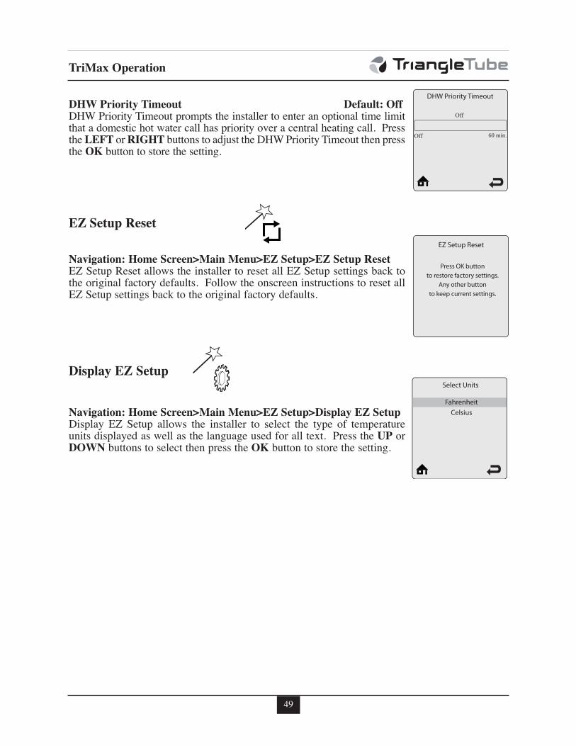
49
TriMax Operation
DHW Priority Timeout Default: OffDHW Priority Timeout prompts the installer to enter an optional time limitthat a domestic hot water call has priority over a central heating call. Pressthe LEFT or RIGHT buttons to adjust the DHW Priority Timeout then pressthe OK button to store the setting.
Navigation: Home Screen>Main Menu>EZ Setup>EZ Setup ResetEZ Setup Reset allows the installer to reset all EZ Setup settings back tothe original factory defaults. Follow the onscreen instructions to reset allEZ Setup settings back to the original factory defaults.
Navigation: Home Screen>Main Menu>EZ Setup>Display EZ SetupDisplay EZ Setup allows the installer to select the type of temperatureunits displayed as well as the language used for all text. Press the UP orDOWN buttons to select then press the OK button to store the setting.
Off 60 min.
Off
DHW Priority Timeout
EZ Setup Reset
EZ Setup Reset
Press OK buttonto restore factory settings.
Any other buttonto keep current settings.
Display EZ Setup
Select Units
FahrenheitCelsius
Fahrenheit
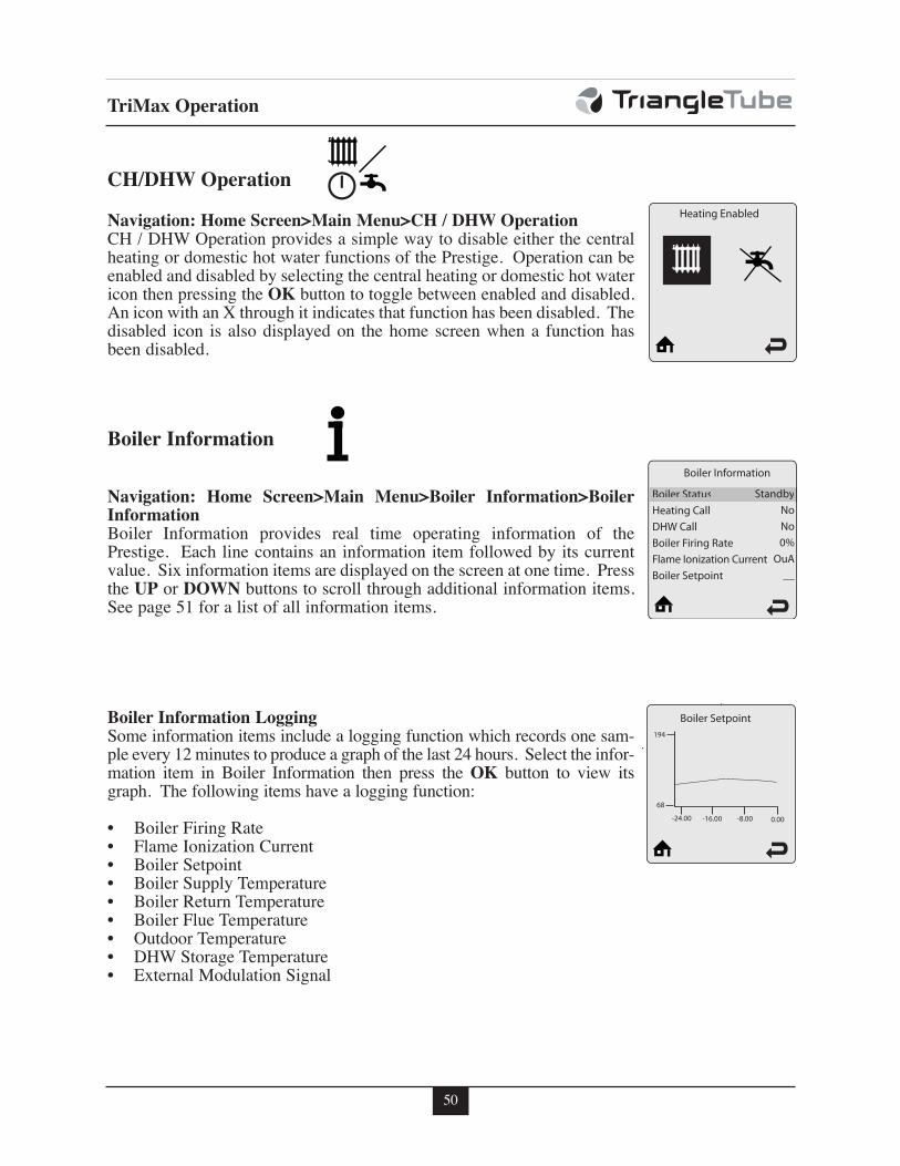
50
TriMax Operation
CH/DHW Operation
Heating EnabledNavigation: Home Screen>Main Menu>CH / DHW OperationCH / DHW Operation provides a simple way to disable either the centralheating or domestic hot water functions of the Prestige. Operation can beenabled and disabled by selecting the central heating or domestic hot watericon then pressing the OK button to toggle between enabled and disabled.An icon with an X through it indicates that function has been disabled. Thedisabled icon is also displayed on the home screen when a function hasbeen disabled.
Navigation: Home Screen>Main Menu>Boiler Information>BoilerInformationBoiler Information provides real time operating information of thePrestige. Each line contains an information item followed by its currentvalue. Six information items are displayed on the screen at one time. Pressthe UP or DOWN buttons to scroll through additional information items.See page 51 for a list of all information items.
Boiler Information LoggingSome information items include a logging function which records one sam-ple every 12 minutes to produce a graph of the last 24 hours. Select the infor-mation item in Boiler Information then press the OK button to view itsgraph. The following items have a logging function:
• Boiler Firing Rate• Flame Ionization Current• Boiler Setpoint• Boiler Supply Temperature• Boiler Return Temperature• Boiler Flue Temperature• Outdoor Temperature• DHW Storage Temperature• External Modulation Signal
Boiler Information
Boiler Information
Boiler StatusHeating CallDHW CallBoiler Firing RateFlame Ionization CurrentBoiler Setpoint
StandbyNoNo0%
OuA__
Boiler Status Standby
194
68
-24.00 -16.00 -8.00 0.00
Boiler Setpoint
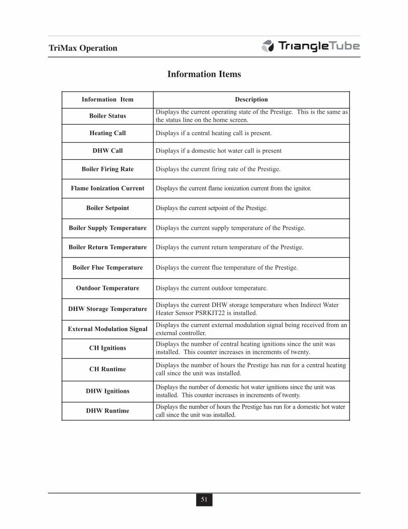
51
TriMax Operation
Information Item Description
Boiler StatusDisplays the current operating state of the Prestige. This is the same as
the status line on the home screen.
Heating Call Displays if a central heating call is present.
DHW Call Displays if a domestic hot water call is present
Boiler Firing Rate Displays the current firing rate of the Prestige.
Flame Ionization Current Displays the current flame ionization current from the ignitor.
Boiler Setpoint Displays the current setpoint of the Prestige.
Boiler Supply Temperature Displays the current supply temperature of the Prestige.
Boiler Return Temperature Displays the current return temperature of the Prestige.
Boiler Flue Temperature Displays the current flue temperature of the Prestige.
Outdoor Temperature Displays the current outdoor temperature.
DHW Storage TemperatureDisplays the current DHW storage temperature when Indirect Water
Heater Sensor PSRKIT22 is installed.
External Modulation SignalDisplays the current external modulation signal being received from an
external controller.
CH IgnitionsDisplays the number of central heating ignitions since the unit was
installed. This counter increases in increments of twenty.
CH RuntimeDisplays the number of hours the Prestige has run for a central heating
call since the unit was installed.
DHW IgnitionsDisplays the number of domestic hot water ignitions since the unit was
installed. This counter increases in increments of twenty.
DHW RuntimeDisplays the number of hours the Prestige has run for a domestic hot water
call since the unit was installed.
Information Items
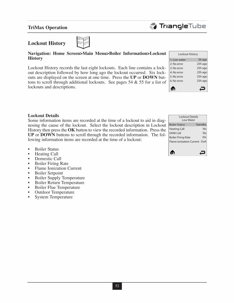
52
TriMax Operation
Navigation: Home Screen>Main Menu>Boiler Information>LockoutHistory
Lockout History records the last eight lockouts. Each line contains a lock-out description followed by how long ago the lockout occurred. Six lock-outs are displayed on the screen at one time. Press the UP or DOWN but-tons to scroll through additional lockouts. See pages 54 & 55 for a list oflockouts and descriptions.
Lockout DetailsSome information items are recorded at the time of a lockout to aid in diag-nosing the cause of the lockout. Select the lockout description in LockoutHistory then press the OK button to view the recorded information. Press theUP or DOWN buttons to scroll through the recorded information. The fol-lowing information items are recorded at the time of a lockout:
• Boiler Status• Heating Call• Domestic Call• Boiler Firing Rate• Flame Ionization Current• Boiler Setpoint• Boiler Supply Temperature• Boiler Return Temperature• Boiler Flue Temperature• Outdoor Temperature• System Temperature
Lockout History
Lockout History
1: Low water2: No error3: No error4: No error5: No error6: No error
5h ago25h ago25h ago25h ago25h ago25h ago
1: Low water 5h ago
Lockout DetailsLow Water
Boiler StatusHeating CallDHW CallBoiler Firing RateFlame ionization Current
StandbyNoNo0%
OuA
Boiler Status Standby
abc de f bbb b
abc de f bb
abc de
abc de f bbb b
abc de f bb
abc d
abc de f bbb b
abc de f bbabc de
abc de f bbb b
abc de f bb
f bg abc d
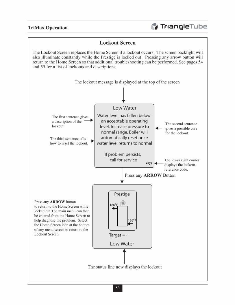
53
TriMax Operation
Press any ARROW Button
The status line now displays the lockout
The lockout message is displayed at the top of the screen
The lower right cornerdisplays the lockoutreference code.
The second sentence gives a possible cure for the lockout.
The first sentence givesa description of the lockout.
The third sentence tells how to reset the lockout.
Press any ARROW buttonto return to the Home Screen whilelocked out.The main menu can thenbe entered from the Home Screen to help diagnose the problem. Selectthe Home Screen icon at the bottomof any menu screen to return to the Lockout Screen.
Water level has fallen below an acceptable operating
level. Increase pressure to normal range. Boiler will automatically reset once
water level returns to normal
Low Water
If problem persists, call for service
E37
--
Lockout Screen
The Lockout Screen replaces the Home Screen if a lockout occurs. The screen backlight willalso illuminate constantly while the Prestige is locked out. Pressing any arrow button willreturn to the Home Screen so that additional troubleshooting can be performed. See pages 54and 55 for a list of lockouts and descriptions.
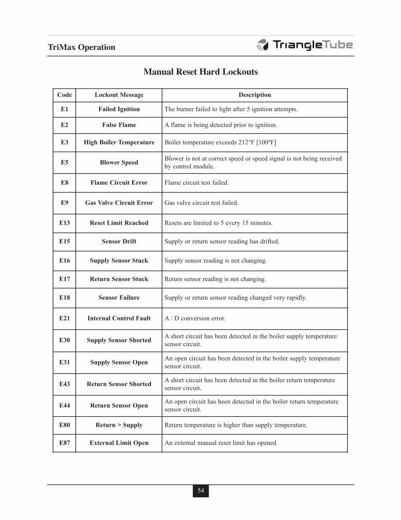
54
TriMax Operation
Manual Reset Hard Lockouts
Code Lockout Message Description
E1 Failed Ignition The burner failed to light after 5 ignition attempts.
E2 False Flame A flame is being detected prior to ignition.
E3 High Boiler Temperature Boiler temperature exceeds 212°F [100ºF]
E5 Blower SpeedBlower is not at correct speed or speed signal is not being received
by control module.
E8 Flame Circuit Error Flame circuit test failed.
E9 Gas Valve Circuit Error Gas valve circuit test failed.
E13 Reset Limit Reached Resets are limited to 5 every 15 minutes.
E15 Sensor Drift Supply or return sensor reading has drifted.
E16 Supply Sensor Stuck Supply sensor reading is not changing.
E17 Return Sensor Stuck Return sensor reading is not changing.
E18 Sensor Failure Supply or return sensor reading changed very rapidly.
E21 Internal Control Fault A / D conversion error.
E30 Supply Sensor ShortedA short circuit has been detected in the boiler supply temperature
sensor circuit.
E31 Supply Sensor OpenAn open circuit has been detected in the boiler supply temperature
sensor circuit.
E43 Return Sensor ShortedA short circuit has been detected in the boiler return temperature
sensor circuit.
E44 Return Sensor OpenAn open circuit has been detected in the boiler return temperature
sensor circuit.
E80 Return > Supply Return temperature is higher than supply temperature.
E87 External Limit Open An external manual reset limit has opened
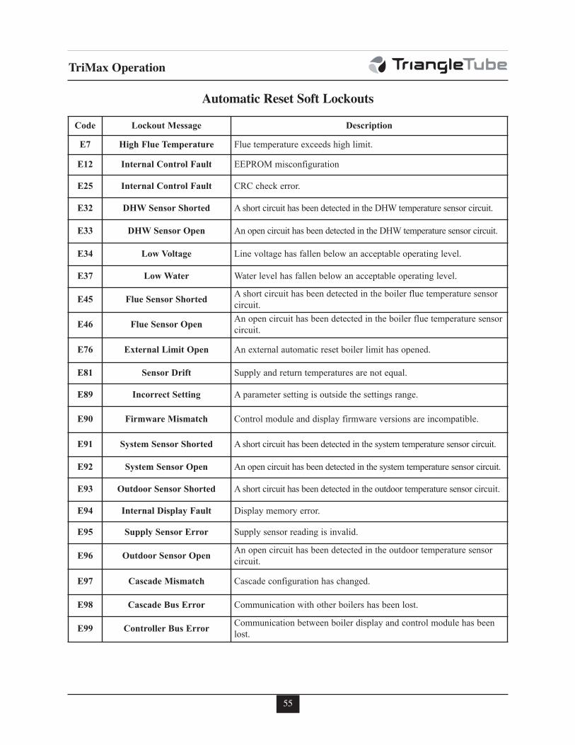
55
TriMax Operation
Automatic Reset Soft Lockouts
Code Lockout Message Description
E7 High Flue Temperature Flue temperature exceeds high limit.
E12 Internal Control Fault EEPROM misconfiguration
E25 Internal Control Fault CRC check error.
E32 DHW Sensor Shorted A short circuit has been detected in the DHW temperature sensor circuit.
E33 DHW Sensor Open An open circuit has been detected in the DHW temperature sensor circuit.
E34 Low Voltage Line voltage has fallen below an acceptable operating level.
E37 Low Water Water level has fallen below an acceptable operating level.
E45 Flue Sensor ShortedA short circuit has been detected in the boiler flue temperature sensor
circuit.
E46 Flue Sensor OpenAn open circuit has been detected in the boiler flue temperature sensor
circuit.
E76 External Limit Open An external automatic reset boiler limit has opened.
E81 Sensor Drift Supply and return temperatures are not equal.
E89 Incorrect Setting A parameter setting is outside the settings range.
E90 Firmware Mismatch Control module and display firmware versions are incompatible.
E91 System Sensor Shorted A short circuit has been detected in the system temperature sensor circuit.
E92 System Sensor Open An open circuit has been detected in the system temperature sensor circuit.
E93 Outdoor Sensor Shorted A short circuit has been detected in the outdoor temperature sensor circuit.
E94 Internal Display Fault Display memory error.
E95 Supply Sensor Error Supply sensor reading is invalid.
E96 Outdoor Sensor OpenAn open circuit has been detected in the outdoor temperature sensor
circuit.
E97 Cascade Mismatch Cascade configuration has changed.
E98 Cascade Bus Error Communication with other boilers has been lost.
E99 Controller Bus ErrorCommunication between boiler display and control module has been
lost.
56
Start-Up Preparation
SECTION X - Start-Up Preparation
Requirements below must be met forwarranty coverage of Prestige heatexchangers. A thorough cleaning of anyexisting system, using approved heatingsystem cleaning agents is required priorto installation of the Prestige boiler.System should be treated with anapproved inhibitor after filling for longterm protection.
Check Boiler System Water Chemistry
Do not use petroleum-based cleaning orsealing compounds in the boiler system.Damage to seals and gaskets in the sys-tem components could occur, resulting insubstantial property damage.
System water including additives must bepractically non-toxic, having a toxicityrating or Class of 1, as listed in ClinicalToxicology of Commercial Products.
Water pH Level 6.0 to 8.0
Maintain the boiler water pH between 6.0 and8.0. Check using litmus paper or contact a watertreatment company for a chemical analysis.
If the pH does not meet this requirement, donot operate the PRESTIGE Solo or leave theunit filled until the condition is corrected.
Water Hardness Less Than 7 Grains
For areas with unusually hard water (hardnessabove 7 grains) consult a water treatmentcompany.
Chlorinated Water
Do not use the PRESTIGE Solo to heat aswimming pool or spa directly.
Maintain the chlorine level of the water at lev-els considered safe for drinking.
Flush Boiler to Remove Sediment
The installer must flush the boiler system toremove any sediment to allow proper operationof the PRESTIGE Solo .
Flush the systems until the water runs cleanand is free of sediment.
For zoned systems, each zone should beflushed through a purge valve. Purge valvesand isolation valves should be installed on eachzone to allow proper flushing of the system.
Cleaning of Old Boiler/System:
• Drain the existing system.
• Fill system with fresh water and cleaner,place existing boiler in operation and runall zones.
• Follow manufacturer’s instructions forproper cleaner concentration and propercleaning time.
• Thoroughly drain and flush system withfresh water after cleaning.
• Install new boiler, fill system with freshwater and proper amount of inhibitor.
• Verify pH and inhibitor level per inhibitormanufacturer’s specs; add inhibitor ifnecessary.
Cleaning of New Boiler/System:
• Install new boiler and flush system withcleaner water to remove any debris.
• Fill system with fresh water and properamount of inhibitor.
• Verify pH and inhibitor level per inhibitormanufacturer’s specs; add inhibitor ifnecessary.
NOTICE
WARNING
NOTICE
57
Start-Up Preparation
Check and Test Antifreeze
For boiler systems containing antifreeze solu-tions, follow the antifreeze manufacturer’sinstructions in verifying the inhibitor level andto ensure the fluid characteristics are withinspecification requirements.
Due to the degradation of inhibitors over time,antifreeze fluids must be periodically replaced.Refer to the manufacturer of the antifreeze foradditional instructions.
Use of Antifreeze in the Boiler System
NEVER use automotive or ethylene glycolantifreeze or undiluted antifreeze in theprimary system as freeze protection. Thiscan cause severe personal injury, death orsubstantial property damage if ignored.
Determine the antifreeze fluid quantity usingthe system water content volume and followingthe antifreeze manufacturer instructions.
The water volume of the PRESTIGE Solo isapproximately 3 gallons [12 L] for PRESTIGESolo 60 or 5 gallons [19 L] for PRESTIGE Solo175/250 or 7 gallons [26 L] for PRESTIGE Solo399 . Remember to include the volume of theexpansion tank.
Check with local codes requirements for theinstallation of backflow preventers or actualdisconnection from the boiler’s cold water fillor make up water supply line.
Massachusetts Code requires the instal-lation of a backflow preventer ifantifreeze is used.
Ensure the concentration of antifreeze to waterdoes not exceed a 50/50 ratio.
System water, including additives, mustbe practically non-toxic, having a toxicityrating or Class of 1, as listed in ClinicalToxicology of Commercial Products.
Filling the Boiler System
1. Close the boiler drain valve located on thebottom of the unit and any manual or auto-matic air vent in the system.
2. Open all system isolation valves.
3. Fill the boiler system to correct systempressure. Correct pressure will vary witheach application.
Typical residential system fill pressure is12 psi. System pressure will increasewhen system temperature increases.Operating pressure of the system shouldnever exceed 25 psi.
4. Purge air and sediment in each zone of theboiler system through the purge valve.Open air vents to allow air to be purged inthe zones.
5. Once the system is completely filled andpurged of all air and sediment, check thesystem pressure and check/repair any leaks.
Unrepaired system leaks will cause con-tinual makeup water to be added to theboiler. Continual makeup water willcause mineral buildup within the heatexchanger, reducing the heat transfer,causing possible heat buildup and even-tual heat exchanger failure.
Check Low Water Cut-Off Device
- The PRESTIGE Solo is provided with afactory installed LWCO device that mea-sures system pressure of more than 10 psi.
NOTICE
NOTICE
WARNING
NOTICE
WARNING
58
Start-Up Preparation
- Remove the front jacket panel and check forcontinuity across the low water cut-off devicewire terminals. The contacts should be closedwhen system pressure is greater than 10 psi.See item 6, on Fig. 36 page 78(PRESTIGESolo 60) or on Fig. 37 page 79 (PRESTIGESolo 175/250) or Fig. 38 page 80 (PRESTIGESolo 399) for location of the LWCO.
Check For Gas Leaks
Prior to start-up and during initial opera-tion, smell near the floor and around theunit for gas odorant or any unusual odor.Do not proceed with the start-up if thereis any indication of a gas leak. Any leaksfound must be repaired immediately.
Propane installations only - The propanesupplier mixes an odorant with thepropane to make its presence detectable.In some cases the odorant can fade andthe gas may no longer have an odor.
Prior to start-up of the unit and periodi-cally after start-up have the propane sup-plier check and verify the odorant level.
Check Thermostat Circuit
- Disconnect the external thermostat wiresfrom the low voltage terminal strip.
- Connect a voltmeter across the wire ends ofthe external thermostat wiring.
- Close each thermostat, zone valve andrelay in the external circuit one zone at atime and check the voltage reading acrossthe wire ends.
- There should NEVER be voltage measuredat the wire ends.
- If voltage is measured at the panel under anycondition, check and correct the external wiring.
In systems using 3-wire zone valves, back-feed of voltage to the unit is a commonproblem. Use an isolation relay to preventvoltage from the external circuit enteringthe PRESTIGE Solo control panel.
- Reconnect the external thermostatwires to the low voltage terminal strip.
Inspection of Condensate Drain Assembly
1. Inspect and ensure the Condensate DrainAssembly is properly installed as describedon page 24 and shown in Fig. 14 on page 25.
2. Remove the plug from the CondensateDrain Assembly and fill with fresh water.
The condensate drain assembly must befilled with water when the PRESTIGESolo is in operation. The condensatedrain assembly prevents flue gas emis-sions from entering the condensate line.Failure to ensure trap is filled with watercould result in severe personal injury ordeath.
3. Re-Install plug in condensate drain assem-bly.
NOTICE
WARNING
WARNING NOTICE
59
Start-Up Procedures
SECTION XI - Start-Up Procedures
Final Checks Before Start-Up
c Read page 40 through 55 regarding theoperation of the TriMax Boiler ManagemntSystem.
c Verify the PRESTIGE Solo and the boilersystem are full of water and all systemcomponents are correctly set for operation,including the minimum flow rate throughthe boiler, see pages 91 through 93.
c Verify Start-up Preparation items outlined onpages 56 thru 58 have been completed.
c Verify all electrical connections are correctand securely fastened.
c Inspect vent and combustion air piping forsigns of deterioration from corrosion, physicaldamage or sagging. Verify combustion airand vent piping are intact and correctlyinstalled and supported. Reference the PRES-TIGE Solo vent supplement.
c Verify burner configuration - Propane only.
- Check for proper labeling on the gasvalve and the rating label for propaneconfiguration.
- If there is doubt on the burner configura-tion, remove the gas valve and check forproper propane gas orifice size: 0.120”(3.1 mm) for PRESTIGE Solo 60, 0.221”(5.6 mm) for PRESTIGE Solo 175, 0.250”(6.3 mm) for PRESTIGE Solo 250, 0.264”(6.7 mm) for PRESTIGE Solo 399. Referto Figs. 16 & 17, page 29 for location ofthe propane gas orifice.
For natural gas applications the Prestige60 requires an orifice: 0.204” (52mm), andthe Prestige 399 requires an orifice: 0.330”(8.6 mm)
c Ensure the vent Condensate DrainAssembly is filled with water.
PRESTIGE Solo Start-Up
1. Press the ON-OFF button located on thefront control panel to the OFF position. TurnON the electrical supply/service to the unit.
2. Read and follow the Operating Instructionsoutlined on page 62.
If PRESTIGE Solo Does Not Start Correctly
1. Check for loose electrical connections,blown fuses, (on control module and in ter-minals) or an open service switch.
2. Verify CH and DHW operation is enabled.A radiator or faucet icon with an X throughit indicates that function is disabled.
3. Check continuity across the LWCO devicefor a closed circuit. See item 6 on Fig. 36,page 78 and item 6 Fig. 37, page 79 andFig. 38, page 80.
4. Is an external limit control (if applicable)open? Ensure the external limit is reset tothe closed position.
5. Are the gas supply valves open at the unitand meter?
6. Is incoming gas supply pressure at the unitmore than 5”w.c. and less than 13” w.c. fornatural or propane with all gas appliancesON or OFF.
7. Are the heating thermostats set above roomtemperature?
If none of these conditions correct the problem,refer to the PRESTIGE Solo Trouble-ShootingGuide or contact Triangle Tube Tech Service.
Check the PRESTIGE Solo and System
c Check Boiler Piping.
Check Boiler system piping and com-ponents for leaks. If found, shut downthe unit and repair immediately.
Purge any remaining air from the systempiping. Air in the system piping willinterfere with circulation creating heatdistribution problems and system noise.
NOTICE
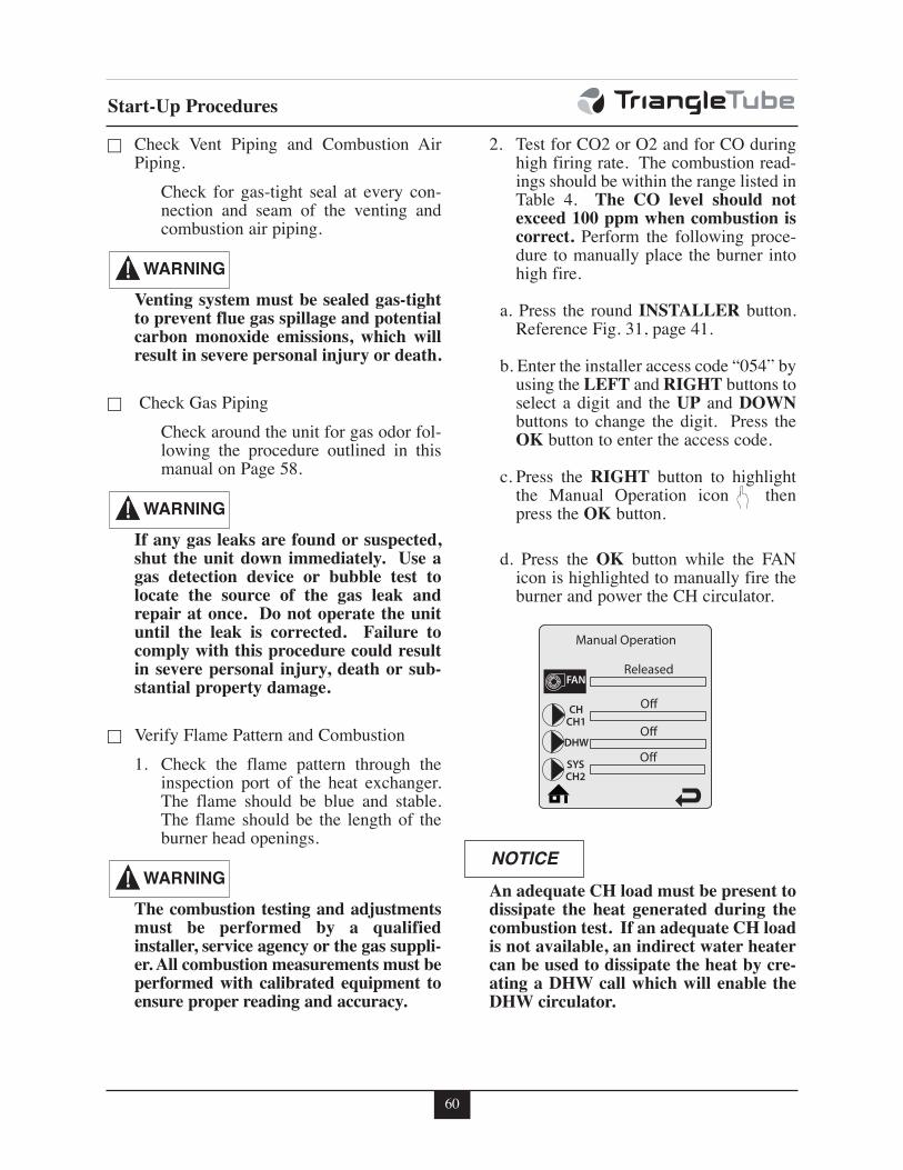
60
Start-Up Procedures
c Check Vent Piping and Combustion AirPiping.
Check for gas-tight seal at every con-nection and seam of the venting andcombustion air piping.
Venting system must be sealed gas-tightto prevent flue gas spillage and potentialcarbon monoxide emissions, which willresult in severe personal injury or death.
c Check Gas Piping
Check around the unit for gas odor fol-lowing the procedure outlined in thismanual on Page 58.
If any gas leaks are found or suspected,shut the unit down immediately. Use agas detection device or bubble test tolocate the source of the gas leak andrepair at once. Do not operate the unituntil the leak is corrected. Failure tocomply with this procedure could resultin severe personal injury, death or sub-stantial property damage.
c Verify Flame Pattern and Combustion
1. Check the flame pattern through theinspection port of the heat exchanger.The flame should be blue and stable.The flame should be the length of theburner head openings.
The combustion testing and adjustmentsmust be performed by a qualifiedinstaller, service agency or the gas suppli-er. All combustion measurements must beperformed with calibrated equipment toensure proper reading and accuracy.
2. Test for CO2 or O2 and for CO duringhigh firing rate. The combustion read-ings should be within the range listed inTable 4. The CO level should notexceed 100 ppm when combustion iscorrect. Perform the following proce-dure to manually place the burner intohigh fire.
a. Press the round INSTALLER button.Reference Fig. 31, page 41.
b. Enter the installer access code “054” byusing the LEFT and RIGHT buttons toselect a digit and the UP and DOWNbuttons to change the digit. Press theOK button to enter the access code.
c. Press the RIGHT button to highlightthe Manual Operation icon thenpress the OK button.
d. Press the OK button while the FANicon is highlighted to manually fire theburner and power the CH circulator.
An adequate CH load must be present todissipate the heat generated during thecombustion test. If an adequate CH loadis not available, an indirect water heatercan be used to dissipate the heat by cre-ating a DHW call which will enable theDHW circulator.
WARNING
WARNING
NOTICE
WARNING
Manual Operation
Released
O!
O!
O!
CHCH1
FAN
DHW
SYSCH2
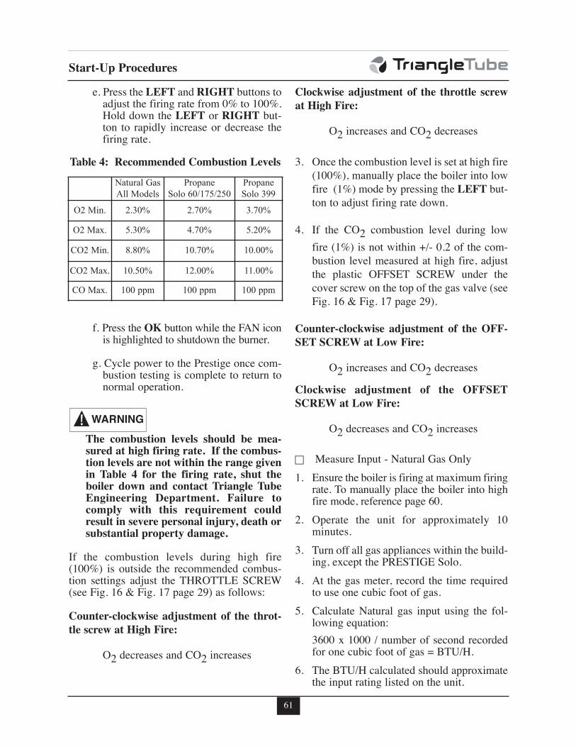
61
Start-Up Procedures
e. Press the LEFT and RIGHT buttons toadjust the firing rate from 0% to 100%.Hold down the LEFT or RIGHT but-ton to rapidly increase or decrease thefiring rate.
f. Press the OK button while the FAN iconis highlighted to shutdown the burner.
g. Cycle power to the Prestige once com-bustion testing is complete to return tonormal operation.
The combustion levels should be mea-sured at high firing rate. If the combus-tion levels are not within the range givenin Table 4 for the firing rate, shut theboiler down and contact Triangle TubeEngineering Department. Failure tocomply with this requirement couldresult in severe personal injury, death orsubstantial property damage.
If the combustion levels during high fire(100%) is outside the recommended combus-tion settings adjust the THROTTLE SCREW(see Fig. 16 & Fig. 17 page 29) as follows:
Counter-clockwise adjustment of the throt-
tle screw at High Fire:
O2 decreases and CO2 increases
Clockwise adjustment of the throttle screw
at High Fire:
O2 increases and CO2 decreases
3. Once the combustion level is set at high fire
(100%), manually place the boiler into low
fire (1%) mode by pressing the LEFT but-
ton to adjust firing rate down.
4. If the CO2 combustion level during low
fire (1%) is not within +/- 0.2 of the com-
bustion level measured at high fire, adjust
the plastic OFFSET SCREW under the
cover screw on the top of the gas valve (see
Fig. 16 & Fig. 17 page 29).
Counter-clockwise adjustment of the OFF-
SET SCREW at Low Fire:
O2 increases and CO2 decreases
Clockwise adjustment of the OFFSET
SCREW at Low Fire:
O2 decreases and CO2 increases
c Measure Input - Natural Gas Only
1. Ensure the boiler is firing at maximum firingrate. To manually place the boiler into highfire mode, reference page 60.
2. Operate the unit for approximately 10minutes.
3. Turn off all gas appliances within the build-ing, except the PRESTIGE Solo.
4. At the gas meter, record the time requiredto use one cubic foot of gas.
5. Calculate Natural gas input using the fol-lowing equation:
3600 x 1000 / number of second recordedfor one cubic foot of gas = BTU/H.
6. The BTU/H calculated should approximatethe input rating listed on the unit.
WARNING
Table 4: Recommended Combustion Levels
Natural Gas
All Models
Propane
Solo 60/175/250
Propane
Solo 399
O2 Min. 2.30% 2.70% 3.70%
O2 Max. 5.30% 4.70% 5.20%
CO2 Min. 8.80% 10.70% 10.00%
CO2 Max. 10.50% 12.00% 11.00%
CO Max. 100 ppm 100 ppm 100 ppm
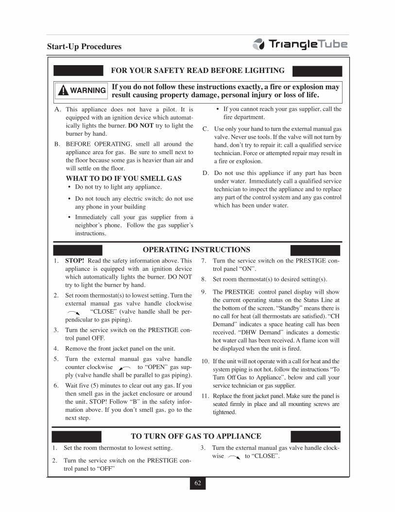
62
Start-Up Procedures
WARNING
FOR YOUR SAFETY READ BEFORE LIGHTING
OPERATING INSTRUCTIONS
TO TURN OFF GAS TO APPLIANCE
1. STOP! Read the safety information above. This
appliance is equipped with an ignition device
which automatically lights the burner. DO NOT
try to light the burner by hand.
2. Set room thermostat(s) to lowest setting. Turn the
external manual gas valve handle clockwise
“CLOSE” (valve handle shall be per-
pendicular to gas piping).
3. Turn the service switch on the PRESTIGE con-
trol panel OFF.
4. Remove the front jacket panel on the unit.
5. Turn the external manual gas valve handle
counter clockwise to “OPEN” gas sup-
ply (valve handle shall be parallel to gas piping).
6. Wait five (5) minutes to clear out any gas. If you
then smell gas in the jacket enclosure or around
the unit, STOP! Follow “B” in the safety infor-
mation above. If you don’t smell gas, go to the
next step.
7. Turn the service switch on the PRESTIGE con-
trol panel “ON”.
8. Set room thermostat(s) to desired setting(s).
9. The PRESTIGE control panel display will show
the current operating status on the Status Line at
the bottom of the screen. “Standby” means there is
no call for heat (all thermostats are satisfied). “CH
Demand” indicates a space heating call has been
received. “DHW Demand” indicates a domestic
hot water call has been received. A flame icon will
be displayed when the unit is fired.
10. If the unit will not operate with a call for heat and the
system piping is not hot, follow the instructions “To
Turn Off Gas to Appliance”, below and call your
service technician or gas supplier.
11. Replace the front jacket panel. Make sure the panel is
seated firmly in place and all mounting screws are
tightened.
If you do not follow these instructions exactly, a fire or explosion mayresult causing property damage, personal injury or loss of life.
1. Set the room thermostat to lowest setting.
2. Turn the service switch on the PRESTIGE con-
trol panel to “OFF”
3. Turn the external manual gas valve handle clock-
wise to “CLOSE”.
A. This appliance does not have a pilot. It is
equipped with an ignition device which automat-
ically lights the burner. DO NOT try to light the
burner by hand.
B. BEFORE OPERATING, smell all around the
appliance area for gas. Be sure to smell next to
the floor because some gas is heavier than air and
will settle on the floor.
WHAT TO DO IF YOU SMELL GAS• Do not try to light any appliance.
• Do not touch any electric switch; do not use
any phone in your building
• Immediately call your gas supplier from a
neighbor’s phone. Follow the gas supplier’s
instructions.
• If you cannot reach your gas supplier, call the
fire department.
C. Use only your hand to turn the external manual gas
valve. Never use tools. If the valve will not turn by
hand, don’t try to repair it; call a qualified service
technician. Force or attempted repair may result in
a fire or explosion.
D. Do not use this appliance if any part has been
under water. Immediately call a qualified service
technician to inspect the appliance and to replace
any part of the control system and any gas control
which has been under water.
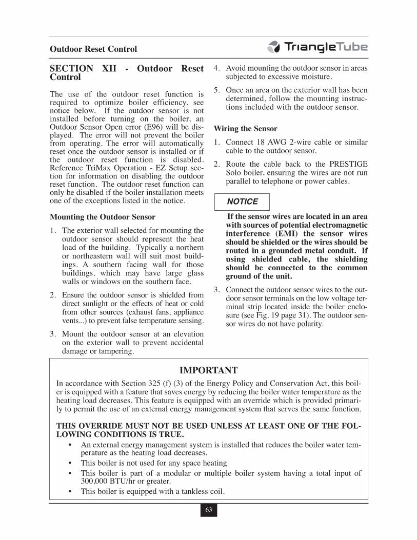
63
Outdoor Reset Control
SECTION XII - Outdoor ResetControl
The use of the outdoor reset function isrequired to optimize boiler efficiency, seenotice below. If the outdoor sensor is notinstalled before turning on the boiler, anOutdoor Sensor Open error (E96) will be dis-played. The error will not prevent the boilerfrom operating. The error will automaticallyreset once the outdoor sensor is installed or ifthe outdoor reset function is disabled.Reference TriMax Operation - EZ Setup sec-tion for information on disabling the outdoorreset function. The outdoor reset function canonly be disabled if the boiler installation meetsone of the exceptions listed in the notice.
Mounting the Outdoor Sensor
1. The exterior wall selected for mounting theoutdoor sensor should represent the heatload of the building. Typically a northernor northeastern wall will suit most build-ings. A southern facing wall for thosebuildings, which may have large glasswalls or windows on the southern face.
2. Ensure the outdoor sensor is shielded fromdirect sunlight or the effects of heat or coldfrom other sources (exhaust fans, appliancevents...) to prevent false temperature sensing.
3. Mount the outdoor sensor at an elevationon the exterior wall to prevent accidentaldamage or tampering.
4. Avoid mounting the outdoor sensor in areassubjected to excessive moisture.
5. Once an area on the exterior wall has beendetermined, follow the mounting instruc-tions included with the outdoor sensor.
Wiring the Sensor
1. Connect 18 AWG 2-wire cable or similarcable to the outdoor sensor.
2. Route the cable back to the PRESTIGESolo boiler, ensuring the wires are not runparallel to telephone or power cables.
If the sensor wires are located in an areawith sources of potential electromagneticinterference (EMI) the sensor wiresshould be shielded or the wires should berouted in a grounded metal conduit. Ifusing shielded cable, the shieldingshould be connected to the commonground of the unit.
3. Connect the outdoor sensor wires to the out-door sensor terminals on the low voltage ter-minal strip located inside the boiler enclo-sure (see Fig. 19 page 31). The outdoor sen-sor wires do not have polarity.
NOTICE
IMPORTANT
In accordance with Section 325 (f) (3) of the Energy Policy and Conservation Act, this boil-er is equipped with a feature that saves energy by reducing the boiler water temperature as theheating load decreases. This feature is equipped with an override which is provided primari-ly to permit the use of an external energy management system that serves the same function.
THIS OVERRIDE MUST NOT BE USED UNLESS AT LEAST ONE OF THE FOL-LOWING CONDITIONS IS TRUE.
• An external energy management system is installed that reduces the boiler water tem-perature as the heating load decreases.
• This boiler is not used for any space heating
• This boiler is part of a modular or multiple boiler system having a total input of300,000 BTU/hr or greater.
• This boiler is equipped with a tankless coil.
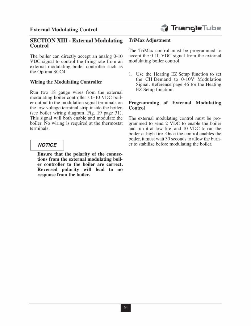
64
External Modulating Control
SECTION XIII - External ModulatingControl
The boiler can directly accept an analog 0-10VDC signal to control the firing rate from anexternal modulating boiler controller such asthe Optima SCC4.
Wiring the Modulating Controller
Run two 18 gauge wires from the externalmodulating boiler controller’s 0-10 VDC boil-er output to the modulation signal terminals onthe low voltage terminal strip inside the boiler.(see boiler wiring diagram, Fig. 19 page 31).This signal will both enable and modulate theboiler. No wiring is required at the thermostatterminals.
Ensure that the polarity of the connec-tions from the external modulating boil-er controller to the boiler are correct.Reversed polarity will lead to noresponse from the boiler.
TriMax Adjustment
The TriMax control must be programmed toaccept the 0-10 VDC signal from the externalmodulating boiler control.
1. Use the Heating EZ Setup function to setthe CH Demand to 0-10V ModulationSignal. Reference page 46 for the HeatingEZ Setup function.
Programming of External ModulatingControl
The external modulating control must be pro-grammed to send 2 VDC to enable the boilerand run it at low fire, and 10 VDC to run theboiler at high fire. Once the control enables theboiler, it must wait 30 seconds to allow the burn-er to stabilize before modulating the boiler.NOTICE
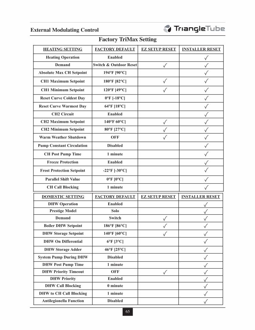
65
External Modulating Control
Factory TriMax Setting
HEATING SETTING FACTORY DEFAULT EZ SETUP RESET INSTALLER RESET
Heating Operation Enabled
Demand Switch & Outdoor Reset
Absolute Max CH Setpoint 194°F [90°C]
CH1 Maximum Setpoint 180°F [82°C]
CH1 Minimum Setpoint 120°F [49°C]
Reset Curve Coldest Day 0°F [-18°C]
Reset Curve Warmest Day 64°F [18°C]
CH2 Circuit Enabled
CH2 Maximum Setpoint 140°F 60°C]
CH2 Minimum Setpoint 80°F [27°C]
Warm Weather Shutdown OFF
Pump Constant Circulation Disabled
CH Post Pump Time 1 minute
Freeze Protection Enabled
Frost Protection Setpoint -22°F [-30°C]
Parallel Shift Value 0°F [0°C]
CH Call Blocking 1 minute
DOMESTIC SETTING FACTORY DEFAULT EZ SETUP RESET INSTALLER RESET
DHW Operation Enabled
Prestige Model Solo
Demand Switch
Boiler DHW Setpoint 186°F [86°C]
DHW Storage Setpoint 140°F [60°C]
DHW On Differential 6°F [3°C]
DHW Storage Adder 46°F [25°C]
System Pump During DHW Disabled
DHW Post Pump Time 1 minute
DHW Priority Timeout OFF
DHW Priority Enabled
DHW Call Blocking 0 minute
DHW to CH Call Blocking 1 minute
Antilegionella Function Disabled
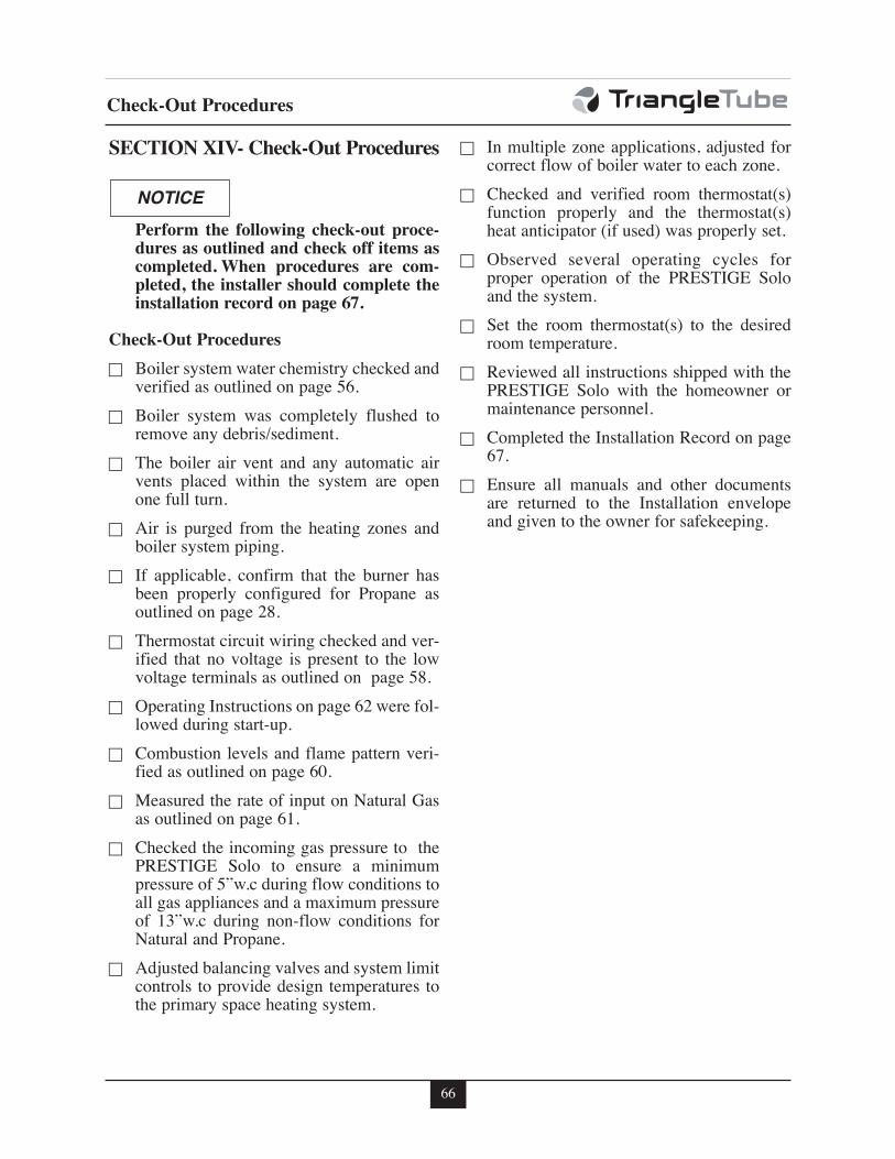
66
Check-Out Procedures
SECTION XIV- Check-Out Procedures
Perform the following check-out proce-dures as outlined and check off items ascompleted. When procedures are com-pleted, the installer should complete theinstallation record on page 67.
Check-Out Procedures
c Boiler system water chemistry checked andverified as outlined on page 56.
c Boiler system was completely flushed toremove any debris/sediment.
c The boiler air vent and any automatic airvents placed within the system are openone full turn.
c Air is purged from the heating zones andboiler system piping.
c If applicable, confirm that the burner hasbeen properly configured for Propane asoutlined on page 28.
c Thermostat circuit wiring checked and ver-ified that no voltage is present to the lowvoltage terminals as outlined on page 58.
c Operating Instructions on page 62 were fol-lowed during start-up.
c Combustion levels and flame pattern veri-fied as outlined on page 60.
c Measured the rate of input on Natural Gasas outlined on page 61.
c Checked the incoming gas pressure to thePRESTIGE Solo to ensure a minimumpressure of 5”w.c during flow conditions toall gas appliances and a maximum pressureof 13”w.c during non-flow conditions forNatural and Propane.
c Adjusted balancing valves and system limitcontrols to provide design temperatures tothe primary space heating system.
c In multiple zone applications, adjusted forcorrect flow of boiler water to each zone.
c Checked and verified room thermostat(s)function properly and the thermostat(s)heat anticipator (if used) was properly set.
c Observed several operating cycles forproper operation of the PRESTIGE Soloand the system.
c Set the room thermostat(s) to the desiredroom temperature.
c Reviewed all instructions shipped with thePRESTIGE Solo with the homeowner ormaintenance personnel.
c Completed the Installation Record on page67.
c Ensure all manuals and other documentsare returned to the Installation envelopeand given to the owner for safekeeping.
NOTICE
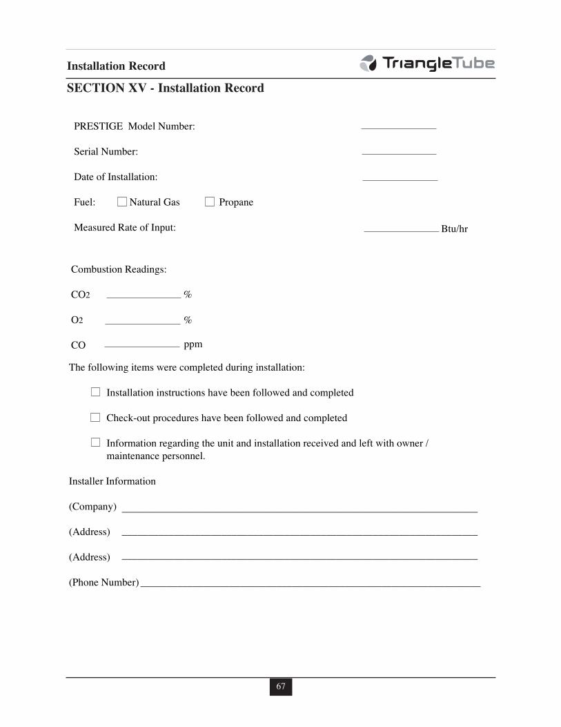
67
Installation Record
SECTION XV - Installation Record
PRESTIGE Model Number:
Serial Number:
Date of Installation:
Fuel: Natural Gas Propane
Measured Rate of Input:
Combustion Readings:
CO2
O2
CO
The following items were completed during installation:
Installation instructions have been followed and completed
Check-out procedures have been followed and completed
Information regarding the unit and installation received and left with owner / maintenance personnel.
Installer Information
(Company)
(Address)
(Address)
(Phone Number)
Btu/hr
____________________________________________________________________
____________________________________________________________________
____________________________________________________________________
_________________________________________________________________
%
%
ppm
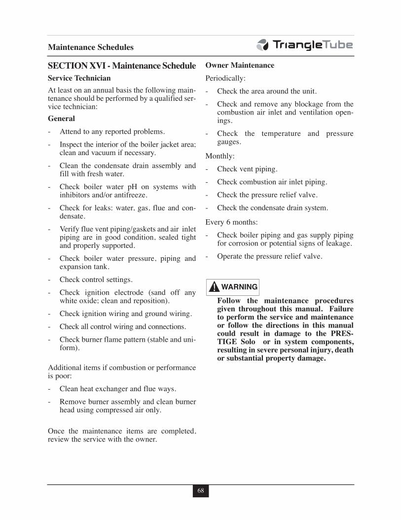
68
Maintenance Schedules
SECTION XVI - Maintenance Schedule
Service Technician
At least on an annual basis the following main-tenance should be performed by a qualified ser-vice technician:
General
- Attend to any reported problems.
- Inspect the interior of the boiler jacket area;clean and vacuum if necessary.
- Clean the condensate drain assembly andfill with fresh water.
- Check boiler water pH on systems withinhibitors and/or antifreeze.
- Check for leaks: water, gas, flue and con-densate.
- Verify flue vent piping/gaskets and air inletpiping are in good condition, sealed tightand properly supported.
- Check boiler water pressure, piping andexpansion tank.
- Check control settings.
- Check ignition electrode (sand off anywhite oxide; clean and reposition).
- Check ignition wiring and ground wiring.
- Check all control wiring and connections.
- Check burner flame pattern (stable and uni-form).
Additional items if combustion or performanceis poor:
- Clean heat exchanger and flue ways.
- Remove burner assembly and clean burnerhead using compressed air only.
Once the maintenance items are completed,review the service with the owner.
Owner Maintenance
Periodically:
- Check the area around the unit.
- Check and remove any blockage from thecombustion air inlet and ventilation open-ings.
- Check the temperature and pressuregauges.
Monthly:
- Check vent piping.
- Check combustion air inlet piping.
- Check the pressure relief valve.
- Check the condensate drain system.
Every 6 months:
- Check boiler piping and gas supply pipingfor corrosion or potential signs of leakage.
- Operate the pressure relief valve.
Follow the maintenance proceduresgiven throughout this manual. Failureto perform the service and maintenanceor follow the directions in this manualcould result in damage to the PRES-TIGE Solo or in system components,resulting in severe personal injury, deathor substantial property damage.
WARNING
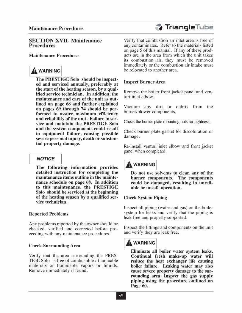
69
Maintenance Procedures
SECTION XVII- MaintenanceProcedures
Maintenance Procedures
The PRESTIGE Solo should be inspect-ed and serviced annually, preferably atthe start of the heating season, by a qual-ified service technician. In addition, themaintenance and care of the unit as out-lined on page 68 and further explainedon pages 69 through 74 should be per-formed to assure maximum efficiencyand reliability of the unit. Failure to ser-vice and maintain the PRESTIGE Soloand the system components could resultin equipment failure, causing possiblesevere personal injury, death or substan-tial property damage.
The following information providesdetailed instruction for completing themaintenance items outline in the mainte-nance schedule on page 68. In additionto this maintenance, the PRESTIGESolo should be serviced at the beginningof the heating season by a qualified ser-vice technician.
Reported Problems
Any problems reported by the owner should bechecked, verified and corrected before pro-ceeding with any maintenance procedures.
Check Surrounding Area
Verify that the area surrounding the PRES-TIGE Solo is free of combustible / flammablematerials or flammable vapors or liquids.Remove immediately if found.
Verify that combustion air inlet area is free ofany contaminates. Refer to the materials listedon page 5 of this manual. If any of these prod-ucts are in the area from which the unit takesits combustion air, they must be removedimmediately or the combustion air intake mustbe relocated to another area.
Inspect Burner Area
Remove the boiler front jacket panel and ven-turi inlet elbow.
Vacuum any dirt or debris from theburner/blower components.
Check the burner plate mounting nuts for tightness.
Check burner plate gasket for discoloration ordamage.
Re-install venturi inlet elbow and front jacketpanel when completed.
Do not use solvents to clean any of theburner components. The componentscould be damaged, resulting in unreli-able or unsafe operation.
Check System Piping
Inspect all piping (water and gas) on the boilersystem for leaks and verify that the piping isleak free and properly supported.
Inspect the fittings and components on the unitand verify they are leak free.
Eliminate all boiler water system leaks.Continual fresh make-up water willreduce the heat exchanger life causingboiler failure. Leaking water may alsocause severe property damage to the sur-rounding area. Inspect the gas supplypiping using the procedure outlined onPage 60.
NOTICE
WARNING
WARNING
WARNING
70
Maintenance Procedures
Clean Condensate Drain Assembly
1. Loosen the retaining nut from the conden-sate drain assembly and disconnect theassembly from the boiler.
2. Empty any water from the trap and drainassembly. Flush with fresh water as neces-sary to clean.
3. Check the drain piping from the condensatedrain assembly to the drain. Flush to cleanas necessary.
4. Reassemble the condensate drain assemblyonto the boiler by tightening the retainingnut with rubber seal onto the boiler. Handtight only.
5. Remove the fill plug on the condensate drainassembly and fill with water. See Fig. 14 onpage 25.
6. Replace the fill plug on drain assembly.
Check Ventilation Air Openings
Verify that all ventilation openings to themechanical room or building are open andunobstructed. Check the operation and wiringof any automatic ventilation dampers.
Check and verify the vent discharge and thecombustion air intake are free of debris andobstructions.
Inspect Vent and Combustion Air Piping
Visually inspect the venting system and com-bustion air piping for blockage, deteriorationof gaskets or leakage. Repair any deficiencies.
Verify that the combustion air inlet piping isconnected, sealed and properly supported.
Failure to inspect the vent system andcombustion air inlet piping and to haveany conditions repaired, can result insevere personal injury or death.
Check Boiler System
Verify all system components are correctlyinstalled and operating properly.
Check the cold fill pressure for the system, typ-ical cold water fill pressure is 12 psig.
Verify the system pressure, as the unit operates athigh temperature, to ensure the pressure does notexceed 25 psig. Excessive pressure reading indi-cates expansion tank sizing is incorrect or systemperformance problems.
Inspect air vent and air separators in the sys-tem. Remove the caps on automatic air ventsand briefly depress the valve stem to flushvent. Replace the cap when completed. Ensurevents do not leak, replace any leaking vents.
Verify boiler water pH level is between 6.0 and8.0.
Check and verify inhibitor /antifreeze concen-tration within the boiler water meetsinhibitor/antifreeze manuafacturer’s specifica-tions.
If necessary contact a boiler water treatmentcompany for a chemical analysis.
WARNING
71
Maintenance Procedures
Check Expansion Tank
Refer to Section IV - Boiler Piping for rec-ommended location of the expansion tankand air eliminators.
Closed -Type Tank:
- Ensure tank is partially filled withwater leaving an air gap as a cushion.Refer to the manufacturer’s instructionfor proper fill level.
- Ensure the tank is fitted with a devicethat reduces gravity circulation of air-saturated tank water back into the sys-tem. This device prevents air frombubbling up through the water as itreturns from the system.
- Ensure no automatic air vents are usedin the system. This will allow air toescape from the system instead ofreturning to the tank.
Diaphragm Tank:
- Ensure the system contains a minimum ofone automatic air vent. Recommendedlocation of the air vent should be atop anair eliminator.
- Remove the tank from the system andcheck the charge pressure. For residen-tial applications the charge pressure istypically 12 psig. If tank does not holda charge pressure, then the membrane isdamaged and the tank should bereplaced.
Check Boiler Relief Valve
Inspect the relief valve and lift the lever to ver-ify flow at least annually or as recommendedon the warning tag of the valve.
Before manually operating the pressurerelief valve, ensure the discharge piping isdirected to a suitable place of disposal toavoid a potential scald hazard. The dis-charge piping must be full size withoutrestriction and installed to permit com-plete drainage of both the valve and line.
If after closing the valve, the valve fails to seatproperly or continually weeps, replace therelief valve. Ensure the cause of the reliefvalve to weep is the valve itself, not due to sys-tem over-pressurization caused by an expan-sion tank that is waterlogged or undersized.
Inspection of Ignition Electrode
Remove the ignition electrode from the burnermounting plate.
Remove any white oxides accumulated on theelectrode using fine grit sandpaper or steel wool.If the electrode does not clean to a satisfactorycondition, replace the ignitor .
When replacing the ignition electrode, ensurethe gasket is in good condition and correctlypositioned, replace gasket if necessary.
Check Ignition Wiring and Ground Wiring
Inspect the ignition cable from the ignitor tothe TriMax control module.
Inspect the ground wire from the ignitor to theboiler jacket ground terminals.
Ensure wiring is in good condition and secure-ly connected.
Check ground continuity of the wiring to theboiler jacket or piping using a continuity meter.
Replace and correct ground wire if ground con-tinuity is not completed and satisfactory.
WARNING
72
Maintenance Procedures
Check Control Wiring
Inspect all control wiring. Ensure wiring is ingood condition and properly connected.
Check Control Settings
1. Review all boiler settings in the Heating &DHW EZ Setup menus. Adjust settings asnecessary, see page 46-49
2. Check any external limit control settings (ifused). Adjust settings as necessary.
Perform Start-up and Checkout Procedures
Start the unit and perform the start-up proce-dure as listed in this manual.
Verify the cold water fill pressure is correct andthe operating pressure of the boiler is withinnormal operating range.
Complete the checkout procedures as refer-enced in this manual.
Check Burner Flame
Inspect the burner flame through the observa-tion port on the heat exchanger.
If flame pattern is not fully blue and covers theentire burner surface during high fire, shut theunit down and allow it to cool thoroughly beforedisassembly.
Close the external manual gas valve on the gassupply line and disconnect the gas piping andgas valve wire harness connector.
Disconnect the wiring harness connectors fromthe blower and remove the blower retainingscrews or nuts. Remove the blower from theunit.
Remove the mounting nuts securing the burnermounting plate to the heat exchanger and setaside.
Carefully remove the burner mounting plateassembly from the heat exchanger. Ensurecombustion chamber insulation is not damagedduring removal of burner mounting plateassembly. See WARNING on page 74.
Remove the burner head mounting screws andremove the burner head. Inspect the burnerhead for deterioration. Use compressed air ora vacuum to clean the burner head.
Remove the venturi and gas valve assemblyfrom the blower.
Use a vacuum cleaner or compressed air toclean the interior of the blower assembly.Inspect the blower blades to ensure they areclean and not damaged.
Re-assemble the venturi and gas valve onto theblower. Ensure the venturi gasket is in goodcondition, positioned correctly and replace gas-ket if necessary.
Re-assemble the burner head onto the burnermounting plate. Ensure the burner head gasketis in good condition, positioned correctly andreplace gasket if necessary.
Re-assemble the burner mounting plate assem-bly onto the heat exchanger. Ensure the burnerplate gasket and combustion chamber insula-tion is in place and not damaged, replace gas-ket and insulation if necessary. See WARNINGon page 74.
Re-assemble the blower onto the burnermounting plate and reconnect the wiring har-ness connectors.
Re-assemble the gas supply connection andwire harness to gas valve. Open the externalmanual gas valve. Check gas piping for anyleaks as outlined on page 58 and repair if nec-essary. Place the unit back into service.
73
Maintenance Procedures
Check Flame Signal
The flame signal can be read from the BoilerInformation screen. It should be a min. 1μ Α−DC.
Check the ignitor for fouling or damagedinsulation if a low flame signal is read.
Check ground wiring and continuity as a causefor low flame signal. Replace ignitor if condi-tions are satisfactory.
Check Combustion Levels
Refer to page 60 of this manual for measuringcombustion levels and burner adjustments.
Check Flue Gas Temperature
1. Manually place the boiler into high fire.See page 60 for procedure.
2. Navigate to the Boiler Information Menuto observe the flue gas temperature. Seepage 50 for procedure.
3. If the flue gas temperature is more than 54°F[30°C] above the supply water temperature,shut the boiler down and follow the heatexchanger cleaning procedure below.
Clean Heat Exchanger
1. Shut down the boiler:
- Follow the instructions on Page 62 "ToTurn Off Gas to Appliance"
- Do not drain the boiler unless the boil-er will be subject to freezing condi-tions.
- Do not drain the boiler if freeze protec-tion fluid is used in the system.
2. Allow the boiler to cool down to room tem-perature before servicing.
3. Disconnect the gas piping and gas valvewire harness connector.
4. Disconnect the wiring harness connectorsfrom the blower and remove the blowerretaining screws or nuts. Remove the blow-er from the unit.
5. Remove the mounting nuts securing theburner mounting plate to the heat exchang-er and set aside.
6. Carefully remove the burner mountingplate assembly from the heat exchanger.Ensure combustion chamber insulation isnot damaged during removal of burnermounting plate assembly. See WARNINGon page 74.
7. Carefully remove the combustion chamberinsulation from the heat exchanger and setaside. See WARNING on page 74.
8. Use a vacuum cleaner, compressed air orwater to remove any accumulation fromthe heat exchanger flue ways. Do not useany solvent.
9. Re-install the combustion chamber insula-tion onto the heat exchanger.
10. Re-assemble the burner mounting plateassembly onto the heat exchanger. Ensurethe burner plate gasket and combustionchamber insulation is in place and not dam-aged, replace gasket and insulation if nec-essary. See WARNING on page 74.
11. Re-assemble the blower onto the burnermounting plate and reconnect the wiringharness connectors.
12. Reconnect the gas piping and wire harnessto gas valve. Check for leaks, repair if nec-essary.
13. Close isolation valves on the boiler waterpiping to isolate the boiler from the heatingsystem.
14. Attach a hose to the boiler drain valve andflush the boiler thoroughly with freshwater by using the purge valves to allowwater to enter through the make-up waterline to the boiler.
74
Maintenance Procedures
The combustion chamber insulationcontains ceramic fibers, which are clas-sified as a possible human carcinogen.When exposed to extremely high tem-peratures, the ceramic fibers, whichcontain crystalline silica, can be con-verted into cristobalite.
Avoid Breathing and Contact with Skinand Eyes
When removing or repairing the combustionchamber insulation follow these precautionmeasures:
1. Use a NIOSH approved respirator whichmeets OSHA requirements for cristobalitedust, similar to N95. Contact NIOSH at1-800-356-4676 or on the web atwww.cdc.gov/niosh for latest recommen-dations.
2. Wear long sleeved, loose fitting clothing,gloves and eyes protection.
3. Assure adequate ventilation.
4. Wash with soap and water after contact.
5. Wash potentially contaminated clothesseparately from other laundry and rinsewashing machine thoroughly.
6. Discard used insulation in an air tightplastic bag.
NIOSH Stated First Aid:Eye/Skin: Immediately irrigateBreathing: Clean fresh air
WARNING
Handling Previously Fired Combustion Chamber Insulation
15. Once the boiler has been completelyflushed, return the boiler and system pipingback to operation.
16. Perform the required startup and checkoutprocedures as outlined on pages 56 to 66.
Review With Owner
Ensure the owner understands the impor-tance to perform the maintenance schedulespecified in this manual.
Remind the owner of the importance to calla licensed contractor should the unit or sys-tem exhibit any unusual behavior.
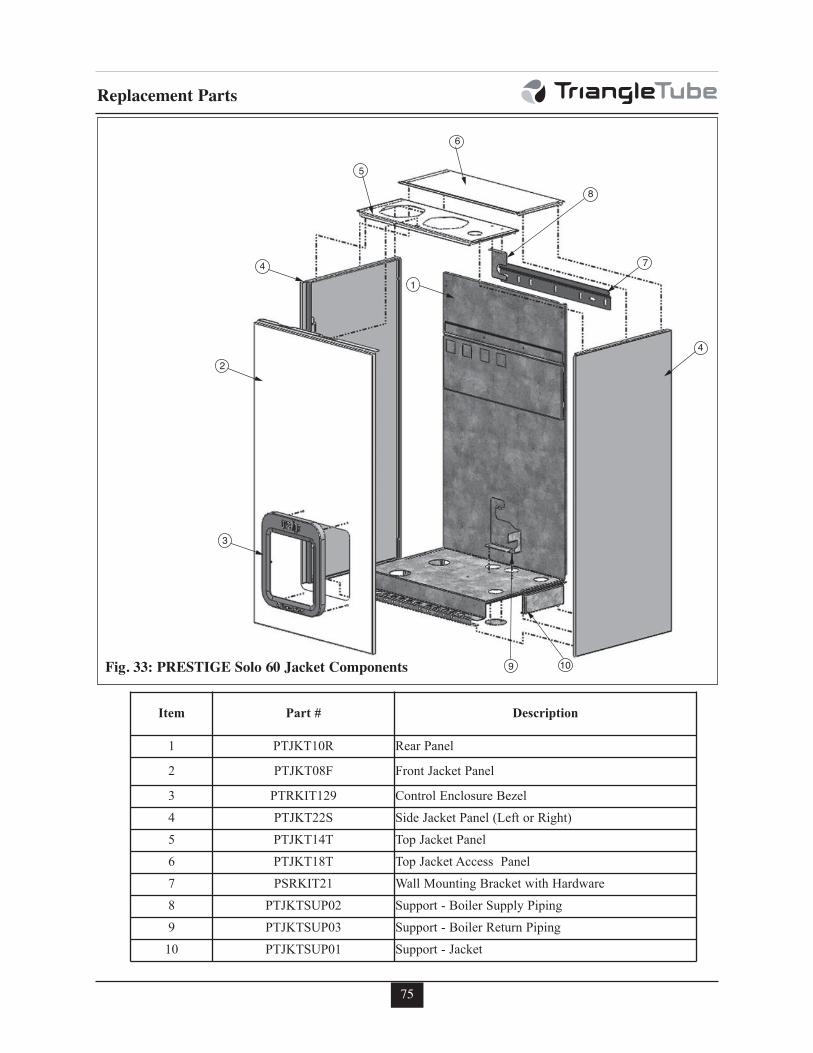
75
Replacement Parts
4
7
9 10
3
4
2
5
1
6
8
Fig. 33: PRESTIGE Solo 60 Jacket Components
Item Part # Description
1 PTJKT10R Rear Panel
2 PTJKT08F Front Jacket Panel
3 PTRKIT129 Control Enclosure Bezel
4 PTJKT22S Side Jacket Panel (Left or Right)
5 PTJKT14T Top Jacket Panel
6 PTJKT18T Top Jacket Access Panel
7 PSRKIT21 Wall Mounting Bracket with Hardware
8 PTJKTSUP02 Support - Boiler Supply Piping
9 PTJKTSUP03 Support - Boiler Return Piping
10 PTJKTSUP01 Support - Jacket
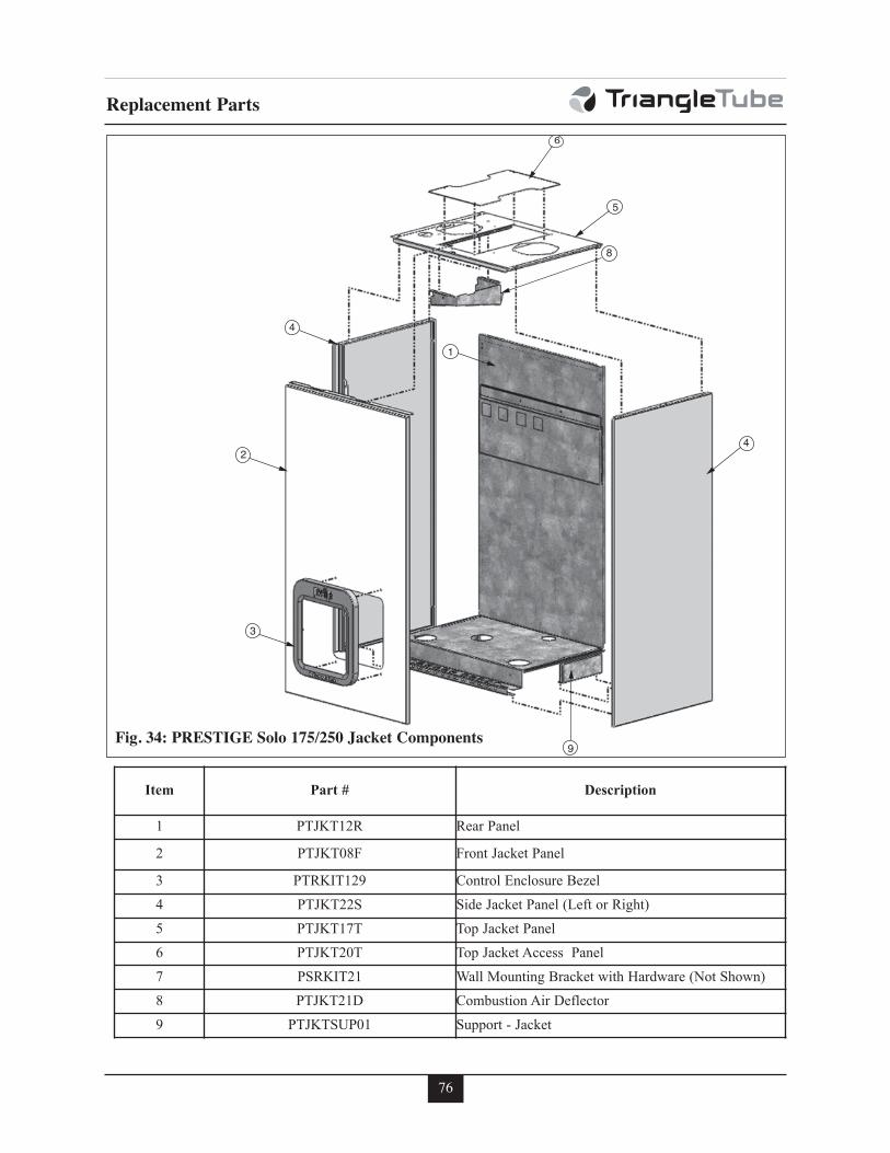
76
Replacement Parts
4
9
3
4
2
5
1
6
8
Fig. 34: PRESTIGE Solo 175/250 Jacket Components
Item Part # Description
1 PTJKT12R Rear Panel
2 PTJKT08F Front Jacket Panel
3 PTRKIT129 Control Enclosure Bezel
4 PTJKT22S Side Jacket Panel (Left or Right)
5 PTJKT17T Top Jacket Panel
6 PTJKT20T Top Jacket Access Panel
7 PSRKIT21 Wall Mounting Bracket with Hardware (Not Shown)
8 PTJKT21D Combustion Air Deflector
9 PTJKTSUP01 Support - Jacket
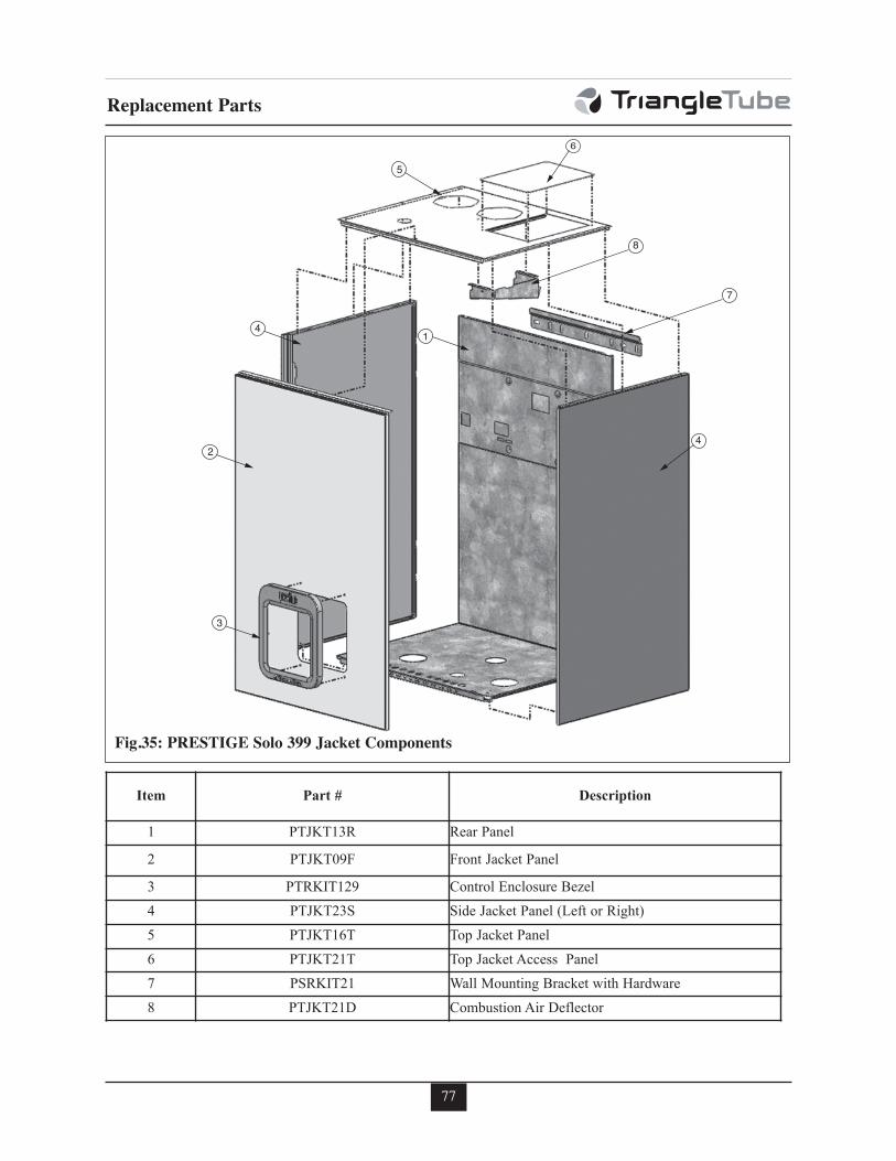
77
Replacement Parts
4
3
4
2
5
1
6
8
7
Fig.35: PRESTIGE Solo 399 Jacket Components
Item Part # Description
1 PTJKT13R Rear Panel
2 PTJKT09F Front Jacket Panel
3 PTRKIT129 Control Enclosure Bezel
4 PTJKT23S Side Jacket Panel (Left or Right)
5 PTJKT16T Top Jacket Panel
6 PTJKT21T Top Jacket Access Panel
7 PSRKIT21 Wall Mounting Bracket with Hardware
8 PTJKT21D Combustion Air Deflector
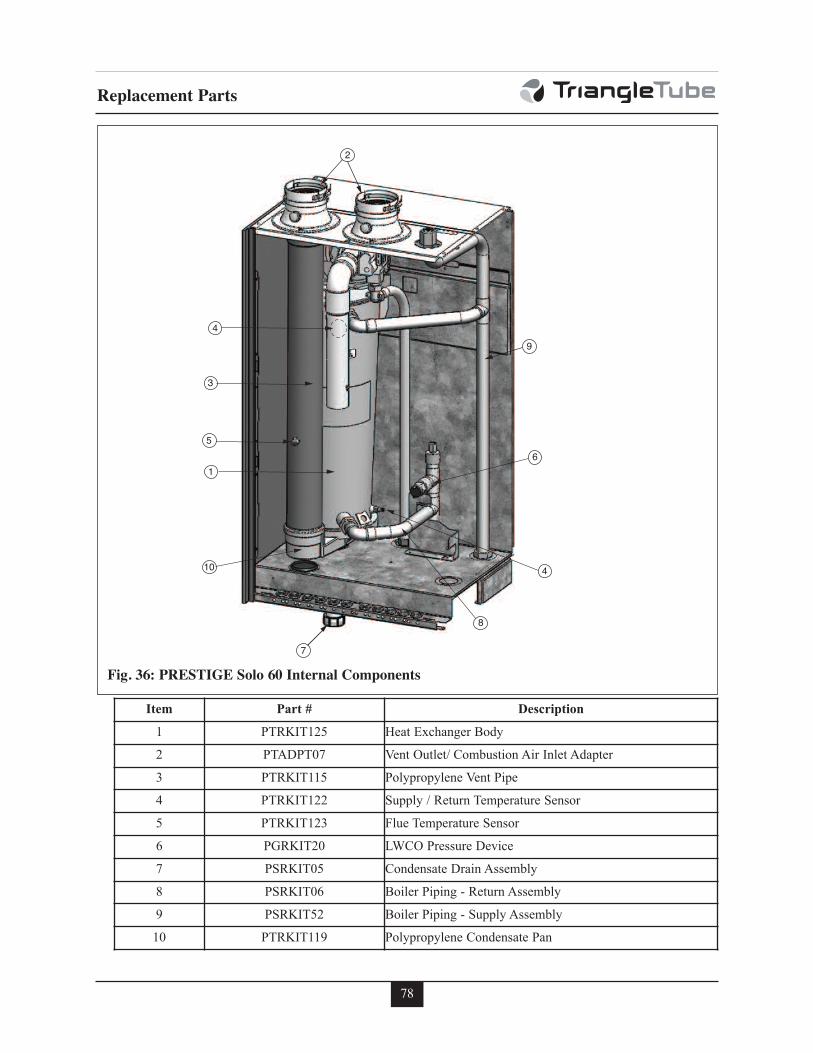
78
Replacement Parts
9
8
4
6
2
4
7
1
10
3
5
Fig. 36: PRESTIGE Solo 60 Internal Components
Item Part # Description
1 PTRKIT125 Heat Exchanger Body
2 PTADPT07 Vent Outlet/ Combustion Air Inlet Adapter
3 PTRKIT115 Polypropylene Vent Pipe
4 PTRKIT122 Supply / Return Temperature Sensor
5 PTRKIT123 Flue Temperature Sensor
6 PGRKIT20 LWCO Pressure Device
7 PSRKIT05 Condensate Drain Assembly
8 PSRKIT06 Boiler Piping - Return Assembly
9 PSRKIT52 Boiler Piping - Supply Assembly
10 PTRKIT119 Polypropylene Condensate Pan
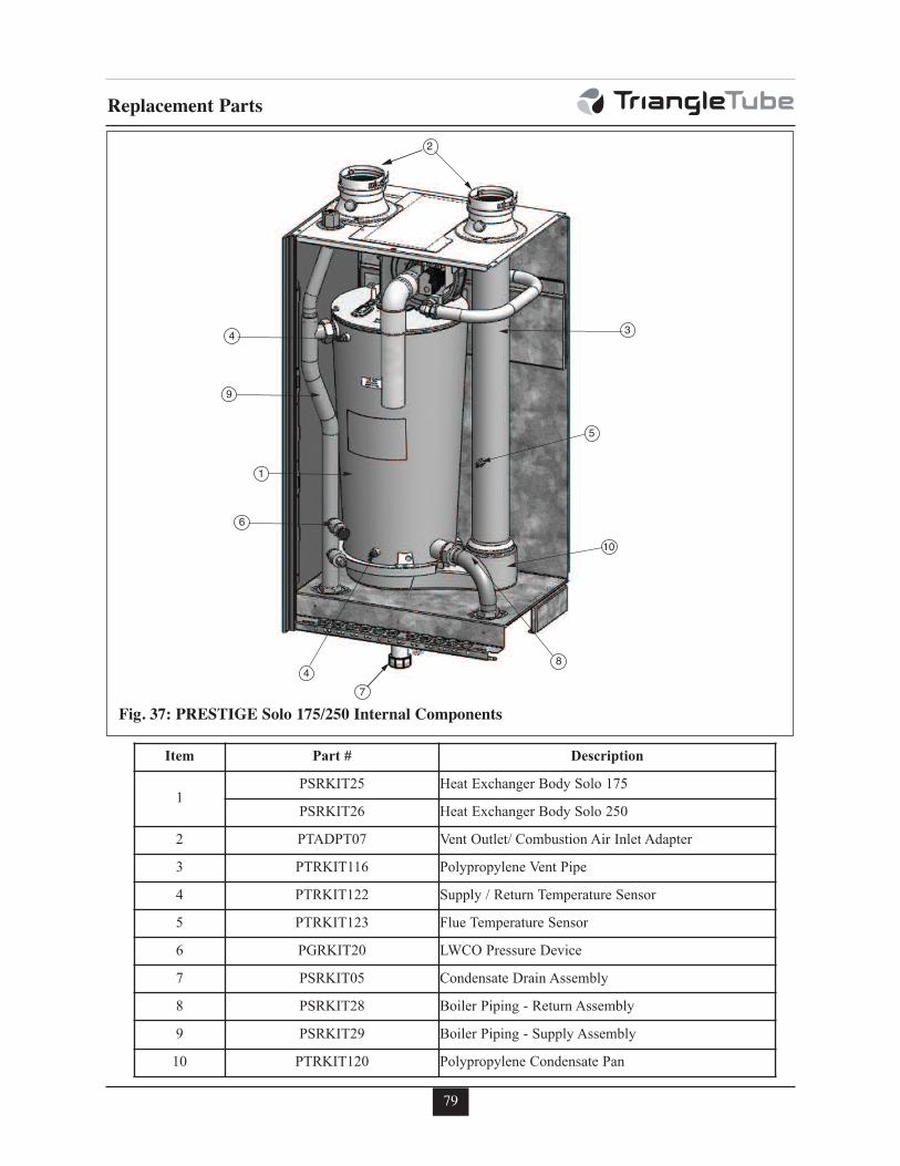
79
Replacement Parts
9
8
4
6
2
47
1
3
5
10
Fig. 37: PRESTIGE Solo 175/250 Internal Components
Item Part # Description
1PSRKIT25 Heat Exchanger Body Solo 175
PSRKIT26 Heat Exchanger Body Solo 250
2 PTADPT07 Vent Outlet/ Combustion Air Inlet Adapter
3 PTRKIT116 Polypropylene Vent Pipe
4 PTRKIT122 Supply / Return Temperature Sensor
5 PTRKIT123 Flue Temperature Sensor
6 PGRKIT20 LWCO Pressure Device
7 PSRKIT05 Condensate Drain Assembly
8 PSRKIT28 Boiler Piping - Return Assembly
9 PSRKIT29 Boiler Piping - Supply Assembly
10 PTRKIT120 Polypropylene Condensate Pan
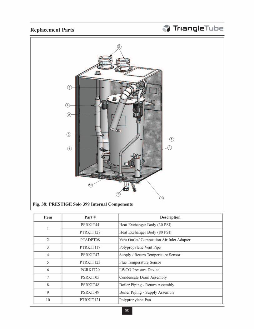
80
Replacement Parts
4
8
3
6
2
7
9
51
4
10
Fig. 38: PRESTIGE Solo 399 Internal Components
Item Part # Description
1PSRKIT44 Heat Exchanger Body (30 PSI)
PTRKIT128 Heat Exchanger Body (80 PSI)
2 PTADPT08 Vent Outlet/ Combustion Air Inlet Adapter
3 PTRKIT117 Polypropylene Vent Pipe
4 PSRKIT47 Supply / Return Temperature Sensor
5 PTRKIT123 Flue Temperature Sensor
6 PGRKIT20 LWCO Pressure Device
7 PSRKIT05 Condensate Drain Assembly
8 PSRKIT48 Boiler Piping - Return Assembly
9 PSRKIT49 Boiler Piping - Supply Assembly
10 PTRKIT121 Polypropylene Pan
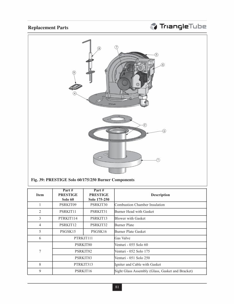
81
7
2
5
4
1
3
9
6
8
Fig. 39: PRESTIGE Solo 60/175/250 Burner Components
Replacement Parts
Item
Part #
PRESTIGE
Solo 60
Part #
PRESTIGE
Solo 175-250
Description
1 PSRKIT09 PSRKIT30 Combustion Chamber Insulation
2 PSRKIT11 PSRKIT31 Burner Head with Gasket
3 PTRKIT114 PSRKIT13 Blower with Gasket
4 PSRKIT12 PSRKIT32 Burner Plate
5 PSGSK15 PSGSK16 Burner Plate Gasket
6 PTRKIT111 Gas Valve
7
PSRKIT80 Venturi - 055 Solo 60
PSRKIT82 Venturi - 052 Solo 175
PSRKIT83 Venturi - 051 Solo 250
8 PTRKIT313 Igniter and Cable with Gasket
9 PSRKIT16 Sight Glass Assembly (Glass, Gasket and Bracket)
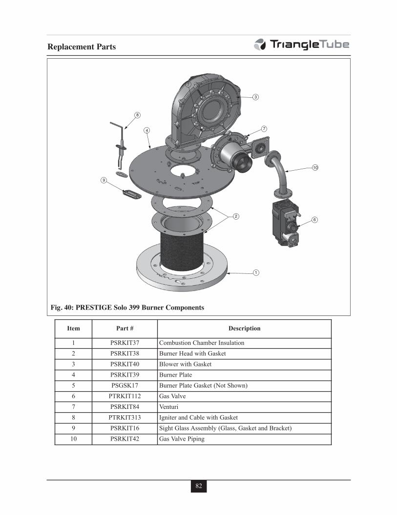
82
Replacement Parts
7
2
10
4
1
3
9
7
6
8
Fig. 40: PRESTIGE Solo 399 Burner Components
Item Part # Description
1 PSRKIT37 Combustion Chamber Insulation
2 PSRKIT38 Burner Head with Gasket
3 PSRKIT40 Blower with Gasket
4 PSRKIT39 Burner Plate
5 PSGSK17 Burner Plate Gasket (Not Shown)
6 PTRKIT112 Gas Valve
7 PSRKIT84 Venturi
8 PTRKIT313 Igniter and Cable with Gasket
9 PSRKIT16 Sight Glass Assembly (Glass, Gasket and Bracket)
10 PSRKIT42 Gas Valve Piping
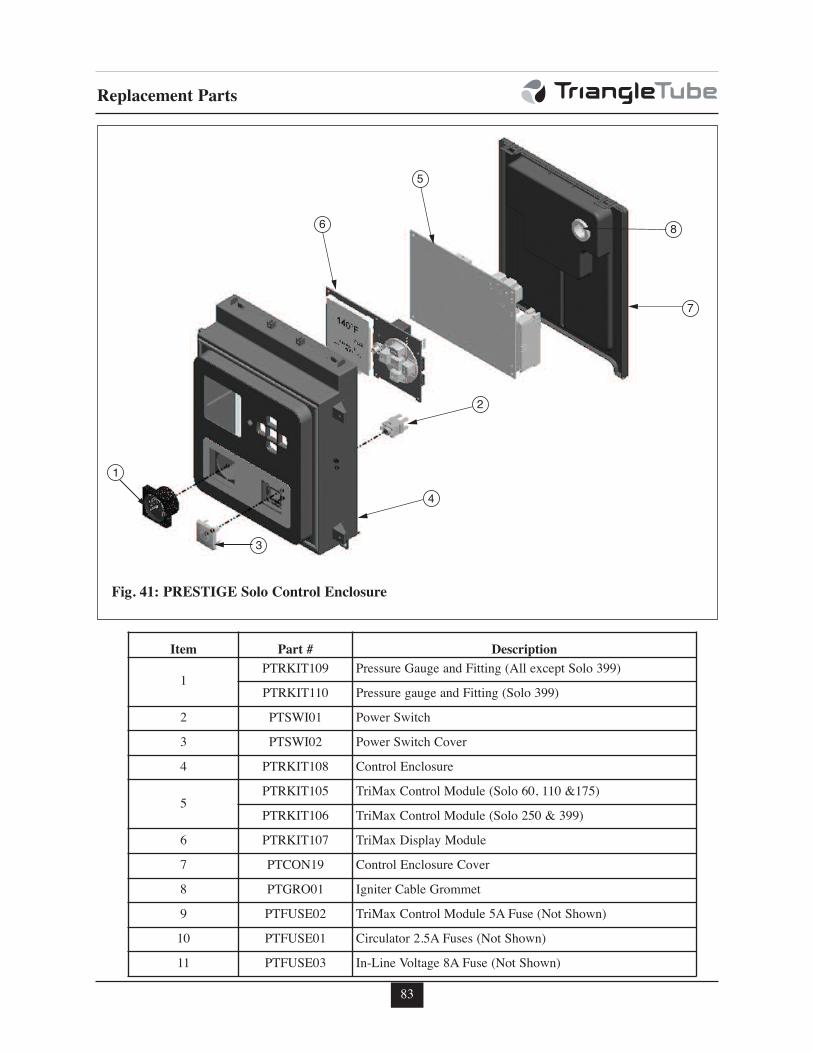
83
8
3
4
1
6
5
2
7
Fig. 41: PRESTIGE Solo Control Enclosure
Replacement Parts
Item Part # Description
1PTRKIT109 Pressure Gauge and Fitting (All except Solo 399)
PTRKIT110 Pressure gauge and Fitting (Solo 399)
2 PTSWI01 Power Switch
3 PTSWI02 Power Switch Cover
4 PTRKIT108 Control Enclosure
5PTRKIT105 TriMax Control Module (Solo 60, 110 &175)
PTRKIT106 TriMax Control Module (Solo 250 & 399)
6 PTRKIT107 TriMax Display Module
7 PTCON19 Control Enclosure Cover
8 PTGRO01 Igniter Cable Grommet
9 PTFUSE02 TriMax Control Module 5A Fuse (Not Shown)
10 PTFUSE01 Circulator 2.5A Fuses (Not Shown)
11 PTFUSE03 In-Line Voltage 8A Fuse (Not Shown)
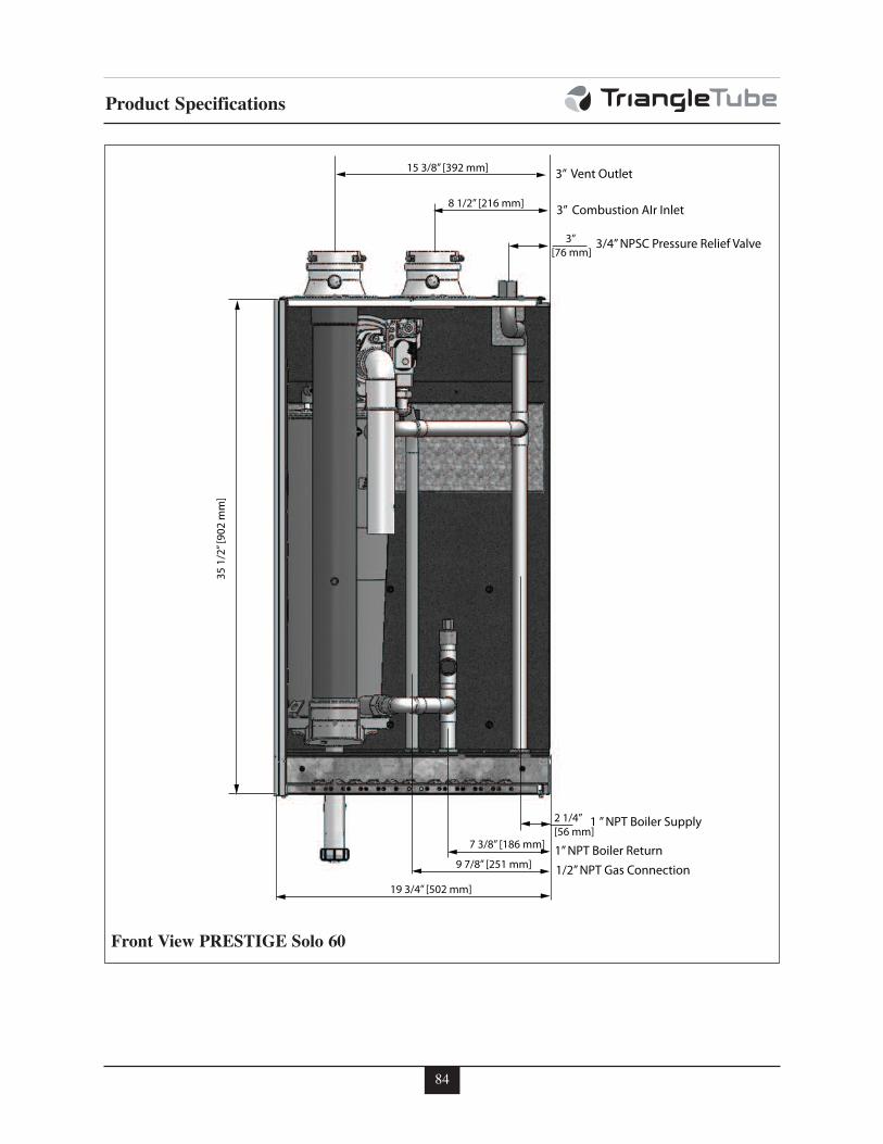
84
Product Specifications
35 1
/2” [
902
mm
]
15 3/8” [392 mm]
8 1/2” [216 mm]
9 7/8” [251 mm]
2 1/4” [56 mm]
3” [76 mm]
1 ” NPT Boiler Supply
1/2” NPT Gas Connection
3/4” NPSC Pressure Relief Valve
3” Combustion AIr Inlet
3” Vent Outlet
19 3/4” [502 mm]
7 3/8” [186 mm] 1” NPT Boiler Return
Front View PRESTIGE Solo 60
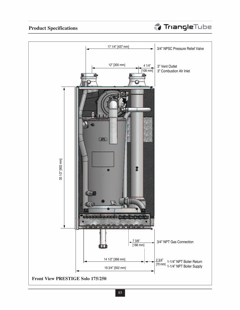
85
Product Specifications
35 1
/2” [
902
mm
]
17 1/4” [437 mm]
12” [305 mm] 4 1/4” [108 mm]
14 1/2” [368 mm] 2 3/4” [70 mm]
19 3/4” [502 mm]
7 3/8” [186 mm]
3/4” NPT Gas Connection
1-1/4” NPT Boiler Return1-1/4” NPT Boiler Supply
3” Vent Outlet3” Combustion AIr Inlet
3/4” NPSC Pressure Relief Valve
Front View PRESTIGE Solo 175/250
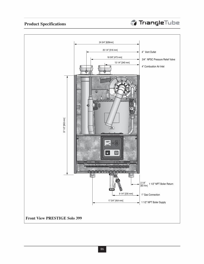
86
Product Specifications
37 1
/2” [
953
mm
]
24 3/4” [628mm]
20 1/4” [516 mm]
18 5/8” [473 mm]
13 1/4” [340 mm]
9 1/4” [235 mm]
3 1/4” [83 mm]
1 1/2” NPT Boiler Supply
1” Gas Connection
1 1/2” NPT Boiler Return
4” Combustion Air Inlet
3/4” NPSC Pressure Relief Valve
4” Vent Outlet
17 3/4” [454 mm]
Front View PRESTIGE Solo 399
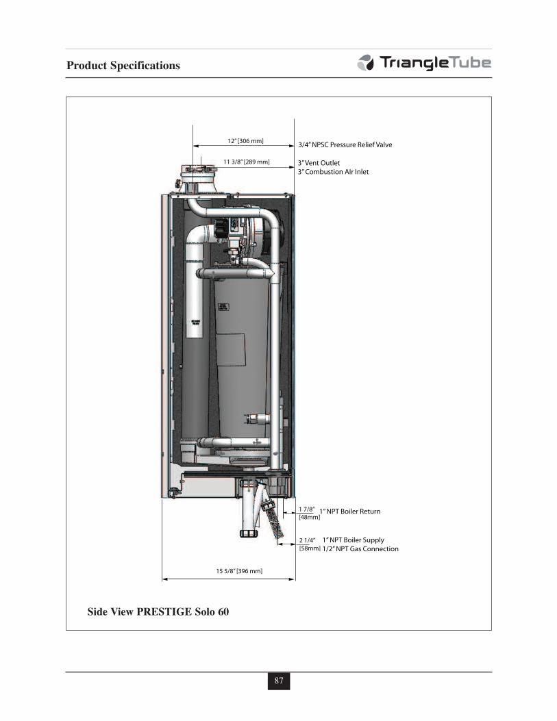
87
Product Specifications
11 3/8” [289 mm]
1 7/8” [48mm]
15 5/8” [396 mm]
2 1/4” [58mm]
12” [306 mm]
1” NPT Boiler Return
1” NPT Boiler Supply1/2” NPT Gas Connection
3” Vent Outlet3” Combustion AIr Inlet
3/4” NPSC Pressure Relief Valve
Side View PRESTIGE Solo 60
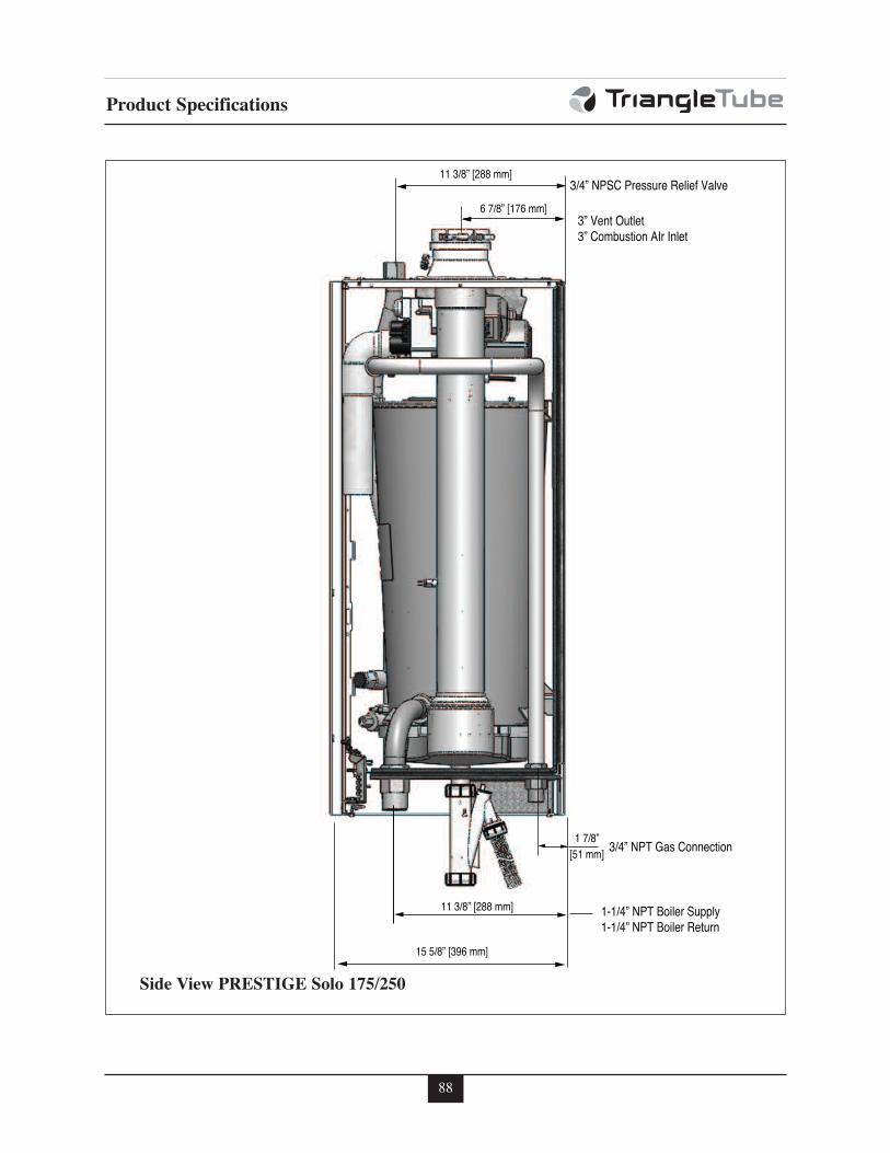
88
Product Specifications
11 3/8” [288 mm]
6 7/8” [176 mm]
11 3/8” [288 mm]
1 7/8” [51 mm]
15 5/8” [396 mm]
3/4” NPT Gas Connection
1-1/4” NPT Boiler Supply1-1/4” NPT Boiler Return
3” Vent Outlet3” Combustion AIr Inlet
3/4” NPSC Pressure Relief Valve
Side View PRESTIGE Solo 175/250
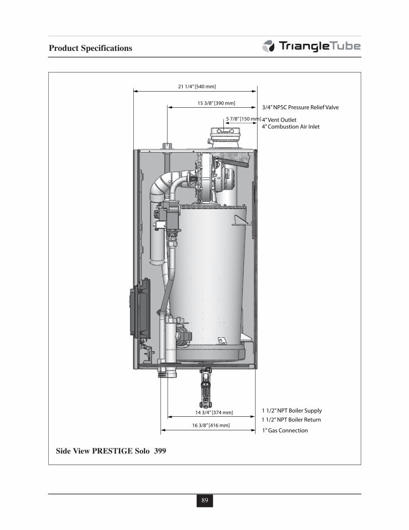
89
Product Specifications
21 1/4” [540 mm]
15 3/8” [390 mm]
14 3/4” [374 mm]
16 3/8” [416 mm]
5 7/8” [150 mm]
1 1/2” NPT Boiler Supply
1 1/2” NPT Boiler Return
1” Gas Connection
4” Combustion Air Inlet4” Vent Outlet
3/4” NPSC Pressure Relief Valve
Side View PRESTIGE Solo 399
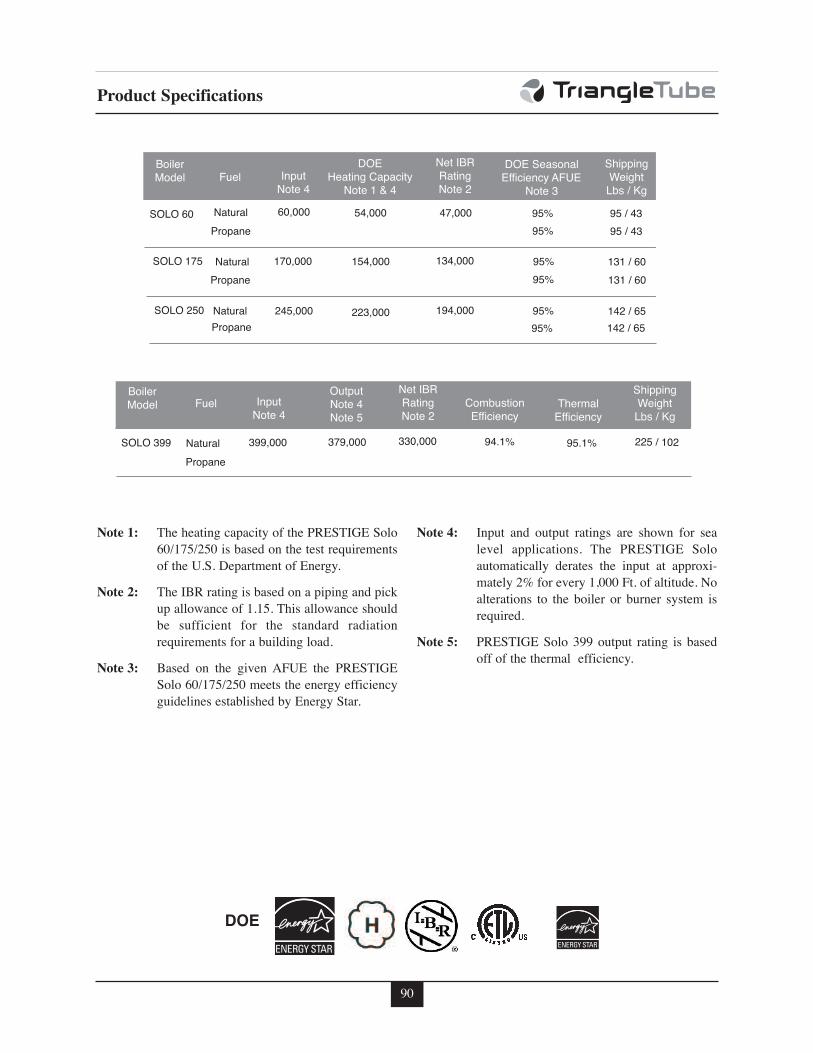
90
Product Specifications
Output Note 4
157,500
94.1%
95.1%
Fuel Combustion Efficiency
Input Note 4
Output Note 4 Note 5
Thermal Efficiency
Net IBR Rating Note 2
Shipping Weight
Lbs / Kg
Boiler Model
225,500
379,000 399,000 330,000 225 / 102 Natural SOLO 399 102,500 110,000 102,500 Propane 87,000
Fuel DOE
Heating Capacity Note 1 & 4
Input Note 4
DOE Seasonal Efficiency AFUE
Note 3
Net IBR Rating Note 2
60,000 95%
Shipping Weight
Lbs / Kg
95 / 43 Natural
Boiler Model
SOLO 60 47,000 110,000 102,500 95% 95 / 43 Propane 87,000
154,000
54,000
170,000 95% 131 / 60 Natural SOLO 175 134,000 102,500 102,500 95% 131 / 60 Propane
Propane
87,000
223,000 245,000 95% 142 / 65 Natural SOLO 250 194,000 102,500 110,000 102,500 95% 142 / 65 87,000
Note 1: The heating capacity of the PRESTIGE Solo
60/175/250 is based on the test requirements
of the U.S. Department of Energy.
Note 2: The IBR rating is based on a piping and pick
up allowance of 1.15. This allowance should
be sufficient for the standard radiation
requirements for a building load.
Note 3: Based on the given AFUE the PRESTIGE
Solo 60/175/250 meets the energy efficiency
guidelines established by Energy Star.
Note 4: Input and output ratings are shown for sea
level applications. The PRESTIGE Solo
automatically derates the input at approxi-
mately 2% for every 1,000 Ft. of altitude. No
alterations to the boiler or burner system is
required.
Note 5: PRESTIGE Solo 399 output rating is based
off of the thermal efficiency.
DOE
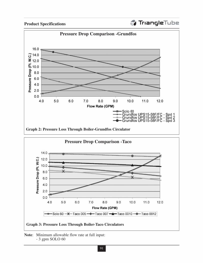
91
Product Specifications
Graph 2: Pressure Loss Through Boiler-Grundfos Circulator
Pressure Drop Comparison -Grundfos
Note: Minimum allowable flow rate at full input:- 3 gpm SOLO 60
Graph 3: Pressure Loss Through Boiler-Taco Circulators
Pressure Drop Comparison -Taco
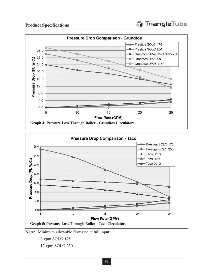
92
Product Specifications
Graph 4: Pressure Loss Through Boiler - Grundfos Circulators
Note: Minimum allowable flow rate at full input:
- 8 gpm SOLO 175
- 12 gpm SOLO 250
Graph 5: Pressure Loss Through Boiler - Taco Circulators
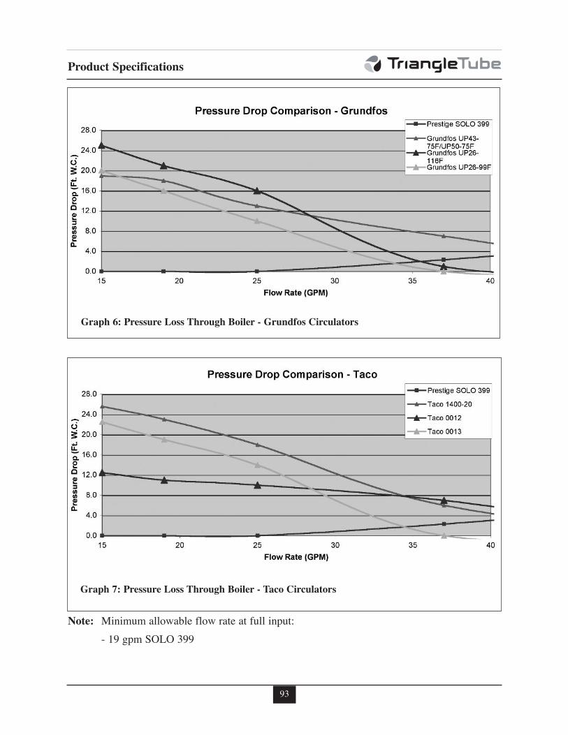
93
Product Specifications
Graph 6: Pressure Loss Through Boiler - Grundfos Circulators
Note: Minimum allowable flow rate at full input:
- 19 gpm SOLO 399
Graph 7: Pressure Loss Through Boiler - Taco Circulators

Additional quality water heating equipment available
from Triangle Tube
- Exclusive Tank-in-Tank design
- Stainless steel construction
- Available in 8 sizes and 2 models
- Limited LIFETIME residential warranty
- 15 year limited commercial warranty
- Self cleaning/self descaling design
TTP Brazed Plate Heat Exchangers
- For domestic water, snow melting, radiant floor,
refrigeration
- Plates made of stainless steel, with a 99.9 % copper
and brazed, ensuring a high resistance to corrosion
- Self cleaning and self descaling
- Computerized sizing available from Triangle
Tube/Phase III
- Available in capacities from 25,000 BTU/hr to
5,000,000 BTU/hr
SMART Indirect Fired Water Heaters
Freeway Center - 1 Triangle Lane - Blackwood, NJ 08012
Tel: (856) 228 8881 - Fax: (856) 228 3584
http://www.triangle tube.com - E-mail: Info@triangle tube.com
An
Company
Maxi-Flo and Spa Heat Exchangers
- Construction of high quality corrosion resistant
stainless steel (AISI 316) or titanium
- Specially designed built-in flow restrictor to assure
maximum heat exchange
- Compact and light weight
- Available in 5 sizes that can accommodate any size
pool or spa