Embed Size (px)
Citation preview
Pressurized
Water
Reactor

The core of a typical pressurized water reactor (PWR) contains about 100 tons of nuclear fuel.
The fuel consists of uranium dioxide pellets loaded in metal fuel rods placed in a square array called a fuel assembly. PWRs like Salem, South Texas Project, and Vogtle have 193 fuel assemblies in their cores.
PWRs operate for 18 to 24 months between refueling outages. During refueling, roughly one-third of the fuel assemblies are removed from the core to the spent fuel pool and replaced with fresh fuel assemblies.
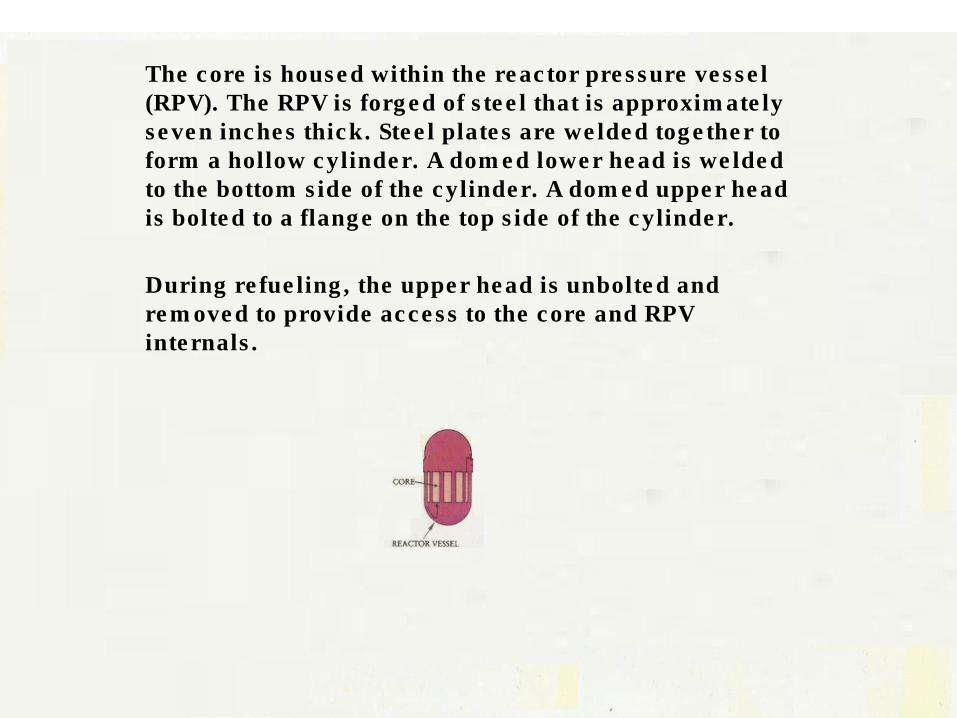
The core is housed within the reactor pressure vessel (RPV). The RPV is forged of steel that is approximately seven inches thick. Steel plates are welded together to form a hollow cylinder. A domed lower head is welded to the bottom side of the cylinder. A domed upper head is bolted to a flange on the top side of the cylinder.
During refueling, the upper head is unbolted and removed to provide access to the core and RPV internals.
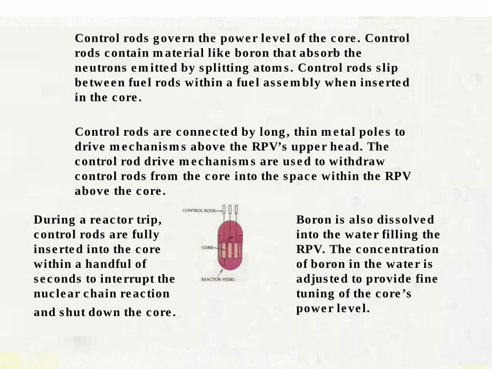
Control rods govern the power level of the core. Control rods contain material like boron that absorb the neutrons emitted by splitting atoms. Control rods slip between fuel rods within a fuel assembly when inserted in the core.
Control rods are connected by long, thin metal poles to drive mechanisms above the RPV’s upper head. The control rod drive mechanisms are used to withdraw control rods from the core into the space within the RPV above the core.
During a reactor trip, control rods are fully inserted into the core within a handful of seconds to interrupt the nuclear chain reaction
and shut down the core.
Boron is also dissolved into the water filling the RPV. The concentration of boron in the water is adjusted to provide fine tuning of the core’s power level.

Two to four loops connect to the RPV. Each loop consists of a steam generator, reactor coolant pump, and piping. The piping between the RPV and the steam generator is called the “hot leg.” The piping from the steam generator to the reactor coolant pump and back to the RPV is called the “cold leg.”
Water flowing up through the core is heated by the energy produced by splitting atoms. Because of high pressure, the water does not boil even though it is heated to 550 to 600ºF.
The hot water gives up some of this heat in the steam generator. The water temperature in the “cold leg” is only about 10ºF lower than the “hot leg” temperature.

Only one of the loops is equipped with a pressurizer. The pressurizer is a metal cylinder partially filled with water connected to the “hot leg.” The lower region of the pressurizer contains electric rings that are turned on to increase the temperature and pressure of the water flowing through the loops.
A piping run from the “cold leg” can be used to spray cooler water into the pressurizer to decrease the temperature and pressure of the water flowing through the loops.
In addition, the pressurizer accommodates expansion and shrinkage of water as it heats up and cools down during
plant operation.

The pressurizer is protected against bursting caused by over-pressurization. If the pressure rises too high, a relief valve automatically opens to vent fluid from the pressurizer to the pressurizer relief tank. Once the pressure drops sufficiently, the relief valve automatically closes.
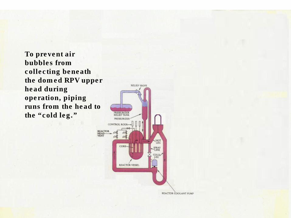
To prevent air bubbles from collecting beneath the domed RPV upper head during operation, piping runs from the head to the “cold leg.”
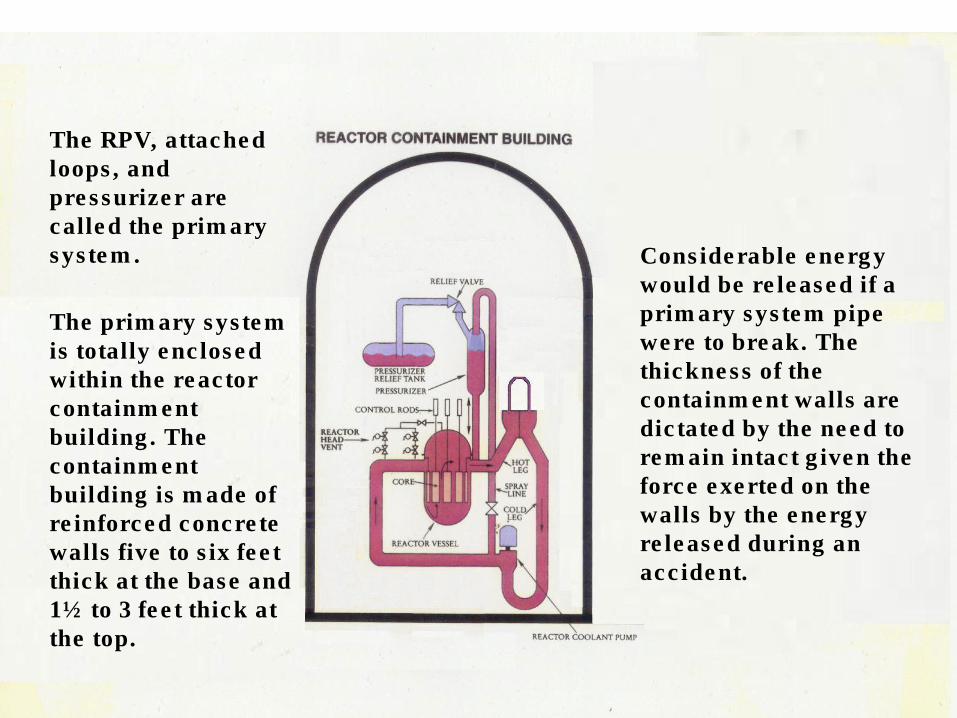
The RPV, attached loops, and pressurizer are called the primary system.
The primary system is totally enclosed within the reactor containment building. The containment building is made of reinforced concrete walls five to six feet thick at the base and 1½ to 3 feet thick at the top.
Considerable energy would be released if a primary system pipe were to break. The thickness of the containment walls are dictated by the need to remain intact given the force exerted on the walls by the energy released during an accident.

The condensate and main feedwater system is connected to the primary system loops at the steam generators.
The main feedwater pumps transfer water from the condenser hotwell to the steam generators.
The main feedwater pumps boost or back off their flow rates to maintain constant water levels in the steam generators.
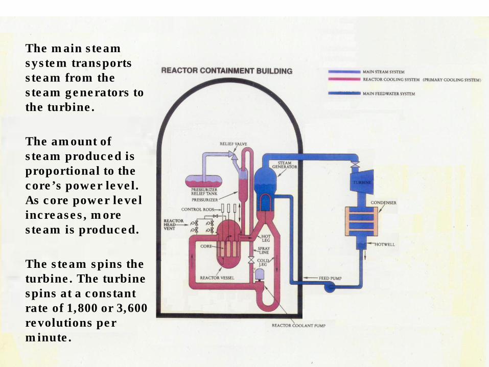
The main steam system transports steam from the steam generators to the turbine.
The amount of steam produced is proportional to the core’s power level. As core power level increases, more steam is produced.
The steam spins the turbine. The turbine spins at a constant rate of 1,800 or 3,600 revolutions per minute.
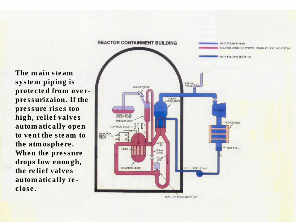
The main steam system piping is protected from over- pressurizaion. If the pressure rises too high, relief valves automatically open to vent the steam to the atmosphere. When the pressure drops low enough, the relief valves automatically re- close.

The turbine is connected to an electrical generator, the whole reason for the nuclear power plant.
The electricity from the main generator is routed through transformers to increase its voltage to that of the transmission grid.
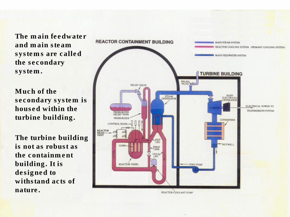
The main feedwater and main steam systems are called the secondary system.
Much of the secondary system is housed within the turbine building.
The turbine building is not as robust as the containment building. It is designed to withstand acts of nature.

Steam exits the turbine into the condenser, a large metal box. Water from the nearby lake, river, or ocean flows through thousands of metal tubes inside the condenser. The steam is cooled down and converted back into water dropping into the hotwell.
Water about 30ºF warmer is returned to the lake, river, or ocean.

The accumulators form part of the emergency core cooling systems (ECCS). The accumulators are metal cylinders partially filled with water and pressurized with nitrogen.
If the primary system pressure drops to less than half its normal operating pressure, indicative of a loss of water inventory, water from the accumulators automatically flows into the “cold leg.”

The charging pumps can transfer water from the refueling water storage tank to the “cold legs” to compensate for minor losses of water from the primary system.

During normal operation, primary system water flows continuously through the demineralizers and the volume control tank and then back to the “cold leg.”
This controls the water chemistry of the primary system.
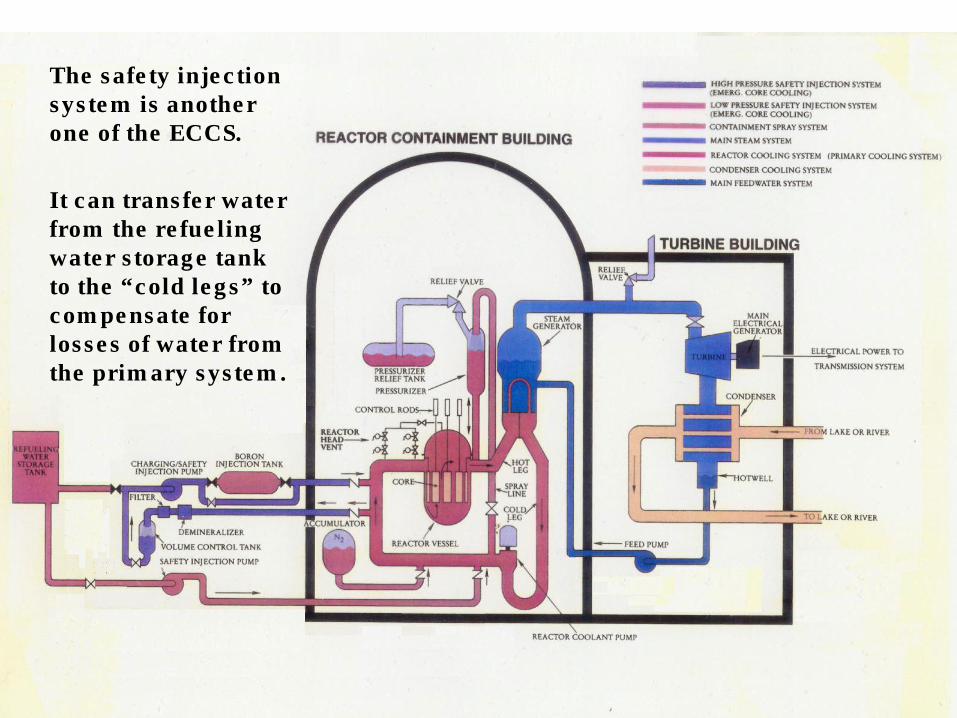
The safety injection system is another one of the ECCS.
It can transfer water from the refueling water storage tank to the “cold legs” to compensate for losses of water from the primary system.
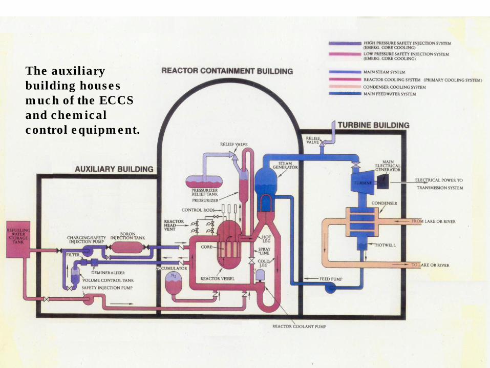
The auxiliary building houses much of the ECCS and chemical control equipment.

Because of equipment containing radioactive liquids and gases, the auxiliary building ventilation is filtered and monitored.
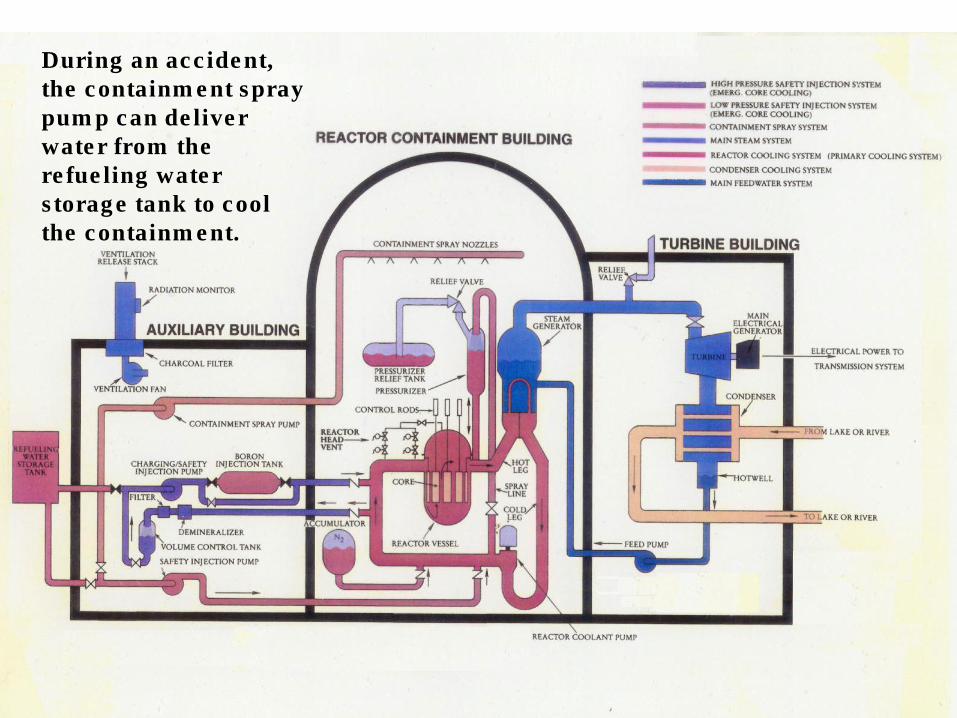
During an accident, the containment spray pump can deliver water from the refueling water storage tank to cool the containment.
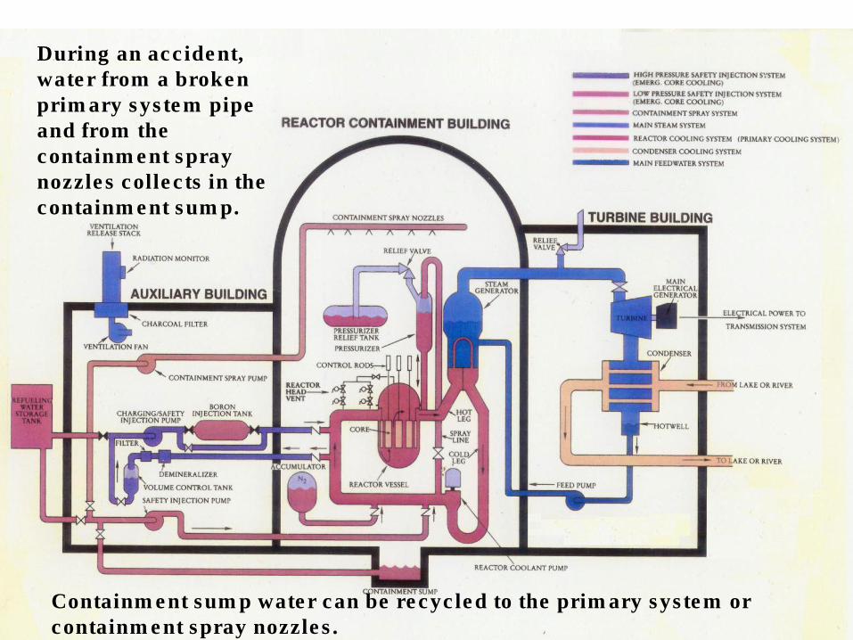
During an accident, water from a broken primary system pipe and from the containment spray nozzles collects in the containment sump.
Containment sump water can be recycled to the primary system or containment spray nozzles.
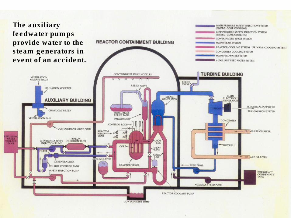
The auxiliary feedwater pumps provide water to the steam generators in event of an accident.
Pressuriz ed
Water
Reactor


![04158135 - Penn State Mechanical Engineering · 2012. 7. 5. · pressurized water reactor (PWR) [11], boiling water reactor (BWR) [12], and breeder reactor power plants [13]. The](https://img.pdfslide.us/doc/110x75/60faf1e4a0162e635f2d403a/04158135-penn-state-mechanical-2012-7-5-pressurized-water-reactor-pwr-11.jpg)


![Pressurized Water Reactor Steam Generator Lay-Up [Corrosion Evaluation]](https://img.pdfslide.us/doc/110x75/55cf9c70550346d033a9d943/pressurized-water-reactor-steam-generator-lay-up-corrosion-evaluation.jpg)