Embed Size (px)
Citation preview

www.walworth.com
PRESSURE SEAL
CATALOG

2 www.walworth.com
3www.walworth.com
INDEX INTRODUCTION
ENGINEERING CONTROL ............................................................................................................................................ 5QUALITY SYSTEM ........................................................................................................................................................ 5QUALITY CONTROL EQUIPMENT ............................................................................................................................... 9
GATE, GLOBE, GLOBE “Y” PATTERN, TILTING DISC CHECK, SWING DISC CHECK AND LIFT CHECK VALVES
PRESSURE SEAL BONNET VALVES BODY MATERIALS ........................................................................................11TRIM ARRANGEMENTS ............................................................................................................................................. 12 CONSTRUCTIONS MATERIAL COMBINATION ........................................................................................................ 13CHEMICAL COMPOSITION AND MECHANICAL PROPERTIES .............................................................................. 14CAST STEEL VALVES ................................................................................................................................................ 15GATE VALVES ............................................................................................................................................................. 16GATE VALVES CLASS 600 ......................................................................................................................................... 18GATE VALVES CLASS 900 ......................................................................................................................................... 20GATE VALVES CLASS 1500 ....................................................................................................................................... 22GATE VALVES CLASS 2500 ....................................................................................................................................... 24GLOBE VALVES .......................................................................................................................................................... 25GLOBE VALVES CLASS 600 ...................................................................................................................................... 27 GLOBE VALVES CLASS 900 ...................................................................................................................................... 29 GLOBE VALVES CLASS 1500 .................................................................................................................................... 31 GLOBE VALVES CLASS 2500 .................................................................................................................................... 33 GLOBE VALVES “Y” PATTERN ................................................................................................................................. 34 GLOBE VALVES “Y” PATTERN CLASS 600 ............................................................................................................. 36 GLOBE VALVES “Y” PATTERN CLASS 900 ............................................................................................................. 38 GLOBE VALVES “Y” PATTERN CLASS 1500 ........................................................................................................... 40 GLOBE VALVES “Y” PATTERN CLASS 2500 ........................................................................................................... 42 TILTING DISC CHECK VALVES .................................................................................................................................. 43 TILTING DISC CHECK VALVES CLASS 600 ............................................................................................................. 45 TILTING DISC CHECK VALVES CLASS 900 ............................................................................................................. 46 TILTING DISC CHECK VALVES CLASS1500 ............................................................................................................ 47 TILTING DISC CHECK VALVES CLASS 2500 ........................................................................................................... 48SWING DISC CHECK VALVES ................................................................................................................................... 49SWING DISC CHECK VALVES CLASS 600 ............................................................................................................... 51 SWING DISC CHECK VALVES CLASS 900 ............................................................................................................... 52 SWING DISC CHECK VALVES CLASS1500 .............................................................................................................. 53 SWING DISC CHECK VALVES CLASS 2500 ............................................................................................................. 54 LIFT CHECK VALVES ................................................................................................................................................. 55 LIFT CHECK VALVES CLASS 600 ............................................................................................................................. 57 LIFT CHECK VALVES CLASS 900 ............................................................................................................................. 58 LIFT CHECK VALVES CLASS1500 ............................................................................................................................ 59 LIFT CHECK VALVES CLASS 2500 ........................................................................................................................... 60TECHINICAL INFORMATION ...................................................................................................................................... 61 PRESSURE-TEMPRATURE RATINGS ....................................................................................................................... 65 DESIGN BASIS ............................................................................................................................................................ 70 HOW TO ORDER ......................................................................................................................................................... 71 GENERAL TERMS AND CONDITIONS ...................................................................................................................... 72

4 www.walworth.com
WALWORTH
WALWORTH is one of the world´s most comprehensive industrial valve manufacturers. Founded in 19th century by James Walworth, the Company has consistently dedicated itself to improvements in design and manufacturing of an array of valves exceptionally suited for the world´s fluid control sector. We satisfy all end use industries and comprehensive customer requirements by adhering to the most demanding quality standards.
WALWORTH relies on its broad experience in supplying valves to the petrochemical, oil & gas, petroleum, power generation, pulp and paper, cryogenic and geothermal industries, among others.
Over the years, Walworth has produced over 40,000 different types of products and serves as a global supplier to various markets utilizing the expertise of over 500 trained employees.
Our manufacturing system includes: utilization of Company directed raw material warehouses; modern and newly acquired specialized machinery; welding processes such as SMAW, GMAW, SAW, PAW; assembly testing for all low pressure, high pressure, and at low or high temperatures; painting and coating processes; export crating and shipment.
WALWORTH is capable of providing the world´s most comprehensive industrial valve line to the North American, Central American, South American, European and African markets. WALWORTH is proud to meet and satisfy the precise demands of our customers throughout the world by providing a quality product, competitive cost, and excellent service.
WALWORTH VALUESMISSIONWALWORTH manufactures and supplies world-class valves and components for the flow control industry through exceptional service, competitive pricing, and consistently, on-time deliveries.
VISIONTo be the world leader of unparalleled valve manufacturing and supply, WALWORTH:
• Set the standard for product quality in the flow control industry.
• Exceed the service expectations of our customers.• Forge enduring relationships with customers, team
members, and community.• Hire, develop, and retain experienced and dedicated
team members.

5www.walworth.com
WALWORTH ENGINEERING CONTROL
WALWORTH products are manufactured following strict international standards recognized all over the world, such as API, ANSI, ASME, ASTM, MSS, NACE, AWWA, BSI, and CSA, among others. Our Engineering team consistently monitors, updates and incorporates these standards and makes any applicable changes that affect the design, regulations, and/or performance of our products.
Our designs use the most advanced technology and equipment, finite elements, and CAD system programs to ensure proper assembly and performance. From conception to calculation to detailed drawings for manufacturers, WALWORTH is a leader in development of new products that meet the needs of the current valve market.
Throughout the years, WALWORTH has developed its Quality System which is an integral part of our manufacturing policy. Our primary goal is to provide products that meet and exceed market standards. In this sense, WALWORTH is an ISO-9001 Audited and Certified Company that has achieved major certifications worldwide. Our system includes the selection of raw materials from approved vendors, and rigorous oversight of our manufacturing process that is vital to quality control. The use of serial numbers allows WALWORTH the ability to not only ensure the quality of components used but to monitor and trace the fabrication process as well.
WALWORTH QUALITY SYSTEM
Certificate API-6D No. 6D-0097Issued by American Petroleum Institute to apply on Gate valves, Plug valves, Ball valves and Check valves manufactured in accordance with API-6D specification.
Certificate API-6A No. 6A-0234From American Petroleum Institute to apply on valves at PSI, 1 through 4.

6 www.walworth.com
Certificate API-594 No. 594-0007Issued by American PetroleumInstitute to apply on Check Valves-Type A; Check Valves Type B manufactured in accordance with API-594 specification.
API-600 Certificate No. 600-0109Issued by American Petroleum Institute to apply on Bolted Bonnet Steel Gate Valves manufactured in accordance with API-600 specification.
API-602 Certificate No. 602-0024Issued by American Petroleum Institute to apply on Compact Steel Gate Valves, Compact Steel Globe Valves, and Compact Steel Check Valves manufactured in accordance with API-602 specification.
Certificate as per PED 97/23/EC Module H To stamp CE products.
Certificate ISO-9001 No. 0038Issued by American Petroleum Institute since April 1999.

7www.walworth.com
Emissions after 500 cycles at ambient and 350 °FIssued by Yarmouth Research and Technology Lab for 3 inch Class 300 Gate Valve After 500 cycles the measurement result was less than 50 ppm.
Emissions after 500 cycles at ambient and 350 °FIssued by Yarmouth Research and Technology Lab for 8 inch Class 300 Gate Valve After 500 cycles the measurement result was less than 50 ppm.
Emissions after 500 cycles at ambient and 350 °FIssued by Yarmouth Research and Technology Lab for 16 inch Class 150 Gate Valve After 500 cycles the measurement result was less than 50 ppm.
Certificate NMX-CC-9001 (Mexican Standards ISO-9001) No. 0552/2007 Issued by PEMEX in accordance with ISO-9001 Quality Assurance System.
Supplier Qualification Certificate NO. 279/13 Issued by the Equipment and Materials Testing Laboratory, CFE (LAPEM in Spanish)
PRODUCT CERTIFICATIONS

8 www.walworth.com
TÜV Rheinland Certificate No. TRASA 700-13-0019API-6D Trunnion mounted bolted body ball valves, carbon steel (A105-WCB) construction, double block and bleed service, primarily used but not limited to the oil and gas standard and severe applications.
Certificates of Ultra Low Fugitive Emissions No. 20985-3, 8 & 16 in accordance with ISO-15848-1 “Industrial Valves”Measurement, Test and Qualification Procedures for Fugitive Emissions “Part 1: Classification System and Qualification Procedures for Type Testing of Valves”.
Fire Test Certificate No. 01-1/05In accordance with API-6FA and API Standard API-607 for Trunnion Ball Valves in accordance with API-6D.
TA Luft Certificate (Fugitive Emission) ApprovalISO-5211 Top Flange, Anti-Static Device.

9www.walworth.com
QUALITY CONTROL EQUIPMENT In order to assure that WALWORTH products comply with international quality standards, in-house equipment is kept for monitoring control, some of this equipment includes:
X-Ray Examination Equipment. WALWORTH has its own Ir-92 source in-house for the radiographic examination (RT) of castings from 0.100” up to 2 1/2” wall thickness to verify the soundness of the casting raw material.
Magnetic Particle Test. On a random basis for standard products or when a Customer requests MT Certification, WALWORTH has Magnetic Particle Test Equipment to perform on ferromagnetic materials.
Test Loop. A complete Laboratory Test loop exists for design validation of WALWORTH products. The test is performed at maximum design pressure, advances the valves from 3000 to 5000 cycles, and requires more than four months to complete.
PMI Equipment. A new generation of Positive Material Identification Equipment gives WALWORTH the capability to perform quick chemical analysis on incoming raw materials and on pieces after assembly, to certify that materials used were produced and assembled in accordance with WALWORTH’s and our Customer’s specifications.
Penetrant Test Examination. WALWORTH has the personnel and materials to perform PT examination by solvent removable or water washable techniques. NDT personnel are ASNT Certified.
Pressure Gradient Test Loop. This test exposes Plug valves to the extremes of both positive and negative pressure gradients to verify that the plug in a balanced plug design will prevent lock-up in the body.

10 www.walworth.com
Metrology Laboratory. WALWORTH developed a calibration and/or verification system in all of the equipment used in its facilities. This ensures our ability to trace measurements, control products, and comply with international standards.
Low Fugitive Emissions Test. This test is performed when a Customer requires low fugitive emissions certification. Our Lab has its own LFE test equipment that is capable of measuring less than 20 ppm in both static and mechanical conditions at either ambient temperature or thermal cycle operations.
Tensile Test Equipment. We use this equipment to verify the mechanical properties of materials used for manufacturing. WALWORTH tests samples on a random basis even thought we receive MTR’s from our suppliers and foundries.
Fire Test Facilities. WALWORTH has the facilities to perform fire tests in accordance with API requirements. The test exposes the valve to a fire flame at 1400 to 1800 °F (761 to 980 °C) to verify proper seal of the valve.
Ultrasonic Testing Equipment. Using ultrasonic techniques, we can detect sub surface flaws in materials and evaluate castings and forgings that cannot be radiographed. In addition, we utilize these techniques to measure the wall thickness of castings and forgings.
Hardness Test Equipments.- In both lab and shop tests, WALWORTH uses hardness tester equipment, such as Rockwell B, C Brinell or Vickers, to ensure compliance with specifications.

11www.walworth.com
PRESSURE CAST STEEL VALVES BODY MATERIALSMaterial suffix Common
designationForging
specificationWrought bar specifiction Service recommendations (1)
Common trim forthis base material
600 To 2500 #
ASTM A216 Grade WCB Carbon Steel A105 A105Non-corrosive applications including water, oil and gases at temperatures between -20°F (-30°F )and +800°F (+425°C)
HF, 3HF+HF, NUC
ASTM A216 Grade WCC Carbon Steel A105N A105NNon-corrosive applications including water, oil and gases at temperatures between -20°F (-30°F )and +800°F (+425°C)
HF, 3HF+HF, NUC
ASTM A217 Grade WC6 1 1/4% Chrome; 1/2% Moly Low Alloy Steel A182 F11 A182 F11
Class 2
Non-corrosive applications including water, oil and gases at temperatures between -20°F (-30°C) and + 1100°F(+593°C).
UT, 3HF, A
ASTM A217 Grade WC9 2 1/4 % Chrome Low Alloy Steel A182 F22 A182 F11
Class 3
Non-corrosive applications including water, oil and gases at temperatures between -20°F (-30°C) and + 1100°F(+593°C).
UT, 3HF, A
ASTM A217 Grade C5 5% Chrome; 1/2 % Moly, Medium Alloy Steel A182 F5 A182 F5
Mild corrosive or erosive applications as well as non-corrosive applications at temperatures between- 20°F (-3O°C) and + 1200°F (+649°C).
UT, 3HF, A
ASTM A217 Grade C12 9% Chrome; 1% Moly, Medium Alloy Steel A182 F9 A182 F9
Mild corrosive or erosive applications as well as non-corrosive applications at temperatures between- 20°F (-3O°C) and + 1200°F (+649°C).
UT, 3HF, A
ASTM A217 Grade C12-A 9% Chrome; 1% Moly; V-N, Medium Alloy Steel A182 F91 A182 F91
Mild corrosive or erosive applications as well as non-corrosive applications at temperatures between- 20°F (-3O°C) and + 1200°F (+649°C).
HF, 3HF+HF, NUC
ASTM A351 Grade CF8 18% Chrome; 8% Nickel; 0.08 % C Stainless Steel
ASTM A182 F304
ASTM A479 304
Corrosive or extremely high temperature non-corrosive serviceS between -450°F (- 268°C) and + 1200°F (+649°C). Above + 800°F ( + 425°C) specify carbon content of 0.04% or greater.
4HF+HF
ASTM A351 Grade CF8M18% Chrome; 12% Nickel; 2 % Mo; 0.08 % C Stainless Steel
ASTM A182 F316
ASTM A479 316
Corrosive or either extremely low or high temperature non-corrosive services between -450°F (-268°C) and + 1200°F (+ 649°C). Above +800°F (+ 425°C)specify carbon content of 0.04% or greater.
3HF+HF
ASTM A351 Grade CF8C18% Chrome; 10% Nickel; Cb; 0.08 % C Stainless Steel
ASTM A182 F347
ASTM A479 347
Primarily for high temperature, corrosive applications between -450°F (-268°C) and + 1200°F (+ 649°C). Above +1000°F (+540°C) specify carbon oontent of 0.04% or greater. Hydrogen service.”
347HF
ASTM A487 Grade CA15 12% Chrome Steel ASTM A182 F6
ASTM A276 410
Corrosive application at temperatures between -20°F (-30°C) and + 900°F (+482°C). HF, NUC
ASTM A487 Grade CA6NM 12% Chrome Steel ASTM A182 F6
ASTM A276 410
Corrosive application at temperatures up to +1300°F (704°C). Boiler feed water 250 °F (115°C), sea water, steam sulfur.
HF, NUC
ASTM A494 Grade M-35-1 67% Ni; 30% Cu, Monel ASTM B564 N04400
ASTM B164 N04400
Weldable grade. Good resistance to corrosion by all common organic acids and salt water. Also highly resistant to most alkaline solutions to +7W°F (+400°C)
AHF
ASTM A494 Grade CY-40 75% Nickel; 15% Cr; 8% Fe, Inconel 600
ASTM B564 N06600
ASTM B166 N06600
Very good for high temperature senvice. Good resistance to strongly corrosive media and atmosphere to + 800°F (+425°C). Hot boiler feed water, hot caustics, hot concentrate alk water, elevated temperature oxidizing conditions.
600HF
ASTM A494 Grade CW6MC60% Nickel; 22% Cr; 9% Mo; 3.5% Cb, Inconel 625
ASTM B564 N06625
ASTM B446 N06625
Very good for high temperature senvice. Good resistance to strongly corrosive media and atmosphere to + 800°F (+425°C).
625HF
ASTM A494 Grade CU5MCuC
42% Nickel; 21.5% Cr; 3% Mo; 2.3% Cu, Incoloy 825
ASTM B564 N08825
ASTM B425 N08825
Sour gas service. Excellent resistance to both reducing and oxidizing acids, stress corrosion cracking, localized attack such as pitting and sulfuric and phosphoric acids.
23HF
ASTM A995 Grade CD3MN
22% Chrome; 5% Nickel; 3% Mo; N; 0.030% C Duplex Stainless Steel Grade 4A.
ASTM A182 F51
ASTM A479 31803
Concentrate brine, fatty acids, potable water, pulp water, pulp liquors at 220 °F (104 °C), sea water, stem, sulfuric acid (15-30% @ 140-160 °F (60-71 °C), sulfuric acid (35-40 % @185 °F (85 °C), plus 5 % organics).
32750HF, 31803HF, 51H
(1) The above list of consuming industries and corrosive materials are useful as examples of typical applications where these materials can be used where they can be used as a guide; however, the responsability to choice the proper alloy is from the Engineering firm or End User.

12 www.walworth.com
NOMENCLATUREType Class
304 STAINLESS STEEL 304
825 INCOLOY 825
K500 MONEL K500
31803 STAINLESS STEEL 31803
NUC NUCALLOY
Type Class
ST6 STELLITE 6
347 STAINLESS STEEL 347
625 INCONEL 625
410 T STAINLESS 410 (HARDNESS 200-275 BHN)
316 STAINLESS STEEL 316
PRESSURE CAST STEEL VALVES BODY MATERIALS
WALWORTH CAST STEEL VALVES TRIM ARRANGEMENTSWALWORTH valves are available in the widest range of standard and special trims available in the Industry. The following table shows the most popular trims used for this product line offered these days by the Company.
Special trims as per Customer requirements are available upon request. Please contact your closest WALWORTH Distributor.
WALWORTHTrim nr.
Api-600Trim nr.
Seal materialType
Stem and otherTrim parts (1)
Wedge/disc seatSurfaces
Body seatSurfaces (2)
HF 5 or 5A 13Cr-0.5Ni-1Mn/Co-Cr-A SS-410(200-275 HBN) Stellite 6 (350 HBN min) Stellite 6 (350 HBN min)
3HF+HF NOT SPECIFIED 18Cr-12Ni-2.5Mo-2Mn/Co-Cr-A SS-316 Stellite 6 (350 HBN min) Stellite 6 (350 HBN min)
4HF+HF NOT SPECIFIED 19Cr-9.5Ni-2Mn-0.08C/Co-Cr-A SS-304 Stellite 6 (350 HBN min) Stellite 6 (350 HBN min)
347HF NOT SPECIFIED 18.5Cr-11Ni-2Mn-Co/Co-Cr-A SS-347 Stellite 6 (350 HBN min) Stellite 6 (350 HBN min)
AHF 11 or 11A 70Ni-30Cu/1/2Co-Cr-A UN N04400 (Monel 400) UN N04400 (Monel 400) Stellite 6 (350 HBN min)
600HF NOT SPECIFIED 75Ni+Co-15Cr-1Mn-8.0Fe-0.15C-0.5Si UNS N06600 (Inconel 600) Stellite 6 (350 HBN min) Stellite 6 (350 HBN min)
625HF NOT SPECIFIED 60Ni-22Cr-9Mo-3.5Cb/Co-Cr-A UNS N06625 (Inconel 625) Stellite 6 (350 HBN min) Stellite 6 (350 HBN min)
23HF NOT SPECIFIED 42Ni-21.5Cr-3Mo/Co-Cr-Mo UNS N08825 (Incoloy 825) Stellite 21 (320 HBN min) Stellite 21 (320 HBN min)
NUC NOT SPECIFIED 13Cr-0.5Ni-1Mn/NUCALLOY SS-410(200-275 HBN) NUCALLOY NUCALLOY
23HF NOT SPECIFIED 42Ni-21.5Cr-3Mo/Co-Cr-Mo UNS N08825 (Incoloy 825) Stellite 21 (320 HBN min) Stellite 21 (320 HBN min)
32750HF NOT SPECIFIED 25Cr-7Ni-4Mo-0.28N-0.03C/Co-Cr-A UNS S32750 Stellite 6 (350 HBN min) Stellite 6 (350 HBN min)
31803HF NOT SPECIFIED 22Cr-5.5Ni-3Mo-N-0.03C/Co-Cr-A UNS S31803 Stellite 6 (350 HBN min) Stellite 6 (350 HBN min)
51H NOT SPECIFIED 22Cr-5.5Ni-3Mo-N-0.03C/Co-Cr-A UNS S31803 Stellite 6 (350 HBN min) Stellite 6 (350 HBN min)
(1) Stem shall be wrought material.(2) Back seat fro trims API-600 No. 5 shall have 250 HBN minimum.

13www.walworth.com
No. Description Carbon steel 1 1/4 % Chrome 2 1/4 % Chrome 9Cr-1MO-V 316 Stainless steel
347 Stainless steel
1 Body ASTM A216 GR. WCB ASTM A217 GR. WC6 ASTM A217 GR. WC9 ASTM A217 GR.
C12AASTM A351 GR.
CF8MASTM A351 GR.
CF8C
2 Body inlay SS-309 SS-309 SS-309 SS-309 INTEGRAL INTEGRAL
3 Thrust ring AISI 4140 AISI 4140 AISI 4140 AISI 4140 AISI 410 AISI 410
4 Spacer ring AISI 4140 AISI 4140 AISI 4140 AISI 4140 AISI 4140 AISI 4140
5 BonnetRetainer ASTM A515 GR. 70 ASTM A515 GR. 70 ASTM A515 GR. 70 ASTM A515 GR. 70 ASTM A515 GR. 70 ASTM A515 GR. 70
6 Seat ringsASTM A515 GR.
70 & Co-Cr-W OVERLAY
ASTM A217 GR. WC6 &
Co-Cr-W OVERLAY
ASTM A217 GR. WC9 &
Co-Cr-W OVERLAY
ASTM A276 GR. 410 & Co-Cr-W OVERLAY
AISI 316 &W/Co-Cr-W OVERLAY
AISI 347 & Co-Cr-W OVERLAY
7 Bonnet ASTM A216 GR. WCB or ASTM A105
ASTM A217 GR. WC6 or ASTM A182 GR.
F11
ASTM A217 GR. WC9 or ASTM A182 GR.
F22
ASTM A217 GR.C12Aor ASTM A182 GR.
F91
ASTM A-351 GR. CF8M or ASTM A182
GR. F316
ASTM A-351 GR. CF8C or ASTM A182
GR. F347
8 BonnetBack seat Integral Integral Integral Integral Integral Integral
9 GasketMILD STEEL
(100 HB) SILVER PLATED
MILD STEEL (100 HB) SILVER PLATED
MILD STEEL (100 HB) SILVER PLATED
MILD STEEL (100 HB) SILVER PLATED
ASTM A182 GR. F316 CHROME
PLATED
ASTM A182 GR. F347 CHROME
PLATED
10 Packing Flexible graphite intermediate rings / anti extrusion rings on top and bottom side of the packing chamber.
11 GlandBushing
ASTM A276 GR. 410 ASTM A276 GR. 410 ASTM A276 GR. 410 ASTM A276 GR. 410 ASTM A276 GR.
F316ASTM A276 GR.
F347
12 GlandFlange
ASTM A216 GR. WCB ASTM A216 GR. WCB ASTM A216 GR. WCB ASTM A216 GR. WCB ASTM A240 GR. 304 ASTM A240 GR. 304
13 Wedge
ASTM A216 GR.WCB
& Co-Cr-W OVERLAY
ASTM A217 GR. WC6& Co-Cr-W OVERLAY
ASTM A217 GR. WC9& Co-Cr-W OVERLAY
ASTM A351 GR. CF8M & Co-Cr-W
OVERLAY
ASTM A351 GR. CF8M
& Co-Cr-W OVERLAY
ASTM A351 GR. CF8C
& Co-Cr-W OVERLAY
14 Yoke ASTM A216 GR. WCB ASTM A216 GR. WCB ASTM A216 GR. WCB ASTM A216 GR. WCB ASTM A216 GR.
WCBASTM A216 GR.
WCB
15 Stem ASTM A182 GR. F6A CL2
ASTM A182 GR. F6A CL2
ASTM A182 GR. F6A CL2
ASTM A182 GR. F6A CL2
ASTM A182 GR. F316
ASTM A182 GR. F347
16 Stem nut ASTM B148 C95600 ASTM B148 C95600 ASTM B148 C95600 ASTM B148 C95600 ASTM B148 C95600 ASTM B148 C95600
17 Glang flange studs ASTM A193 GR. B7 ASTM A193 GR. B7 ASTM A193 GR. B7 ASTM A193 GR. B7 ASTM A193 B7 ASTM A193 B7
18 Gland flange nuts ASTM A194 GR. 2H ASTM A194 GR. 2H ASTM A194 GR. 2H ASTM A194 GR. 2H ASTM A194 GR. 2H ASTM A194 GR. 2H
19 Bonnet studs ASTM A193 GR. B7 ASTM A193 GR. B16 ASTM A193 GR. B16 ASTM A193 GR. B16ASTM A193 GR. B16
FLUorOCARBONCOATED
ASTM A193 GR. B16FLUorOCARBON
COATED
20 Stud nuts ASTM A194 GR. 2H ASTM A194 GR. 7 ASTM A194 GR. 7 ASTM A194 GR. 7ASTM A194 GR. 7FLUorOCARBON
COATED
ASTM A194 GR. 7 FLUorOCARBON
COATED21 Bearings COMMERCIAL COMMERCIAL COMMERCIAL COMMERCIAL COMMERCIAL COMMERCIAL
22 Bearing cover ASTM A-515 GR. 70 ASTM A-515 GR. 70 ASTM A-515 GR. 70 ASTM A-515 GR. 70 ASTM A-515 GR. 70 ASTM A-515 GR. 70
23 Bearing cover studs ASTM A193 GR. B7 ASTM A193 GR. B7 ASTM A193 GR. B7 ASTM A193 GR. B7 ASTM A193 GR. B7 ASTM A193 GR. B7
24 Bearing cover stud nuts ASTM A194 GR. 2H ASTM A194 GR. 2H ASTM A194 GR. 2H ASTM A194 GR. 2H ASTM A194 GR. 2H ASTM A194 GR. 2H
25 Yoke bolt ASTM A193 GR. B7 ASTM A193 GR. B7 ASTM A193 GR. B7 ASTM A193 GR. B7 ASTM A193 GR. B7 ASTM A193 GR. B7
26 Handwheel or gear op. COMMERCIAL COMMERCIAL COMMERCIAL COMMERCIAL COMMERCIAL COMMERCIAL
27 Handwheel nut ASTM A515 GR. 70 ASTM A515 GR. 70 ASTM A515 GR. 70 ASTM A515 GR. 70 ASTM A515 GR. 70 ASTM A515 GR. 70
COMMON CONSTRUCTION MATERIALS COMBINATIONFollowing table shows the most common combination in between base material and trim. There are many other trims which can be combined with these base materials; please refer to other sections of this catalog or directly to the Plant for additional information.

14 www.walworth.com
CHEMICAL COMPOSITION AND MECHANICAL PROPERTIESFollowing table shows the nominal chemical composition and mechanical properties for the most common materials supplied. Additional information can be requested from your closest WALWORTH Distributor for other steel, stainless steels or Nickel alloys.
Chemical composition and mechanical properties
Elements and properties
Carbon steel Low carbon steel Low alloy steel Medium alloy steel Stainless steel
ASTM A 216 ASTM A 352 ASTM A217 ASTM A351
WCB WCC LCB LCC WC6 WC9 C12 C12-A CF8 CF8M CF8C
Carbon 0.30 0.25 0.30 0.25 0.05-0.20 0.05-0.18 0.20 0.08-0.12 0.08 0.08 0.08
Manganese 1 1.2 1 1.2 0.50-0.80 0.40-0.70 0.35-0.65 0.30-0.60 1.5 1.5 1.5
Phosphorus 0.04 0.04 0.04 0.04 0.04 0.04 0.04 0.030 0.04 0.04 0.04
Sulphur 0.045 0.045 0.045 0.045 0.045 0.045 0.045 0.010 0.04 0.04 0.04
Silicon 0.6 0.6 0.6 0.6 0.6 0.6 1 0.2-0.5 2 1.5 2
Nickel 0.5 0.5 0.5 0.5 - - - 0.40 8.00-11.0 9.00-12.0 9.00-12.0
Chromium 0.5 0.5 0.5 0.5 1.00-1.50 2.00-2.75 8.00-10.0 8.0-9.5 18.00-21.0 18.00-21.0 18.00-21.0
Molybdenum 0.2 0.2 0.2 0.2 0.45-0.65 0.90-1.20 0.90-1.20 0.85-1.05 0.5 2.00-3.00 0.5
Copper 0.3 0.3 0.3 0.3 0.5 0.5 0.5 - - - -
Columbium - - - - - - - 0.060-0.1 - - (2)
Vanadium 0.03 0.03 0.03 0.03 - - - 0.18-0.25 - - -
Nitrogen - - - - - - - 0.030-0.070 - - -
Aluminum - - - - - - - 0.040 - - -
Tensile Strength PSI minimum
70,000-95,000 70,000 65,000 70000-
95,000 70,000 70,000 90,000-115,000
85,000-110,000 70,000 70,000 70,000
Yield Strength PSI minimum 36,000 40,000 35,000 40,000 40,000 40,000 60,000 60,000 30,000 30,000 30,000
Elongation In 2"% minimum 22 22 24 22 20 20 18 18 35 30 30
ReductionArea "% minimum 35 35 35 35 35 35 35 45 - - -
Hardness (HB)Maximum 185 185 190 200 200 200 237 237 - - -
Notes: 1. The percentage (%) shown on the elements is the maximum except where ranges are indicated. 2. Steel CF8C should have a Columbium content of not less than 8 times the carbon content, but not exceeding 1%.

15www.walworth.com
PRESSURE SEAL CAST STEEL VALVESPressure Seal valves are used primarily, but not limited, to power generation plants with fossil, coal, thermal, gas, nuclear power plants, steam power stations, etc.
Pressure seal valves are excelent in the following conditions: high pressure, high temperature, steam, oxidizing environments, among others.
One of the most important features of WALWORTH Pressure Seal Cast Steel Valves is it ability to use the pressure line to assist in the seal of the valve with a preloaded metallic or graphite pressure seal gasket placed between body and bonnet which reduces weight for easy installation and maintenance increasing safety and seal of the body-bonnet joint.
Type Size Pressure class as per ASME/ANSI B16.34 EndsGate 2" to 24" 600, 900, 1500 & 2500 # RF, RTJ or BW Globe 2" to 24" 600, 900, 1500 & 2500 # RF, RTJ or BWStop Check 2" to 24" 600, 900, 1500 & 2500 # RF, RTJ or BWGlobe “Y” Pattern 2” to 24” 600, 900, 1500 & 2500# RF, RTJ or BWStop Check “Y” Pattern 2” to 24” 600, 900, 1500 & 2500 # RF, RTJ or BWSwing Check 2" to 24" 600, 900, 1500 & 2500 # RF, RTJ or BWTilting Disc Check 2" to 24" 600, 900, 1500 & 2500 # RF, RTJ or BW
Lift Check 2" To 24" 600, 900, 1500 & 2500 # RF, RTJ or BW
PRODUCT RANGE
WALWORTH Pressure Seal Valves are designed in accordance ASME B16.34. Pressure Classes 600, 900, 1500 & 2500 # and sizes from 2” up to 24” nominal diameter.
We offer an array of materials used for this product line, including but not limited to:1. Carbon Steel WCB, WCC, etc.2. Low Alloy Steel WC6, WC9, etc.3. Medium Alloy Steel C12 or nitrogenated C12A, etc.4. Stainless Steel CF8, CF8M, CF8C, CF10, CG8M, etc.5. Super Stainless Steel CN7M (Alloy 20), CN3M (Alloy 20 modified), CT15C, etc.6. High Nickel Alloys Monel M30C, Monel M35-1, Monel CZ100, Inconel CY40
(Inconel 600), CW2M (Hastelloy C4), N12MV (Hastelloy B), CW12MW (Former Hastelloy C-276), CW6M (New Hastelloy C-276), CU5MCuC (Incoloy 825), N7M (Hastelloy B2), CW6MC (Inconel 625), etc.
Design Features• Design in accordance with ASME B16.34.• Walworth offer Gate, Globe, Stop Check, Globe “Y” Pattern, Stop Check “Y”
Pattern, Swing Check, Tilting Disc Check & Lift Check valves.• Flexible wedge or Parallel Slide disc options for Gate valve.• Hand-wheel, Impact Hand-wheel, Chain-wheel, Gear operation, Electric,
Pneumatic or Hydraulic Actuation as per Customer requirements.• Damper and Counterweights for Check valves.• By-Pass, Lantern rings, grease injectors, connections, etc.• Extra deep stuffing box available upon Customer request.• Standard Trim with Stellite 6 on seats and wedge/disc. Non-cobalt base hard
facing is also available for nuclear plants applications.• Test in accordance API-598.

16 www.walworth.com
15 Stem with ACME thread is polished to improve low fugitive emmisions control and easy operation during opening and closing.
16 Back seat is provided with differential angle with bonnet back seat for packing change even in service (not shown).
17 Seat rings with stellite 6 overlay forbetter sealing service provide wear, abrasion and erosion resistance. Seat rings are welded to the body to provide tight joint.
18 Body guided to minimize thrust loads due flow conditions and guide wedge / parallel slide disc during opening and close. Also helps to avoid damage of the wedge because does not permitt sealing areas stroke against seats.
19 Flexible wedge designed to avoid entrapping due temperature changes and pipe line stress. Sealing areas of the wedge with stellite 6 overlay for better operation service. Other sealing surfaces materials can be provided upon request. Parallel slide disc is an option for specific services as per Customer request.
20 Test in accordance with API-598.
WALWORTH PRESSURE SEAL CAST STEEL GATE VALVES PRESSURE SEAL GATE VALVES HANDWHEEL OR GEAR OPERATED, RISING STEM; OUT SIDE SCREW & YOKE (OS&Y).
Design Features1 Design in accordance with ASME B16.34.2 Handwheel design made of ASTM A197 or ASTM A216 grade
WCB provides more efficient transfer of loads with minimum weight. Gear operator is also available for easy operation and maximum torque.
3 Yoke cap ASTM A515 grade 70 allows easy access to the bearing chamber.
4 Thrust bearings for larger sizes minimize torque requirements and facilitate operation due the smooth forces involved.
5 Body made from carbon steel or alloy steel are manufactured with overlay made from stainless steel in a band inside the body where contact is made in between gasket and body to improve better seal and increase life of sealing area because enhance corrosion resistance. Strong construction of body provides maximum life service and flow efficiency. Options for body material are given in other sections of this catalog. Special materials can be supplied upon request.
6 Yoke designed with two windows for easy disassembly and/or access to the packing chamber or bonnet retainer when maintenance is required.
7 Yoke sleeve design permit yoke removal while the valve still in service. Due the material of manufacturing ASTM A439 D2 or B148 95600 reduce friction coefficient reducing torque operation, minimize the wear and eliminate galling.
8 Stem packing system of two sacrificial packings on top and bottom of the chamber made from braided graphite; remaining rings are made from flexible graphite anti extruxion rings for low fugitive emmisions control. Optional live load packing system with extra deep stuffing box and bellevile washers is available upon request.
9 Eye Bolt Clamp design allows easy access to the packing chamber and keeps fixed loads on the stem packing regardless of bonnet position.
10 Bonnet retainer is used to help by tightening the retainer bolt/nuts to seal bonnet-bonnet gasket against body inlay.
11 Pressure seal gasket made from soft carbon steel (silver platted) or stainless steel for corrosion resistance and avoid galling. The angular relationship in between pressure seal gasket and body utilize forces generated by pressure line to increase gasket sealing effect and long life service. Graphite gasket is available upon request.
12 Bonnet encapsulated inside the upper side of the body is designed with precision machined sealing surfaces to fit against pressure seal gasket surface to utilize forces coming from line pressure to seal the complete set body-bonnet-gasket. Bonnet retains the packing system and incorporate also integral back seat.
13 Segmented thrust ring made from hardened steel absorb all internal forces coming from the internal pressure and hold the complete set bonnet-gasket-spacer ring.
14 Spacer ring prevent deformation when pressures push the complete set bonnet-gasket against segmented thrust ring.
Spacer Ring
Thrust Ring
Body Retainer
Body
Eye Bolt
Yoke
Thrust bearings
Yoke Cap
Handwheel
912
68
415
37
2
1011
5
18
13
19
14
17
Yoke sleeve
Stem
Stem Packing
Bonnet
Gasket
Body Guides
Wedge
Seat rings

17www.walworth.com
WALWORTH PRESSURE SEAL GATE VALVESFollowing table shows the most common bill of materials for a pressure seal gate valve. There are many other combinations of base material and trim, please refer to other sections of this catalog for additional information or contact to the Plant for more options.
No. Description Carbon steel
1 Body ASTM A216 GR. WCB
2 Body inlay SS-309 (not shown)
3 Thrust ring AISI 4140
4 Spacer ring AISI 4140
5 Bonnet retainer ASTM A515 GR. 70
6 Seat rings ASTM A515 GR. 70 & Co-Cr-W overlay
7 Bonnet ASTM A216 GR. WCB or ASTM A105
8 Bonnet Back seat Integral (not shown)
9 Gasket Mild steel (100 HB) silver plated
10 PackingFlexible graphite intermediate rings / anti extrusion rings on top and bottom side of the packing chamber.
11 Gland Bushing ASTM A276 GR. 410
12 Gland Flange ASTM A216 GR. WCB
13 Wedge ASTM A216 GR.WCB& Co-Cr-W OVERLAY
14 Yoke ASTM A216 GR. WCB
15 Stem ASTM A182 GR. F6A CL2
16 Stem nut ASTM B148 C95600
17 Glang flange studs ASTM A193 GR. B7
18 Gland flange nuts ASTM A194 GR. 2H
19 Bonnet studs ASTM A193 GR. B7
20 Stud nuts ASTM A194 GR. 2H
21 Bearings Commercial
22 Bearing cover ASTM A-515 GR. 70
23 Bearing cover studs ASTM A193 GR. B7
24 Bearing cover stud nuts ASTM A194 GR. 2H
25 Yoke bolt ASTM A193 GR. B7
26 Yoke bolt nuts ASTM A194 GR. 2H
27 Handwheel or gear operator Commercial
28 Handwheel nut ASTM A515 GR. 70
Regular Bill of Materials
27
28
24
23
22
24
14
20
19
26
15
3
11
7
6
1
21
16
21
18
12
17
525
10
4
9
13

A WE
D
A RFRTJ
C C
ED
B(open)
B(open)
18 www.walworth.com
WALWORTH PRESSURE SEAL GATE VALVES CLASS 600(HANDWHEEL OPERATED)
Design Features• Design in accordance with ASME B16.34• WE short pattern; RF & RTJ long pattern as per ASME B16.10• Outside Screw & Yoke (OS&Y)• Flexible wedge• Option with Parallel Slide disc available upon request• From 2” to 16” handwheel operated• End to end dimensions as per ASME B16.10• Flange dimensions as per ASME B16.5• Weld end dimensions as per ASME B16.25
Catalog figure No. ID plant figure No. Type of ends 5232PSWE 5232PSWE Buttweld 5232PSRF 5232PSF Flanged raised face5232PSRTJ 5232PSRJ Flanged ring type joint
Dimensions and Weights
Nominal diameterin 2 2.5 3 4 6 8 10 12 14 16
mm 51 63 76 102 152 203 254 305 356 406
A End to end WEin 7 8.5 10 12 18 23 28 32 35 39
mm 178 216 254 305 457 584 711 813 889 991
A Face to face RFin 11.5 13 14 17 22 26 31 33 35 39
mm 292 330 356 432 559 660 787 838 889 991
A Face to face RTJin 11.62 13.12 14.12 17.12 22.12 26.12 31.12 33.12 35.12 39.12
mm 295 333 359 435 562 663 790 841 892 994
B Center to top (open)
in 24 24 24 28 35 46 51 58 64 73mm 610 610 610 711 889 1168 1295 1473 1626 1854
C Handwheelin 10 10 10 14 14 20 24 30 30 34
mm 254 254 254 356 356 508 610 762 762 864
WE Weightlbs 66 72.6 77 145.2 294.8 534.6 904.2 1449.8 2118.6 2728Kg 30 33 35 66 134 243 411 659 963 1240
RF or RTJ Weightlbs 83.6 99 110 220 455.4 763.4 1258.4 1878.8 2635.6 3458.4Kg 38 45 50 100 207 347 572 854 1198 1572
Cv Flow coeficient 280 351 612 1188 2457 4325 6726 9902 11978 15864

A RFRTJ
AWE
C C
ED D
B(open)
B(open)
19www.walworth.com
Design Features• Design in accordance with ASME B16.34• WE short pattern; RF & RTJ long pattern as per ASME B16.10• Outside Screw & Yoke (OS&Y)• Flexible wedge• Option with Parallel Slide disc available upon request• From 18” and up Gear operated• End to end dimensions as per ASME B16.10• Flange dimensions as per ASME B16.5• Weld end dimensions as per ASME B16.25
Catalog figure No. ID plant figure No. Type of ends
5232PSWE 5232PSWE Buttweld
5232PSRF 5232PSF Flanged raised face
5232PSRTJ 5232PSRJ Flanged ring type joint
Nominal diameterin 18 20 24
mm 457 508 607
A End to end WEin 43 47 55
mm 1092 1194 1397
A Face to face RFin 43 47 55
mm 1092 1194 1397
A Face to face RTJin 43.12 47.25 55.38
mm 1095 1200 1407
B Center to top (open)
in 80 90 98mm 2032 2286 2489
C Handwheelin 34 34 38
mm 864 864 965
WE Weightlbs 3197 4475 5425Kg 1453 2034 2466
RF or RTJ Weightlbs 4147 5698 7174Kg 1885 2590 3261
Cv Flow coeficient 20013 24663 36324
WALWORTH PRESSURE SEAL GATE VALVES CLASS 600(GEAR OPERATED)
Dimensions and Weights

A WE
D
A RFRTJ
C C
ED
B(open)
B(open)
20 www.walworth.com
Design Features• Design in accordance with ASME B16.34• WE short pattern; RF & RTJ long pattern as per ASME B16.10• Outside Screw & Yoke (OS&Y)• Flexible wedge• Option with Parallel Slide disc available upon request• From 2” to 14” handwheel operated• End to end dimensions as per ASME B16.10• Flange dimensions as per ASME B16.5• Weld end dimensions as per ASME B16.25
WALWORTH PRESSURE SEAL GATE VALVES CLASS 900(HANDWHEEL OPERATED)
Catalog figure No. ID plant figure No. Type of ends
5247PSWE 5247PSWE Buttweld
5247PSRF 5247PSF Flanged raised face
5247PSRTJ 5247PSRJ Flanged ring type joint
Dimensions and Weights
Nominal diameterin 2 2.5 3 4 6 8 10 12 14
mm 51 63 76 102 152 203 254 305 356
A End to end WEin 8.5 10 12 14 20 26 31 36 39
mm 216 254 305 356 508 660 787 914 991
A Face to face RFin 14.5 16.5 15 18 24 29 33 38 40.5
mm 368 419 381 457 610 737 838 965 1029
A Face to face RTJin 14.62 16.62 15.12 18.12 24.12 29.12 33.12 38.12 40.88
mm 371 422 384 460 613 740 841 968 1038
B Center to top (open)
in 23 24 24 29 38 52 56 63 70mm 584 610 610 737 965 1321 1422 1600 1778
C Handwheelin 10 10 14 18 18 20 24 30 30
mm 254 254 356 457 457 508 610 762 762
WE Weightlbs 75 97 106 176 521 880 1269 1890 2629Kg 34 44 48 80 237 400 577 859 1195
RF or RTJ Weightlbs 119 158 178 282 741 1223 1758 2541 3428Kg 54 72 81 128 337 556 799 1155 1558
Cv Flow coeficient 233 338 457 844 1899 3283 5204 7400 9015

21www.walworth.com
Catalog figure No. ID plant figure No. Type of ends
5247PSWE 5247PSWE Buttweld
5247PSRF 5247PSF Flanged raised face
5247PSRTJ 5247PSRJ Flanged ring type joint
Design Features• Design in accordance with ASME B16.34• WE short pattern; RF & RTJ long pattern as per ASME B16.10• Outside Screw & Yoke (OS&Y)• Flexible wedge• Option with Parallel Slide disc available upon request• From 16” and up Gear operated• End to end dimensions as per ASME B16.10• Flange dimensions as per ASME B16.5• Weld end dimensions as per ASME B16.25
Dimensions and Weights
Nominal diameterin 16 18 20 24
mm 406 457 508 607
A End to end WEin 43 48 52 61
mm 1092 1219 1321 1549
A Face to face RFin 44.5 48 52 61
mm 1130 1219 1321 1549
A Face to face RTJin 44.88 48.5 52.5 61.75
mm 1140 1232 1334 1568
B Center to top (open)
in 78 85 94 105mm 1981 2159 2388 2667
C Handwheelin 30 30 30 38
mm 762 762 762 965
WE Weightlbs 3247 3982 5874 7916Kg 1476 1810 2670 3598
RF or RTJ Weightlbs 4165 5273 7456 10872Kg 1893 2397 3389 4942
Cv Flow coeficient 11864 15116 18774 27311
WALWORTH PRESSURE SEAL GATE VALVES CLASS 900(GEAR OPERATED)
A RFRTJ
AWE
C C
ED D
B(open)
B(open)

A WE
D
A RFRTJ
C C
ED
B(open)
B(open)
22 www.walworth.com
Catalog figure No. ID plant figure No. Type of ends
5262PSWE 5262PSWE Buttweld
5262PSRF 5262PSF Flanged raised face
5262PSRTJ 5262PSRJ Flanged ring type joint
Design Features• Design in accordance with ASME B16.34• WE short pattern; RF & RTJ long pattern as per ASME B16.10• Outside Screw & Yoke (OS&Y)• Flexible wedge• Option with Parallel Slide disc available upon request• From 2” to 12” handwheel operated• End to end dimensions as per ASME B16.10• Flange dimensions as per ASME B16.5• Weld end dimensions as per ASME B16.25.
Dimensions and Weights
Nominal diameterin 2 2.5 3 4 6 8 10 12
mm 51 63 76 102 152 203 254 305
A End to end WEin 8.5 10 12 16 22 28 34 39
mm 216 254 305 406 559 711 864 991
A Face to face RFin 14.5 16.5 18.5 21.5 27.75 32.75 39 44.5
mm 368 419 470 546 705 832 991 1130
A Face to face RTJin 14.62 16.62 18.62 21.62 28 33.13 39.38 45.12
mm 371 422 473 549 711 842 1000 1146
B Center to top (open)
in 23 24 24 29 39 53.5 58 65.5mm 584 610 610 737 991 1359 1473 1664
C Handwheelin 10 10 14 18 18 20 30 30
mm 254 254 356 457 457 508 762 762
WE Weightlbs 141 152 152 262 750 1250 2378 3648Kg 64 69 69 119 341 568 1081 1658
RF or RTJ Weightlbs 191 224 249 407 1080 1769 3249 4981Kg 87 102 113 185 491 804 1477 2264
Cv Flow coeficient 233 338 405 754 1620 2843 4509 6410
WALWORTH PRESSURE SEAL GATE VALVES CLASS 1500(HANDWHEEL OPERATED)

23www.walworth.com
Design Features• Design in accordance with ASME B16.34• WE short pattern; RF & RTJ long pattern as per ASME B16.10• Outside Screw & Yoke (OS&Y)• Flexible wedge• Option with Parallel Slide disc available upon request• From 14” and up Gear operated• End to end dimensions as per ASME B16.10• Flange dimensions as per ASME B16.5• Weld end dimensions as per ASME B16.25
Dimensions and Weights
Nominal diameterin 14 16 18 20 24
mm 356 406 457 508 607
A End to end WEin 42 47 53 58 76.5
mm 1067 1194 1346 1473 1943
A Face to face RFin 49.5 54.5 60.5 65.5 76.5
mm 1257 1384 1537 1664 1943
A Face to face RTJin 50.25 55.38 61.38 66.38 77.62
mm 1276 1407 1559 1686 1972
B Center to top (open)
in 73 80 87 95 105.5mm 1854 2032 2210 2413 2680
C Handwheelin 30 30 30 30 38
mm 762 762 762 762 965
WE Weightlbs 4974 7267 8791 10573 13484Kg 2261 3303 3996 4806 6129
RF or RTJ Weightlbs 6853 9764 12038 14667 19127Kg 3115 4438 5472 6667 8694
Cv Flow coeficient 7746 10186 12988 17016 23744
WALWORTH PRESSURE SEAL GATE VALVES CLASS 1500(GEAR OPERATED)
Catalog figure No. ID plant figure No. Type of ends
5262PSWE 5262PSWE Buttweld
5262PSRF 5262PSF Flanged raised face
5262PSRTJ 5262PSRJ Flanged ring type joint
A RFRTJ
AWE
C C
ED D
B(open)
B(open)

24 www.walworth.com
Design Features• Design in accordance with ASME B16.34.• WE short pattern; RF & RTJ long pattern as per ASME B16.10.• Outside Screw & Yoke (OS&Y).• Flexible wedge.• Option with Parallel Slide disc available upon request.• From 2” and up Gear operated. • End to end dimensions as per ASME B16.10.• Flange dimensions as per ASME B16.5.• Weld end dimensions as per ASME B16.25.
Dimensions and WeightsD
Nominal diameterin 2 2.5 3 4 6 8 10 12 14 16 18 20 24
mm 51 63 76 102 152 203 254 305 356 406 457 508 607
A End to end WEin 11 13 14.5 18 24 30 36 41 44 49 55 62 66
mm 279 330 368 457 610 762 914 1041 1118 1245 1397 1575 1676
A Face to face RFin 17.75 20 22.75 26.5 36 40.25 50 56 PCR PCR PCR PCR PCR
mm 451 508 578 673 914 1022 1270 1422 PCR PCR PCR PCR PCR
A Face to face RTJin 17.87 20.25 23 26.88 36.5 40.75 50.88 56.88 PCR PCR PCR PCR PCR
mm 454 514 584 683 927 1035 1292 1445 PCR PCR PCR PCR PCR
B Center to topin 26 26 26 31 39 53 60 66 75 85 95 105 115
mm 660 660 660 787 991 1346 1524 1676 1905 2159 2413 2667 2921
C Handwheelin 20 30 30 30 30 38 38 38 38 38 38 38 38
mm 508 762 762 762 762 965 965 965 965 965 965 965 965
WE Weightlbs 196 396 396 484 836 1232 2090 3124 5610 6380 7788 9275 12254Kg 89 180 180 220 380 560 950 1420 2550 2900 3540 4216 5570
RF or RTJ Weightlbs 273 506 561 737 1257 1877 3058 4972 8206 PCR PCR PCR PCRKg 124 230 255 335 571 853 1390 2260 3730 PCR PCR PCR PCR
Cv Flow coeficient 810 1602 2700 3825 4824 6552 8114 10800 16119 14500 16600 11200 16400
WALWORTH PRESSURE SEAL GATE VALVES CLASS 2500(GEAR OPERATED)
Catalog figure No. ID plant figure No. Type of ends
5560PSWE 5560PSWE Buttweld
5560PSRF 5560PSF Flanged raised face
5560PSRTJ 5560PSRJ Flanged ring type joint
A RFRTJ
AWE
C C
B(open)
ED D
B(open)
PCR = Per customer request.

25www.walworth.com
WALWORTH PRESSURE SEAL CAST STEEL GLOBE VALVES PRESSURE SEAL GLOBE VALVES HANDWHEEL or GEAR OPERATED, RISING STEM; OUT SIDE SCREW & YOKE (OS&Y)
DESIGN FEATURES1 Design in accordance with ASME B16.34.2 Handwheel design made of ASTM A197 or ASTM A216 grade
WCB provides more efficient transfer of loads with minimum weight. Impactor handwheel provides closing force for positive sealing against disc or back seat. Gear operator is also available for easy operation and maximum torque.
3 Thrust bearings for larger sizes minimize torque requirements and facilitate operation due the smooth forces involved.
4 Stem guide collar is designed with strong construction to prevent stem rotation; also is suitable for position indicator as per Customer request.
5 Yoke designed with two windows for easy disassembly and access to the packing chamber or bonnet retainer when maintenance is required.
6 Yoke sleeve design permit removal from from the yoke while the valve still in service. Due the material of manufacturing ASTM A439 D2 or B148 95600 reduce coefficient of friction reducing torque operation, minimize wear and eliminate galling.
7 Stem packing system of two sacrificial packings on top and bottom of the chamber made from braided graphite; remaining rings are made from flexible graphite anti extruxion rings for low fugitive emmisions control. Optional live load packing system with extra deep stuffing box and bellevile washers is available upon request.
8 Eye Bolt Clamp design allows easy access to the packing chamber and keeps fixed loads on the stem packing regardless of bonnet position.
9 Bonnet retainer is used to help by tightening the retainer bolt/nuts to seal bonnet-bonnet gasket against body inlay.
10 Pressure seal gasket made from soft carbon steel (silver platted) or stainless steel for corrosion resistance and avoid galling. The angular relationship in between pressure seal gasket and body utilize forces generated by pressure line to increase gasket sealing effect and long life service. Graphite gasket is available upon request.
11 Bonnet encapsulated inside the upper side of the body is designed with precision machined sealing surfaces to fit against pressure seal gasket surface to utilize forces coming from line pressure to seal the complete set body-bonnet-gasket. Bonnet retains the packing system and incorporate also integral back seat system.
12 Segmented thrust ring made from hardened steel absorb all internal forces coming from the internal pressure and hold the complete set bonnet-gasket-spacer ring.
13 Spacer ring prevent deformation when pressures push the complete set bonnet-gasket against segmented thrust ring.
14 Body made from carbon steel or alloy steel are manufactured with overlay made from stainless steel in a band inside the body where contact is made in between gasket and body to improve a better seal and increase life of sealing area due provided corrosion resistance.
15 Body guide ribs hardfaced on some sizes of globe, stop check and angle globe patterns provide body guiding for disc or piston assemblies.
16 Stem with ACME thread is polished to improve low fugitive
emmisions control and easy operation during opening and closing. Back seat is provided with differential angle with bonnet back seat for packing change even in service.
17 Seat ring with stellite 6 overlay for better sealing service provide wear, abrasion and erosion resistance. Seat ring is welded to the body to provide tight joint.
18 Body guided plug disc designed to avoid vibration, bending of the stem and/or misalignement during opening, closing or trhottle service. Sealing areas of the disc with stellite 6 overlay for better operation service. Other sealing surfaces materials can be provided upon request.
19 Test in accordance with API-598.
Stem Packing
Bonnet Retainer
Stem
Yoke
Thrust Bearings
Yoke Sleeve
Handwheel
1612
511
38
64
2
714
9
13
10
18
17
Stem Guide
Eye Bolt Clamp
Bonnet
Thrust Ring
Body
Spacer Ring
Gasket
Disc
Seat Ring
Notes1. WALWORTH offers two options: Globe Valve and Stop Check
Valve.2. Globe valve works basically as a thight sealing valve offering
also service throttle service.3. Stop Check Valve works same as a Globe Valve but also offer
protection in case of back flow due lost of pressure.

26 www.walworth.com
No. Description 1 1/4 % Chrome
1 "T" pattern body ASTM A217 GR. WC6
2 Body inlay SS-309
3 Segmental thrust ring AISI 410
4 Spacer ring AISI 410
5 Bonnet retainer ASTM A-515 GR. 70
6 Seat ring ASTM A-217 GR. WC6 & Co-Cr-W overlay
7 Bonnet ASTM A-217 GR. WC6 or ASTM A182 GR. F11
8 Bonnet back seat Integral (not shown)
9 Gasket Mild steel (100 HB) silver plated
10 PackingFlexible graphite intermediate rings / anti extrusion rings on top and bottom side of the packing chamber.
11 Gland bushing ASTM A-276 GR. 410
12 Glang flange ASTM A-216 GR. WCB
13 Guided plug ASTM A-217 GR. WC6 or ASTM A182 GR. F11 & Co-Cr-W overlay
14 Disc nut ASTM A 276-410
15 Yoke ASTM A-216 GR. WCB
16 Stem ASTM A-182 GR. F6A CL2
17 Stem guide ASTM A-515 GR. 70
18 Stem nut ASTM B-148 C95600
19 Gland flange stud ASTM A-193 GR. B7
20 Gland flange nut ASTM A-194 GR. 2H
21 Bonnet studs ASTM A-193 GR. B16 (not shown)
22 Stud nuts ASTM A-194 GR. 7 (not shown)
23 Bearings Commercial
24 Bearing cover ASTM A-515 GR. 70
25 Bearing cover stud ASTM A-193 GR. B7
26 Bearing cover stud nut ASTM A-194 GR. 2H (not shown)
27 Yoke bolt ASTM A-193 GR. B7
28 Yoke nuts ASTM A-194 GR. 2H
29 Handwheel Commercial
30 Handwheel nut ASTM A-515 GR. 70
WALWORTH PRESSURE SEAL GLOBE VALVESFollowing table shows the most common bill of materials for a pressure seal globe valve. There are many other combinations of base material and trim, please refer to other sections of this catalog for additional information.
Regular Bill of Materials
29
25
2318
24
30
20
19
17
28
16
5
3
4
13
1
2
6
15
12
11
10
7
9
14
27

27www.walworth.com
WALWORTH PRESSURE SEAL GLOBE VALVES CLASS 600(HANDWHEEL OPERATED)
Design Features• Design in accordance with ASME B16.34.• WE short pattern; RF & RTJ long pattern as per ASME B16.10.• Rising Stem.• Guided plug type disc.• From 2” to 3” handwheel operated. • From 4” to 10” Impactor handwheel operated. • End to end dimensions as per ASME B16.10.• Flange dimensions as per ASME B16.5.• Weld end dimensions as per ASME B16.25.
Dimensions and Weights
DNominal diameter
in 2 2.5 3 4 6 8 10
mm 51 63 76 102 152 203 254
A End to end WEin 7 8.5 10 12 18 23 28
mm 178 216 254 305 457 584 711
A Face to face RFin 11.5 13 14 17 22 26 31
mm 292 330 356 432 559 660 787
A Face to face RTJin 11.62 13.12 14.12 17.12 22.12 26.12 31.12
mm 295 333 359 435 562 663 790
B Center to topin 23 23 25 28 33.5 44 49
mm 584 584 635 711 851 1118 1245
C Handwheelin 12 12 12 14 18 20 24
mm 305 305 305 356 457 508 610
WE Weightlbs 85.8 94.6 101.2 189.2 382.8 695.2 1174.8Kg 39 43 46 86 174 316 534
RF or RTJ Weightlbs 103.4 121 134.2 264 543.4 924 1529Kg 47 55 61 120 247 420 695
Cv Flow coeficient 49.5 78.3 114.3 208.8 427.5 754.2 1174.5
Catalog figure No. ID plant figure No. Type of ends
5295PSWE 5295PSWE Buttweld
5295PSRF 5295PSF Flanged raised face
5295PSRTJ 5295PSRJ Flanged ring type joint
B(open)
D
A RFRTJ
AWE
C C
B(open)
ED

28 www.walworth.com
Catalog figure No. ID plant figure No. Type of ends
5295PSWE 5295PSWE Buttweld
5295PSRF 5295PSF Flanged raised face
5295PSRTJ 5295PSRJ Flanged ring type joint
Design Features• Design in accordance with ASME B16.34.• WE short pattern; RF & RTJ long pattern as per ASME B16.10.• Rising Stem.• Guided plug type disc.• From 12” and up Gear Operated. operated. • End to end dimensions as per ASME B16.10.• Flange dimensions as per ASME B16.5.• Weld end dimensions as per ASME B16.25.
Dimensions and Weights
DNominal diameter
in 12 14 16 18 20 24
mm 305 356 406 457 508 607
A End to end WEin 32 35 39 43 47 55
mm 813 889 991 1092 1194 1397
A Face to face RFin 33 35 39 43 47 55
mm 838 889 991 1092 1194 1397
A Face to face RTJin 33.12 35.12 39.12 43.12 47.25 55.38
mm 841 892 994 1095 1200 1407
B Center to top (open)
in 53 62 70 78 85 93mm 1346 1575 1778 1981 2159 2362
C Handwheelin 30 30 34 34 38 38
mm 762 762 864 864 965 965
WE Weightlbs 1885.4 2754.4 3546.4 4155.8 5816.8 7053.2Kg 857 1252 1612 1889 2644 3206
RF or RTJ Weightlbs 2314.4 3271.4 4276.8 5106.2 7040 8802.2Kg 1052 1487 1944 2321 3200 4001
Cv Flow coeficient 1731.6 2096.1 PCR PCR PCR PCR
WALWORTH PRESSURE SEAL GLOBE VALVES CLASS 600(GEAR OPERATED)
A RFRTJ
AWE
C C
B(open)
B(open)
ED D
PCR = Per customer request.

B(open)
D
A RFRTJ
AWE
C C
B(open)
ED
29www.walworth.com
Design Features• Design in accordance with ASME B16.34.• WE short pattern; RF & RTJ long pattern as per ASME B16.10.• Rising Stem.• Guided plug type disc.• From 2” to 3” handwheel operated. • From 4” to 10” Impactor handwheel operated. • End to end dimensions as per ASME B16.10.• Flange dimensions as per ASME B16.5.• Weld end dimensions as per ASME B16.25.
WALWORTH PRESSURE SEAL GLOBE VALVES CLASS 900(HANDWHEEL OPERATED)
Catalog figure No. ID plant figure No. Type of ends
5301PSWE 5301PSWE Buttweld
5301PSRF 5301PSF Flanged raised face
5301PSRTJ 5301PSRJ Flanged ring type joint
Dimensions and Weights
DNominal diameter
in 2 2.5 3 4 6 8 10
mm 51 63 76 102 152 203 254
A End to end WEin 10 10 12 14 20 26 31
mm 254 254 305 356 508 660 787
A Face to face RFin 14.5 16.5 15 18 24 29 33
mm 368 419 381 457 610 737 838
A Face to face RTJin 14.62 16.62 15.12 18.12 24.12 29.12 33.12
mm 371 422 384 460 613 740 841
B Center to top (open)in 23 24 28 31 37 46 51
mm 584 610 711 787 940 1168 1295
C Handwheelin 12 14 14 18 20 24 30
mm 305 356 356 457 508 610 762
WE Weightlbs 96.8 125.4 136.4 228.8 677.6 1144 1650Kg 44 57 62 104 308 520 750
RF or RTJ Weightlbs 140.8 187 209 334.4 897.6 1487.2 2138.4Kg 64 85 95 152 408 676 972
Cv Flow coeficient 41 63 93 173 392 681 1084

30 www.walworth.com
Catalog figure No. ID plant figure No. Type of ends
5301PSWE 5301PSWE Buttweld
5301PSRF 5301PSF Flanged raised face
5301PSRTJ 5301PSRJ Flanged ring type joint
Design Features• Design in accordance with ASME B16.34.• WE short pattern; RF & RTJ long pattern as per ASME B16.10.• Rising Stem.• Guided plug type disc.• From 12” and up Gear Operated. operated. • End to end dimensions as per ASME B16.10.• Flange dimensions as per ASME B16.5.• Weld end dimensions as per ASME B16.25.
Dimensions and Weights
DNominal diameter
in 12 14 16 18 20 24
mm 305 356 406 457 508 607
A End to end WEin 36 39 43 48 52 61
mm 914 991 1092 1219 1321 1549
A Face to face RFin 38 40.5 44.5 48 52 61
mm 965 1029 1130 1219 1321 1549
A Face to face RTJin 38.12 40.88 44.88 48.5 52.5 61.75
mm 968 1038 1140 1232 1334 1568
B Center to top (open)in 55 65 76 80 88 95
mm 1397 1651 1930 2032 2235 2413
C Handwheelin 30 30 30 38 38 38
mm 762 762 762 965 965 965
WE Weightlbs 2457.4 3418.8 4221.8 5176.6 7636.2 10289.4Kg 1117 1554 1919 2353 3471 4677
RF or RTJ Weightlbs 3108.6 4217.4 5139.2 6468 9218 13246.2Kg 1413 1917 2336 2940 4190 6021
Cv Flow coeficient 1548 1890 PCR PCR PCR PCR
WALWORTH PRESSURE SEAL GLOBE VALVES CLASS 900(GEAR OPERATED)
A RFRTJ
AWE
C C
B(open)
B(open)
ED D
PCR = Per customer request.

31www.walworth.com
Catalog figure No. ID plant figure No. Type of ends
5308PSWE 5308PSWE Buttweld
5308PSRF 5308PSF Flanged raised face
5308PSRTJ 5308PSRJ Flanged ring type joint
Design Features• Design in accordance with ASME B16.34.• WE short pattern; RF & RTJ long pattern as per ASME B16.10.• Rising Stem.• Guided plug type disc.• From 2” to 3” handwheel operated. • From 4” to 10” Impactor handwheel operated. • End to end dimensions as per ASME B16.10.• Flange dimensions as per ASME B16.5.• Weld end dimensions as per ASME B16.25.
Dimensions and Weights
DNominal diameter
in 2 2.5 3 4 6 8 10
mm 51 63 76 102 152 203 254
A End to end WEin 8.5 10 12 16 22 28 34
mm 216 254 305 406 559 711 864
A Face to face RFin 14.5 16.5 18.5 21.5 27.75 32.75 39
mm 368 419 470 546 705 832 991
A Face to face RTJin 14.62 16.62 18.62 21.62 28 33.12 39.38
mm 371 422 473 549 711 841 1000
B Center to top (open)in 23 24 28 31 37 47 52
mm 584 610 711 787 940 1194 1321
C Handwheelin 12 14 14 18 20 24 30
mm 305 356 356 457 508 610 762
WE Weightlbs 182.6 198 198 341 974.6 1623.6 3091Kg 83 90 90 155 443 738 1405
RF or RTJ Weightlbs 233.2 270.6 294.8 486.2 1304.6 2142.8 3962.2Kg 106 123 134 221 593 974 1801
Cv Flow coeficient 41 59 85 151 342 589 938
WALWORTH PRESSURE SEAL GLOBE VALVES CLASS 1500(HANDWHEEL)
B(open)
B(open)
D
A RFRTJ
AWE
CC
ED

32 www.walworth.com
Catalog figure No. ID plant figure No. Type of ends
5308PSWE 5308PSWE Buttweld
5308PSRF 5308PSF Flanged raised face
5308PSRTJ 5308PSRJ Flanged ring type joint
Design Features• Design in accordance with ASME B16.34.• WE short pattern; RF & RTJ long pattern as per ASME B16.10.• Rising Stem.• Guided plug type disc.• From 12” and up Gear Operated. operated. • End to end dimensions as per ASME B16.10.• Flange dimensions as per ASME B16.5.• Weld end dimensions as per ASME B16.25.
Dimensions and WeightsD
Nominal diameterin 12 14 16 18 20 24
mm 305 356 406 457 508 607
A End to end WEin 39 42 47 53 58 58
mm 991 1067 1194 1346 1473 1473
A Face to face RFin 44.5 49.5 PCR PCR PCR PCR
mm 1130 1257 PCR PCR PCR PCR
A Face to face RTJin 45.12 50.25 PCR PCR PCR PCR
mm 1146 1276 PCR PCR PCR PCR
B Center to top (open)in 58 65 76 80 88 95
mm 1473 1651 1930 2032 2235 2413
C Handwheelin 30 30 38 38 38 38
mm 762 762 965 965 965 965
WE Weightlbs 4741 6465.8 9446.8 11429 13745.6 17529.6Kg 2155 2939 4294 5195 6248 7968
RF or RTJ Weightlbs 6074.2 8344.6 11943.8 14676.2 17839.8 23172.6Kg 2761 3793 5429 6671 8109 10533
Cv Flow coeficient 1339 PCR PCR PCR PCR PCR
WALWORTH PRESSURE SEAL GLOBE VALVES CLASS 1500(GEAR OPERATED)
A RFRTJ
AWE
C C
B(open)
B(open)
ED D
PCR = Per customer request.

33www.walworth.com
Catalog figure No. ID plant figure No. Type of ends
5563PSWE 5563PSWE Buttweld
5563PSRF 5563PSF Flanged raised face
5563PSRTJ 5563PSRJ Flanged ring type joint
Design Features• in accordance with ASME B16.34.• WE short pattern; RF & RTJ long pattern as per ASME B16.10.• Rising Stem.• Guided plug type disc.• From 2” and up Gear Operated. operated. • End to end dimensions as per ASME B16.10.• Flange dimensions as per ASME B16.5.• Weld end dimensions as per ASME B16.25.
Dimensions and Weights
DNominal diameter
in 2 2.5 3 4 6 8 10 12 14 16 18 20 24mm 51 63 76 102 152 203 254 305 356 406 457 508 607
A End to end WEin 11 13 14.5 18 24 30 36 41 44 49 55 58 58
mm 279 330 368 457 610 762 914 1041 1118 1245 1397 1473 1473
A Face to face RFin 17.75 20 22.75 26.5 36 40.25 50 56 PCR PCR PCR PCR PCR
mm 451 508 578 673 914 1022 1270 1422 PCR PCR PCR PCR PCR
A Face to face RTJ
in 17.87 20.25 23 26.88 36.5 40.87 50.88 56.88 PCR PCR PCR PCR PCRmm 454 514 584 683 927 1038 1292 1445 PCR PCR PCR PCR PCR
B CENTER TO TOP
in 24 26 26 33 39 51 53 61 70 79 87 96 105mm 610 660 660 838 991 1295 1346 1549 1778 2007 2210 2438 2667
C Handwheelin 14 18 18 20 24 30 30 30 30 38 38 38 38
mm 356 457 457 508 610 762 762 762 762 965 965 965 965
WE Weightlbs 255.2 514.8 514.8 629.2 1086.8 1601.6 2717 4061.2 7293 8294 10124.4 12058.2 15930.2Kg 116 234 234 286 494 728 1235 1846 3315 3770 4602 5481 7241
RF or RTJ Weightlbs 331.1 624.8 679.8 882.2 1507 2246.2 3685 5909.2 9889 PCR PCR PCR PCRKg 151 284 309 401 685 1021 1675 2686 4495 PCR PCR PCR PCR
Cv Flow coeficient 25 41 56 92 222 392 635 909 PCR PCR PCR PCR PCR
WALWORTH PRESSURE SEAL GLOBE VALVES CLASS 2500(GEAR OPERATED)
A RFRTJ
AWE
C C
B(open)
B(open)
ED D
PCR = Per customer request.

34 www.walworth.com
WALWORTH PRESSURE SEAL GLOBE VALVES “Y” PATTERN
1 Design in accordance with ASME B16.34. “Y” Pattern design increase Cv.
2 Handwheel design made of ASTM A197 or ASTM A216 grade WCB provides more efficient transfer of loads with minimum weight. Impactor handwheel provides closing force for positive sealing against disc or back seat. Gear operator is also available for easy operation and maximum torque.
3 Thrust bearings for larger sizes minimize torque requirements and facilitate operation due the smooth forces involved.
4 Stem guide collar is designed with strong construction to prevent stem rotation; also is suitable for position indicator as per Customer request.
5 Yoke designed with two windows for easy disassembly and access to the packing chamber or bonnet retainer when maintenance is required.
6 Yoke sleeve design permit removal from from the yoke while the valve still in service. Due the material of manufacturing ASTM A439 D2 or B148 95600 reduce coefficient of friction reducing torque operation, minimize wear and eliminate galling.
7 Stem packing system of two sacrificial packings on top and bottom of the chamber made from braided graphite; remaining rings are made from flexible graphite anti extruxion rings for low fugitive emmisions control. Optional live load packing system with extra deep stuffing box and bellevile washers is available upon request.
8 Eye Bolt Clamp design allows easy access to the packing chamber and keeps fixed loads on the stem packing regardless of bonnet position.
9 Bonnet retainer is used to help by tightening the retainer bolt/nuts to seal bonnet-bonnet gasket against body inlay.
10 Pressure seal gasket made from soft carbon steel (silver platted) or stainless steel for corrosion resistance and avoid galling. The angular relationship in between pressure seal gasket and body utilize forces generated by pressure line to increase gasket sealing effect and long life service. Graphite gasket is available upon request.
PRESSURE SEAL GLOBE VALVES “Y” PATTERN HANDWHEEL or GEAR OPERATED, RISING STEM; OUTSIDE SCREW & YOKE (OS&Y).
DESIGN FEATURES
1. Walworth offer two options; Globe Valve and Stop Check Valve.
2. Globe valve works basically as a thight sealing valve offering also service throttle service.
3. Stop Check Valve works same as a Globe Valve but also offer protection in case of back flow due lost of pressure.
11 Bonnet encapsulated inside the upper side of the body is designed with precision machined sealing surfaces to fit against pressure seal gasket surface to utilize forces coming from line pressure to seal the complete set body-bonnet-gasket. Bonnet retains the packing system and incorporate also integral back seat system.
12 Segmented thrust ring made from hardened steel absorb all internal forces coming from the internal pressure and hold the complete set bonnet-gasket-spacer ring.
13 Spacer ring prevent deformation when pressures push the complete set bonnet-gasket against segmented thrust ring.
14 Body made from carbon steel or alloy steel are manufactured with overlay made from stainless steel in a band inside the body where contact is made in between gasket and body to improve a better seal and increase life of sealing area due provided corrosion resistance.
15 Body guide ribs hardfaced on some sizes of globe, stop check and angle globe patterns provide body guiding for disc or piston assemblies (not shown).
16 Stem with ACME thread is polished to improve low fugitive emmisions control and easy operation during opening and closing. Back seat is provided with differential angle with bonnet back seat for packing change even in service.
17 Seat ring with stellite 6 overlay for better sealing service provide wear, abrasion and erosion resistance. Seat ring is welded to the body to provide tight joint.
18 Body guided plug disc designed to avoid vibration, bending of the stem and/or misalignement during opening, closing or trhottle service. Sealing areas of the disc with stellite 6 overlay for better operation service. Other sealing surfaces materials can be provided upon request.
19 Test in accordance with API-598.
Spacer Ring
Body
Bonnet Retainer
Stem
Eye Bolt Clamp (not shown)
Handwheel
16
12
8
11
8
6
4
3
4
13
14
9
7
10
18
17
Guide Collar
Thrust bearings
Yoke Sleeve
Yoke
Bonnet
Thrust Ring
Stem Packing
Gasket
Disc
Seat Ring

35www.walworth.com
WALWORTH PRESSURE SEAL GLOBE VALVES “Y” PATTERNFollowing table shows the most common bill of materials for a pressure seal “Y” Pattern globe valve. There are many other combina-tions of base material and trim, please refer to other sections of this catalog for additional information.
No. DESCRIPTION 2 1/4 % CHROME
1 "Y" pattern body ASTM A217 GR. WC9
2 Body inlay SS-309 8 (not shown)
3 Segmental thrust ring AISI 410 (not shown)
4 Spacer ring AISI 410 (not shown)
5 Bonnet retainer ASTM A-515 GR. 70
6 Seat ringASTM A-351 GR. CF8M & Co-Cr-W OVERLAY (not shown)
7 Bonnet ASTM A-217 GR. WC9 or ASTM A182 GR. F22
8 Bonnet back seat INTEGRAL (not shown)
9 Gasket MILD STEEL (100 HB) SILVER PLATED
10 Packing
Flexible graphite intermediate rings / anti extrusion rings on top and bottom side of the packing chamber (not shown)
11 GlandBushing
ASTM A-276 GR. 410(not shown)
12 Glang flange ASTM A-216 GR. WCB
13 Guided plugASTM A-217 GR. WC9 or ASTM A182 GR. F22 & Co-Cr-W OVERLAY
14 Disc nut ASTM A 276-410
15 Yoke ASTM A-216 GR. WCB
16 Stem ASTM A-182 GR. F6A CL2
17 Stem guide ASTM A-515 GR. 70
18 Stem nut ASTM B-148 C95600
19 GlandFlange stud ASTM A-193 GR. B7
20 GlandFlange nut ASTM A-194 GR. 2H
21 Bonnet studs ASTM A-193 GR. B16(not shown)
22 Stud nuts ASTM A-194 GR. 7(not shown)
23 Bearings COMMERCIAL
24 Bearing cover ASTM A-515 GR. 70
25 Bearing cover stud ASTM A-193 GR. B7
26 Bearing cover stud nut ASTM A-194 GR. 2H
27 Yoke bolt ASTM A-193 GR. B7
28 Yoke nut ASTM A 199 GR. 2H
29 Handwheel COMMERCIAL
30 Handwheel nut ASTM A-515 GR. 70(not shown)
Regular Bill of Materials
23
29
24
26
23
27
20
17
9
14
13
18
25
15
12
5
28
19
7
16
1

36 www.walworth.com
WALWORTH PRESSURE SEAL “Y” GLOBE VALVES CLASS 600(HANDWHEEL OPERATED)Design Features• Design in accordance with ASME B16.34• WE short pattern; RF & RTJ long pattern as per ASME B16.10• Rising Stem• Guided plug type disc• From 2” to 3” handwheel operated• From 4” to 10” Impactor handwheel operated • End to end dimensions as per ASME B16.10• Flange dimensions as per ASME B16.5• Weld end dimensions as per ASME B16.25
Catalog figure No. ID plant figure No. Type of ends
5295YPSWE 5295YPSWE Buttweld
5295YPSRF 5295YPSF Flanged raised face
5295YPSRTJ 5295YPSRJ Flanged ring type joint
Dimensions and Weights
DNominal diameter
in 2 2.5 3 4 6 8 10
mm 51 63 76 102 152 203 254
A End to end WEin 13 13 13 15.5 20 26 31
mm 330 330 330 394 508 660 787
A Face to face RFin 16.75 16.75 16.75 21.25 29 33 39
mm 425 425 425 540 737 838 991
A Face to face RTJin 16.87 16.87 16.87 21.37 29.12 33.12 39.12
mm 428 428 428 543 740 841 994
B Center to top (open)
in 18 18 18 22 29 35 42mm 457 457 457 559 737 889 1067
C Handwheelin 12 12 12 14 18 20 24
mm 305 305 305 356 457 508 610
WE Weightlbs 99 107.8 116.6 217.8 440 798.6 1350.8Kg 45 49 53 99 200 363 614
RF or RTJ Weightlbs 116.6 134.2 149.6 292.6 600.6 1027.4 1705Kg 53 61 68 133 273 467 775
Cv Flow coeficient PCR PCR PCR PCR 801 1410 2195
(open)
B(open)
A RFRTJ
AWE
C
C
ED
D
PCR = Per customer request.

37www.walworth.com
Catalog figure No. ID plant figure No. Type of ends
5295YPSWE 5295YPSWE Buttweld
5295YPSRF 5295YPSF Flanged raised face
5295YPSRTJ 5295YPSRJ Flanged ring type joint
Design Features• Design in accordance with ASME B16.34• WE short pattern; RF & RTJ long pattern as per ASME B16.10• Rising Stem• Guided plug type disc• From 12” and up Gear operated• End to end dimensions as per ASME B16.10• Flange dimensions as per ASME B16.5• Weld end dimensions as per ASME B16.25
Dimensions and Weights
DNominal diameter
in 12 14 16 18 20 24
mm 305 356 406 457 508 607
A End to end WEin 38 39 41 54 60 66
mm 965 991 1041 1372 1524 1676
A Face to face RFin 43 46 52 61 68 74.5
mm 1092 1168 1321 1549 1727 1892
A Face to face RTJin 43.12 46.12 52.12 61.12 68.25 74.88
mm 1095 1171 1324 1552 1734 1902
B Center to top (open)
in 50 57 75 75 76 80mm 1270 1448 1905 1905 1930 2032
C Handwheelin 30 38 38 38 38 38
mm 762 965 965 965 965 965
WE Weightlbs 2169.2 3168 4078.8 4778.4 6690.2 8111.4Kg 986 1440 1854 2172 3041 3687
RF or RTJ Weightlbs 2598.2 3685 4809.2 5728.8 7913.4 9860.4Kg 1181 1675 2186 2604 3597 4482
Cv Flow coeficient 3232 3911 5181 6538 8058 11874
WALWORTH PRESSURE SEAL “Y” GLOBE VALVES CLASS 600(GEAR OPERATED)
A RFRTJ
AWE
E
C
C
D
D
B(open)
B(open)
B(open)
B(open)
A RFRTJ
AWE
C
C
ED
D
38 www.walworth.com
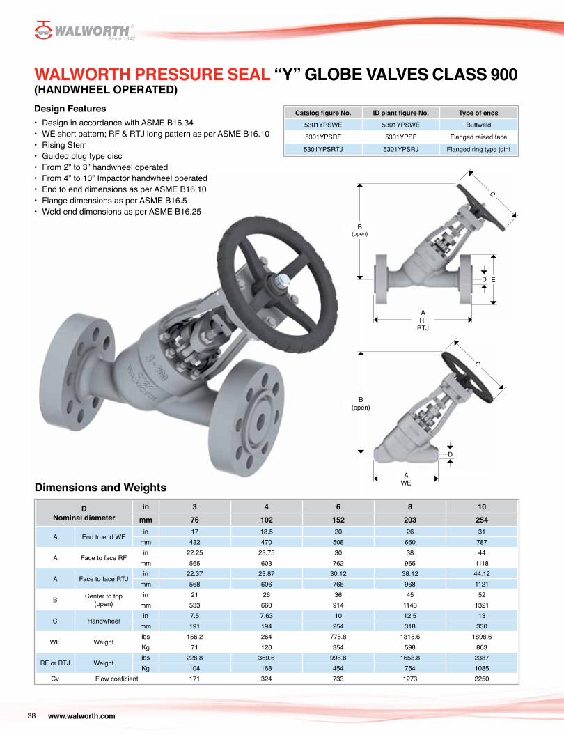
Design Features• Design in accordance with ASME B16.34• WE short pattern; RF & RTJ long pattern as per ASME B16.10• Rising Stem• Guided plug type disc• From 2” to 3” handwheel operated• From 4” to 10” Impactor handwheel operated• End to end dimensions as per ASME B16.10• Flange dimensions as per ASME B16.5• Weld end dimensions as per ASME B16.25
WALWORTH PRESSURE SEAL “Y” GLOBE VALVES CLASS 900(HANDWHEEL OPERATED)
Catalog figure No. ID plant figure No. Type of ends
5301YPSWE 5301YPSWE Buttweld
5301YPSRF 5301YPSF Flanged raised face
5301YPSRTJ 5301YPSRJ Flanged ring type joint
Dimensions and Weights
DNominal diameter
in 3 4 6 8 10mm 76 102 152 203 254
A End to end WEin 17 18.5 20 26 31
mm 432 470 508 660 787
A Face to face RFin 22.25 23.75 30 38 44
mm 565 603 762 965 1118
A Face to face RTJin 22.37 23.87 30.12 38.12 44.12
mm 568 606 765 968 1121
B Center to top (open)
in 21 26 36 45 52mm 533 660 914 1143 1321
C Handwheelin 7.5 7.63 10 12.5 13
mm 191 194 254 318 330
WE Weightlbs 156.2 264 778.8 1315.6 1898.6Kg 71 120 354 598 863
RF or RTJ Weightlbs 228.8 369.6 998.8 1658.8 2387Kg 104 168 454 754 1085
Cv Flow coeficient 171 324 733 1273 2250
39www.walworth.com
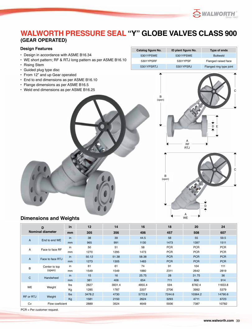
Catalog figure No. ID plant figure No. Type of ends
5301YPSWE 5301YPSWE Buttweld
5301YPSRF 5301YPSF Flanged raised face
5301YPSRTJ 5301YPSRJ Flanged ring type joint
Design Features• Design in accordance with ASME B16.34• WE short pattern; RF & RTJ long pattern as per ASME B16.10• Rising Stem• Guided plug type disc• From 12” and up Gear operated• End to end dimensions as per ASME B16.10• Flange dimensions as per ASME B16.5• Weld end dimensions as per ASME B16.25
Dimensions and WeightsD
Nominal diameterin 12 14 16 18 20 24
mm 305 356 406 457 508 607
A End to end WEin 38 39 44.5 58 55 59.5
mm 965 991 1130 1473 1397 1511
A Face to face RFin 50 51 58 PCR PCR PCR
mm 1270 1295 1473 PCR PCR PCR
A Face to face RTJin 50.12 51.38 58.38 PCR PCR PCR
mm 1273 1305 1483 PCR PCR PCR
B Center to top (open)
in 61 61 74 91 104 111mm 1549 1549 1880 2311 2642 2819
C Handwheelin 15 16 25.75 28 31.75 36
mm 381 406 654 711 806 914
WE Weightlbs 2827 3931.4 4855.4 594 8782.4 11833.8Kg 1285 1787 2207 2706 3992 5379
RF or RTJ Weightlbs 3478.2 4730 5772.8 7244.6 10364.2 14790.6Kg 1581 2150 2624 3293 4711 6723
Cv Flow coeficient 2889 3524 4649 5936 7387 10782
WALWORTH PRESSURE SEAL “Y” GLOBE VALVES CLASS 900(GEAR OPERATED)
A RFRTJ
AWE
E
C
C
D
D
B(open)
B(open)
PCR = Per customer request.

B(open)
B(open)
A RFRTJ
AWE
C
C
ED
D
40 www.walworth.com
Catalog figure No. ID plant figure No. Type of ends
5308YPSWE 5308YPSWE Buttweld
5308YPSRF 5308YPSF Flanged raised face
5308YPSRTJ 5308YPSRJ Flanged ring type joint
Design Features• Design in accordance with ASME B16.34• WE short pattern; RF & RTJ long pattern as per ASME B16.10• Rising Stem• Guided plug type disc• From 3” handwheel operated• From 4” to 10” Impactor handwheel operated• End to end dimensions as per ASME B16.10• Flange dimensions as per ASME B16.5• Weld end dimensions as per ASME B16.25
Dimensions and Weights
DNominal diameter
in 3 4 6 8 10
mm 76 102 152 203 254
A End to end WEin 17 18.5 27.75 30 36.25
mm 432 470 705 762 921
B Center to top (open)
in 21 26 36 50 58
mm 533 660 914 1270 1473
C Handwheelin 18 18 24 30 36
mm 457 457 610 762 914
WE Weightlbs 228.8 391.6 1119.8 1867.8 3555.2
Kg 104 178 509 849 1616
RTJ or RF Weightlbs 326 537 1443 2387 4426
Kg 148 244 656 1085 2012
Cv Flow coeficient 158 281 639 1272 2025
WALWORTH PRESSURE SEAL “Y” GLOBE VALVES CLASS 1500(HANDWHEEL OPERATED)
PCR = Per customer request.

41www.walworth.com
Catalog figure No. ID plant figure No. Type of ends
5308YPSWE 5308YPSWE Buttweld
5308YPSRF 5308YPSF Flanged raised face
5308YPSRTJ 5308YPSRJ Flanged ring type joint
Design Features• Design in accordance with ASME B16.34• WE short pattern; RF & RTJ long pattern as per ASME B16.10• Rising Stem• Guided plug type disc• From 12” and up Gear operated• End to end dimensions as per ASME B16.10• Flange dimensions as per ASME B16.5• Weld end dimensions as per ASME B16.25
Dimensions and Weights
WALWORTH PRESSURE SEAL “Y” GLOBE VALVES CLASS 1500(GEAR OPERATED)
DNominal diameter
in 12 14 16 18 20 24
mm 12 14 16 18 20 24
A End to end WEin 43 51 54 54.5 54.5 59.5
mm 1092 1295 1372 1384 1384 1511
B Center to top (open)
in 65 65 83 89 97 115
mm 1651 1651 2108 2261 2464 2921
C Handwheelin 36 36 36 36 36 36
mm 914 914 914 914 914 914
WE Weightlbs 5451.6 7436 10863.6 13142.8 15807 20158.6
Kg 2478 3380 4938 5974 7185 9163
RTJ or RF Weightlbs 6785 9315 13361 16390 19901 25802
Kg 3084 4234 6073 7450 9046 11728
Cv Flow coeficient 2889 3492 4615 5094 6480 9374
A RFRTJ
AWE
E
C
C
D
D
B(open)
B(open)
PCR = Per customer request.

42 www.walworth.com
Design Features• Design in accordance with ASME B16.34• WE short pattern; RF & RTJ long pattern as per ASME B16.10• Rising Stem• Guided plug type disc• From 2” and up Gear Operated. operated• End to end dimensions as per ASME B16.10• Flange dimensions as per ASME B16.5• Weld end dimensions as per ASME B16.25
Dimensions and Weights
WALWORTH PRESSURE SEAL “Y” GLOBE VALVES CLASS 2500(GEAR OPERATED)
DNominal diameter
in 3 4 6 8 10 12 14 16 18 20 24
mm 76 102 152 203 254 305 356 406 457 508 607
A End to end WEin 17 18.5 24 30 36 41 48.75 48.75 58 58 68
mm 432 470 610 762 914 1041 1238 1238 1473 1473 1727
B Center to top (open)
in 21 26 40 50 58 70 74 74 99 99 115
mm 533 660 1016 1270 1473 1778 1880 1880 2515 2515 2921
C Handwheelin 18 18 24 30 36 36 42 42 42 42 42
mm 457 457 610 762 914 914 1067 1067 1067 1067 1067
RTJ or RF Weightlbs 757 977 1670 2486 4092 6519 10982 PCR PCR PCR PCR
Kg 344 444 759 1130 1860 2963 4992 PCR PCR PCR PCR
WE Weightlbs 591.8 723.8 1249.6 1841.4 3124 4670.6 8386.4 9539.2 11642.4 13866.6 18319.4
Kg 269 329 568 837 1420 2123 3812 4336 5292 6303 8327
Cv Flow coeficient 136 226 517 915 1486 2131 2610 3460 4436 5547 7342
Catalog figure No. ID plant figure No. Type of ends
5563PSWE 5563PSWE Buttweld
5563PSRF 5563PSF Flanged raised face
5563PSRTJ 5563PSRJ Flanged ring type joint
A RFRTJ
AWE
E
C
C
D
D
B(open)
B(open)
PCR = Per customer request.

43www.walworth.com
WALWORTH PRESSURE SEAL TILTING DISC CHECK VALVES
Design Features1 Design in accordance with ASME B16.34.2 Designed to close quickly and quitely. It minimize
damage due slamming or noise due vibration caused due high velocity reverse flow before completion of closing. Design also suitable for low pressure drop.
3 Cover retainer is used to help by tightening the retainer bolt/nuts to seal bonnet-bonnet gasket against body inlay.
4 Pressure seal gasket made from soft carbon steel (silver platted) or stainless steel for corrosion resistance and avoid galling. The angular relationship in between pressure seal gasket and body utilize forces generated by pressure line to increase gasket sealing effect and long life service. Graphite gasket is available upon request.
5 Bonnet encapsulated inside the upper side of the body is designed with precision machined sealing surfaces to fit against pressure seal gasket surface to utilize forces coming from line pressure to seal the complete set body-bonnet-gasket. Bonnet retains the packing system and incorporate also integral back seat system.
6 Segmented thrust ring made from hardened steel absorb all internal forces coming from the internal pressure and hold the complete set bonnet-gasket-spacer ring.
7 Spacer ring prevent deformation when pressures push the complete set bonnet-gasket against segmented thrust ring.
8 Body made from carbon steel or alloy steel are manufactured with overlay made from stainless steel in a band inside the body where contact is made in between gasket and body to improve a better seal and increase life of sealing area due provided corrosion resistance.
9 Seat ring with stellite 6 overlay for better sealing service provide wear, abrasion and erosion resistance. Seat ring is welded to the body to provide tight joint.
10 Sealing areas of the disc with stellite 6 overlay for better operation service. Other sealing surfaces materials can be provided upon request.
11 Damper and counterweight options also available as per Customer request.
12 Test in accordance with API-598.CAUTION: install this valve in a horizontal position only. Contact WALWORTH for other installation orientations.
Cover Retainer
Disc
Gasket
Seat Ring
3
10
4
9
7
8
5
6
Spacer Ring
Body
Bonnet
Thrust Ring

44 www.walworth.com
WALWORTH PRESSURE SEAL TILTING DISC CHECK VALVESFollowing table shows the most common bill of materials for a pressure seal Tilting Disc Check valve. There are many other combinations of base material and trim, please refer to other sections of this catalog for additional information.
Regular Bill of MaterialsNo. Description 9CR-1MO-V
1 Body ASTM A217 GR. C12A
2 Body inlay 309 STAINLESS STEEL (not shown)
3 Segmental thrust ring AISI 410
4 Spacer ring AISI 410
5 Bonnet retainer ASTM A-515 GR. 70
6 Seat ring Co-Cr-W OVERLAY
7 Bonnet ASTM A-217 GR. C12A or ASTM A182 GR. F91
8 Gasket WILD STEEL (100 HB) SILVER PLATED
9 Tilting disc ASTM A-351 GR. CF8M Co-Cr-W overlay
10 Bonnet stud ASTM A-193 GR. B16
11 Bonnet nut ASTM A-194 GR. 7
12 Hinge pin ASTM A276 GR. 410
13 Bushing AISI 1045
14 Arm support ASTM A217 GR. C12A
15 Hex screw AISI 316
11
10
15
14
12
13
1
5
3
4
8
7
9
6

45www.walworth.com
WALWORTH PRESSURE SEAL TILTING DISC CHECK VALVES CLASS 600
Design Features• Design in accordance with ASME B16.34.• WE short pattern; RF & RTJ long pattern as per ASME B16.10.• Tilting type disc.• End to end dimensions as per ASME B16.10.• Flange dimensions as per ASME B16.5.• Weld end dimensions as per ASME B16.25.
Catalog figure No. ID plant figure No. Type of ends
5350PSTDWE 5350PSTDWE Buttweld
5350PSTDRF 5350PSTDF Flanged raised face
5350PSTDRTJ 5350PSTDRJ Flanged ring type joint
Dimensions and Weights
DNominal diameter
in 2 2.5 3 4 6 8 10 12 14 16 18 20 24
mm 51 63 76 102 152 203 254 305 356 406 457 508 607
A End to end WEin 8.5 8.5 10 12 18 23 28 32 35 39 43 47 55
mm 216 216 254 305 457 584 711 813 889 991 1092 1194 1397
A Face to face RFin 11.5 13 14 17 22 26 31 33 35 39 43 47 55
mm 292 330 356 432 559 660 787 838 889 991 1092 1194 1397
A Face to face RTJin 11.62 13.12 14.12 17.12 22.12 26.12 31.12 33.12 35.12 39.12 43.12 47.25 55.38
mm 295 333 359 435 562 663 790 841 892 994 1095 1200 1407
B Center to top(open)
in 7.5 7.5 7.5 8.5 9.5 12 15 17 18 16 24 26 31mm 191 191 191 216 241 305 381 432 457 406 610 660 787
WE Weightlbs 66 70.4 74.8 125.4 259.6 488.4 778.8 1243 1526.8 2026.2 2369.4 3768.6 7106Kg 30 32 34 57 118 222 354 565 694 921 1077 1713 3230
RF or RTJ Weightlbs 83.6 96.8 107.8 200.2 420.2 717.2 1133 1672 2024 3179 3737.8 5601.2 8296.2Kg 38 44 49 91 191 326 515 760 920 1445 1699 2546 3771
Cv Flow coeficient 101 162 237 433 971 1715 2675 3749 4540 6022 7609 8647 12759
A RFRTJ
AWE
B(open)
B(open)
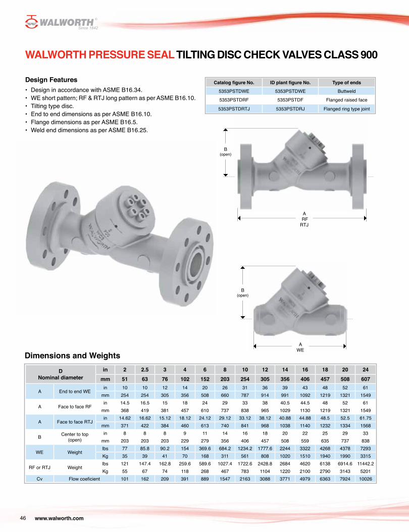
A RFRTJ
AWE
B(open)
B(open)
46 www.walworth.com
DNominal diameter
in 2 2.5 3 4 6 8 10 12 14 16 18 20 24mm 51 63 76 102 152 203 254 305 356 406 457 508 607
A End to end WEin 10 10 12 14 20 26 31 36 39 43 48 52 61
mm 254 254 305 356 508 660 787 914 991 1092 1219 1321 1549
A Face to face RFin 14.5 16.5 15 18 24 29 33 38 40.5 44.5 48 52 61
mm 368 419 381 457 610 737 838 965 1029 1130 1219 1321 1549
A Face to face RTJin 14.62 16.62 15.12 18.12 24.12 29.12 33.12 38.12 40.88 44.88 48.5 52.5 61.75
mm 371 422 384 460 613 740 841 968 1038 1140 1232 1334 1568
B Center to top(open)
in 8 8 8 9 11 14 16 18 20 22 25 29 33mm 203 203 203 229 279 356 406 457 508 559 635 737 838
WE Weightlbs 77 85.8 90.2 154 369.6 684.2 1234.2 1777.6 2244 3322 4268 4378 7293Kg 35 39 41 70 168 311 561 808 1020 1510 1940 1990 3315
RF or RTJ Weightlbs 121 147.4 162.8 259.6 589.6 1027.4 1722.6 2428.8 2684 4620 6138 6914.6 11442.2Kg 55 67 74 118 268 467 783 1104 1220 2100 2790 3143 5201
Cv Flow coeficient 101 162 209 391 889 1547 2163 3088 3771 4979 6363 7924 10026
Design Features• Design in accordance with ASME B16.34.• WE short pattern; RF & RTJ long pattern as per ASME B16.10.• Tilting type disc.• End to end dimensions as per ASME B16.10.• Flange dimensions as per ASME B16.5.• Weld end dimensions as per ASME B16.25.
WALWORTH PRESSURE SEAL TILTING DISC CHECK VALVES CLASS 900
Catalog figure No. ID plant figure No. Type of ends
5353PSTDWE 5353PSTDWE Buttweld
5353PSTDRF 5353PSTDF Flanged raised face
5353PSTDRTJ 5353PSTDRJ Flanged ring type joint
Dimensions and Weights

A RFRTJ
A WE
B
B
47www.walworth.com
Catalog figure No. ID plant figure No. Type of ends
5356PSTDWE 5356PSTDWE Buttweld
5356PSTDRF 5356PSTDF Flanged raised face
5356PSTDRTJ 5356PSTDRJ Flanged ring type joint
Design Features• Design in accordance with ASME B16.34.• WE short pattern; RF & RTJ long pattern as per ASME B16.10.• Tilting type disc.• End to end dimensions as per ASME B16.10.• Flange dimensions as per ASME B16.5.• Weld end dimensions as per ASME B16.25.
Dimensions and Weights
WALWORTH PRESSURE SEAL TILTING DISC CHECK VALVES CLASS 1500
DNominal diameter
in 2 2.5 3 4 6 8 10 12 14 16 18 20 24mm 51 63 76 102 152 203 254 305 356 406 457 508 607
A End to end WEin 8.5 10 12 16 22 28 34 39 42 47 52 56 58
mm 216 254 305 406 559 711 864 991 1067 1194 1321 1422 1473
A Face to face RFin 14.5 16.5 18.5 21.5 27.75 32.75 39 44.5 49.5 54.5 60.5 65.5 76.5
mm 368 419 470 546 705 832 991 1130 1257 1384 1537 1664 1943
A Face to face RTJin 14.62 16.62 18.62 21.62 28 33.13 39.38 45.12 50.25 55.38 61.38 66.38 77.62
mm 371 422 473 549 711 842 1000 1146 1276 1407 1559 1686 1972
B Center to top(open)
in 8 8 8 9 11 14 16 19 21 23 26 30 35mm 203 203 203 229 279 356 406 483 533 584 660 762 889
WE Weightlbs 79.2 85.8 90.2 160.6 380.6 719.4 1379.4 1973.4 2277 2640 3058 4378 6820Kg 36 39 41 73 173 327 627 897 1035 1200 1390 1990 3100
RF or RTJ Weightlbs 129.8 158.4 187 305.8 710.6 1238.6 2250.6 3306.6 3216.4 5137 6349.2 8472.2 12463Kg 59 72 85 139 323 563 1023 1503 1462 2335 2886 3851 5665
Cv Flow coeficient 113 181 233 435 988 1719 2404 3432 4190 5533 7071 8805 11140

48 www.walworth.com
Catalog figure No. ID plant figure No. Type of ends
5566PSTDWE 5566PSTDWE Buttweld
5566PSTDRF 5566PSTDF Flanged raised face
5566PSTDRTJ 5566PSTDRJ Flanged ring type joint
Design Features• Design in accordance with ASME B16.34.• WE short pattern; RF & RTJ long pattern as per ASME B16.10.• Tilting type disc.• End to end dimensions as per ASME B16.10.• Flange dimensions as per ASME B16.5.• Weld end dimensions as per ASME B16.25.
Dimensions and Weights
WALWORTH PRESSURE SEAL TILTING DISC CHECK VALVES CLASS 2500
DNominal diameter
in 2 2.5 3 4 6 8 10 12 14 16 18 20 24mm 51 63 76 102 152 203 254 305 356 406 457 508 607
A End to end WEin 11 13 14.5 18 24 30 36 41 44 48 53 56 58
mm 279 330 368 457 610 762 914 1041 1118 1219 1346 1422 1473
A Face to face RFin 8.5 8.5 8.5 11.5 13 16 18 21 23.5 26 29 32 36
mm 216 216 216 292 330 406 457 533 597 660 737 813 914
A Face to face RTJin 110 118.8 125.4 189.2 479.6 829.4 1399.2 2316.6 2873.2 4510 5011.6 5108.4 11880
mm 50 54 57 86 218 377 636 1053 1306 2050 2278 2322 5400
B Center to top (open)
in 101 125 125 208 501 889 1441 2069 2534 2940 3771 4617 6791mm 191 191 191 216 241 305 381 432 457 406 610 660 787
WE Weightlbs 110 119 125 189 480 830 1400 2317 PCR PCR PCR PCR PCRKg 50 54 57 86 218 377 636 1053 PCR PCR PCR PCR PCR
RF or RTJ Weightlbs 187 229 290 442 900 1474 2367 4165 PCR PCR PCR PCR PCRKg 85 104 132 201 409 670 1076 1893 PCR PCR PCR PCR PCR
Cv Flow coeficient 101 162 237 433 971 1715 2675 3749 4540 6022 7609 8647 12759
A RFRTJ
A WE
B
B

49www.walworth.com
WALWORTH PRESSURE SEAL SWING CHECK VALVES
Design Features1 Design in accordance with ASME B16.34.2 Designed to close quickly and quitely.3 Cover retainer is used to help by tightening the retainer bolt/nuts
to seal bonnet-bonnet gasket against body inlay.4 Pressure seal gasket made from soft carbon steel (silver platted)
or stainless steel for corrosion resistance and avoid galling. The angular relationship in between pressure seal gasket and body utilize forces generated by pressure line to increase gasket sealing effect and long life service. Graphite gasket is available upon request.
5 Bonnet encapsulated inside the upper side of the body is designed with precision machined sealing surfaces to fit against pressure seal gasket surface to utilize forces coming from line pressure to seal the complete set body-bonnet-gasket. Bonnet retains the packing system and incorporate also integral back seat system.
6 Segmented thrust ring made from hardened steel absorb all internal forces coming from the internal pressure and hold the complete set bonnet-gasket-spacer ring.
7 Spacer ring prevent deformation when pressures push the complete set bonnet-gasket against segmented thrust ring.
8 Body made from carbon steel or alloy steel are manufactured with overlay made from stainless steel in a band inside the body where contact is made in between gasket and body to improve a better seal and increase life of sealing area due provided corrosion resistance.
9 Seat ring with stellite 6 overlay for better sealing service provide wear, abrasion and erosion resistance. Seat ring is welded to the body to provide tight joint.
10 Sealing areas of the disc with stellite 6 overlay for better operation service. Other sealing surfaces materials can be provided upon request.
11 Damper and counterweight options also available as per Customer request.
12 Test in accordance with API-598.13 Caution: install this valve in a horizontal position only. Contact
Walworth for other installation orientations.
Cover
Spacer Ring
Gasket
Bonnet
3
6
4
5
8
9
7
Body
Seat Ring
Thrust Ring

50 www.walworth.com
WALWORTH PRESSURE SEAL SWING CHECK VALVESFollowing table shows the most common bill of materials for a pressure seal Swing Check valve. There are many other combinations of base material and trim, please refer to other sections of this catalog for additional information.
No. DESCRIPTION 316 STAINLESS STEEL
1 BODY ASTM A351 GR. CF8M
2 BODY INLAY INTEGRAL
3 SEGMENTAL THRUST RING AISI 316
4 SPACER RING AISI 316
5 BONNET RETAINER ASTM A-515 GR. 70
6 SEAT RING INTEGRAL
7 BONNET ASTM A-351 GR. CF8M
8 GASKET ASTM A-182 GR. F316
9 SWING TYPE DISC ASTM A-351 GR. CF8M Co-Cr-W OVERLAY
10 ARM ASTM A351 GR. CF8M
11 ARM SUPPorT ASTM A351 GR. CF8M
12 HINGE PIN ASTM A276 GR 316
13 BONNET STUD ASTM A-193 GR. B8 CLASS 2
14 BONNET NUT ASTM A-194 GR. 8
15 DISC NUT ASTM A-276 GR. 316
16 HEX SCREW ASTM A-276 GR. 316
2
Regular Bill of Materials
11
16
11
6
12
1
13
5
3
4
8
7
10
15
9
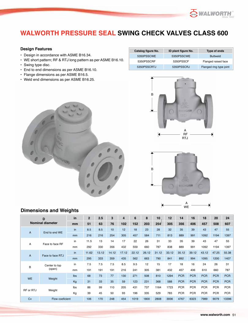
51www.walworth.com
WALWORTH PRESSURE SEAL SWING CHECK VALVES CLASS 600
Design Features• Design in accordance with ASME B16.34.• WE short pattern; RF & RTJ long pattern as per ASME B16.10.• Swing type disc.• End to end dimensions as per ASME B16.10.• Flange dimensions as per ASME B16.5.• Weld end dimensions as per ASME B16.25.
Catalog figure No. ID plant figure No. Type of ends
5350PSSCWE 5350PSSCWE Buttweld
5350PSSCRF 5350PSSCF Flanged raised face
5350PSSCRTJ 5350PSSCRJ Flanged ring type joint
Dimensions and WeightsD
Nominal diameterin 2 2.5 3 4 6 8 10 12 14 16 18 20 24
mm 51 63 76 102 152 203 254 305 356 406 457 508 607
A End to end WEin 8.5 8.5 10 12 18 23 28 32 35 39 43 47 55
mm 216 216 254 305 457 584 711 813 889 991 1092 1194 1397
A Face to face RFin 11.5 13 14 17 22 26 31 33 35 39 43 47 55
mm 292 330 356 432 559 660 787 838 889 991 1092 1194 1397
A Face to face RTJin 11.62 13.12 14.12 17.12 22.12 26.12 31.12 33.12 35.12 39.12 43.12 47.25 55.38
mm 295 333 359 435 562 663 790 841 892 994 1095 1200 1407
B Center to top (open)
in 7.5 7.5 7.5 8.5 9.5 12 15 17 18 16 24 26 31
mm 191 191 191 216 241 305 381 432 457 406 610 660 787
WE Weightlbs 68 73 77 130 271 508 810 1294 PCR PCR PCR PCR PCR
Kg 31 33 35 59 123 231 368 588 PCR PCR PCR PCR PCR
RF or RTJ Weightlbs 86 99 110 205 431 737 1164 1723 PCR PCR PCR PCR PCR
Kg 39 45 50 93 196 335 529 783 PCR PCR PCR PCR PCR
Cv Flow coeficient 106 170 248 454 1019 1800 2808 3936 4767 6323 7989 9079 13396
A RFRTJ
A WE
B
B

A RFRTJ
A WE
B
B
52 www.walworth.com
DNominal diameter
in 2 2.5 3 4 6 8 10 12 14 16 18 20 24mm 51 63 76 102 152 203 254 305 356 406 457 508 607
A End to end WEin 10 10 12 14 20 26 31 36 39 43 48 52 61
mm 254 254 305 356 508 660 787 914 991 1092 1219 1321 1549
A Face to face RFin 14.5 16.5 15 18 24 29 33 38 40.5 44.5 48 52 61
mm 368 419 381 457 610 737 838 965 1029 1130 1219 1321 1549
A Face to face RTJin 14.62 16.62 15.12 18.12 24.12 29.12 33.12 38.12 40.88 44.88 48.5 52.5 61.75
mm 371 422 384 460 613 740 841 968 1038 1140 1232 1334 1568
B Center to top (open)
in 8 8 8 9 11 14 16 18 20 22 25 29 33mm 203 203 203 229 279 356 406 457 508 559 635 737 838
WE Weightlbs 79 90 95 161 385 711 1283 1848 PCR PCR PCR PCR PCRKg 36 41 43 73 175 323 583 840 PCR PCR PCR PCR PCR
RF or RTJ Weightlbs 123 152 167 266 605 1054 1771 2499 PCR PCR PCR PCR PCRKg 56 69 76 121 275 479 805 1136 PCR PCR PCR PCR PCR
Cv Flow coeficient 106 170 219 410 933 1624 2271 3242 3959 5227 6681 8320 10527
Design Features• Design in accordance with ASME B16.34.• WE short pattern; RF & RTJ long pattern as per ASME B16.10.• Swing type disc.• End to end dimensions as per ASME B16.10.• Flange dimensions as per ASME B16.5.• Weld end dimensions as per ASME B16.25.
WALWORTH PRESSURE SEAL SWING CHECK VALVES CLASS 900
Catalog figure No. ID plant figure No. Type of ends
5353PSSCWE 5353PSSCWE Buttweld
5353PSSCRF 5353PSSCF Flanged raised face
5353PSSCRTJ 5353PSSCRJ Flanged ring type joint
Dimensions and Weights

A RFRTJ
A WE
B
B
53www.walworth.com
Catalog figure No. ID plant figure No. Type of ends
5356PSSCWE 5356PSSCWE Buttweld
5356PSSCRF 5356PSSCF Flanged raised face
5356PSSCRTJ 5356PSSCRJ Flanged ring type joint
Design Features• Design in accordance with ASME B16.34.• WE short pattern; RF & RTJ long pattern as per ASME B16.10.• Swing type disc.• End to end dimensions as per ASME B16.10.• Flange dimensions as per ASME B16.5.• Weld end dimensions as per ASME B16.25.
Dimensions and Weights
WALWORTH PRESSURE SEAL SWING CHECK VALVES CLASS 1500
DNominal diameter
in 2 2.5 3 4 6 8 10 12 14 16 18 20 24mm 51 63 76 102 152 203 254 305 356 406 457 508 607
A End to end WEin 8.5 10 12 16 22 28 34 39 42 47 52 56 58
mm 216 254 305 406 559 711 864 991 1067 1194 1321 1422 1473
A Face to face RFin 14.5 16.5 18.5 21.5 27.75 32.75 39 44.5 49.5 54.5 60.5 65.5 76.5
mm 368 419 470 546 705 832 991 1130 1257 1384 1537 1664 1943
A Face to face RTJin 14.62 16.62 18.62 21.62 28 33.13 39.38 45.12 50.25 55.38 61.38 66.38 77.62
mm 371 422 473 549 711 842 1000 1146 1276 1407 1559 1686 1972
B Center to top (open)
in 8 8 8 9 11 14 16 19 21 23 26 30 35mm 203 203 203 229 279 356 406 483 533 584 660 762 889
WE Weightlbs 81 90 95 167 396 748 1434 2053 PCR PCR PCR PCR PCRKg 37 41 43 76 180 340 652 933 PCR PCR PCR PCR PCR
RF or RTJ Weightlbs 130 163 189 312 726 1267 2306 3386 PCR PCR PCR PCR PCRKg 59 74 86 142 330 576 1048 1539 PCR PCR PCR PCR PCR
Cv Flow coeficient 118 181 244 456 1037 1804 2524 3603 4399 5809 7424 9245 11697

54 www.walworth.com
Catalog figure No. ID plant figure No. Type of ends
5566PSSCWE 5566PSSCWE Buttweld
5566PSSCRF 5566PSSCF Flanged raised face
5566PSSCRTJ 5566PSSCRJ Flanged ring type joint
Design Features• Design in accordance with ASME B16.34.• WE short pattern; RF & RTJ long pattern as per ASME B16.10.• Swing type disc.• End to end dimensions as per ASME B16.10.• Flange dimensions as per ASME B16.5.• Weld end dimensions as per ASME B16.25.
Dimensions and Weights
WALWORTH PRESSURE SEAL SWING CHECK VALVES CLASS 2500
DNominal diameter
in 2 2.5 3 4 6 8 10 12 14 16 18 20 24
mm 51 63 76 102 152 203 254 305 356 406 457 508 607
A End to end WEin 11 13 14.5 18 24 30 36 41 44 48 53 56 58
mm 279 330 368 457 610 762 914 1041 1118 1219 1346 1422 1473
A Face to face RFin 8.5 8.5 8.5 11.5 13 16 18 21 23.5 26 29 32 36
mm 216 216 216 292 330 406 457 533 597 660 737 813 914
A Face to face RTJin 110 118.8 125.4 189.2 479.6 829.4 1399.2 2316.6 2873.2 4510 5011.6 5108.4 11880
mm 50 54 57 86 218 377 636 1053 1306 2050 2278 2322 5400
B Center to top (open)
in 106 131 131 218 526 933 1513 2172 2660 3087 3959 4847 7130mm 191 191 191 216 241 305 381 432 457 406 610 660 787
WE Weightlbs 114 123 130 196 499 862 1454 2409 PCR PCR PCR PCR PCRKg 52 56 59 89 227 392 661 1095 PCR PCR PCR PCR PCR
RF or RTJ Weightlbs 191 233 295 449 920 1507 2422 4257 PCR PCR PCR PCR PCRKg 87 106 134 204 418 685 1101 1935 PCR PCR PCR PCR PCR
Cv Flow coeficient 101 162 237 433 971 1715 2675 3749 4540 6022 7609 8647 12759
A RFRTJ
A WE
B
B

55www.walworth.com
WALWORTH PRESSURE SEAL LIFT CHECK VALVES
1 Design in accordance with ASME B16.34.2 Designed to close quickly and quitely. It minimize damage due
slamming or noise due vibration caused due high velocity reverse flow before completion of closing.
3 Cover retainer is used to help by tightening the retainer bolt/nuts to seal bonnet-bonnet gasket against body inlay.
4 Pressure seal gasket made from soft carbon steel (silver platted) or stainless steel for corrosion resistance and avoid galling. The angular relationship in between pressure seal gasket and body utilize forces generated by pressure line to increase gasket sealing effect and long life service. Graphite gasket is available upon request.
5 Bonnet encapsulated inside the upper side of the body is designed with precision machined sealing surfaces to fit against pressure seal gasket surface to utilize forces coming from line pressure to seal the complete set body-bonnet-gasket. Bonnet retains the packing system and incorporate also integral back seat system.
6 Segmented thrust ring made from hardened steel absorb all internal forces coming from the internal pressure and hold the complete set bonnet-gasket-spacer ring.
7 Spacer ring prevent deformation when pressures push the complete set bonnet-gasket against segmented thrust ring.
Design Features8 Body made from carbon steel or alloy steel are manufactured with
overlay made from stainless steel in a band inside the body where contact is made in between gasket and body to improve a better seal and increase life of sealing area due provided corrosion resistance.
9 Body guide ribs hardfaced on some sizes of globe, stop check and angle globe patterns provide body guiding for disc or piston assemblies.
10 Seat ring with stellite 6 overlay for better sealing service provide wear, abrasion and erosion resistance. Seat ring is welded to the body to provide tight joint.
11 Body guided plug disc designed to avoid vibration and/or misalignement during opening or closing. Sealing areas of the disc with stellite 6 overlay for better operation service. Other sealing surfaces materials can be provided upon request.
12 Valve can be provided with spring as per Customer request.13 Equilizar Pipe as per Customer Request14 Damper and counterweight options also available as per
Customer request.15 Piston Check valve works also to offer protection in case of back
flow due lost of pressure.16 Valve suitable for horizontal or vertical position (when spring is
requested).17 Test in accordance with API-598.
Cover
Thrust Ring
Equilizaer Pipe
Gasket
Bonnet
3
6
4
13
5
11
10
8
7
12
Disc
Seat Ring
Body
Spacer Ring
Spring (optional)

56 www.walworth.com
WALWORTH PRESSURE SEAL LIFT CHECK VALVESFollowing table shows the most common bill of materials for a pressure seal Swing Check valve. There are many other combinations of base material and trim, please refer to other sections of this catalog for additional information.
w DESCRIPTION 347 STAINLESS STEEL
1 BODY ASTM A351 GR. CF8C
2 BODY INLAY INTEGRAL (not shown)
3 SEGMENTAL THRUST RING AISI 316
4 SPACER RING AISI 316
5 BONNET RETAINER ASTM A-515 GR. 70
6 SEAT RING INTEGRAL
7 BONNET ASTM A-351 GR. CF8C
8 GASKET ASTM A-182 GR. F347
9 PISTON DISC ASTM A-351 GR. CF8C Co-Cr-W OVERLAY
10 BONNET STUD ASTM A-193 GR. B8 CLASS 2
11 BONNET NUT ASTM A-194 GR. 8
12 EQUILIZAR PIPE AISI-347
13 SPRING AS PER CUSTOMER REQUEST
Regular Bill of Materials
11
10
5
3
13
5
9
8
6
7
12
1
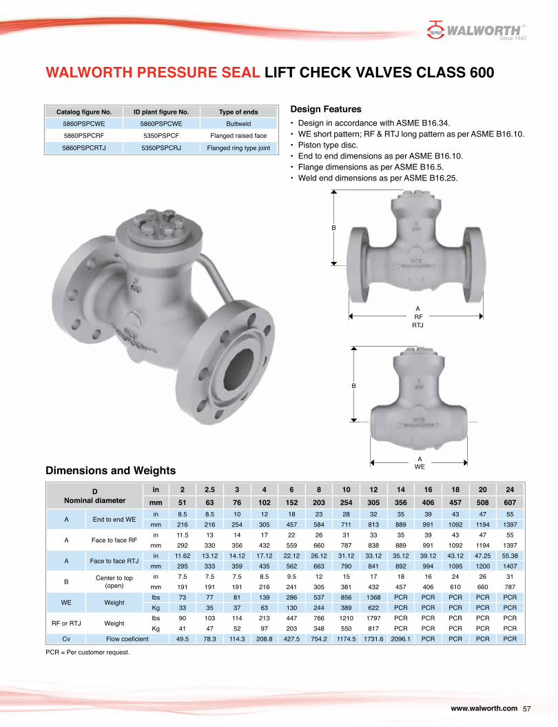
57www.walworth.com
WALWORTH PRESSURE SEAL LIFT CHECK VALVES CLASS 600
Design Features• Design in accordance with ASME B16.34.• WE short pattern; RF & RTJ long pattern as per ASME B16.10.• Piston type disc.• End to end dimensions as per ASME B16.10.• Flange dimensions as per ASME B16.5.• Weld end dimensions as per ASME B16.25.
Catalog figure No. ID plant figure No. Type of ends
5860PSPCWE 5860PSPCWE Buttweld
5860PSPCRF 5350PSPCF Flanged raised face
5860PSPCRTJ 5350PSPCRJ Flanged ring type joint
Dimensions and Weights
DNominal diameter
in 2 2.5 3 4 6 8 10 12 14 16 18 20 24mm 51 63 76 102 152 203 254 305 356 406 457 508 607
A End to end WEin 8.5 8.5 10 12 18 23 28 32 35 39 43 47 55
mm 216 216 254 305 457 584 711 813 889 991 1092 1194 1397
A Face to face RFin 11.5 13 14 17 22 26 31 33 35 39 43 47 55
mm 292 330 356 432 559 660 787 838 889 991 1092 1194 1397
A Face to face RTJin 11.62 13.12 14.12 17.12 22.12 26.12 31.12 33.12 35.12 39.12 43.12 47.25 55.38
mm 295 333 359 435 562 663 790 841 892 994 1095 1200 1407
B Center to top (open)
in 7.5 7.5 7.5 8.5 9.5 12 15 17 18 16 24 26 31mm 191 191 191 216 241 305 381 432 457 406 610 660 787
WE Weightlbs 73 77 81 139 286 537 856 1368 PCR PCR PCR PCR PCRKg 33 35 37 63 130 244 389 622 PCR PCR PCR PCR PCR
RF or RTJ Weightlbs 90 103 114 213 447 766 1210 1797 PCR PCR PCR PCR PCRKg 41 47 52 97 203 348 550 817 PCR PCR PCR PCR PCR
Cv Flow coeficient 49.5 78.3 114.3 208.8 427.5 754.2 1174.5 1731.6 2096.1 PCR PCR PCR PCR
PCR = Per customer request.
A RFRTJ
A WE
B
B

A RFRTJ
A WE
B
B
58 www.walworth.com
DNominal diameter
in 2 2.5 3 4 6 8 10 12 14 16 18 20 24mm 51 63 76 102 152 203 254 305 356 406 457 508 607
A End to end WEin 10 10 12 14 20 26 31 36 39 43 48 52 61
mm 254 254 305 356 508 660 787 914 991 1092 1219 1321 1549
A Face to face RFin 14.5 16.5 15 18 24 29 33 38 40.5 44.5 48 52 61
mm 368 419 381 457 610 737 838 965 1029 1130 1219 1321 1549
A Face to face RTJin 14.62 16.62 15.12 18.12 24.12 29.12 33.12 38.12 40.88 44.88 48.5 52.5 61.75
mm 371 422 384 460 613 740 841 968 1038 1140 1232 1334 1568
B Center to top (open)
in 8 8 8 9 11 14 16 18 20 22 25 29 33mm 203 203 203 229 279 356 406 457 508 559 635 737 838
WE Weightlbs 86 95 99 169 407 752 1357 1956 PCR PCR PCR PCR PCRKg 39 43 45 77 185 342 617 889 PCR PCR PCR PCR PCR
RF or RTJ Weightlbs 130 156 172 275 627 1096 1846 2607 PCR PCR PCR PCR PCRKg 59 71 78 125 285 498 839 1185 PCR PCR PCR PCR PCR
Cv Flow coeficient 41 63 93 173 392 681 1084 1548 1890 PCR PCR PCR PCR
Design Features• Design in accordance with ASME B16.34• WE short pattern; RF & RTJ long pattern as per ASME B16.10• Piston type disc• End to end dimensions as per ASME B16.10• Flange dimensions as per ASME B16.5• Weld end dimensions as per ASME B16.25
WALWORTH PRESSURE SEAL LIFT CHECK VALVES CLASS 900
Catalog figure No. ID plant figure No. Type of ends
5540PSPCWE 5540PSPCWE Buttweld
5540PSPCRF 5540PSPCF Flanged raised face
5540PSPCRTJ 5540PSPCRJ Flanged ring type joint
Dimensions and Weights
PCR = Per customer request

A RFRTJ
A WE
B
B
59www.walworth.com
Catalog figure No. ID plant figure No. Type of ends
5541PSPCWE 5541PSPCWE Buttweld
5541PSPCRF 5541PSPCF Flanged raised face
5541PSPCRTJ 5541PSPCRJ Flanged ring type joint
Design Features• Design in accordance with ASME B16.34• WE short pattern; RF & RTJ long pattern as per ASME B16.10• Piston type disc• End to end dimensions as per ASME B16.10• Flange dimensions as per ASME B16.5• Weld end dimensions as per ASME B16.25
Dimensions and Weights
WALWORTH PRESSURE SEAL LIFT CHECK VALVES CLASS 1500
DNominal diameter
in 2 2.5 3 4 6 8 10 12 14 16 18 20 24mm 51 63 76 102 152 203 254 305 356 406 457 508 607
A End to end WEin 8.5 10 12 16 22 28 34 39 42 47 52 56 58
mm 216 254 305 406 559 711 864 991 1067 1194 1321 1422 1473
A Face to face RFin 14.5 16.5 18.5 21.5 27.75 32.75 39 44.5 49.5 54.5 60.5 65.5 76.5
mm 368 419 470 546 705 832 991 1130 1257 1384 1537 1664 1943
A Face to face RTJin 14.62 16.62 18.62 21.62 28 33.13 39.38 45.12 50.25 55.38 61.38 66.38 77.62
mm 371 422 473 549 711 842 1000 1146 1276 1407 1559 1686 1972
B Center to top (open)
in 8 8 8 9 11 14 16 19 21 23 26 30 35mm 203 203 203 229 279 356 406 483 533 584 660 762 889
WE Weightlbs 88 95 99 176 418 792 1518 2171 PCR PCR PCR PCR PCRKg 40 43 45 80 190 360 690 987 PCR PCR PCR PCR PCR
RF or RTJ Weightlbs 139 167 189 321 748 1289 2389 3505 PCR PCR PCR PCR PCRKg 63 76 86 146 340 586 1086 1593 PCR PCR PCR PCR PCR
Cv Flow coeficient 41 59 85 151 342 589 938 1339 PCR PCR PCR PCR PCR
PCR = Per customer request

A RFRTJ
A WE
B
B
60 www.walworth.com
Catalog figure No. ID plant figure No. Type of ends
5542PSPCWE 5542PSPCWE Buttweld
5542PSPCRF 5542PSPCF Flanged raised face
5542PSPCRTJ 5542PSPCRJ Flanged ring type joint
Design Features• Design in accordance with ASME B16.34• WE short pattern; RF & RTJ long pattern as per ASME B16.10• Piston type disc• End to end dimensions as per ASME B16.10• Flange dimensions as per ASME B16.5• Weld end dimensions as per ASME B16.25
Dimensions and Weights
PCR = Per customer request
WALWORTH PRESSURE SEAL LIFT CHECK VALVES CLASS 2500
DNominal diameter
in 2 2.5 3 4 6 8 10 12 14 16 18 20 24mm 51 63 76 102 152 203 254 305 356 406 457 508 607
A End to end WEin 11 13 14.5 18 24 30 36 41 44 48 53 56 58
mm 279 330 368 457 610 762 914 1041 1118 1219 1346 1422 1473
A Face to face RTJin 11.125 13.125 14.625 18.125 24.125 30.125 36.125 41.125 PCR PCR PCR PCR PCR
mm 283 333 371 460 613 765 918 1045 PCR PCR PCR PCR PCR
B Center to top (open)
in 8.5 8.5 8.5 11.5 13 16 18 21 23.5 26 29 32 36
mm 216 216 216 292 330 406 457 533 597 660 737 813 914
WE Weightlbs 121 130 139 209 528 913 1540 2548 PCR PCR PCR PCR PCR
Kg 55 59 63 95 240 415 700 1158 PCR PCR PCR PCR PCR
RF or RTJ Weightlbs 198 240 304 462 948 1558 2508 4396 PCR PCR PCR PCR PCR
Kg 90 109 138 210 431 708 1140 1998 PCR PCR PCR PCR PCR
Cv Flow Coeficient 101 162 237 433 971 1715 2675 3749 4540 6022 7609 8647 12759

61www.walworth.com
The WALWORTH standard cast steel pressure seal product line includes many different valves designed to meet most applications.
Special adaptations can be made to meet specific customer requirements. Valves can be supplied with manual handwheel/gear operation, chain wheel, as well as electric, pneumatic and hydraulic actuators.
TYPE OF OPERATIONS
This makes it possible for WALWORTH to furnish valves adapted to the customers special needs such as controlled opening/closing and remote installation.
Valves can also be supplied with a bypass, drain or vent connection, stem extension, position indicators, floor stand mounting as well as a lever and weight system for swing check valves.
Gear OperatorsA manual gear operator is designed with a bevel gear and pinion ratio sized to transmit the required opening/closing torque with normal operator effort on the handwheel. They can be supplied as waterproof units and/or for underground installation with a square operating nut.
Chain Wheel OperationChain Wheels are designed for operating valves installed in remote or inaccessible locations. They can be furnished with roller guides to prevent the chain from jumping off the wheel. Impact type chain wheels are also available to assist in unseating a tightly closed valve
Actuators Valves can be furnished with either electric, pneumatic or hydraulic actuators. The actuators can be furnished as either waterproof and/or explosion proof. The customer must specify such things as open-close speed, maximum differential pressure, service temperature, type of voltage-phase-frequency, air or gas pressure for pneumatic actuators and flow characteristics for hydraulic actuators to be assured of correct performance.
TECHNICAL INFORMATION

62 www.walworth.com
TECHNICAL INFORMATION
Excessive pressure trapped in body center cavity of standard pressure seal gate valves can produce overpressure in this area which make difficult or impossible to open the valve. An equilizer system either internal (equilizer hole or groove) or external (equlizer pipe, relieve valve, drain), may release overpressure to another specific pipe system. In case of globe or check valves, these pressure release fixtures are used also to bypass fluid from the center of the body to another specific area.
In the case of Gate Valves with parallel slide disc or inclusive wedge style (when Customer request a valve to be able to seal simul-taneously in both directions), these valves are designed to seal against a differential pressure in between central cavity of the body and pipe in both directions. However, there is a physical phenomena when the valve is in closed position and then heated; pressure entrapped will overpressurize the body cavity. This is dangerous and can result in failure of the valve. ASME B16.34 (p. 2.3.3) and ASME B31.1 (p. 107.1) request that process plant designer have to ensure not exceed the rated pressure-temperature. For this, shall be specified by purchaser an equilizer system (either internal or external) to relieve overpressurized fluid to upstream or a relieve valve which can release overpressure to some other piping system. When an equilizer system or a relieve valve is used, valve becomes from bi-directional to unidirectional design and service.
Equilizer hole.- A hole drilled of 1/8” diameter or a groove 1/8” wide and deep is located in the upstream seat area of the disc wedge or parallel slide disc to equilize pressure.
RELIEVE PRESSURE ACCESORIES
Drains or Vents.- WALWORTH valves can be supplied upon request with drains and / or vents. WALWORTH design is made with pipe and forge valve socket welded to the body. However, Customer can request specific design to fit their needs.
Hole 1/8” ø
“G”
downstream
downstream
upstream
upstream

63www.walworth.com
Equalizer pipe.- An external equilizer pipe can be supplied to connect bonnet cavity to downstream side of the valve.
By-Pass valve.- Single by-pass valves can be connected from center cavity of the body to downstream side of the valve to equilize pressure.
TECHNICAL INFORMATION
Double By-Pass.- As per Customer requirements, WALWORTH gate valves can be manufactured with double By-Pass to permit deviate pressure from upstream to downstream side or from body cavity to downstream side of the valve.

64 www.walworth.com
TECHNICAL INFORMATION
SOLID WEDGE.- Standard valves are designed with solid rigid wedge, but when pressure and temperature is involve, the rigidity of the wedge promote leak or bind in closed position.
The WALWORTH standard gate valve is designed with flexible wedge to help set seat rings-wedge to seal easily in closed position absorving dimensional changes due pressure or temperature operation and avoid stuck wedge.
Flexible wedge is also suitable to avoid stuck wedge due their flexibility.
WEDGE / DISC STYLES
PARALLEL SLIDE DISC.- For applications where temperature involved may expand the stem and cause disc binding, parallel slide disc is recommended because the design use the fluid upstream to assist sealing downstream side of the valve.
During closing operation, close tolerances and guides design permit disc sliding smoothly against the seat rings to avoid wearing or seal areas damage. Stellite seal overalys on sealing areas are recommended for the majority of applications for pressure seal valves, except nuclear plants or those where Co is prohibited.
One or more Springs located in the center of the disc keep tight sealing in between disc and seat rings as per forces calculated; but also permit auto alignement due vibrations or dimensional changes because temperature or prressure.
T slot shape helps to align stem at the center of the valve.

65www.walworth.com
CAST STEEL ASTM A 216 GR WCB
PRESSURE-TEMPERATURE RATINGS
Note: Upon prolonged exposure to temperatures above 800°F, the carbide phase of steel may be converted to graphite. Permissible, but not recommended for prolonged use above 800°F.
CAST STEEL ASTM A 217 GR WC6
(a) Flanged-end valve ratings terminate at 1,000°F (538°C).
°F Temperature °CMAXIMUM ALLOWABLE NON-SHOCK WorKING PRESSURE IN PSIG BY CLASS
150 300 600 900 1500 2500-20 to 100 -29 to 38 285 740 1,480 2,220 3,705 6,170
200 93 260 680 1,360 2,035 3,395 5,655
300 149 230 655 1,310 1,965 3,270 5,450
400 204 200 635 1,265 1,900 3,170 5,280
500 260 170 605 1,205 1,810 3,015 5,025
600 316 140 570 1,135 1,705 2,840 4,730
650 343 125 550 1,100 1,650 2,745 4,575
700 371 110 530 1,060 1,590 2,665 4,425
750 399 95 505 1,015 1,520 2,535 4,230
800 427 80 410 825 1,235 2,055 3,430
850 454 65 320 640 955 1,595 2,655
900 482 50 230 460 690 1,150 1,915
950 510 35 135 275 410 685 1,145
1,000 538 20 85 170 255 430 715
°F Temperature °CMAXIMUM ALLOWABLE NON-SHOCK WorKING PRESSURE IN PSIG BY CLASS
150 300 600 900 1500 2500-20 to 100 -29 to 38 290 750 1,500 2,250 3,750 6,250
200 93 260 750 1,500 2,250 3,750 6,250
300 149 230 720 1,445 2,165 3,610 6,015
400 204 200 695 1,385 2,080 3,465 5,775
500 260 170 665 1,330 1,995 3,325 5,540
600 316 140 605 1,210 1,815 3,025 5,040
650 343 125 590 1,175 1,765 2,940 4,905
700 371 110 570 1,135 1,705 2,840 4,730
750 399 95 530 1,065 1,595 2,660 4,430
800 427 80 510 1,015 1,525 2,540 4,230
850 454 65 485 975 1,460 2,435 4,060
900 482 50 450 900 1,350 2,245 3,745
950 510 35 320 640 955 1,595 2,655
1,000 538 20 215 430 650 1,080 1,800
1,050 566 20(a) 145 290 430 720 1,200
1,100 593 20(a) 95 190 290 480 800
1,150 621 20(a) 65 130 195 325 545
1,200 649 15(a) 40 80 125 205 345

66 www.walworth.com
PRESSURE-TEMPERATURE RATINGSCAST STEEL ASTM A 217 GR WC9
(a) Flanged-end valve ratings terminat at 1,000°F.
(a) For welding ends valves only. Flanged ends ratings terminate at 1000°F (538°C).
CAST STEEL ASTM A 217 GR C5
°F Temperature °CMAXIMUM ALLOWABLE NON-SHOCK WorKING PRESSURE IN PSIG BY CLASS
150 300 600 900 1500 2500-20 a 100 -29 a 38 290 750 1,500 2,250 3,750 6,250
200 93 260 750 1,500 2,250 3,750 6,250
300 149 230 730 1,455 2,185 3,640 6,070
400 204 200 705 1,410 2,115 3,530 5,880
500 260 170 665 1,330 1,995 3,325 5,540
600 316 140 605 1,210 1,815 3,025 5,040
650 343 125 590 1,175 1,765 2,940 4,905
700 371 110 570 1,135 1,705 2,840 4,730
750 399 95 530 1,065 1,595 2,660 4,430
800 427 80 510 1,015 1,525 2,540 4,230
850 454 65 485 975 1,460 2,435 4,060
900 482 50 450 900 1,350 2,245 3,745
950 510 35 385 755 1,160 1,930 3,220
1,000 538 20 265 535 800 1,335 2,230
1,050 566 20(a) 175 350 525 875 1,455
1,100 593 20(a) 110 220 330 550 915
1,150 621 20(a) 70 135 205 345 570
1,200 649 15(a) 40 80 125 205 345
°F Temperature °CMAXIMUM ALLOWABLE NON-SHOCK WorKING PRESSURE IN PSIG BY CLASS
150 300 600 900 1500 2500-20 a 100 -29 a 38 290 750 1,500 2,250 3,750 6,250
200 93 260 750 1,500 2,250 3,750 6,250
300 149 230 730 1,455 2,175 3,640 6,070
400 204 200 705 1,410 2,115 3,530 5,880
500 260 170 665 1,330 1,995 3,325 5,540
600 316 140 605 1,210 1,815 3,025 5,040
650 343 125 590 1,175 1,765 2,940 4,905
700 371 110 570 1,135 1,705 2,840 4,730
750 399 95 530 1,065 1,595 2,660 4,430
800 427 80 510 1,015 1,525 2,540 4,230
850 454 65 485 975 1,460 2,435 4,060
900 482 50 375 745 1,120 1,870 3,115
950 510 35 275 550 825 1,370 2,285
1,000 538 20 200 400 595 995 1,655
1,050 566 20(a) 145 290 430 720 1,200
1,100 593 20(a) 100 200 300 495 830
1,150 621 20(a) 60 125 185 310 515
1,200 649 15(a) 35 70 105 170 285

67www.walworth.com
(a) For welding ends valves only. Flanged ends ratings terminate at 1000°F (538°C).
PRESSURE-TEMPERATURE RATINGSCAST STEEL ASTM A 217 GR C12
CAST STEEL ASTM A 217 GR C12-A
(a) For welding ends valves only. Flanged ends ratings terminate at 1000°F (538°C).
°F Temperature °CMAXIMUM ALLOWABLE NON-SHOCK WorKING PRESSURE IN PSIG BY CLASS
150 300 600 900 1,500 2500-20 a 100 -29 a 38 290 750 1,500 2,250 3,750 6,250
200 93 260 750 1,500 2,250 3,750 6,250
300 149 230 730 1,455 2,185 3,640 6,070
300 204 200 705 1,410 2,115 3,530 5,880
500 260 170 665 1,330 1,995 3,325 5,540
600 316 140 605 1,210 1,815 3,025 5,040
650 343 125 590 1,175 1,765 2,940 4,905
700 371 110 570 1,135 1,705 2,840 4,730
700 399 95 530 1,065 1,595 2,660 4,430
800 427 80 510 1,015 1,525 2,540 4,230
850 454 65 485 975 1,460 2,435 4,060
900 482 50 450 900 1,350 2,245 3,745
950 510 35 375 755 1,130 1,885 3,145
1,000 538 20 255 505 760 1,270 2,115
1,050 566 20 (a) 170 345 515 855 1,430
1,100 593 20 (a) 115 225 340 565 945
1,150 621 20 (a) 75 150 225 375 630
1,200 649 20 (a) 50 105 155 255 430
°F Temperature °CMAXIMUM ALLOWABLE NON-SHOCK WorKING PRESSURE IN PSIG BY CLASS
150 300 600 900 1,500 2500-20 to 100 -29 a 38 290 750 1,500 2,250 3,750 6,250
200 93 260 750 1,500 2,250 3,750 6,250
300 149 230 730 1,455 2,185 3,640 6,070
300 204 200 705 1,410 2,115 3,530 5,880
500 260 170 665 1,330 1,995 3,325 5,540
600 316 140 605 1,210 1,815 3,025 5,040
650 343 125 590 1,175 1,765 2,940 4,905
700 371 110 570 1,135 1,705 2,840 4,730
700 399 95 530 1,065 1,595 2,660 4,430
800 427 80 510 1015 1,525 2,540 4,230
850 454 65 485 975 1,460 2,435 4,060
900 482 50 450 900 1,350 2,245 3,745
950 510 35 385 775 1,160 1,930 3,220
1,000 538 20 365 725 1,090 1,820 3,030
1,050 566 20 (a) 360 720 1,080 1,800 3,000
1,100 593 20 (a) 300 605 905 1,510 2,515
1,150 621 20 (a) 225 445 670 1,115 1,855
1,200 649 20 (a) 145 290 430 720 1,200

68 www.walworth.com
PRESSURE-TEMPERATURE RATINGSCAST STEEL ASTM A 351 GR CF8
(a) For welding ends valves only. Flanged ends ratings terminate at 1000°F (538°C).
CAST STEEL ASTM A 351 GR CF8M
(a) For welding ends valves only. Flanged ends ratings terminate at 1000°F (538°C).
°F Temperature °CMAXIMUM ALLOWABLE NON-SHOCK WorKING PRESSURE IN PSIG BY CLASS
150 300 600 900 1,500 2500-20 a 100 -29 a 38 275 720 1,440 2,160 3,600 6,000
200 93 230 600 1,200 1,800 3,000 5,000300 149 205 540 1,075 1,615 2,690 4,480400 204 190 495 995 1,490 2,485 4,140500 260 170 465 930 1,395 2,330 3,880600 316 140 440 885 1,325 2,210 3,680650 343 125 430 865 1,295 2,160 3,600700 371 110 420 845 1,265 2,110 3,520750 399 95 415 825 1,240 2,065 3,440800 427 80 405 810 1,215 2,030 3,380850 454 65 395 790 1,190 1,980 3,300900 482 50 390 780 1,165 1,945 3,240950 510 35 380 765 1,145 1,910 3,180
1,000 538 20 355 710 1,065 1,770 2,9501,050 566 20(a) 325 650 975 1,630 2,7151,100 593 20(a) 255 515 770 1,285 2,1451,150 621 20(a) 205 410 615 1,030 1,7151,200 649 20(a) 165 330 495 825 1,3701,250 677 20(a) 135 265 400 970 1,1151,300 704 20(a) 115 225 340 565 9451,350 732 20(a) 95 185 280 465 7701,400 760 20(a) 75 150 225 380 6301,450 788 20(a) 60 115 175 290 4851,500 816 15(a) 40 85 125 205 345
°F Temperature °CMAXIMUM ALLOWABLE NON-SHOCK WorKING PRESSURE IN PSIG BY CLASS
150 300 600 900 1,500 2500-20 a 100 -29 a 38 275 720 1,440 2,160 3,600 6,000
200 93 235 620 1,240 1,860 3,095 5,160300 149 215 560 1,120 1,680 2,795 4,660400 204 195 515 1,025 1,540 2,570 4,280500 260 170 480 955 1,435 2,390 3,980600 316 140 450 900 1,355 2,255 3,760650 343 125 440 885 1,325 2,210 3,680700 371 110 435 870 1,305 2,170 3,620750 399 95 425 855 1,280 2,135 3,560800 427 80 420 845 1,265 2,110 3,520850 454 65 420 835 1,255 2,090 3,480900 482 50 415 830 1,245 2,075 3,460950 510 35 385 775 1,160 1,930 3,220
1,000 538 20 365 725 1,090 1,820 3,0301,050 566 20 360 720 1,080 1,800 3,0001,100 593 20(a) 305 610 915 1,525 2,5451,150 621 20(a) 235 475 710 1,185 1,9701,200 649 20(a) 185 370 555 925 1,5451,250 677 20(a) 145 295 440 735 1,2301,300 704 20(a) 115 235 350 585 9701,350 732 20(a) 95 190 290 480 8001,400 760 20(a) 75 150 225 380 6301,450 788 20(a) 60 115 175 290 4851,500 816 15(a) 40 85 125 205 345

69www.walworth.com
PRESSURE-TEMPERATURE RATINGSCAST STEEL ASTM A 351 GR CF8 C
(a) For welding ends valves only. Flanged ends ratings terminate at 1000°F (538°C).
°F Temperature °CMAXIMUM ALLOWABLE NON-SHOCK WorKING PRESSURE IN PSIG BY CLASS
150 300 600 900 1,500 2500-20 a 100 -29 a 38 275 720 1,440 2,160 3,600 6,000
200 93 255 660 1,325 1,985 3,310 5,520300 149 230 615 1,235 1,850 3,085 5,140400 204 200 575 1,150 1,730 2,880 4,800500 260 170 540 1,085 1,625 2,710 4,520600 316 140 515 1,030 1,550 2,580 4,300650 343 125 505 1,015 1,520 2,530 4,220700 371 110 495 995 1,490 2,485 4,140750 399 95 490 985 1,475 2,460 4,100800 427 80 485 975 1,460 2,435 4,060850 454 65 485 970 1,455 2,425 4,040900 482 50 450 900 1,350 2,245 3,745950 510 35 385 775 1,160 1,930 3,220
1,000 538 20 365 725 1,090 1,820 3,0301,050 566 20(a) 360 720 1,080 1,800 3,0001,100 593 20(a) 310 625 935 1,560 2,6001,150 621 20(a) 210 420 625 1,045 1,7451,200 649 20(a) 150 300 455 755 1,2551,250 677 20(a) 115 225 340 565 9451,300 704 20(a) 75 150 225 375 6301,350 732 20(a) 50 105 155 255 4301,400 760 15(a) 40 80 125 205 3451,450 788 10(a) 30 60 95 155 2551,500 816 10(a) 25 55 80 135 230

70 www.walworth.com
DESIGN BASISAll of WALWORTH’s valve designs, when applicable, follow one or more of the following standards:
API Standars American Petroleum Institute:• API-598 Valve inspection and testing• API-600 Steel Gate Valves flanged butt-welding ends, bolted bonnets
ASME Standars American Society of Mechanical Engineers:• ANSI B-16.5 Pipeline flanges and flanged fittings• ANSI B-16.10 Valve dimensions: face to face and end to end• ANSI B-16.25 Buttwelding ends• ANSI B-16.10 Flanged, threaded and welding end valves• ANSI B-16.34 Flanged, threaded and welding end valves• ANSI/ASME B31.1 Power piping• ANSI/ASME B31.1 Fuel Gas piping• ANSI/ASME B31.1 Process piping
MSS Standars Manufacturers Standarization:• MSS SP-6 Standard finishes for contact faces of pipeline flanges and connecting.end flanges of valves and fittings• MSS SP-9 Spot facing for bronze, iron and steel flanges• MSS SP-25 Standard marking system for valves, fittings, flanges and unions• MSS SP-44 Steel pipeline flanges• MSS SP-45 By.pass and drain connections• MSS SP-53 Quality standard for steel castings and forgings for valves, flanges and fittings and other piping component
- Magnetic Particle Examination method• MSS SP-54 Quality standard for steel castings for valves, flanges and fittings and other piping components -
radiographic method• MSS SP-55 Quality standard for steel castings for valves, flanges and fittings and other piping components - visual
method for eval of surface irregularities• MSS SP-61 Pressure testing of steel valves• MSS SP-91 (R 96) Guidelines for manual operation of valves• MSS SP-92 (R 92) MSS Valves User Guide
ASTM Standars Mnufacturers Standarization:• ASTM A 193 Standard specification for alloy-steel and stainless steel bolting materials for high temperature service• ASTM A 194 Standard specification for carbon and alloy-steel nuts for bolts high-pressure and high-temperature service• ASTM A 216 Standard specification for steel castings, carbon, suitanble for fusion welding, for high-temperature service• ASTM A 217 Standard specification for steel castings, martensitic stainless and alloy, for pressure-containing parts,
suitable for high-teperature service• ASTM A 276 Standard specification for stainless and heat-resisting steel bars and shapes • ASTM A 351 Standard specification for castings, austenitic, austenitic-ferritic (duplex), for pressure-containing parts• ASTM A 352 Standard specification for steel castings, ferritic and martensitic, for pressure-containing parts, suitable for
low teperature service• ASTM A 515 Standard specification for pressure vessel plates, carbon steel, for intermediate and higher-temperature service• ASTM A 516 Standard specification for pressure vessel plates, carbon steel for moderate and low-temperature service
NACE Standars National Association of Corrosion Engineers:• NACE MR0175 Standard material requirements sulfide stress cracking resistant metallic materials for oilfield equipment
Boiler ans pressure vessel code:• Section II Part A - Ferrous material specifications• Section II Part B - Non ferrous material specifications• Section II Part C - Specifications for welding rods, electrodes and filler metals• Section V Non destructive examination• Section VIII Rules for construction of pressure vessels, divisions 1 and 2• Section IX Welding and brazing qualifications

71www.walworth.com
Size (inch)
Type of valve& Pressure class Ends Trim arrangements Base material ASTM
2" 5232PS= Gate 600 # P. Seal RF= Raised Face AA= API No. 1 CARBON STEELS:2 1/2" 5247PS= Gate 900 # P. Seal RTJ= Ring Type Joint 18-8= API No. 2 A216-WCB (C-Si)
3" 5262PS= Gate 1500 # P. Seal WE= Butt Weld 310= API No. 3 A216-WCC (C-Si)4" 5260PS= Gate 2500 # P. Seal HF= API No. 5 LOW ALLOY STEELS:5" 5295PS= Globe 600 # P. Seal AAA= API No. 6 A217-WC6 (1 1/4 % Cr- 1/2 Mo)6" 5301PS= Globe 900 # P. Seal UT= API No. 8 ASTM A217-WC9 (2 1/4 % Cr- 1 % Mo)8" 5308PS= Globe 1500 # P. Seal A= API No. 9 ASTM A217-C5 (5 % Cr- 1/2 Mo)10" 5563PS= Globe 2500 # P. Seal 18-8smo= API No. 10 ASTM A217-C12-A (9 % Cr-1 %Mo-V-N)12" 5295YPS= Globe 600 # Y Pattern P. Seal AHF= API No. 11 LOW CARBON AUSTENITIC STAINLESS STEELS:14" 5301YPS= Globe 900 # Y Pattern P. Seal 3HF= API No. 12 ASTM A351-CF3 (18 % Cr- 8 % Ni- 0.03% C)16" 5308YPS= Globe 1500 # Y Pattern P. Seal A20= API No. 13 ASTM A351-CF3M (18% Cr-12%Ni-2%Mo-0.03%C)18" 5563YPS= Globe 2500 # Y Pattern P. Seal A20H= API No. 14 ASTM A351-CG3M (18% Cr-12%Ni-3%Mo-0.03%C)20" 5350PSTD= Tilting disc 600 # P. Seal NUC= 410 + NUCALLOY AUSTENITIC STAINLESS STEELS:22" 5353PSTD= Tilting disc 900 # P. Seal 4HF= 304+304+ST6 ASTM A351-CF8 (18 % Cr- 8 % Ni- 0.08 % C)24" 5356PSTD= Tilting disc 1500 # P. Seal 4HF+HF= 304+ST6+ST6 ASTM A351-CF8M (18% Cr-12%Ni-2%Mo-0.08%C)
5566PSTD= Tilting disc 2500 # P. Seal 304L= 304L+304L+304L ASTM A351-CF10 (18% Cr-8%Ni-0.08%C)5350PSSC= Swing check 600 # P. Seal 1HF= 316+ST21+ST21 ASTM A351-CG8M (19% Cr-10%Ni-3%Mo-0.08%C)5353PSSC= Swing check 900 # P. Seal 3HF+HF= 316+ST6+ST6 ASTM A351-CF8C (18% Cr-10%Ni-Cb-0.08%C)5356PSSC= Swing check 1500 # P. Seal 316L= 316+316+316 ASTM A351-CT15C (19%Cr-32%Ni-0.05 A 0.15%C)5566PSSC= Swing check 2500 # P. Seal 3LHF= 316L+316L+ST6 SUPER AUSTENITIC STAINLESS STEELS:5350PSPC= Lift Check 600 # P. Seal 3HFL= 316L+ST6+ST6 ASTM A351-CK20 (25% Cr-20%Ni-0.04 A 0.2 %C)5353PSPC= Lift Check 900 # P. Seal 21HF= 317+ST6+ST6 ASTM A351-CN7M (28% Ni-19%Cr-Cu-Mo0.07%C)5356PSPC= Lift Check 1500 # P. Seal 317= 317+317+317 ASTM A351-CN3M (21%Cr-24.5%Ni-6.5%Mo)5566PSPC= Lift Check 2500 # P. Seal 317H= 317+317+ST6 ASTM A351-CN3MN(24%Ni-21%Cr-6%Mo-Cu-N-0.03%C)
Supplementary requirements 317LH= 317L+ST6+ST6 ASTM A351 CD4MCu (25.5%Cr-5.5%Ni2%Mo)31L= 317L+317L+317L ASTM A351-CN2MCuN(.02C;19-23Cr;23-28Ni;4-5Mo;1-2Cu)
GO= Gear operator. 317LS= 317L+317L+ST6 LOW TEMPERATURE SERVICE CARBON STEELS:MOV= Motor operated valve. 2HF= 321+321+ST6 ASTM A352-LCB (0.03%C-0.6%Si-1%Mn)POV= Pneumatic operated valve. 321F= 321+ST6+ST6 ASTM A352-LCC (0.025%C-0.6%Si-1%Mn)
LD= Locking device. 321= 321+321+321 LOW TEMPERATURE SERVICE LOW ALLOY STEELS:
NACEMR-01-75. 347HF= 347+ ST6+ST6 ASTM A352-LC2 (0.25%C-2.5%Ni-0.65%Mn)NACEMR-01-03 347= 347+347+347 ASTM A352-LC3 (0.15%C-3.5%Ni-0.65%Mn)NACW for low temperature. 347= 347+347+ST6 MARTENSITIC STAINLESS STEELS:SP= Special Paint. 254HF= 31254+ST6+ST6 ASTM A487-CA6NM (12.75%Cr-4%Ni-0.7%Mo)SG= Special gasket. 51H= 31803+ST6+ST6 ASTM A487-CA15 (12.75%Cr-1%Ni-1%Mn)SPK= Special packing. 31803H= 31803+31803+ST6 NICKEL ALLOYS:VOC= Cerification of volatile T9= 17-4pH+TRIBALLOY 900+ TRIBALLOY 900 ASTM A494-M30C (67 % Ni- 30 % Cu)organic compounds. HC= Hc-276+Hc-276+Hc-276 ASTM A494-M35-1 (67 % Ni- 30 % Cu)XX= Additional requirements. HCH= Hc-276+Hc-276+ST6 ASTM A494-CZ100 (95 % Ni)
UOP= MONELK500+MONEL 400+MONEL 400 ASTM A494-CY40 (75 % Ni-15 % Cr- 8 % Fe)625= INCONEL 625+INCONEL 625+INCONEL 625 ASTM A494-CW2M (61 % Ni- 16 % Mo-16 % Cr)625HF= INCONEL 625+ST6+ST6 ASTM A494-N12MV (62 % Ni- 28 % Mo- 5 % Fe)
810T= INCOLOY 800H+INCOLOY 800H+INCOLOY 800H ASTM A494-CW12MW(56 %Ni-18 %Mo- 17 %Cr-6 % Fe)
825= INCOLOY 825+INCOLOY825+INCOLOY 825 ASTM A494-CW6M (56% Ni-19% Mo-18% Cr-2% Fe)23HF= INCOLOY 825+ST6+ST6 ASTM A494-CU5MCuC (42%Ni-21.5%Cr-3%Mo-2.3%Cu)HB= HASTELLOY B2+HASTELLOB2+HASTELLOY B2 ASTM A494-N7M (65 % Ni- 28 % Mo- 2 % FE)23HF= INCOLOY 825+ST6+ST6 ASTM A494-CW6MC (60%Ni-22%Cr-9%Mo-3.5%Cb)
HB= HASTELLOY B2+HASTELLOB2+HASTELLOY B2 DUPLEX STAINLESS STEELS:
ASTM A351-CD7MCuN (20.5%Cr-29%Ni-2.5%Mo)ASTM A890 1A; CD4MCu (25.5%Cr-5.5%Ni-2%Mo)ASTM A890 2A; CE8MN (24%Cr-9.5%Ni-4%Mo)ASTM A890 3A (CD6MN) (25.5%Cr-5%Ni-2.25Mo)ASTM A890 4A; CD3MN (22%Cr-5%Ni-3%Mo-N)
WALWORTH valves are designed by a catalog figure number which describe their main characteristics. The valve identification system shown below is intended to assist our Customers in valve below is intended to assist our Customers to specify the valve required and avoid mistakes during manufacturing. Describe in an easy way size, type of valve & pressure class, type of ends, trim arrangement, base material & additional requirements to comply with. WALWORTH gate & globe valves are supplied handwheel operation (gate & globe valve) unless otherwise is specified.
SUPPLEMANTARY REQUIREMENTS.TYPE OF OPERATIONBASE MATERIAL.TRIM ARRANGEMENT.TYPE OF ENDS.TYPE OF VALVE & PRESSURE CLASS PER FIG. Nr.SIZE OF THE VALVE IN INCHES.
10”-5232-WE-HF-C12-A - GO-LL-MOV
HOW TO ORDER
72 www.walworth.com
Notes

73www.walworth.com
Notes

74 www.walworth.com
THE WALWORTH COMPANY GENERAL TERMS AND CONDITIONS
ACCEPTANCE: All quotations are for acceptance within 30 days from date of quotation unless extended in writing. In the event a purchase order is placed after this period of time. The WALWORTH Company reserves the right to requote base prices of all valves offered. All orders and contracts are subject to credit approval and acceptance by the WALWORTH Company.
FREIGHT: When prices are FOB point of shipment –no freight allowance, we will attempt to route shipments in the method which will result in the lowest cost unless otherwise instructed. All shipments will be freight charges collect except when stipulated on the purchase order, in which case you will be invoiced for all transportation charges. Delivery of material to a common carrier shall be considered to be delivery to Buyer and shall be at Buyer’s risk thereafter. Claims of loss of or damage to material in transit shall be filed by the Buyer directly with the carrier.
PRICES: There will be added to all prices quoted sales, use, occupation or any other excise or similar tax which Seller may be required to pay or collect on or in connection with the sale. Seller shall be established by Federal, State or other government regulation with respect to the product(s) covered by the order which shall be lower than the price(s) specified in the order.
ESCALATION TERMS: Prices shown in this price schedule reflect the costs in effect at the time of publication. These prices will remain firm on all products with a quoted delivery of twenty–six (26) weeks or less. On products which have a scheduled delivery of more than twenty-six (26) weeks, the goods will be invoiced based on the applicable price sheet in effect at the time of shipment. In no event will the invoiced price be less than the price originally quoted.
PURCHASED COMPONENTS: (i.e. motors, gearing, etc.) Prices are quoted on supplier price in effect at time of quotation. Actual invoice Price will be adjusted in accordance with the supplier’s escalation policy.
DEFERRED SHIPMENTS: If for any reason the customer desires to delay shipments more than 30 days after manufacturing is complete or to place a hold or stop to the order during the manufacturing cycle, The WALWORTH Company reserves the right to consider the order cancelled and to invoke cancellation charges per the schedule bellow.
CANCELLATION: After order acceptance by WALWORTH, items or completed orders may be cancelled and buyer will be charged for work performed, based on the following schedule:
- Five (5%) percent of prices of stock items.- Ten (10%) percent of price of stock items ordered in quantities which exceednormal inventory levels.- Five (5%) percent of prices prior to drawing submittal on made-to-order items.- 15% after drawing approval, but prior to the start of castings.- 30% to 50% during casting cycle, depending on the state of completion.- 55% to 75% during machining and assembly operations, depending on thestate of completion.-100% after final assembly and test.
REMITTANCES: Remittances must be made to the address indicated on theinvoice.
CREDIT TERMS: As quoted. Invoices on balances overdure will be subject to a service charge of 11/2 % per month on such indebtedness.
DELIVERIES: Shipments and deliveries shall at all times be subject to the approval of Seller’s Credit Department. If the Buyer shall fail to make any payments according to the terms of the contract, Seller may, in addition to and not in limitation of its other rights and remedies, at its option, cancel all or any part of Buyer’s incomplete contracts with Seller or may defer shipments of deliveries under Buyer’s contracts with Seller except upon receipt of satisfactory security or for cash shipment.All schedule of shipments are estimated as closely as possible and Seller will use its best efforts to ship within the time scheduled, but does not guarantee to do so. Schedules commence with the date Seller receives authorization to proceed with order, subject to the provisions of the next sentence. The
order will not be released for manufacture until complete specifications and approved drawings (if drawing approval is required) are received at the plant of manufacture and the estimated schedule of shipment will commence with the date of such receipt.
Seller shall not be liable for any direct, indirect or consequential damage or loss caused by any delay in delivery, regardless of the cause of delay.Without limiting the generality of the foregoing, Seller assumes no responsibility for delays in delivery resulting from fire, flood, accidents, riots, strikes, transportation delays, labor or material shortages, existing or future laws, acts of any governmental authority, or any other cause beyond Seller’s control. Items offered from stock are subject to prior sale.
INSPECTION: Final inspection and acceptance of products must be made at the plant of manufacture, unless otherwise provided in the order and/ or in agreed upon specifications. Prices do not include charges for special tests or inspections performed at the request of the Buyer, unless called for in the order and/or in agreed upon specifications.
RETURNS: Permission in writing and return tagging instructions must be obtained from Seller before any goods returned for credit or adjustment will be acceptance. Where returned goods are accepted, a minimum charge of 25% of the invoice price will be made, plus freight from both directions and costs of reconditioning the material for resale as new.
WARRANTY CERTIFICATE: WALWORTH, exhibits this product Warranty, for a 12 month period in operation or 18 months in storage, whatever comes firs as of the date of product delivery.
WALWORTH, guarantees that products are fabricated according to quality, design and manufacturing standards and customer requirements as well. When the buyer expressly and in written confirms the non-compliance of such standards, WALWORTH is forced to comply with the repair, replacement or to issue the written authorization for the buyer or another agent, to replace or repair at no cost for the buyer, at WALWORTH fabrication costs, those parts confirmed as defective.
This warranty is valid when the material selection by the customer for the design, material arrangement (TRIM, bodies, ends, operation devices, etc.) internal and/or external overlays had been the proper ones for the operation fluid.This warranty is applicable if operation and service conditions are maintained as per the requirements of the product.
To validate the Warranty, the user is responsible of performing the proper maintenance according to what is stated in the Operation and Maintenance Manual applicable to the product. WALWORTH, reserves the right to request the records (evidence) to confirm the correct maintenance.
WALWORTH obligations are limited and will be released of any responsibility when the products are altered, repaired or replaced without WALWORTH’ s written authorization.
Except of what is stated in this document WALWORTH waives and excludes any other warranty expressed or implied, for loss, direct damage, indirect damage or consequential of other products, processes, installations or equipment of the buyer or end user, either partial or total, due to material defects and/or work and/or WALWORTH product design.
DESIGN, ETC: Seller reserves the right to change design, materials or specifications without notice. There will be a charge for modifying an order after it has been entered when such change or modification results in additional engineering or clerical work for either The WALWORTH Company or our suppliers.
MINIMUM CHARGE: Orders totaling less than $100.00 USD net will be billed at a minimum charge of $100.00 USD. Repair parts will be billed at a minimum charge of $50.00 USD.
NOTE: We reserve the right to correct obvious clerical errors in quotations, invoices, and other contracts.

75www.walworth.com

PRESSURE SEAL | 2017 EDITION | VERSION 1
www.walworth.com
USA/CAN AUTHORIzED DISTRIBUTOR
TWC The Valve Company13641 Dublin Court, Stafford, Texas 77477 | Phone: (281) 566 1200 Fax: (281) 566 1299 |
www.twcvalves.com | e-mail: [email protected]
MÉXICO
Industrial de Válvulas, S.A. de C.V. Industria Lote 16 Sin Número, Fracc. Industrial El Trébol De Tepotzotlán, Tepotzotlán Estado de México C.P. 54610
Phone: (52 55) 5899 1700 Fax: (52 55) 5876 0156 | e-mail: [email protected]
Scan me with your smartphone to get more info about WALWORTH valves