Embed Size (px)
Citation preview
7/27/2019 Pressure Safety Valve Fundamentals
http://slidepdf.com/reader/full/pressure-safety-valve-fundamentals 1/21
PURPOSE AND FUNCTION OF SAFETY VALVES
The primary purpose of a safety valve is the protection of life, property and environment. A safety valve is designed to open and relieve excess pressure from vessels or equipment and to reclose and prevent the further release of fluid after normal conditions
have been restored.
A safety valve is a safety device and in many cases the last line of defence. It isimportant to ensure that the safety valve is capable to operate at all times and under allcircumstances. A safety valve is not a process valve or pressure regulator and shouldnot be misused as such. It should have to operate for one purpose only: overpressureprotection.
REASONS FOR EXCESS PRESSURE IN A VESSEL
There are a number of reasons why the pressure in a vessel or system can exceed a
predetermined limit. API Standard 521/ISO 23251 Sect. 4 provides a detailed guidelineabout causes of overpressure. The most common are:
Blocked discharge Exposure to external fire, often referred to as “Fire Case” Thermal expansion Chemical reaction Heat exchanger tube rupture Cooling system failure
Each of the above listed events may occur individually and separately from the other.
They may also take place simultaneously. Each cause of overpressure also will create adifferent mass or volume flow to be discharged, e.g. small mass flow for thermalexpansion and large mass flow in case of a chemical reaction. It is the user’sresponsibility to determine a worst case scenario for the sizing and selection of asuitable pressure relief device.
MAIN TYPES OF SAFETY VALVES AND THEIR FUNCTION
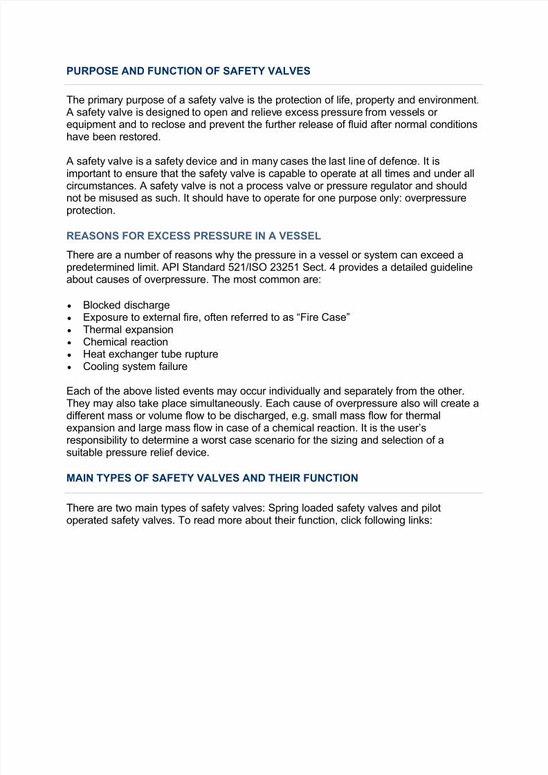
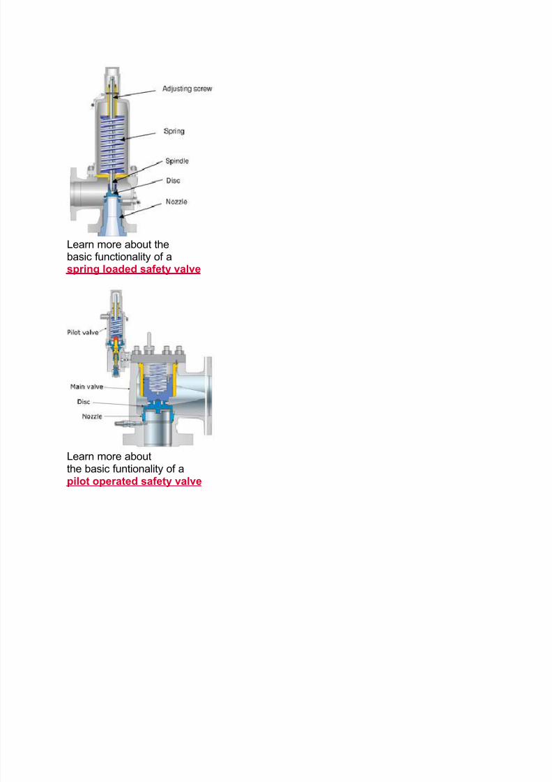
There are two main types of safety valves: Spring loaded safety valves and pilotoperated safety valves. To read more about their function, click following links:
7/27/2019 Pressure Safety Valve Fundamentals
http://slidepdf.com/reader/full/pressure-safety-valve-fundamentals 2/21
Learn more about thebasic functionality of a
spring loaded safety valve
Learn more aboutthe basic funtionality of apilot operated safety valve
7/27/2019 Pressure Safety Valve Fundamentals
http://slidepdf.com/reader/full/pressure-safety-valve-fundamentals 3/21
BASIC FUNCTION OF A SPRING LOADED SAFETY VALVE
VALVE CLOSED
In a direct spring loaded safety valve the closing force or spring force is applied by a
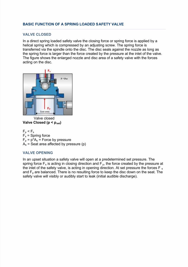
helical spring which is compressed by an adjusting screw. The spring force istransferred via the spindle onto the disc. The disc seals against the nozzle as long asthe spring force is larger than the force created by the pressure at the inlet of the valve.The figure shows the enlarged nozzle and disc area of a safety valve with the forcesacting on the disc.
Valve closedValve Closed (p < pset)
Fp < Fs Fs = Spring force
Fp = p*As = Force by pressure As = Seat area affected by pressure (p)
VALVE OPENING
In an upset situation a safety valve will open at a predetermined set pressure. Thespring force Fs is acting in closing direction and Fp, the force created by the pressure atthe inlet of the safety valve, is acting in opening direction. At set pressure the forces Fs and Fp are balanced. There is no resulting force to keep the disc down on the seat. Thesafety valve will visibly or audibly start to leak (initial audible discharge).
7/27/2019 Pressure Safety Valve Fundamentals
http://slidepdf.com/reader/full/pressure-safety-valve-fundamentals 4/21
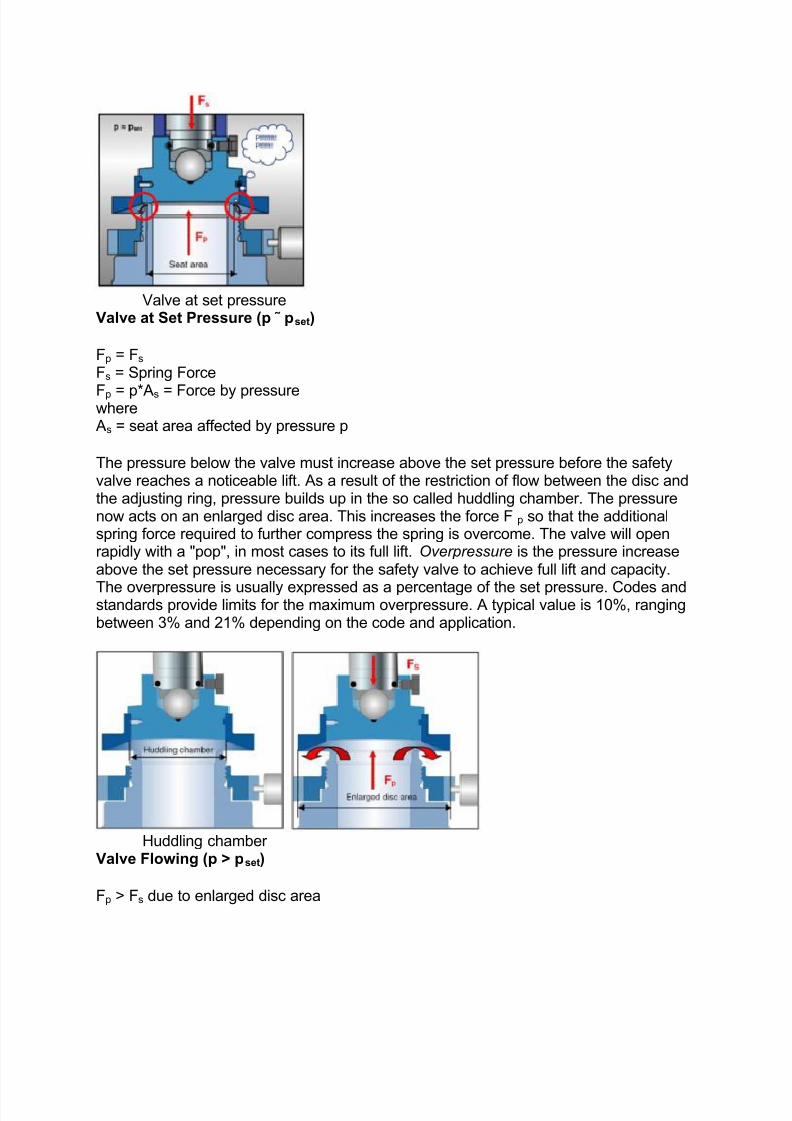
Valve at set pressure
Valve at Set Pressure (p ˜ pset)
Fp = Fs Fs = Spring Force
Fp = p*As = Force by pressurewhere
As = seat area affected by pressure p
The pressure below the valve must increase above the set pressure before the safetyvalve reaches a noticeable lift. As a result of the restriction of flow between the disc andthe adjusting ring, pressure builds up in the so called huddling chamber. The pressurenow acts on an enlarged disc area. This increases the force Fp so that the additionalspring force required to further compress the spring is overcome. The valve will openrapidly with a "pop", in most cases to its full lift. Overpressure is the pressure increaseabove the set pressure necessary for the safety valve to achieve full lift and capacity.
The overpressure is usually expressed as a percentage of the set pressure. Codes andstandards provide limits for the maximum overpressure. A typical value is 10%, rangingbetween 3% and 21% depending on the code and application.
Huddling chamber Valve Flowing (p > pset)
Fp > Fs due to enlarged disc area
7/27/2019 Pressure Safety Valve Fundamentals
http://slidepdf.com/reader/full/pressure-safety-valve-fundamentals 5/21
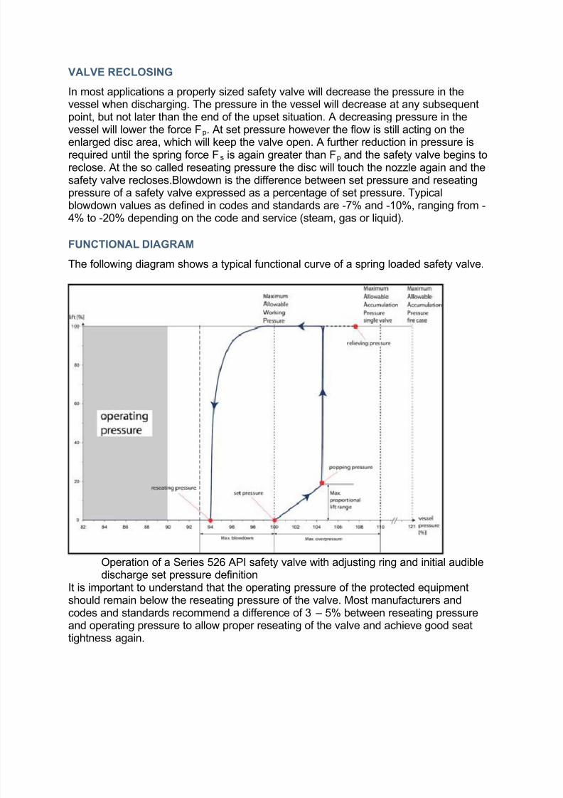
VALVE RECLOSING
In most applications a properly sized safety valve will decrease the pressure in thevessel when discharging. The pressure in the vessel will decrease at any subsequentpoint, but not later than the end of the upset situation. A decreasing pressure in thevessel will lower the force Fp. At set pressure however the flow is still acting on the
enlarged disc area, which will keep the valve open. A further reduction in pressure isrequired until the spring force Fs is again greater than Fp and the safety valve begins toreclose. At the so called reseating pressure the disc will touch the nozzle again and thesafety valve recloses.Blowdown is the difference between set pressure and reseatingpressure of a safety valve expressed as a percentage of set pressure. Typicalblowdown values as defined in codes and standards are -7% and -10%, ranging from -4% to -20% depending on the code and service (steam, gas or liquid).
FUNCTIONAL DIAGRAM
The following diagram shows a typical functional curve of a spring loaded safety valve.
Operation of a Series 526 API safety valve with adjusting ring and initial audibledischarge set pressure definition
It is important to understand that the operating pressure of the protected equipmentshould remain below the reseating pressure of the valve. Most manufacturers andcodes and standards recommend a difference of 3 – 5% between reseating pressureand operating pressure to allow proper reseating of the valve and achieve good seattightness again.
7/27/2019 Pressure Safety Valve Fundamentals
http://slidepdf.com/reader/full/pressure-safety-valve-fundamentals 6/21
There is a wide range of safety valves available to meet the many different applications
and performance criteria demanded by different industries. Furthermore, national
standards define many varying types of safety valve.
The ASME standard I and ASME standard VIII for boiler and pressure vessel
applications and the ASME / ANSI PTC 25.3 standard for safety valves and relief valves
provide the following definition. These standards set performance characteristics as well
as defining the different types of safety valves that are used:
ASME I valve - A safety relief valve conforming to the requirements of Section Iof the ASME pressure vessel code for boiler applications which will open within3% overpressure and close within 4%. It will usually feature two blowdown rings,and is identified by a National Board 'V' stamp.
ASME VIII valve - A safety relief valve conforming to the requirements of SectionVIII of the ASME pressure vessel code for pressure vessel applications which willopen within 10% overpressure and close within 7%. Identified by a NationalBoard 'UV' stamp.
Low lift safety valve - The actual position of the disc determines the dischargearea of the valve.
Full lift safety valve - The discharge area is not determined by the position of the disc.
Full bore safety valve - A safety valve having no protrusions in the bore, andwherein the valve lifts to an extent sufficient for the minimum area at any section,at or below the seat, to become the controlling orifice.
Conventional safety relief valve - The spring housing is vented to thedischarge side, hence operational characteristics are directly affected bychanges in the backpressure to the valve.
Balanced safety relief valve - A balanced valve incorporates a means of minimising the effect of backpressure on the operational characteristics of thevalve.
Pilot operated pressure relief valve - The major relieving device is combinedwith, and is controlled by, a self-actuated auxiliary pressure relief device.
Power-actuated safety relief valve - A pressure relief valve in which the major pressure relieving device is combined with, and controlled by, a device requiringan external source of energy.
The following types of safety valve are defined in the DIN 3320 standard, which relates
to safety valves sold in Germany and other parts of Europe:
Standard safety valve - A valve which, following opening, reaches the degree of lift necessary for the mass flowrate to be discharged within a pressure rise of notmore than 10%. (The valve is characterised by a pop type action and issometimes known as high lift).
7/27/2019 Pressure Safety Valve Fundamentals
http://slidepdf.com/reader/full/pressure-safety-valve-fundamentals 7/21
Full lift (Vollhub) safety valve - A safety valve which, after commencement of lift, opens rapidly within a 5% pressure rise up to the full lift as limited by thedesign. The amount of lift up to the rapid opening (proportional range) shall notbe more than 20%.
Direct loaded safety valve - A safety valve in which the opening force
underneath the valve disc is opposed by a closing force such as a spring or aweight. Proportional safety valve - A safety valve which opens more or less steadily in
relation to the increase in pressure. Sudden opening within a 10% lift range willnot occur without pressure increase. Following opening within a pressure of notmore than 10%, these safety valves achieve the lift necessary for the mass flowto be discharged.
Diaphragm safety valve - A direct loaded safety valve wherein linear movingand rotating elements and springs are protected against the effects of the fluid bya diaphragm.
Bellows safety valve - A direct loaded safety valve wherein sliding and (partially
or fully) rotating elements and springs are protected against the effects of thefluids by a bellows. The bellows may be of such a design that it compensates for influences of backpressure.
Controlled safety valve - Consists of a main valve and a control device. It alsoincludes direct acting safety valves with supplementary loading in which, until theset pressure is reached, an additional force increases the closing force.
EN ISO 4126 lists the following definitions of types of safety valve:
Safety valve - A safety valve which automatically, without the assistance of anyenergy other than that of the fluid concerned, discharges a quantity of the fluid so
as to prevent a predetermined safe pressure being exceeded, and which isdesigned to re-close and prevent further flow of fluid after normal pressureconditions of service have been restored. Note; the valve can be characterisedeither by pop action (rapid opening) or by opening in proportion (not necessarilylinear) to the increase in pressure over the set pressure.
Direct loaded safety valve - A safety valve in which the loading due to the fluidpressure underneath the valve disc is opposed only by a direct mechanicalloading device such as a weight, lever and weight, or a spring.
Assisted safety valve - A safety valve which by means of a powered assistancemechanism, may additionally be lifted at a pressure lower than the set pressureand will, even in the event of a failure of the assistance mechanism, comply with
all the requirements for safety valves given in the standard. Supplementary loaded safety valve - A safety valve that has, until the pressure
at the inlet to the safety valve reaches the set pressure, an additional force,which increases the sealing force. Note; this additional force (supplementaryload), which may be provided by means of an extraneous power source, isreliably released when the pressure at the inlet of the safety valve reaches theset pressure. The amount of supplementary loading is so arranged that if suchsupplementary loading is not released, the safety valve will attain its certified
7/27/2019 Pressure Safety Valve Fundamentals
http://slidepdf.com/reader/full/pressure-safety-valve-fundamentals 8/21
discharge capacity at a pressure not greater than 1.1 times the maximumallowable pressure of the equipment to be protected.
Pilot operated safety valve - A safety valve, the operation of which is initiatedand controlled by the fluid discharged from a pilot valve, which is itself, a directloaded safety valve subject to the requirement of the standard.
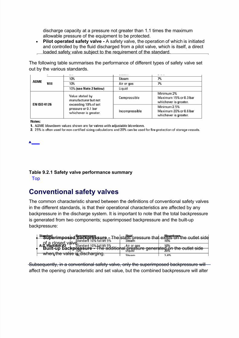
The following table summarises the performance of different types of safety valve set
out by the various standards.
Table 9.2.1 Safety valve performance summary
Top
Conventional safety valves
The common characteristic shared between the definitions of conventional safety valves
in the different standards, is that their operational characteristics are affected by any
backpressure in the discharge system. It is important to note that the total backpressure
is generated from two components; superimposed backpressure and the built-up
backpressure:
Superimposed backpressure - The static pressure that exists on the outlet sideof a closed valve.
Built-up backpressure - The additional pressure generated on the outlet sidewhen the valve is discharging.
Subsequently, in a conventional safety valve, only the superimposed backpressure will
affect the opening characteristic and set value, but the combined backpressure will alter

7/27/2019 Pressure Safety Valve Fundamentals
http://slidepdf.com/reader/full/pressure-safety-valve-fundamentals 9/21
the blowdown characteristic and re-seat value.
The ASME/ANSI standard makes the further classification that conventional valves
have a spring housing that is vented to the discharge side of the valve. If the spring
housing is vented to the atmosphere, any superimposed backpressure will still affect the
operational characteristics. This can be seen from Figure 9.2.1, which shows schematic
diagrams of valves whose spring housings are vented to the discharge side of the valve
and to the atmosphere.
Fig.
9.2.1 Schematic diagram of safety valves with bonnets vented to (a) the valve
discharge and (b) the atmosphere
By considering the forces acting on the disc (with area AD), it can be seen that the
required opening force (equivalent to the product of inlet pressure (PV) and the nozzlearea (AN)) is the sum of the spring force (FS) and the force due to the backpressure
(PB) acting on the top and bottom of the disc. In the case of a spring housing vented to
the discharge side of the valve (an ASME conventional safety relief valve, see Figure
9.2.1 (a)), the required opening force is:
Equation 9.2.1
Where:
PV = Fluid inlet pressure
AN = Nozzle area
FS = Spring force
7/27/2019 Pressure Safety Valve Fundamentals
http://slidepdf.com/reader/full/pressure-safety-valve-fundamentals 10/21
PB = Backpressure
Therefore, any superimposed backpressure will tend to increase the closing force and
the inlet pressure required to lift the disc is greater.
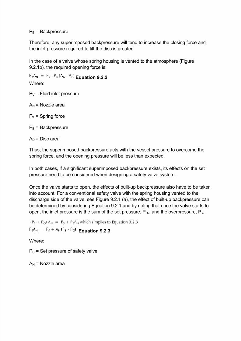
In the case of a valve whose spring housing is vented to the atmosphere (Figure
9.2.1b), the required opening force is:
Equation 9.2.2
Where:
PV = Fluid inlet pressure
AN = Nozzle area
FS = Spring force
PB = Backpressure
AD = Disc area
Thus, the superimposed backpressure acts with the vessel pressure to overcome the
spring force, and the opening pressure will be less than expected.
In both cases, if a significant superimposed backpressure exists, its effects on the set
pressure need to be considered when designing a safety valve system.
Once the valve starts to open, the effects of built-up backpressure also have to be taken
into account. For a conventional safety valve with the spring housing vented to the
discharge side of the valve, see Figure 9.2.1 (a), the effect of built-up backpressure can
be determined by considering Equation 9.2.1 and by noting that once the valve starts to
open, the inlet pressure is the sum of the set pressure, P S, and the overpressure, PO.
Equation 9.2.3
Where:
PS = Set pressure of safety valve
AN = Nozzle area
7/27/2019 Pressure Safety Valve Fundamentals
http://slidepdf.com/reader/full/pressure-safety-valve-fundamentals 11/21
FS = Spring force
PB = Backpressure
PO = Overpressure
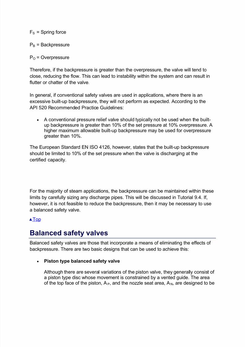
Therefore, if the backpressure is greater than the overpressure, the valve will tend to
close, reducing the flow. This can lead to instability within the system and can result in
flutter or chatter of the valve.
In general, if conventional safety valves are used in applications, where there is an
excessive built-up backpressure, they will not perform as expected. According to the
API 520 Recommended Practice Guidelines:
A conventional pressure relief valve should typically not be used when the built-up backpressure is greater than 10% of the set pressure at 10% overpressure. Ahigher maximum allowable built-up backpressure may be used for overpressuregreater than 10%.
The European Standard EN ISO 4126, however, states that the built-up backpressure
should be limited to 10% of the set pressure when the valve is discharging at the
certified capacity.
For the majority of steam applications, the backpressure can be maintained within these
limits by carefully sizing any discharge pipes. This will be discussed in Tutorial 9.4. If,
however, it is not feasible to reduce the backpressure, then it may be necessary to use
a balanced safety valve.
Top
Balanced safety valves
Balanced safety valves are those that incorporate a means of eliminating the effects of backpressure. There are two basic designs that can be used to achieve this:
Piston type balanced safety valve
Although there are several variations of the piston valve, they generally consist of a piston type disc whose movement is constrained by a vented guide. The areaof the top face of the piston, AP, and the nozzle seat area, AN, are designed to be
7/27/2019 Pressure Safety Valve Fundamentals
http://slidepdf.com/reader/full/pressure-safety-valve-fundamentals 12/21
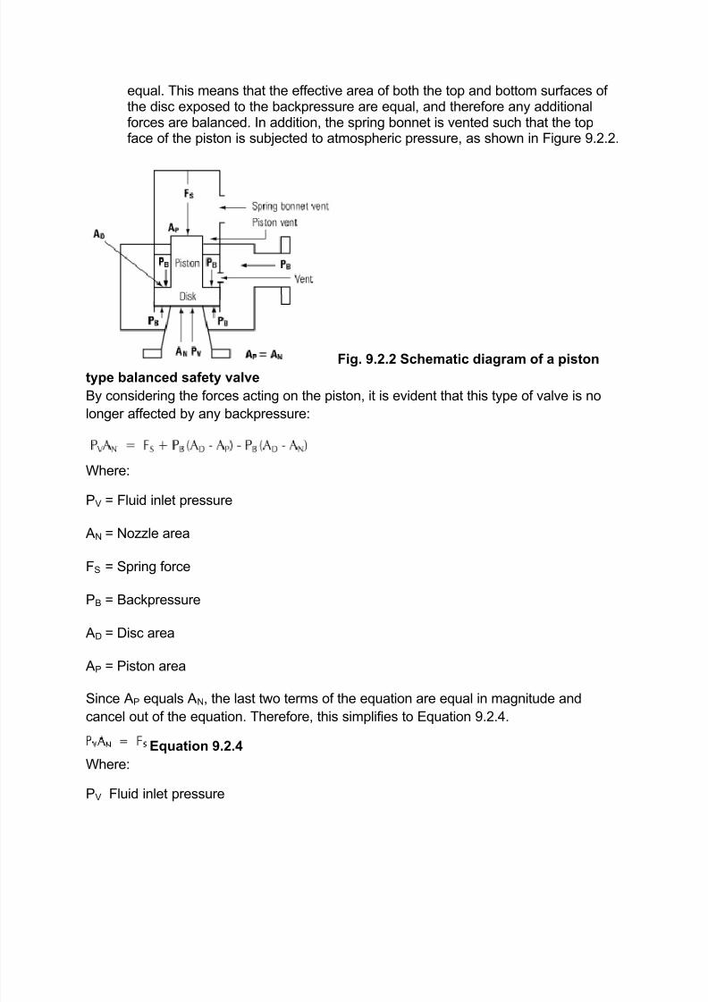
equal. This means that the effective area of both the top and bottom surfaces of the disc exposed to the backpressure are equal, and therefore any additionalforces are balanced. In addition, the spring bonnet is vented such that the topface of the piston is subjected to atmospheric pressure, as shown in Figure 9.2.2.
Fig. 9.2.2 Schematic diagram of a piston
type balanced safety valve
By considering the forces acting on the piston, it is evident that this type of valve is no
longer affected by any backpressure:
Where:
PV = Fluid inlet pressure
AN = Nozzle area
FS = Spring force
PB = Backpressure
AD = Disc area
AP = Piston area
Since AP equals AN, the last two terms of the equation are equal in magnitude andcancel out of the equation. Therefore, this simplifies to Equation 9.2.4.
Equation 9.2.4
Where:
PV Fluid inlet pressure
7/27/2019 Pressure Safety Valve Fundamentals
http://slidepdf.com/reader/full/pressure-safety-valve-fundamentals 13/21
AN Nozzle area
FS Spring force
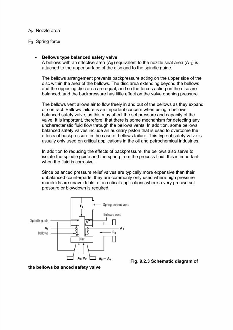
Bellows type balanced safety valve A bellows with an effective area (AB) equivalent to the nozzle seat area (AN) isattached to the upper surface of the disc and to the spindle guide.
The bellows arrangement prevents backpressure acting on the upper side of thedisc within the area of the bellows. The disc area extending beyond the bellowsand the opposing disc area are equal, and so the forces acting on the disc arebalanced, and the backpressure has little effect on the valve opening pressure.
The bellows vent allows air to flow freely in and out of the bellows as they expandor contract. Bellows failure is an important concern when using a bellows
balanced safety valve, as this may affect the set pressure and capacity of thevalve. It is important, therefore, that there is some mechanism for detecting anyuncharacteristic fluid flow through the bellows vents. In addition, some bellowsbalanced safety valves include an auxiliary piston that is used to overcome theeffects of backpressure in the case of bellows failure. This type of safety valve isusually only used on critical applications in the oil and petrochemical industries.
In addition to reducing the effects of backpressure, the bellows also serve toisolate the spindle guide and the spring from the process fluid, this is importantwhen the fluid is corrosive.
Since balanced pressure relief valves are typically more expensive than their unbalanced counterparts, they are commonly only used where high pressuremanifolds are unavoidable, or in critical applications where a very precise setpressure or blowdown is required.
Fig. 9.2.3 Schematic diagram of
the bellows balanced safety valve
7/27/2019 Pressure Safety Valve Fundamentals
http://slidepdf.com/reader/full/pressure-safety-valve-fundamentals 14/21
Top
Pilot operated safety valve
This type of safety valve uses the flowing medium itself, through a pilot valve, to apply
the closing force on the safety valve disc. The pilot valve is itself a small safety valve.
There are two basic types of pilot operated safety valve, namely, the diaphragm and
piston type.
The diaphragm type is typically only available for low pressure applications and it
produces a proportional type action, characteristic of relief valves used in liquid
systems. They are therefore of little use in steam systems, consequently, they will not
be considered in this text.
The piston type valve consists of a main valve, which uses a piston shaped closing
device (or obturator), and an external pilot valve. Figure 9.2.4 shows a diagram of a
typical piston type, pilot operated safety valve.
7/27/2019 Pressure Safety Valve Fundamentals
http://slidepdf.com/reader/full/pressure-safety-valve-fundamentals 15/21
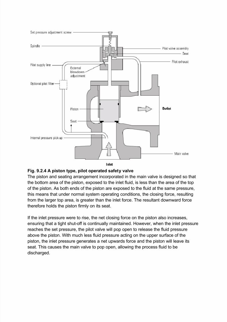
Fig. 9.2.4 A piston type, pilot operated safety valve
The piston and seating arrangement incorporated in the main valve is designed so that
the bottom area of the piston, exposed to the inlet fluid, is less than the area of the top
of the piston. As both ends of the piston are exposed to the fluid at the same pressure,
this means that under normal system operating conditions, the closing force, resulting
from the larger top area, is greater than the inlet force. The resultant downward force
therefore holds the piston firmly on its seat.
If the inlet pressure were to rise, the net closing force on the piston also increases,
ensuring that a tight shut-off is continually maintained. However, when the inlet pressurereaches the set pressure, the pilot valve will pop open to release the fluid pressure
above the piston. With much less fluid pressure acting on the upper surface of the
piston, the inlet pressure generates a net upwards force and the piston will leave its
seat. This causes the main valve to pop open, allowing the process fluid to be
discharged.
7/27/2019 Pressure Safety Valve Fundamentals
http://slidepdf.com/reader/full/pressure-safety-valve-fundamentals 16/21
When the inlet pressure has been sufficiently reduced, the pilot valve will reclose,
preventing the further release of fluid from the top of the piston, thereby re-establishing
the net downward force, and causing the piston to reseat.
Pilot operated safety valves offer good overpressure and blowdown performance (a
blowdown of 2% is attainable). For this reason, they are used where a narrow margin is
required between the set pressure and the system operating pressure. Pilot operated
valves are also available in much larger sizes, making them the preferred type of safety
valve for larger capacities.
One of the main concerns with pilot operated safety valves is that the small bore, pilot
connecting pipes are susceptible to blockage by foreign matter, or due to the collection
of condensate in these pipes. This can lead to the failure of the valve, either in the open
or closed position, depending on where the blockage occurs.
Top
Full lift, high lift and low lift safety valves
The terms full lift, high lift and low lift refer to the amount of travel the disc undergoes as
it moves from its closed position to the position required to produce the certified
discharge capacity, and how this affects the discharge capacity of the valve.
A full lift safety valve is one in which the disc lifts sufficiently, so that the curtain area no
longer influences the discharge area. The discharge area, and therefore the capacity of
the valve are subsequently determined by the bore area. This occurs when the disc liftsa distance of at least a quarter of the bore diameter. A full lift conventional safety valve
is often the best choice for general steam applications.
The disc of a high lift safety valve lifts a distance of at least1/12th of the bore diameter.
This means that the curtain area, and ultimately the position of the disc, determines the
discharge area. The discharge capacities of high lift valves tend to be significantly lower
than those of full lift valves, and for a given discharge capacity, it is usually possible to
select a full lift valve that has a nominal size several times smaller than a corresponding
high lift valve, which usually incurs cost advantages. Furthermore, high lift valves tend
to be used on compressible fluids where their action is more proportional.
In low lift valves, the disc only lifts a distance of 1/24th of the bore diameter. The
discharge area is determined entirely by the position of the disc, and since the disc only
lifts a small amount, the capacities tend to be much lower than those of full or high lift
valves.
7/27/2019 Pressure Safety Valve Fundamentals
http://slidepdf.com/reader/full/pressure-safety-valve-fundamentals 17/21
Top
Materials of construction
Except when safety valves are discharging, the only parts that are wetted by the
process fluid are the inlet tract (nozzle) and the disc. Since safety valves operate
infrequently under normal conditions, all other components can be manufactured from
standard materials for most applications. There are however several exceptions, in
which case, special materials have to be used, these include:
Cryogenic applications. Corrosive fluids. Where contamination of discharged fluid is not permitted. When the valve discharges into a manifold that contains corrosive media
discharged by another valve.
The principal pressure-containing components of safety valves are normally constructedfrom one of the following materials:
Bronze - Commonly used for small screwed valves for general duty on steam, air and hot water applications (up to 15 bar).
Cast iron - Used extensively for ASME type valves. Its use is typically limited to17 bar g.
SG iron - Commonly used in European valves and to replace cast iron in higher pressure valves (up to 25 bar g).
Cast steel - Commonly used on higher pressure valves (up to 40 bar g). Processtype valves are usually made from a cast steel body with an austenitic full nozzletype construction.
Austenitic stainless steel - Used in food, pharmaceutical or clean steamapplications.
For extremely high pressure applications, pressure containing components may be
forged or machined from solid.
For all safety valves, it is important that moving parts, particularly the spindle and guides
are made from materials that will not easily degrade or corrode. As seats and discs are
constantly in contact with the process fluid, they must be able to resist the effects of
erosion and corrosion. For process applications, austenitic stainless steel is commonlyused for seats and discs; sometimes they are 'stellite faced' for increased durability. For
extremely corrosive fluids, nozzles, discs and seats are made from special alloys such
as 'monel' or 'hastelloy'.
The spring is a critical element of the safety valve and must provide reliable
performance within the required parameters. Standard safety valves will typically use
7/27/2019 Pressure Safety Valve Fundamentals
http://slidepdf.com/reader/full/pressure-safety-valve-fundamentals 18/21
carbon steel for moderate temperatures. Tungsten steel is used for higher temperature,
non-corrosive applications, and stainless steel is used for corrosive or clean steam duty.
For sour gas and high temperature applications, often special materials such as monel,
hastelloy and 'inconel' are used.
Top
Safety valve options and accessories
Due to the wide range of applications in which safety valves are used, there are a
number of different options available:
Seating material
A key option is the type of seating material used. Metal-to-metal seats, commonly made
from stainless steel, are normally used for high temperature applications such as steam.
Alternatively, resilient discs can be fixed to either or both of the seating surfaces where
tighter shut-off is required, typically for gas or liquid applications. These inserts can bemade from a number of different materials, but Viton, nitrile or EPDM are the most
common. Soft seal inserts are not generally recommended for steam use.
Table 9.2.2 Seating materials used in safety valves
Levers
Standard safety valves are generally fitted with an easing lever, which enables the valve
to be lifted manually in order to ensure that it is operational at pressures in excess of
75% of set pressure. This is usually done as part of routine safety checks, or during
maintenance to prevent seizing. The fitting of a lever is usually a requirement of national
standards and insurance companies for steam and hot water applications. For example,
the ASME Boiler and Pressure Vessel Code states that pressure relief valves must be
fitted with a lever if they are to be used on air, water over 60°C, and steam.
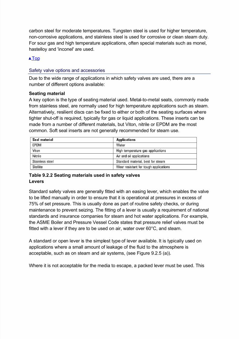
A standard or open lever is the simplest type of lever available. It is typically used on
applications where a small amount of leakage of the fluid to the atmosphere is
acceptable, such as on steam and air systems, (see Figure 9.2.5 (a)).
Where it is not acceptable for the media to escape, a packed lever must be used. This
7/27/2019 Pressure Safety Valve Fundamentals
http://slidepdf.com/reader/full/pressure-safety-valve-fundamentals 19/21
uses a packed gland seal to ensure that the fluid is contained within the cap, (see
Figure 9.2.5 (b))
Fig. 9.2.5 Levers
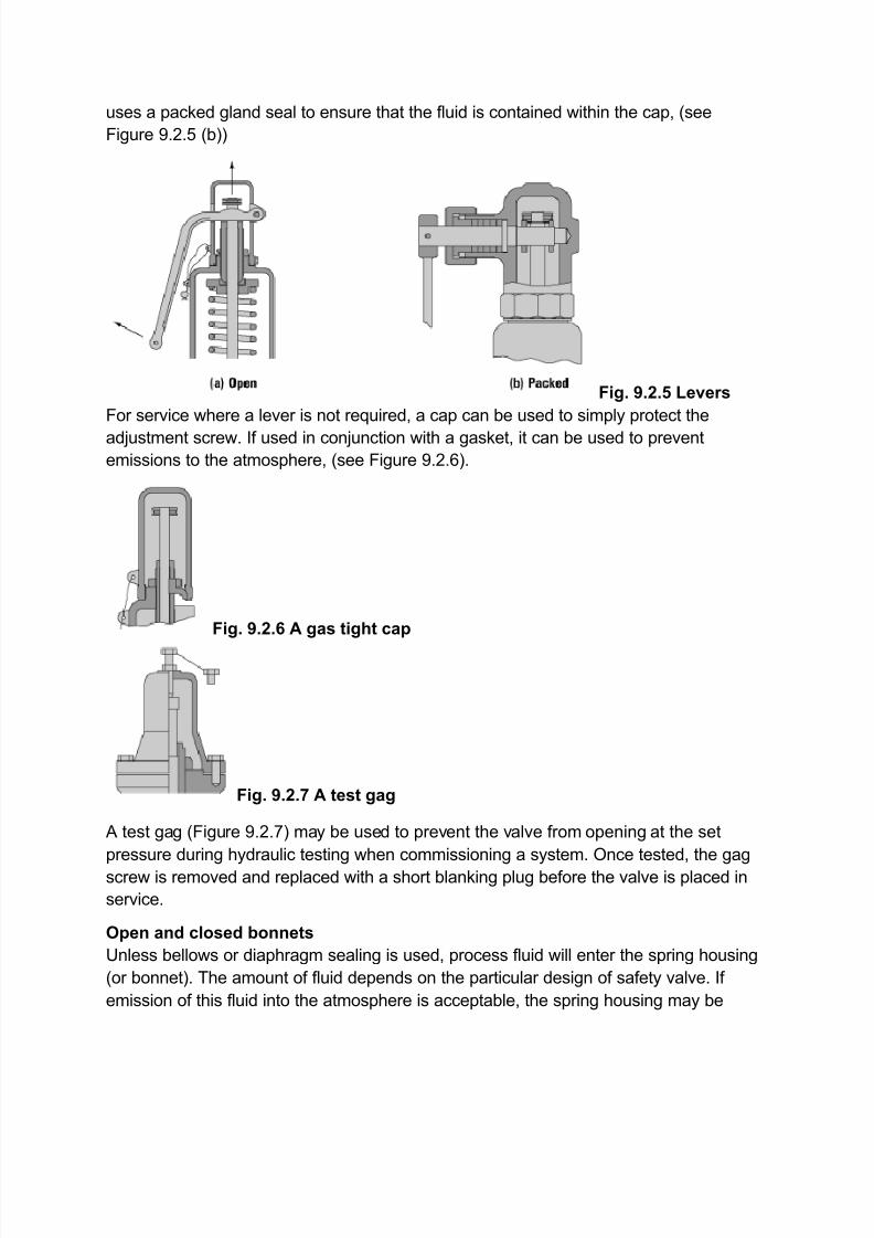
For service where a lever is not required, a cap can be used to simply protect the
adjustment screw. If used in conjunction with a gasket, it can be used to preventemissions to the atmosphere, (see Figure 9.2.6).
Fig. 9.2.6 A gas tight cap
Fig. 9.2.7 A test gag
A test gag (Figure 9.2.7) may be used to prevent the valve from opening at the set
pressure during hydraulic testing when commissioning a system. Once tested, the gag
screw is removed and replaced with a short blanking plug before the valve is placed in
service.
Open and closed bonnets
Unless bellows or diaphragm sealing is used, process fluid will enter the spring housing
(or bonnet). The amount of fluid depends on the particular design of safety valve. If
emission of this fluid into the atmosphere is acceptable, the spring housing may be
7/27/2019 Pressure Safety Valve Fundamentals
http://slidepdf.com/reader/full/pressure-safety-valve-fundamentals 20/21
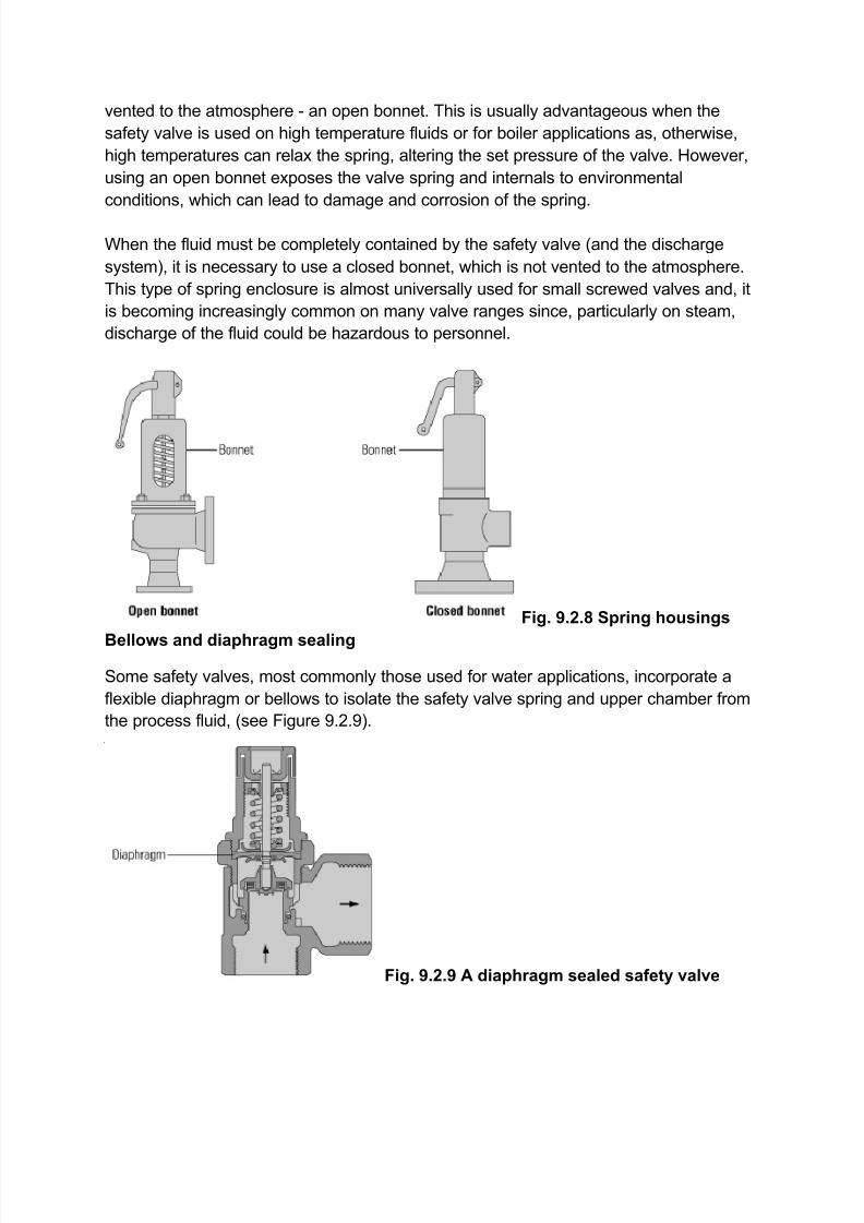
vented to the atmosphere - an open bonnet. This is usually advantageous when the
safety valve is used on high temperature fluids or for boiler applications as, otherwise,
high temperatures can relax the spring, altering the set pressure of the valve. However,
using an open bonnet exposes the valve spring and internals to environmental
conditions, which can lead to damage and corrosion of the spring.
When the fluid must be completely contained by the safety valve (and the discharge
system), it is necessary to use a closed bonnet, which is not vented to the atmosphere.
This type of spring enclosure is almost universally used for small screwed valves and, it
is becoming increasingly common on many valve ranges since, particularly on steam,
discharge of the fluid could be hazardous to personnel.
Fig. 9.2.8 Spring housings
Bellows and diaphragm sealing
Some safety valves, most commonly those used for water applications, incorporate a
flexible diaphragm or bellows to isolate the safety valve spring and upper chamber from
the process fluid, (see Figure 9.2.9).
Fig. 9.2.9 A diaphragm sealed safety valve

7/27/2019 Pressure Safety Valve Fundamentals
http://slidepdf.com/reader/full/pressure-safety-valve-fundamentals 21/21
An elastomer bellows or diaphragm is commonly used in hot water or heating
applications, whereas a stainless steel one would be used on process applications
employing hazardous fluids.