Embed Size (px)
Citation preview
Pressure relief valves
Wandfluh AG Tel. +41 33 672 72 72 E-mail: [email protected] Illustrations not obligatory Data sheet no.Postfach Fax +41 33 672 72 12 Internet: www.wandfluh.com Data subject to change 2.1-520E 1/2 CH-3714 Frutigen Edition 10 19
APPLICATIONFor limiting the operating pressure in hydraulic systems by releasing the oil from the protec-ted oil line P (1) to the outlet/tank return line T (2). The screw-in cartridge is very suitable for mounting in control blocks and is built into the Wandfluh miniature hydraulics NG3 as a functional element in sandwich style plates (vertical combination) and flange-mounted valves (please refer to the separate data sheets in register 2.1). Stepped tools are available for making the receptacle bores in steel and aluminium (Hire or purchase). Please refer to the data sheets in register 2.13.Attention: Should therefore not be utilized any-more in applications with periodically changing direction of flow.
FUNCTIONWhen the set operating pressure is reached, the poppet spool opens and connects the pro-tected line with the return line to the tank. By means of the adjusting mechanism the poppet spool is pressed onto a hardened seat which is pressed into the lower cartridge opening by a helical spring. Thanks to the poppet/spool principle and the direct operation, these pres-sure reliefe valves are rapid acting and free fo leakage oil. Therefore they are suitable where-ver no leakage must occur in the system and where short opening times are demanded.
Pressure relief valveScrew-in cartridge• Direct operated• Qmax = 5 l/min• pmax = 400 bar• pN max = 315 bar
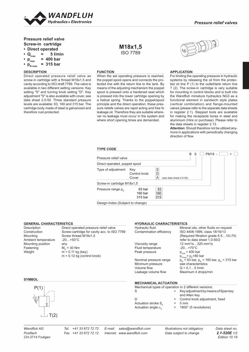
SYMBOL
DESCRIPTIONDirect operated pressure relief valve as screw-in cartridge with a thread M18x1,5 and cavity according to ISO draft 7789. The valve is available in two different setting versions: Key setting "S" and turning knob setting "D". Key adjustment "S" is also available with cover, see data sheet 2.0-50. Three standard pressure levels are available: 63, 160 and 315 bar. The cartridge body made of steel is galvanized and therefore rust-protected.
TYPE CODE B S PM18 - #Pressure relief valve
Direct operated, poppet spool
Type of adjustment Key S Control knob D Cover A (see data sheet 2.0-50)
Screw-in cartridge M18x1,5
Pressure range pN 63 bar 63 160 bar 160 315 bar 315
Design-Index (Subject to change)
GENERAL CHARACTERISTICSDescription Direct operated pressure relief valveConstruction Screw-cartridge for cavity acc. to ISO 7789Mounting Screw thread M18x1,5 Ambient temperature -20…+50°CMounting position anyFastening MD = 30 NmWeight m = 0,11 kg (key) m = 0,12 kg (control knob)
HYDRAULIC CHARACTERISTICSHydraulic fluid Mineral oils, other fluids on requestContamination efficiency ISO 4406:1999, class 18/16/13 (Required filtration grade ß 6…10≥75) refer to data sheet 1.0-50/2Viscosity range 12 mm2/s…320 mm2/sFluid temperature -20…+70°CPeak pressure pmax = 400 bar pTmax= pP+80 barNominal pressure range pN = 63 bar, pN = 160 bar, pN = 315 barMinimum pressure see characteristicsVolume flow Q = 0,1…5 l/minLeakage volume flow Maximum 4 drops/min
MECHANICAL ACTUATIONMechanical types of operation in 2 different versions:S = Key adjustment by means of Span key and Allen keyD = Control knob adjustment, fixedActuation stroke Sb = 5 mmActuation angle αb = 1800° (5 revolutions)
M18x1,5ISO 7789
30
17Ø
44,6
26Ø
52
s13
s19
ø23
M18x1,5
s4 3020
40
50
60
70
P(1)
T(2)
Pressure relief valves
Wandfluh AG Tel. +41 33 672 72 72 E-mail: [email protected] Illustrations not obligatory Data sheet no.Postfach Fax +41 33 672 72 12 Internet: www.wandfluh.com Data subject to change 2.1-520E 2/2 CH-3714 Frutigen Edition 10 19
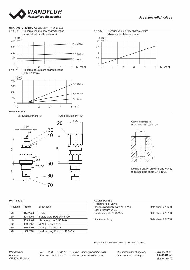
DIMENSIONS
p = f (n) Pressure adjustment characteristics (at Q = 1 l/min)
Detailed cavity drawing and cavity tools see data sheet 2.13-1001.
Cavity drawing to ISO 7789–18–02–0–98
CHARACTERISTICS Oil viscosity υ = 30 mm2/sp = f (Q) Pressure volume flow characteristics p = f (Q) Pressure volume flow characteristics (Maximal adjustable pressure) (Minimal adjustable pressure)
Screw adjustment "S" Knob adjustment "D"
Technical explanation see data sheet 1.0-100
PARTS LIST
Position Article Discription
20 114.2224 Knob30 193.1061 Safety plate RD6 DIN 679940 153.1402 Hexagonal nut 0,5D M8x150 160.2156 O-ring ID 15,6x1,7860 160.2093 O-ring ID 9,25x1,7870 49.3137 Back-up ring RD 10,6x13,5x1,4
(2)
(1)
M18x1,5
(1)
ACCESSORIESPressure relief valve:Flange-/sandwich plate NG3-Mini Data sheet 2.1-600Back pressure valve:Sandwich plate NG3-Mini Data sheet 2.1-700
Line mount body Data sheet 2.9-200
p [bar]K0113_1
n [-]
PN = 315 bar
PN = 160 bar
PN = 63 bar
400
300
200
100
00 1 2 3 4 5
0 1 2 3 4 5 Q [l/min]
K0672
p [bar]400
30 300
200
100
0
PN = 315 bar
PN = 160 bar
PN = 63 bar
0 1 2 3 4 5 Q [l/min]
K0673
p [bar]10
7,5
5
2,5
0
30
17Ø
44,6
26Ø
52
s13
s19
ø23
M18x1,5
s4 3020
40
50
60
70
P(1)
T(2)