Embed Size (px)
Citation preview

10th International Research/Expert Conference ”Trends in the Development of Machinery and Associated Technology”
TMT 2006, Barcelona-Lloret de Mar, Spain, 11-15 September, 2006
PRESSURE REGULATORS APPLIED TO FORCE/POSITION CONTROL OF A PNEUMATIC ACTUATOR
Željko Šitum, Tihomir Žilić, Mario Essert Faculty of Mechanical Engineering and Naval Architecture
University of Zagreb I. Lučića 5, 10000 Zagreb
Croatia
ABSTRACT Proportional pressure regulators are usually used in different automation processes where continuous pressure or force control is required. They originated from the combination of an electro-pneumatic pilot valve, pressure regulator and pressure sensor for achieving an internal pressure feedback. These valves have practically linear pressure output regarding to an electrical signal from a control device. By controlling pressures in both cylinder chambers they can be used for direct force control of a pneumatic system. However, in this paper, also the position control of a pneumatic actuator using two proportional pressure regulators has been considered. A simplified dynamic model of the process has been derived, followed by a design of the PD controller for the system control. The control algorithms are experimentally verified on an industrial pneumatic cylinder controlled by two proportional pressure valves. The results demonstrate that the proportional pressure valves have a potential for successful implementation in hybrid force/position control tasks. Keywords: pneumatic system control, proportional pressure valve 1. INTRODUCTION Pneumatic driving systems are usually used in manufacturing process where it is necessary to achieve a device that is inexpensive, clean, reliable, and simple for realization. They have found widespread application in the field of industrial automation for pick-and-place positioning problems. However, for free positioning tasks, pneumatic drives are difficult to control accurately, because of nonlinearities associated with the compressibility of the air, significant friction effects and variations of system parameters. Therefore, over the years, for the flexible positioning operations some other motion technologies mainly based on costly electromechanical systems for lighter loads and hydraulic drives for heavy loads have been used. However, the development of the proportional directional control pneumatic valves in the last two decades is created pneumatic servo-technology. Despite the problems in controlling pneumatically powered drives, they offer in many cases competitive cost/performance characteristics. With proportional valves a continuous feedback control can be obtained and thus the flexible, fast and precise positioning tasks of pneumatic actuators have made possible. As a result, a large amount of research work has been made in which the pneumatic drives are successfully used for position-control application using different control techniques, including the works [1-3], among others. In most of them relatively expensive proportional servo valve is used, which however, gives the best results. Using some adequate control algorithms such as pulse-width modulation (PWM) techniques enable low-cost on/off solenoid valves to be used as an admissible substitute for costly proportional valves in pneumatic servo applications [4, 5]. In this paper instead of proportional directional control valve two electronic pressure valves have been implemented. They become as a combination of electro-pneumatic pilot valves, pressure regulators and pressure sensors for achieving an internal pressure feedback. An amplifier is built in the valve and an easy electrical connection with control device is possible. They have a multi-step or linear pressure
1047

output regarding to electrical command signal from a control device. A change of command signal produces a change of valve pressure output, i.e. pressure in cylinder chamber. These valves are usually used in different automation process where continuous pressure control is required (for example tank pressure control, control of cylinder force, tension control, nozzle flow control, etc.). However, by controlling pressure in cylinder chambers and achieving an external position feedback, these valves can also be used for the purpose of realization an electro-pneumatic position servo drive [6, 7]. With such characteristics proportional pressure valves have a potential for hybrid force/position control applications. 2. DYNAMIC MODEL OF THE PROCESS In order to obtain a simplified mathematical model in the form of transfer function, which gives relation between position of the piston x and command signal u on proportional pressure valve, first will be derived the relation between position of the piston and pressure in the chamber, and then the relation between pressure in the chamber and control signal. a) Relation between piston position and pressure in the cylinder chamber Applying the equations for the forces on the piston yields the dynamic behavior of piston motion: … (1) xkApxm &&& f−Δ=where is the air pressure difference in the cylinder chambers, m is overall load and the piston mass, A is the area of the piston, k
BA ppp −=Δ
f is the viscosity friction coefficient, x is the piston position. The transfer function as the ratio of the piston position and pressure difference in the cylinder chamber obtained from Laplace transform of the differential equation (1) can be written:
)()(
)()(f
1 ksmsA
spsxsG
+=
Δ= . … (2)
b) Relation between pressure in cylinder chamber and control signal The transfer function as the ratio of the chamber pressure and control signal on the valve is obtained from experimentally measured pressure response on step command input shown in Figure 1. Measured output up is the voltage on the pressure sensor.
)(V
u p
Figure 1. Pressure transient response
0 1 2 3 4 5 6-0.1
0
0.1
0.2
0.3
0.4
0.5
0.6
)(Vu
)(M
Pap
Figure 2. Static characteristic of the process
The pressure transient-response can be approximated with first order dynamic member (PT1 transfer function) as follows:
1)(
)()(p
p2 +
=Δ
=sT
KsuspsG … (3)
where Kp (MPa/V) is the transfer gain, Tp is the time constant of the process, which can be approximated on value Tp≈0.12 s. The forward gain Kp is obtained from experimentally measured static characteristic of the process, shown in Figure 2. The characteristic is obtained by measuring voltage on the pressure sensor for varying command signal (from 0 V to 5 V and then from 5 V to 0 V with step of 0.01 V). It can be seen the hysteresis on static characteristic and nonlinearity on both side
1048
of the characteristic. For control voltage signal larger then about 3.2 V the characteristic enters into saturation caused by limited supply pressure p0 ≈ 0.52 MPa. Because of that the area of usefulness voltage signal (linear part of static characteristic) during the system control will be in the range of approximately 1.1-3.2 V. The forward gain can be derived as a change of sensor voltage up for a change of control voltage on the valve u and on linear part of the static characteristic can be approximated as:
)V/V(85.0)(p
p ≅Δ
Δ=′
uuu
K … (4)
or as a change of cylinder pressure p for a change of control voltage u and on linear part of the static characteristic can be approximated as:
)MPa/V(22.0)(p ≅
ΔΔ
=uupK . … (5)
c) Transfer function of the process: relation between piston position and control signal Considering the piston position as the output and the applied control voltage from the control device, the transfer function of the process is obtained as a combination of transfer functions (2) and (3):
)1)(()(
)()()(
)()()()()(
pf
p21 ++
⋅==
Δ⋅
Δ=⋅=
sTksmsKA
susx
susp
spsxsGsGsG . … (6)
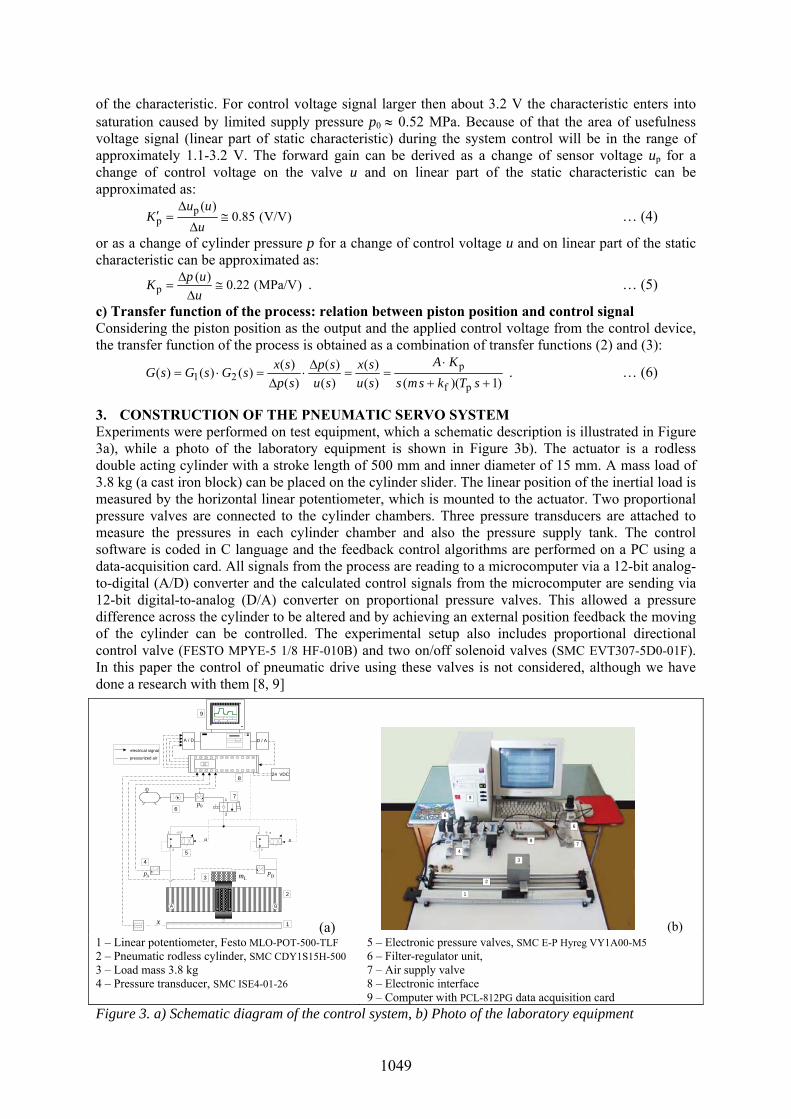
3. CONSTRUCTION OF THE PNEUMATIC SERVO SYSTEM Experiments were performed on test equipment, which a schematic description is illustrated in Figure 3a), while a photo of the laboratory equipment is shown in Figure 3b). The actuator is a rodless double acting cylinder with a stroke length of 500 mm and inner diameter of 15 mm. A mass load of 3.8 kg (a cast iron block) can be placed on the cylinder slider. The linear position of the inertial load is measured by the horizontal linear potentiometer, which is mounted to the actuator. Two proportional pressure valves are connected to the cylinder chambers. Three pressure transducers are attached to measure the pressures in each cylinder chamber and also the pressure supply tank. The control software is coded in C language and the feedback control algorithms are performed on a PC using a data-acquisition card. All signals from the process are reading to a microcomputer via a 12-bit analog-to-digital (A/D) converter and the calculated control signals from the microcomputer are sending via 12-bit digital-to-analog (D/A) converter on proportional pressure valves. This allowed a pressure difference across the cylinder to be altered and by achieving an external position feedback the moving of the cylinder can be controlled. The experimental setup also includes proportional directional control valve (FESTO MPYE-5 1/8 HF-010B) and two on/off solenoid valves (SMC EVT307-5D0-01F). In this paper the control of pneumatic drive using these valves is not considered, although we have done a research with them [8, 9]
x
A / D
24 VDC
6
2
BA
3Ap
5
REF01EZ
Bp
1
1
2
4
0p7
pressurized air
electrical signal
u31
2
u
ULN2803
31
2
Lm
8
9
D / A
(a)
1
2
3
7
5
4
6
8
9
(b) 1 – Linear potentiometer, Festo MLO-POT-500-TLF 2 – Pneumatic rodless cylinder, SMC CDY1S15H-500 3 – Load mass 3.8 kg 4 – Pressure transducer, SMC ISE4-01-26
5 – Electronic pressure valves, SMC E-P Hyreg VY1A00-M5 6 – Filter-regulator unit, 7 – Air supply valve 8 – Electronic interface 9 – Computer with PCL-812PG data acquisition card
Figure 3. a) Schematic diagram of the control system, b) Photo of the laboratory equipment
1049

4. EXPERIMENTAL RESULTS An example of pressure control in the cylinder chamber for varying reference signal is illustrated in Figure 5a). The pressure response is measured by pressure sensor and is presented as an output voltage uP, while the correspondingly pressure in the cylinder chamber p is shown on the right hand side of Figure 5a). Several experimental tests were also performed to evaluate the controller performance under conditions of unloaded and loaded drive. The experimental results for the response of pneumatic servo drive position control to a square-wave reference signal are shown in Figure 5b) and Figure 5c). The PD controller with parameters Kp=4.5, TD=0.12 (for unloaded drive) and Kp=5.5, TD=0.15 (for loaded drive) has been used in the control algorithm.
0 1 2 3 4 5 6 7 8 9 101
1.5
2
2.5
3
3.5
)(tuR
)(tu p
0
1
2
3
4
5
)(b
arp
)(V
up
0 1 2 3 4 5 6 7 8 9 100
50
100
150
200
250
300
350
400
450
500
)(m
mx
)(tx
)( tx R
)(st
0 1 2 3 4 5 6 7 8 9 100
50
100
150
200
250
300
350
400
450
500
)(m
mx
)( tx
)( tx R
)(st
0 1 2 3 4 5 6 7 8 9 10-2
-1
0
1
2
)(st
(a)
0 1 2 3 4 5 6 7 8 9 100
1
2
3
4
5
)(V
u
(b)
0 1 2 3 4 5 6 7 8 9 100
1
2
3
4
5
)(V
u
(c)
Figure 5. Experimental results for pneumatic servo drive control: a) pressure control, b) position control without load, c) position control with load mL=3.8 kg.
5. CONCLUSION In this paper the control of pneumatic servo drive using proportional pressure valves has been investigated. These valves are usually used for the pressure (and consequently the force) of pneumatic drives. In this paper beside the example of cylinder pressure control also the examples of position servo drive control are shown. The parameters of the process are obtained from experimentally measured data and controller parameters are tuned for an aperiodic response. On the basis of the experimental results it can be concluded that the proportional pressure valves have a potential for successfully implementation in hybrid force/position control tasks of the pneumatic servo drives.
6. REFERENCES [1] Liu, S., Bobrow, J. E., An Analysis of a Pneumatic Servo System and Its Application to a Computer Controlled Robot,
ASME J. of Dyn. Sys., Meas. and Ctrl., 110, pp. 228-235, 1988. [2] Mc Donell, B. W., Bobrow, J. E., 1993, Adaptive Tracking Control of an Air Powered Robot Actuator, ASME Journal
of Dynamic Systems Measurement and Control, 115, pp. 427-433. [3] Surgenor, B. W., Vaughan, N. D., 1997, Continuous Sliding Mode Control of a Pneumatic Actuator, ASME Journal of
Dynamic Systems, Measurement and Control, 119, pp. 578-581. [4] Varseveld, R. B., Bone, G. M. 1997, Accurate Position Control of a Pneumatic Actuator Using On/Off Solenoid Valves,
IEEE/ASME Transactions on Mechatronics, 2, pp. 195-204. [5] Lai, J. Y., Menq, C. H., Singh, R., 1990, Accurate Position Control of a Pneumatic Actuator, ASME Journal of
Dynamic Systems Measurement and Control, 112, pp. 734-739. [6] Tanaka, K., Yamada, Y., Sakamoto, M., Uchikado, S., 1998, Model Reference Adaptive Control with Neural Network
for Electro-Pneumatic Servo System, Proc. of the 1998 IEEE, Int. Conf. on Control Application, Trieste, Italy. [7] Sorli, M., Figliolini, G., Pastrorelli, S., Dynamic Model and Experimental Investigation of a Pneumatic Proportional
Pressure Valve, IEEE/ASME Trans. on Mechatronics, 9, pp. 78-86, 2004. [8] Šitum, Ž., Pavković, D., Novaković, B., Servo Pneumatic Position Control Using Fuzzy PID Gain Scheduling, ASME
J. of Dyn. Sys. Meas. and Ctrl., Vol. 126, No.2, pp. 376-387, June 2004.
1050

[9] Šitum, Ž., Essert, M., Modeling, Simulation and Control of a Pneumatic Servo System with On/off Solenoid Valves, 5th EUROSIM Congr. on Modeling and Simulation, ESIEE Paris, Marne la Vallée, September, 06-10, 2004.
1051