Embed Size (px)
Citation preview

1
Pressure Regulator133 / 233
Benefits■ Accurate regulation■ Exchangeable component
technique■ Easy maintenance■ Suitable for HTB
requirements■ DVGW-approval (DIN 3380/81,
VP 200).
DescriptionThe 133/233 regulator is adirect-acting, spring loadedregulator with an integratedsafety shut-off device.
The lever system ensures exactoutlet pressure, and fastresponse when the flow ratevaries.
ApplicationsThey are designed forresidential and industrial use,such as industries, and heatingplants, as well as for allinstallations where accuratepressure control, easyadjustment and fast responsetimes are required, such as forburners, industrial ovens,boilers, etc.
Pressure Regulator 133 / 233
Technical features■ Inlet pressure range Pi: 0.05 – 8.0 bar■ Outlet pressure range Po: 10 mbar – 0,7 bar■ Accuracy class AC5/10, SG10/20, AG10/5■ Operating temperature -20°C to +60°C ■ Ambient Temperature -30°C to +60°C ■ Acceptable gases Natural gas, propane, butane, air,
nitrogen and all non-corrosive gases.■ Safety devices Optional built-in safety shut-off valve:
OPSO: Over-pressure shut-off (SSV-I, 033) UPSO: Under-pressure shut-off (SSV-II)
■ Options Safety diaphragmSafety Relief valve
Connections■ Sizes DN 25, DN 40 and DN 50 ■ Dimensions see table page 6■ Flanges PN16 DIN, ANSI 150■ Thread G 3/4, G 1, G1 1/2
Body GGG 40, DIN 1693Actuator GD-Al Si 12, DIN 1725Body SSV BrassInternal parts Brass/Steel, zinc protected Seals NBR rubber/Viton Diaphragm NBR rubber/NBR rubber, reinforced fabric
Construction
2
Pressure Regulator133 / 233
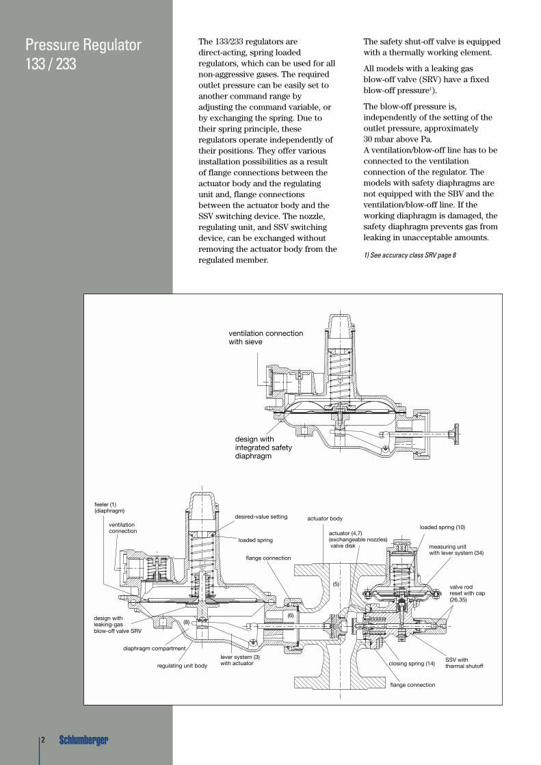
The 133/233 regulators aredirect-acting, spring loadedregulators, which can be used for allnon-aggressive gases. The requiredoutlet pressure can be easily set toanother command range byadjusting the command variable, orby exchanging the spring. Due totheir spring principle, theseregulators operate independently oftheir positions. They offer variousinstallation possibilities as a resultof flange connections between theactuator body and the regulatingunit and, flange connectionsbetween the actuator body and theSSV switching device. The nozzle,regulating unit, and SSV switchingdevice, can be exchanged withoutremoving the actuator body from theregulated member.
The safety shut-off valve is equippedwith a thermally working element.
All models with a leaking gasblow-off valve (SRV) have a fixedblow-off pressure1).
The blow-off pressure is,independently of the setting of theoutlet pressure, approximately30 mbar above Pa.A ventilation/blow-off line has to beconnected to the ventilationconnection of the regulator. Themodels with safety diaphragms arenot equipped with the SBV and theventilation/blow-off line. If theworking diaphragm is damaged, thesafety diaphragm prevents gas fromleaking in unacceptable amounts.
1) See accuracy class SRV page 8
diaphragm compartment
feeler (1)(diaphragm)
ventilationconnection
desired-value setting
loaded spring
loaded spring (10)
flange connection
flange connection
actuator body
actuator (4,7)(exchangeable nozzles)valve disk measuring unit
with lever system (34)
valve rodreset with cap(26,35)
SSV withthermal shutoffclosing spring (14)
lever system (3)with actuatorregulating unit body
design withleaking-gas blow-off valve SRV
(8)(6)
(5)
ventilation connectionwith sieve
design withintegrated safetydiaphragm

3
Pressure Regulator133 / 233
Technical Data and Type Designation
Type 133, Pi 0.05 - 4.0 bar■ Pressure rate Inlet pressure■ PN 1 0.05 - 1.0 bar■ PN 4 0.35 - 4.0 bar■ Outlet pressure 8 - 420 mbar■ Flow rate, up to 65 m3/h Natural gas■ Working temperature -20° bis +60°C■ Connection / Size see page 5
Type 233, Pi 0.05 - 4.0 bar■ Pressure rate Inlet pressure■ PN 1 0.05 - 1.0 bar■ PN 4 0.37 - 4.0 bar■ Outlet pressure 8 - 700 mbar■ Flow rate, up to 400 m3/h Natural gas ■ Working temperature -20° bis +60°C■ Connection / Size see page 5
Type 133, Pi > 4.0 - 6.0 bar ■ Pressure rate Inlet pressure ■ PN 6 0.35 - 6.0 bar■ Max. orifice-Ø 3/16” (4.7mm)■ Outlet pressure 20 - 420 mbar■ Flow rate, up to 65 m3/h Natural gas ■ Working temperature -20° bis +60°C ■ External impulse■ Connection / Size see page 5
Designation of regulator 133 and 2331
for Pe 0.1 - 4.02 barapproved according VP 200,DIN 3380 / 81 with DVGW-Reg. No.,with “t” (HTB):- 31 without safety devices - 32 with SRV- 61 SSV Pso ≥ 400 mbar- 62 SSV Pso ≥ 400 mbar and SRV- 64 SSV Pso and Psu- 66 SSV Pso and Psu and SRV- 71 SSV Pso ≤ 450 mbar- 72 SSV Pso ≤ 450 mbar and SRV- 77 SSV Pso ≤ 450 mbar, SRV and
gas loss protection, PN 1 (only 133) - 630 SSV Pso ≥ 400 mbar and safety
diaphragm, PN 1(133 and 233-8”/-12”)
- 650 SSV Pso and Psu, as well assafety diaphragm, PN 1(133 and 233-8”/-12”)
- 730 SSV Pso ≤ 450 mbar and safetydiaphragm, PN 1(133 and 233-8”/-12”)
- 770 SSV Pso ≤ 450 mbar, gas lossprotection and safety diaphragm,PN 1 (only regulator 133)
(1) select the diaphragm housing -8" or -12"(2) note the max. orifice-Ø

4
Pressure Regulator133 / 233
Type 233, Pi > 4.0 - 6.0 bar■ Pressure rate Inlet pressure ■ PN 6 0.35 - 6.0 bar■ Max. orifice-Ø 3/8” (10mm)■ Outlet pressure 20 - 700 mbar■ Flow rate, up to 400 m3/h Natural gas ■ Working temperature -20° bis +60°C ■ External impulse■ Connection / Size see page 5
Designation of regulator 133 and 2331
for Pe >4.0 - 6.02 barapproved according DIN 3380 / 81with DVGW-Reg. No., without “t”:- 32 with SRV- 66 SSV pso and psu, as well as SRV
(1) select the diaphragm housing -8" or -12"(2) note the max. orifice-Ø
Designation of regulator 133 and 2331
for Pi up to 8.02 bar without DVGW-Reg N°.- 31 without safety devices- 32 with SRV- 34 with gas loss protection- 36 with gas loss protection
and SRV- 61 SSV Pso- 62 SSV Pso and SRV- 64 SSV Pso and Psu- 66 SSV Pso and Psu and SRV
Type DesignationExample:Regulator type 233, pressure stagePN 4, 12” diaphragm housing, SSV
for upper shut off ≤ 450 mbar, withsafety relief valve (SRV):
(1) no digit for pressure rate PN 1(2) no diaphragm housing size
for type 133(3) Type 133 single pipe marked 133-E
Type 233 – 12 – 4 – 72
Type3
Diaphragm housing2
Pressure rate1
Safety shut-off valve (see table)
Body GGG 40, DIN 1693Diaphragm housing GD-Al Si 12 DIN 1725SSV-Body Brass, hot pressedOrifice BrassDiaphragm NBR/NBR reinforcedO-rings NBR/VitonValve disk regulator Aluminium/NBRValve disk SSV Brass/NBR
Construction

5
Pressure Regulator133 / 233 Regulator variants
InstallationPlease indicate desired installatingposition when you order. If nototherwise stated, the regulators areassembled and adjusted for normal
installation (position 2):Regulator 133-vent pointing outward,Regulator 233-vent pointing inward.
Type 133 DN 25, PN 16ANSI 150
Female thread
Male thread
DN 25, PN 16
G 3/4”, G1”3/4”-, 1”-NPT3/4”-, 1”-BSPT
G1 1/2”(140 mmlength)
G1 1/2”(160 mmlength)
DN 50, PN 16ANSI 150
DN 40, PN 16ANSI 150
Female threadG1 1/2”, 1 1/2” NPT1 1/2”-BSPT
SSV
DN 25, 133-E
SSV
Type 233-12
Type 233-8
Pos. 1
Pos. 2 Pos. 4* Pos. 6
Pos. 7 Pos. 8 Pos. 9 Pos. 10
Pos. 3* Pos. 5Regulator 233-ventpointing outward
Regulator 233-ventpointing outward
*) Pos. 3 and 4: Not to use for 233-8 (-12) -71/ -72/ -730

6
Dimension, Type 133-ER L N
Rp 1 110 41Rp 1-1/2” 140 50
Pressure Regulator133 / 233
Dimensions
Model Thread Flange A B C’ C D E F G H J K Weight in kgType Size Ventilation (approx.)
(1) (2) Connection (1) (2)133- 3/4“/1” DN 25 190 155 100 160 170 100 100 75 120 Rp 3/4 74 4 6233-12 1 1/2“ DN 40 350 250 150 200 265 155 115 75 120 Rp 1 110 11 15233-12 - DN 50 350 250 - 200 265 155 115 75 120 Rp 1 110 - 16233-8 1 1/2“ DN 40 260 250 150 200 220 125 115 75 120 Rp 1 105 9 13233-8 - DN 50 260 250 - 200 220 125 115 75 120 Rp 1 105 - 14
J
J

7
Pressure Regulator133 / 233
Command and adjustable range
Command ranges for Pressure SpringsRegulator Type Command range Part No. Colour marking
9 – 15 mbar 955-200-08 red133 14 – 20 mbar 955-200-09 blue
with gas loss 18 – 26 mbar 955-201-06 silverprotection 24 – 40 mbar 955-202-98 yellow
38 – 53 mbar 955-200-11 orange8 – 16 mbar 955-200-08 red12 – 20 mbar 955-200-09 blue15 – 35 mbar 955-200-10 green
13330 – 70 mbar 955-200-11 orange50 – 140 mbar 955-200-12 black-white100 – 210 mbar 955-200-83 silver
133 HP 140 – 420 mbar 955-200-84 black8 – 16 mbar 955-200-13 red12 – 20 mbar 955-200-14 blue15 – 35 mbar 955-200-15 green
233-1230 – 70 mbar 955-200-16 orange70 – 140 mbar 955-200-17 black100 – 210 mbar 955-200-18 metal blank30 – 70 mbar 955-200-15 green70 – 140 mbar 955-200-16 orange
233-8140 – 300 mbar 955-200-17 black210 – 450 mbar 955-200-18 metal blank420 – 700 mbar 955-200-69 silver
233-8 HP955-200-18 metal blank
Adjustable ranges for SSV, Type 033 for upper shut-offShut-off Adjustable range Part No. Colour markingUpper 40 – 70 mbar 955-200-22 red
(overpressure) 50 – 150 mbar 955-200-23 bluePso 140 – 450 mbar 955-200-24 green
Adjustable ranges SSV -I,-II for upper and lower shut-offShut-off Adjustable range Part No. Colour markingUpper 20 – 60 mbar 955-200-22 red
(overpressure) 50 – 120 mbar 955-200-23 blue100 – 400 mbar 955-200-24 green
Pso 300 – 600 mbar 955-200-52 brown400 – 1000 mbar 955-202-42 silver
Lower 8 – 50 mbar 955-200-32 red(underpressure) Psu

8
Pressure Regulator133 / 233
Accuracy class and closing groupregulator (AC, SG):Outlet pressure po:8 mbar - 20 mbar:AC 20 / SG 30>20 mbar - 50 mbar:AC 10 / SG 20> 50 mbar - 420 mbar:AC 5 / SG 10
Response closing group SSV:Upper response pressure Pso,40 –1000 mbar:AG 10Lower response pressure Psu,8 – 20 mbar:AG 30>20 – 50 mbar:AG 10
Accuracy class SRV:(Po + approx. 30 mbar) ± 10%
Pressure difference minimal,between outlet pressure Po and SSV shut-off:SSV 033: 20 mbar between Po and PsoSSV II, lower: 14 mbar between Po and PsuSSV II, upper: 20 mbar between Po and Pso
Ventilation:Gas pressure regulators without asafety diaphragm, and gas pressureregulators with an integrated safetyreliev valve (SRV), requireventilation and blow-off linesrespectively.The minimum diameters stipulatedby the DIN 3380 standards are DN 15.In order to ensure disturbance-freeregulation and a sufficiently quickresponse for load changes, thefollowing nominal widths andinstallation lengths have to beobserved:up to 3 m ventilation line: DN 20up to 5 m ventilation line: DN 25For longer lengths, at least DN 40 isrecommended.
Adjustable Data InletOutlet Pressure Pressure Orifice Inserts
Po (mbar) Pi (bar)Spring range / 12.5 mm 10 mm 8 mm 6.3 mm 4.7 mm 3 mm
No. / colour (1/2”) (3/8”) (5/16”) (1/4”) (3/16”) (1/8”)Po = 20 mbar 0.1 16 15 12 11 7 3
Command Range 0.3 27 26 18 14 12 615 – 35 mbar 0.5 32 28 19 17 15 8
955-200-10 green 1.0 38 37 20 20 19 11Po = 50 mbar 0.1 - - - - - -
Command Range 0.3 20 16 12 10 7 530 – 70 mbar 0.5 24 20 14 12 10 6
955-200-11 orange 1.0 29 26 17 16 14 10Po = 100 mbar 0.1 - - - - - -
Command Range 0.3 21 18 12 10 9 435 – 140 mbar 0.5 28 23 16 12 10 6
955-200-12 blk-white 1.0 40 38 23 19 16 10
Regulator Type 133-E, Body DN 25,Pe max 1.0 bar
Flow rate in m3/h natural gas instandard state (ρn = 0.78 kg/m3)

9
Adjustable Data InletOutlet Pressure Pressure1 Orifice Inserts
Po (mbar) Pi (bar)Spring range / 12.5 mm 10 mm 8 mm 6.3 mm 4.7 mm 3 mm
No. / colour (1/2”) (3/8”) (5/16”) (1/4”) (3/16”) (1/8”)0.1 24 17 16 9 - -0.3 40 36 29 22 13 6
Po = 20 mbar 0.5 48 46 40 30 17 8Command Range 1.0 61 56 53 41 25 12
15 – 35 mbar 1.5 - 63 61 56 33 14Pressure Spring 2.0 - 64 63 57 38 18
955-200-10 3.0 - - - 59 51 24green 4.0 - - - 64 52 31
5.0 - - - - 53 356.0 - - - - 54 408.0 - - - - 60 500.1 14 13 11 - - -0.3 31 29 22 16 12 4
Po = 50 mbar 0.5 44 42 37 24 15 8Command Range 1.0 58 52 46 40 24 11
30 – 70 mbar 1.5 - 59 57 54 30 14Pressure Spring 2.0 - 61 60 56 35 16
955-200-11 3.0 - - - 60 48 22orange 4.0 - - - 65 53 27
5.0 - - - - 54 306.0 - - - - 56 368.0 - - - - 66 500.2 22 18 14 12 8 30.3 33 28 18 16 11 4
Po = 100 mbar 0.5 50 35 28 24 12 8Command Range 1.0 60 52 48 39 23 12
50 – 140 mbar 1.5 - 58 56 52 29 13Pressure Spring 2.0 - 60 59 55 34 16
955-200-12 3.0 - - - 60 48 21black-white 4.0 - - - 63 52 25
5.0 - - - - 60 316.0 - - - - 65 358.0 - - - - 70 50
(1) With Pi > 4.0 bar, external impulse is required.(2) The volumes below the lines are not regulated with the accuracy indicated.
Pressure Regulator133 / 233
Adjustable DataOutlet Pressure Inlet
Po (mbar) PressureOrifice
Spring range / Pi (bar)∅ 12.5 mm
No. / colourPo = 20 mbar 0.1 13
Command Range 0.3 2018 – 26 mbar 0.5 25955-2001-06 1.0 32
Po = 50 mbar 0.15 14Command Range 0.3 22
38 – 53 mbar 0.5 27955-200-11 1.0 34
Regulator Type 133-77 and -770(with gas loss protection),Body DN 25, Pe max 1.0 barFlow rate in m3/h natural gas instandard state (ρn = 0.78 kg/m3)
Regulator Type 133,Actuator Body DN 25
Flow rate in m3/h natural gas instandard state (ρn = 0.78 kg/m3)(see footnotes 1. and 2.)

10
Pressure Regulator133 / 233
Adjustable Data InletOutlet Pressure Pressure1 Orifice Inserts
Po (mbar) Pi (bar)Spring range / 12.5 mm 10 mm 8 mm 6.3 mm 4.7 mm 3 mm
No. / colour (1/2”) (3/8”) (5/16”) (1/4”) (3/16”) (1/8”)0.1 - - - - - -0.3 18 15 12 10 7 3
Po = 140 mbar 0.5 25 21 17 14 10 6Command Range 1.0 44 36 29 22 17 10100 – 210 mbar 1.5 - 46 38 28 24 13
Pressure Spring 2.0 - 53 43 35 29 16955-200-83 3.0 - - 56 47 39 22
silver 4.0 - - - 59 49 265.0 - - - - 55 316.0 - - - - 65 358.0 - - - - 79 460.5 18 15 11 8 6 -1.0 35 29 23 16 13 9
Po = 300 mbar 1.5 - 38 33 25 18 12Command Range 2.0 - 46 40 33 25 15140 – 420 mbar 3.0 - - 53 43 38 21
Pressure Spring 4.0 - - 66 51 46 26955-200-84 5.0 - - - - 55 31
black 6.0 - - - - 65 358.0 - - - - 79 420.7 26 22 17 12 10 61.0 33 28 21 17 12 8
Po = 400 mbar 1.5 - 37 31 26 16 10Command Range 2.0 - 44 38 31 23 12140 – 420 mbar 3.0 - - 50 41 36 18
Pressure Spring 4.0 - - 64 49 44 24955-200-84 5.0 - - - - 53 29
black 6.0 - - - - 63 338.0 - - - - 77 40
(1) With Pi > 4.0 bar, external impulse is required.(2) The volumes below the lines are not regulated with the accuracy indicated.
Regulator Type 133,Actuator Body DN 25
Flow rate in m3/h natural gas instandard state (ρn = 0.78 kg/m3)(see footnotes 1. and 2.)

11
Pressure Regulator133 / 233
Adjustable Data InletOutlet Pressure Pressure1 Orifice Inserts / Valve Disk Angle
Po (mbar) Pi (bar)Spring range / 25 mm (1”) 20 mm (3/4”) 12.5 mm (1/2”) 10 mm (3/8”) 6.3 mm (1/4”)
No. / colour 30° 10° 10° 10° 10°0.1 75 58 40 24 120.3 142 114 82 48 230.5 188 149 110 64 32
Po = 20 mbar 1.0 250 208 158 98 47Command Range 1.5 280 241 195 125 57
15 – 35 mbar 2.0 - 260 215 147 68Pressure Spring 3.0 - 300 266 190 92
955-200-15 4.0 - 310 300 210 113green 5.0 - - 300 230 120
6.0 - - 300 250 1308.0 - - - 250 1600.1 51 43 26 20 -0.3 125 95 62 43 210.5 169 130 88 58 29
Po = 50 mbar 1.0 250 190 140 95 46Command Range 1.5 286 228 180 120 57
30 – 70 mbar 2.0 - 254 210 140 68Pressure Spring 3.0 - 295 250 190 90
955-200-16 4.0 - 315 280 220 110orange 5.0 - - 300 230 122
6.0 - - 300 250 1308.0 - - - 250 1600.2 73 52 38 25 150.3 110 81 54 36 200.5 160 119 79 53 30
Po = 100 mbar 1.0 237 183 136 90 44Command Range 1.5 266 221 168 119 57
70– 140 mbar 2.0 - 258 204 142 65Pressure Spring 3.0 - 290 248 191 87
955-200-17 4.0 - 319 277 230 109black 5.0 - - 300 240 124
6.0 - - 300 250 1308.0 - - - 250 1600.4 140 107 70 45 220.5 175 134 90 56 27
Po = 200 mbar 1.0 304 224 156 98 43Command Range 1.5 355 272 207 127 57
100– 210 mbar 2.0 - 291 230 142 64Pressure Spring 3.0 - 350 287 190 86
955-200-18 4.0 - 376 310 230 110silver 5.0 - - 320 250 125
6.0 - - 330 260 1308.0 - - - 260 160
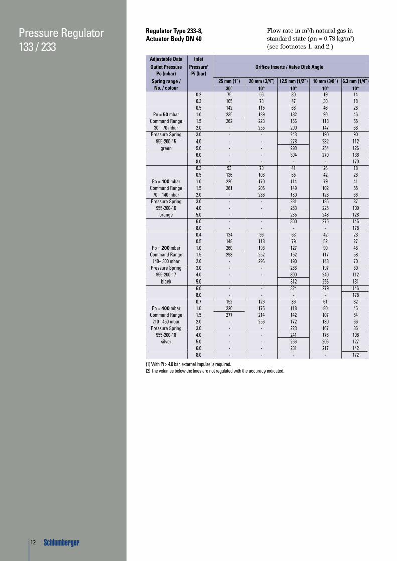
(1) With Pi > 4.0 bar, external impulse is required.(2) The volumes below the lines are not regulated with the accuracy indicated.
Regulator Type 233-12,Actuator Body DN 40
Flow rate in m3/h natural gas instandard state (ρn = 0.78 kg/m3
(see footnotes 1. and 2.)
12
Pressure Regulator133 / 233
Adjustable Data InletOutlet Pressure Pressure1 Orifice Inserts / Valve Disk Angle
Po (mbar) Pi (bar)Spring range / 25 mm (1”) 20 mm (3/4”) 12.5 mm (1/2”) 10 mm (3/8”) 6.3 mm (1/4”)
No. / colour 30° 10° 10° 10° 10°0.2 75 56 30 19 140.3 105 78 47 30 180.5 142 115 68 46 26
Po = 50 mbar 1.0 235 189 132 90 46Command Range 1.5 262 223 166 118 55
30 – 70 mbar 2.0 - 255 200 147 68Pressure Spring 3.0 - - 243 190 90
955-200-15 4.0 - - 278 232 112green 5.0 - - 293 254 126
6.0 - - 304 270 1388.0 - - - - 1700.3 93 73 41 26 180.5 136 106 65 42 26
Po = 100 mbar 1.0 220 170 114 79 41Command Range 1.5 261 205 149 102 55
70 – 140 mbar 2.0 - 236 180 126 66Pressure Spring 3.0 - - 231 186 87
955-200-16 4.0 - - 263 225 109orange 5.0 - - 285 248 128
6.0 - - 300 275 1468.0 - - - - 1780.4 124 96 63 42 230.5 148 118 79 52 27
Po = 200 mbar 1.0 260 198 127 90 46Command Range 1.5 298 252 152 117 58
140– 300 mbar 2.0 - 296 190 143 70Pressure Spring 3.0 - - 266 197 89
955-200-17 4.0 - - 300 240 112black 5.0 - - 312 256 131
6.0 - - 324 279 1468.0 - - - - 1780.7 152 126 86 61 32
Po = 400 mbar 1.0 220 175 118 80 46Command Range 1.5 277 214 142 107 54
210– 450 mbar 2.0 - 256 172 130 66Pressure Spring 3.0 - - 223 167 86
955-200-18 4.0 - - 241 176 108silver 5.0 - - 266 206 127
6.0 - - 281 217 1428.0 - - - - 172
(1) With Pi > 4.0 bar, external impulse is required.(2) The volumes below the lines are not regulated with the accuracy indicated.
Regulator Type 233-8,Actuator Body DN 40
Flow rate in m3/h natural gas instandard state (ρn = 0.78 kg/m3)(see footnotes 1. and 2.)
13
Pressure Regulator133 / 233
Adjustable Data InletOutlet Pressure Pressure1 Orifice Inserts / Valve Disk Angle
Po (mbar) Pi (bar)Spring range / 25 mm (1”) 20 mm (3/4”) 20 mm (3/4”) 12.5 mm (1/2”) 10 mm (3/8”) 6.3 mm (1/4”)
No. / colour 30° 30° 10° 10° 10° 10°0.1 97 74 66 41 25 120.3 214 180 142 79 50 230.5 288 250 187 119 69 30
Po = 20 mbar 1.0 385 360 267 182 106 46Command Range 1.5 425 400 292 230 128 57
15 – 35 mbar 2.0 - 410 317 255 153 68Pressure Spring 3.0 - - 362 324 205 86
955-200-15 4.0 - - 394 340 240 105green 5.0 - - - 350 264 118
6.0 - - - 362 288 1308.0 - - - - 305 1500.1 66 52 45 31 20 -0.3 165 130 110 65 43 220.5 245 200 157 97 60 29
Po = 50 mbar 1.0 387 320 240 163 98 45Command Range 1.5 421 390 287 219 127 55
30 – 70 mbar 2.0 - 410 317 255 152 66Pressure Spring 3.0 - - 365 312 205 89
955-200-16 4.0 - - 394 340 240 110orange 5.0 - - - 350 264 123
6.0 - - - 362 288 1408.0 - - - - 305 1600.2 95 65 60 40 30 140.3 160 117 105 65 44 210.5 241 178 155 97 62 29
Po = 100 mbar 1.0 380 307 260 162 98 45Command Range 1.5 446 379 326 216 126 57
70– 140 mbar 2.0 - 410 376 255 153 69Pressure Spring 3.0 - - 420 320 205 91
955-200-17 4.0 - - 430 375 240 110black 5.0 - - - 390 270 125
6.0 - - - 405 300 1408.0 - - - - 310 1600.4 165 125 110 70 45 250.5 204 150 133 83 55 30
Po = 200 mbar 1.0 320 248 221 149 97 45Command Range 1.5 371 310 267 198 126 57
100– 210 mbar 2.0 - 360 305 230 152 71Pressure Spring 3.0 - - 360 300 205 91
955-200-18 4.0 - - 400 320 240 110silver 5.0 - - - 330 265 125
6.0 - - - 350 300 1408.0 - - - - 310 160
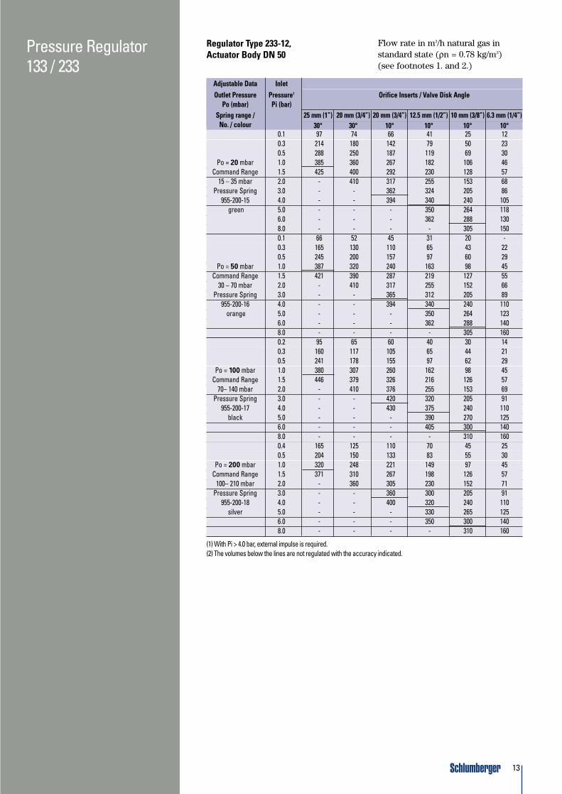
(1) With Pi > 4.0 bar, external impulse is required.(2) The volumes below the lines are not regulated with the accuracy indicated.
Regulator Type 233-12,Actuator Body DN 50
Flow rate in m3/h natural gas instandard state (ρn = 0.78 kg/m3)(see footnotes 1. and 2.)

14
Pressure Regulator133 / 233
Adjustable Data InletOutlet Pressure Pressure1 Orifice Inserts / Valve Disk Angle
Po (mbar) Pi (bar)Spring range / 25 mm (1”) 20 mm (3/4”) 20 mm (3/4”) 12.5 mm (1/2”) 10 mm (3/8”) 6.3 mm (1/4”)
No. / colour 30° 30° 10° 10° 10° 10°0.2 75 60 48 34 22 140.3 122 83 71 52 33 200.5 187 148 117 74 49 28
Po = 50 mbar 1.0 321 266 208 151 104 45Command Range 1.5 352 320 240 190 129 55
30 – 70 mbar 2.0 - 370 270 231 155 66Pressure Spring 3.0 - - - 300 208 94
955-200-15 4.0 - - - 340 236 117green 5.0 - - - 349 259 130
6.0 - - - 358 281 1418.0 - - - - - 1680.3 94 78 75 45 28 200.5 137 116 108 70 42 28
Po = 100 mbar 1.0 293 241 189 122 83 46Command Range 1.5 342 332 232 164 107 55
70 – 140 mbar 2.0 - 401 270 208 134 66Pressure Spring 3.0 - - - 281 189 92
955-200-16 4.0 - - - 317 237 113orange 5.0 - - - 340 251 131
6.0 - - - 356 270 1468.0 - - - - - 1720.4 115 95 88 55 38 220.5 154 120 116 69 48 27
Po = 200 mbar 1.0 293 241 198 127 93 45Command Range 1.5 363 343 252 181 121 57
140– 300 mbar 2.0 - 414 296 228 147 69Pressure Spring 3.0 - - - 304 199 95
955-200-17 4.0 - - - 350 231 117black 5.0 - - - 378 262 139
6.0 - - - 392 284 1508.0 - - - - - 1810.7 160 123 110 81 62 29
Po = 400 mbar 1.0 221 165 153 113 82 40Command Range 1.5 294 216 191 142 110 54
210– 450 mbar 2.0 - 274 231 170 128 66Pressure Spring 3.0 - - - 226 167 91
955-200-18 4.0 - - - 252 200 112silver 5.0 - - - 278 232 133
6.0 - - - 295 255 1508.0 - - - - - 183
(1) With Pi > 4.0 bar, external impulse is required.(2) The volumes below the lines are not regulated with the accuracy indicated.
Regulator Type 233-8, Actuator Body DN 50
Flow rate in m3/h natural gas instandard state (ρn = 0.78 kg/m3
(see footnotes 1. and 2.)

15
Pressure Regulator133 / 233
feeler (1)(diaphragm)
ventilation connection
diaphragm compartment
design withleaking-gas SBV
desired-value setting
loaded spring (2)
lever system (3)with actuatorregulating unit body
flange connection
closing spring (14)
flange connection
actuator body
actuator (4,7)(exchangeable nozzles)valve disk
loaded spring (10)
valve rod resetwith cap (26,35)
measuring unit withlever system (34)
(8)(6)
(5)
Operating PrincipleThe function of a regulator is to keepthe outlet pressure constant,independently of the inlet pressureand the gas flow. At zero consumption(Q = 0), they close tightly. Thecomparator (1) is loaded with a spring(2) and transmits its movement to theactuator (4) by means of a leversystem (3). The desired values areachieved by the respective commandvariable (spring load). The venturieffect, which is achieved by thedesign of the body, outlet section (5)and connection channel (6) to thecomparator (1), overcomes the springcharacteristics and generates a slightincrease in the outlet pressure at anincreasing flow. Without gas flowing,the regulator is open, i.e., the setcommand value (spring force) pressesthe comparator (1) as well as thelever system (3) downwards; theactuator opens and gas flows throughthe orifice (7). As a result, an outletpressure can develop and generate aforce at the comparator (1), whichcounteracts the set command value.
If this force exceeds the commandvalue, the rods (3) are lifted by thecomparator (1), and the valve disk (4)starts to narrow the clearance area atthe orifice (7) thereby throttling thegas flow. If the outlet pressure fallsdue to the sinking gas volume behindthe orifice (7) and, hence, in thediaphragm compartment (8), theactuator (4) is opened by thedominating spring force. Thischanging process is repeated until abalance between the command valueand the outlet pressure on thecomparator (1) depending on the gasflow, is achieved. If the actuator (4.7)is damaged, or if the rods (3) areblocked, the pressure in theregulating unit, and behind theactuator (4.7) can only increase untilthe integrated SSV responds andinterrupts the gas flow.

Schl
umbe
rger
res
erve
s th
e ri
ght
to c
hang
e th
ese
spec
ific
atio
ns w
itho
ut p
rior
not
ice
— E
U -
GA
- 00
026.
0 - G
B -
12.0
0
For further information, please contact your local Schlumberger representative.
16
Pressure Regulator133 / 233
with upperswitching pointPso ≥ 400 mbar
6 5 13
9
10
12
33
32
with lowerand upperswitching points
9
28
30
10
14
34 36 11 26 35limit of lift forupper shutoff
743113614
12
34
Over-pressure functionWhen the outlet pressure of a gaspressure regulator reaches aninadmissible value, the increasedpressure is also transmitted throughthe pulse bore (13) to the comparator(9) of the SSV.When the force below the comparator(9) reaches the force of the loadspring (10) against over-pressure, thecomparator (9) with the lever system(11) (for SSV with upper switchingpoint) and with the guide bush (28)(for SSV with upper and lowerswitching points) is pushed upwards.The lever system (11) is released sothat the force of the closing spring(14) is set free, and the valve disk (12)is pushed against the orifice (7).
Under-pressure functionWhen the outlet pressure of theregulator falls to such a degree thatthe force below the comparator (9)becomes smaller than the force of thespring for under-pressure (30), theload spring (30) pushes thecomparator downwards.
(Against over-pressure (10), the loadspring is mounted with the guide bush(28) at the retention shoulder (32)).The lever system is released so thatthe force of the closing spring (14) isalso released and the valve disk (12)is pushed against the orifice.
CommissioningThe SSV is commissioned by pullingout the valve rod (26) and engagingthe lever system (11). However, theSSV with upper and lower shut-offrequire that the pressure below thecomparator (9) lies above the lowerswitching pressure against under-pressure, and below the switchingpressure against over-pressure, sothat the lever (11) touches the arm(33) of the rocking lever (34).
The cap (35) and the valve rod (26)are equipped with threads.Consequently, a slight resetting of thevalve rod is possible.