Embed Size (px)
Citation preview

8/8/2019 Pressure Introduction
http://slidepdf.com/reader/full/pressure-introduction 1/15
1
ME-EM 3220 ENERGY LABORATORY
Pressure
Background:
Pressure
The normal stress on any plane through a fluid element at rest is equal to a unique value called the
fluid pressure, P, taken positive for compression by common convention.
The dimension of pressure is derived from the fundamental dimensions of mass, length and time
[1]
In the English Engineering Units system, pressure is commonly expressed in units of pounds per
square inch . For instance, automobile manuals state that “tires must be inflated to26 psi front and 24 psi rear.” in the SI system, pressure is expressed in Pascals where
[2]
The problem with the Pascal is that it is a very small unit, so the pressure is more often expressed in
kPa or MPa. For instance, atmospheric pressure is about100,000 Pa (at sea level -standard- value is101,350 Pa); it is much better represented as 100 kPa.
. [3]
Hydrostatic Pressure in Liquids
Hydrostatic pressure in liquids is expressed in terms of the height of a liquid column or “head” (i.e., in
of Hg, m of H2O, etc.). Atmospheric (standard) pressure is 760 mmHg. If the variations in ρ and g arenegligible, the pressure difference between any two arbitrary points in the fluid
[4]
Figure 1 Hydrostatic Pressure
P ][F [ ]
L[ ]2
----------M [ ]
L[ ] T [ ]2
-------------------= =
lb f in2 ⁄ ) or psi( )
1PaN
m2
------=
1 psi 6.9684 kPa=
p2 p1– ρg z2 z1–( )–=
+z
g
1
2
z2
z1

8/8/2019 Pressure Introduction
http://slidepdf.com/reader/full/pressure-introduction 2/15
2
Gage Pressure and Vacuum Pressure
If pressure is measured relative to the surrounding atmospheric pressure, then the pressure is referredto as gauge pressure. Common notation is Pgauge (psig). If the pressure is measured relative to an
absolute vacuum, then the pressure is referred to as the absolute pressure. Common notation is Pa or(psia).
Figure 2 Absolute, atmospheric, gage, and vacuum pressures
pabsolute
patm(absolute)
Atmospheric pressure
pgage
pabsolute
pvacuum
Zero pressure (Absolute vacuum)
Absolute pressure thatis less thanthe localatmospheric pressure
Absolute pressurethat isgreater than thelocalatmospheric pressure

8/8/2019 Pressure Introduction
http://slidepdf.com/reader/full/pressure-introduction 3/15
3
Pressure Measurements
There are many devices designed to measure pressure.
Gravitational Devices
The basic relation for the measurement of pressure by the use of manometers and barometers isderived from the consideration of a fluid at rest having a density ρ acted upon by the earth’s gravitational
acceleration g.
U-Tube Manometer
The U-Tube Manometer is usually made of glass or other transparent material in the shape of “U”. Bothends of the tube are open for the connection to the equipment, and is usually filled half way withmanometer fluid.
Figure 3 U-Tube Manometer
For the U-tube manometer, the pressure difference between the tubes is easily obtained from the
fundamental relation derived earlier.
[5]
Incl ined Tube Manometer
The inclined tube manometer is similar to manometer except that the tube has been tipped to a knownangle for greater accuracy. This manometer is very convenient for measuring small pressure differences.From the fundamental relation, the pressure is
P2
P1
z1
z2
p2 p1– ρg z2 z1–( )–=
p2 p1– ρg s2 s1–( ) θsin– ρg s2 s1–( )corrected
–= =

8/8/2019 Pressure Introduction
http://slidepdf.com/reader/full/pressure-introduction 4/15
4
Figure 4 Inclined Tube Manometer
Barometer
One of the devices which is used to determine the absolute atmospheric pressure is a mercury in
glass barometer. A sketch of such an instrument is shown below.
Figure 5 Mercury-in-Glass Barometer
If the value of the gravitational acceleration at the given location, and if the mercury density at thegiven temperature is also known, then
[6]
Po
Patm habs
ha
hHg
patm ρ Hgg h Hg ha–( ) po+=

8/8/2019 Pressure Introduction
http://slidepdf.com/reader/full/pressure-introduction 5/15
5
where is the vapor pressure of the mercury at the surrounding temperature.If the gravitational acceleration and/or mercury density is unknown, standard values for these may be
used as follows:
[7]
where is a correction to compensate for differences of gravitational acceleration. This correc-
tion is based on the latitude. at latitude.
Houghton is at latitude. The temperature correction corrects hobs to both the stan-
dard scale temperature of and the standard density of mercury at is
.
Elastic Transducers
The basic principle involved is, that a confined fluid at some pressure different from surroundings will
exert forces on the material confining the fluid. If the forces are sufficient to cause detectable stresses andresulting strain is in the elastic region of the material, such strains can be used to indicate the pressure
acting on the confined fluid.
Test Gauge Bourdon-Gauge s Tube
An example of this type of transducer is the Bourdon Tube Pressure Gauge, which is widely used to
measure pressure differences. The essential features of this gauge is shown on the sketch below.
Figure 6 Test Gauge-Bourdon Tube
po
patm ρ Hg 0
oC ≅
gstd hobs ∆hg ∆hT + +( )=
hg∆gstd 32.174 f t
2sec ⁄ or 9.80665 m
2sec ⁄ = 45.5°
47°7.5′ hT ∆62°F 16.7°C ( ) 32°F 0°C ( )
ρ Hg0°C 848.43 lb f t 3
13595.5 kg m3
⁄ ⁄ =
8/8/2019 Pressure Introduction
http://slidepdf.com/reader/full/pressure-introduction 6/15
6
The pressure sensing element is a tube of oval cross-section bent to a circular shape. One end of the
tube is fixed to the gauge case and is connected to the fluid whose pressure is to be measured. The otherend is closed and is free to move as it is connected via mechanical linkage and gear sector to a pointer. As
measured fluid pressure increases above that of surroundings, the tube cross-section tends to becomecircular and causes the tube to deflect at this second end. This motion is transmitted via linkage to the
pointer, which would directly indicate on the calibrated scale or dial the gauge pressure.
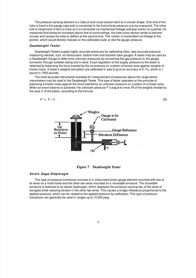
Deadweight Tester
Deadweight Testers supply highly accurate pressures for calibrating other, less accurate pressure
measuring devices, such as transducers, bottom-hole and bourdon-tube gauges. A tester may be used asa Deadweight Gauge to determine unknown pressures by connecting the gas pressure to the gauge
connector through suitable tubing and a valve. Exact regulation of the supply pressure to the tester isobtained by balancing the force exerted by the oil pressure on a piston of known area against weights of
known mass. A tester’s weights and piston are calibrated in sets to give an accuracy of 0.1%, which is 1pound in 1000 pounds.
The most accurate instruments available for measurement of pressures above the range where
manometers may be used is the Deadweight Tester. This type of tester operates on the principle ofbalancing a known mass against the force exerted by an unknown pressure on a piston of a known area.When an exact balance is achieved, the unknown pressure P is equal to mass M of the weights divided by
the area A of the piston, according to the formula
. [8]
Figure 7 Deadweight Tester
Strain Gage-Diaphragm
This type of pressure transducer consists of a unbounded strain gauge element mounted with two ofits wires on a fixed frame and the other two wires mounted on a moveable armature. The moveable
armature is fastened to an elastic diaphragm, which displaces the armature causing two of the wires toelongate while reducing tension in the other two wires. This causes a bridge imbalance proportional to the
applied pressure, which can be related to the applied pressure by calibration. This type of pressuretransducer can generally be used in ranges up to 10,000 psig.
P F A ⁄ =

8/8/2019 Pressure Introduction
http://slidepdf.com/reader/full/pressure-introduction 7/15
7
Figure 8 Strain Gage-Diaphragm
Semiconductor-on Bending Beam
This type of pressure transducer consists of four strain gauge elements bonded to a beam to measurethe bending strain. Two of the strain gauges are mounted on the bottom side of the beam to measure the
positive (tensile) strain, and the other two are mounted on the top side to measure the negative(compressive) strain. The diaphragm in this case supplies the force to the beam and isolates it from the
process. This type of pressure transducer can generally be used in ranges up to 30,000 psig.
Solid State-Piezo Resistive
Piezo Resistive pressure sensors operate based on the resistive dependence of sil icon under stress.Similar to a strain gauge, a piezoresistive sensor consists of a diaphragm onto which four pairs of silicon
resistors are bonded. Unlike the construction of a strain gauge sensor, here the diaphragm itself is made ofsilicon and the resistors are diffused into the silicon during the manufacturing process. Bonding thediaphgram to an unprocessed wafer of silicon completes the diaphragm. This type of pressure transducer
can generally be used in ranges up to 150 psig.
Figure 9 Solid State-Piezo Resistive

8/8/2019 Pressure Introduction
http://slidepdf.com/reader/full/pressure-introduction 8/15
8
Experiment 1
Inclined and U-Tube Manometers)
Figure 10 Schematic Diagram: U-Tube vs. Inclined Manometer
Apparatus
Incline manometer, U-Tube, Splitter
Procedure
1. Connect the two manometers to a common supply of pressure.2. Vary the pressure and obtain values for each reading.3. Set the scale to Zero readings.
4. Slowly apply small amount of pressure.
DO NOT GO ABOVE OR BELOW THE MANOMETER RANGE.5. Set the Incline manometer readings and get the U-Tube readings.
6. Plot vs. for both manometers on the same graph.7. Perform linear curve fit and calculate the slope.
INCLINEDMANOMETER U-TUBE
Pressure supply
0
Splitter
tube
tube
PatmP
atm
z∆
p∆ z∆

8/8/2019 Pressure Introduction
http://slidepdf.com/reader/full/pressure-introduction 9/15
9
Date : ___________ / _____ / 2002
Name :______________________
Section :______________________ Instructor’s initials : ___________
Experiment 1
Inclined and U-Tube Manometers
Table 1 [Inclined and U-Tube Manometer]
Inclined
Manometer
(in H2O)
Pressure
(Inclined)
(psi)
U-Tube
Manometer
(in Red oil)
U-Tube corrected
Manometer
(in H2O)
Pressure
(U-Tube)
(psi)
0.2
0.4
0.6
0.8
1.0
1.2
2.4
2.6
2.8
3.0
3.2
3.4
3.6
3.8
∆ p ρg∆ z= ∆ p ρg∆ z=

8/8/2019 Pressure Introduction
http://slidepdf.com/reader/full/pressure-introduction 10/15
10
Experiment 2
Barometric Pressure
Figure 11 Mercury Barameter
Apparatus
1. Laboratory mercury-in-glass barometer2. Airflow Developments LTD
Procedure
1. Zero the scale by using adjustable screw for compensating differential thermal expansion of tubeand scale. Make sure the end needle just touches the mercury.
2. Read the value of using Vernier scale.
3. Record the temperature using the thermometer attached to the barometer.4. Obtain the barometric pressure using the barometric corrections.
5. Latitude corrections,6. Temperature corrections, Calculate your atmospheric pressure using Equation [7]
7. Compare your results with the Air Flow Development LTD barometer readings.
Data:
hobserve
hg∆hT ∆

8/8/2019 Pressure Introduction
http://slidepdf.com/reader/full/pressure-introduction 11/15
11
Experiment 3
Calibration of a Pressure Gauge against Dead Weight Tester
Figure 12 Deadweight Tester
Apparatus
1. Dead weight tester.
2. Pressure gauge (for calibration)
Procedure
1. Turn the valve to the discharge position (fully counter clockwise or the valve is pointing awayfrom you)
2. Add 10 lbs weights on top of the piston ( Piston itself is 5 lbs).
3. Crank the Pressure (screw) adjuster clockwise until the weights float.4. Read the Pressure Gauge scale.
5. Repeat step 2 to 4 until the pressure reaches 100 psi. Each repetition shall be done with pres-sure increase of 10 lbs.
6. Plot a calibration curve. Measured Pressure (Pm) vs. Applied Pressure (Pa)
Pressure (screw) adjuster
Pressure Gauge
Piston
OilReservoir
Weights
Add WeightsHere
Valve

8/8/2019 Pressure Introduction
http://slidepdf.com/reader/full/pressure-introduction 12/15
12
Date : ___________ / _____ / 2002
Name :______________________
Section :______________________ Instructor’s initials : ___________
Experiment 3
Calibration of a Pressure Gauge against Dead Weight Tester
Table 2: [Dead Wight tester]
Trial # Papplied Pmeasured Trial # Papplied Pmeasured
1 10 6 60
2 20 7 70
3 30 8 80
4 40 9 90
5 50 10 100

8/8/2019 Pressure Introduction
http://slidepdf.com/reader/full/pressure-introduction 13/15
13
Experiment 4
Solid State Piezo Resistive, Semiconductor on Diaphragm
Figure 13 Semiconductor on Bending Beam, and Bourdon Tube Gauge against the Cali-brated Pressure Gauge
Apparatus
1. Strain-Gage Diaphragm2. Semiconductor-on Bending Beam3. Solid State-Piezo Resistive
4. Test Gauge-Bourdon Tube5. Calibrated Pressure Gauge
Main Valve Pressure (screw) adjuster
PressureGauge
1 2 3 4
red
hose
Pressure line
STRAIN GAGE-DIAPHRAGM
SEMICONDUCTOR-ON BENDING BEAM
SOLID STATE-PIEZO RESISTIVE
TEST GAUGE-BOURDON TUBE
Manifold
Calibrated Pressure Gauge
Quick
ConnectBlack Hose
Black Hose

8/8/2019 Pressure Introduction
http://slidepdf.com/reader/full/pressure-introduction 14/15
14
6. Manifold
Procedure
1. Insert the “Quick Connect” terminal from the manifold hose (red) to the in-line pressure source.2. Connect the other end of that manifold (adjacent to the mechanical scale) to a “tee” connector.
3. Feed one hose (black) to the Bourdon Tube Gauge and another hose (black) to the Strain GageDiaphragm.
4. Apply pressure from the in-line pressure source (10 psi) and record the readings you obtainedfrom both devices.
5. Disconnect the hose from Strain Gage Diaphragm and connect it to the Semiconductor-on
Bending Beam. Record the readings.6. Repeat step 5 for Solid State-Piezo Resistive.
7. Repeat the experiments at different pressure readings and fill in the table below.8. Calculate the error for all readings by taking the Calibrated Pressure Gauge readings as the true
readings.9. Plot all pressure readings against actual Pressure.

8/8/2019 Pressure Introduction
http://slidepdf.com/reader/full/pressure-introduction 15/15
15
Date : ___________ / _____ / 2002
Name :______________________
Section :______________________ Instructor’s initials : ___________
Experiment 4
Solid State Piezo Resistive, Semiconductor on Diaphragm
Questions :
• Are corrections for the barometer significant?• Does height from the earth’s surface effect the barometer reading?• Does the deadweight tester need to be corrected for gravity at this location?• Explain primary and secondary pressure measurements.
Table 3:
Calibrated
Pressure Gauge
(psi)
Test
Bourdon Tube
(psi)
Strain Gage Dia-
phragm
(psi)
Semiconductor on
Bending Beam
(psi)
Solid State-Piezo
Resistive
(psi)
10
15
20
25
30
35
40
45
50
55
60
65