Embed Size (px)
Citation preview
Aerospace Group Conveyance Systems Division Carter® Ground Fueling
SM64348 January 2011 Applicable additional manuals:
SM44315 Quick Disconnect Assy SM44646 Hose End Regulator SM47013 Hose End Regulator SM60129-1 Hose End Regulator SM428MISC Misc. Adapter Assemblies SM427MISC Misc. Adapter Assemblies SM44642 60427 Type Quick Disconnect Assy SM61154 Dry Break Disconnect Assy SM64001 Quick Disconnect Assy SM64015 Ball Valve
Maintenance Manual
Pressure Fueling Nozzle
Model 64348
SM64348 January 2011
2
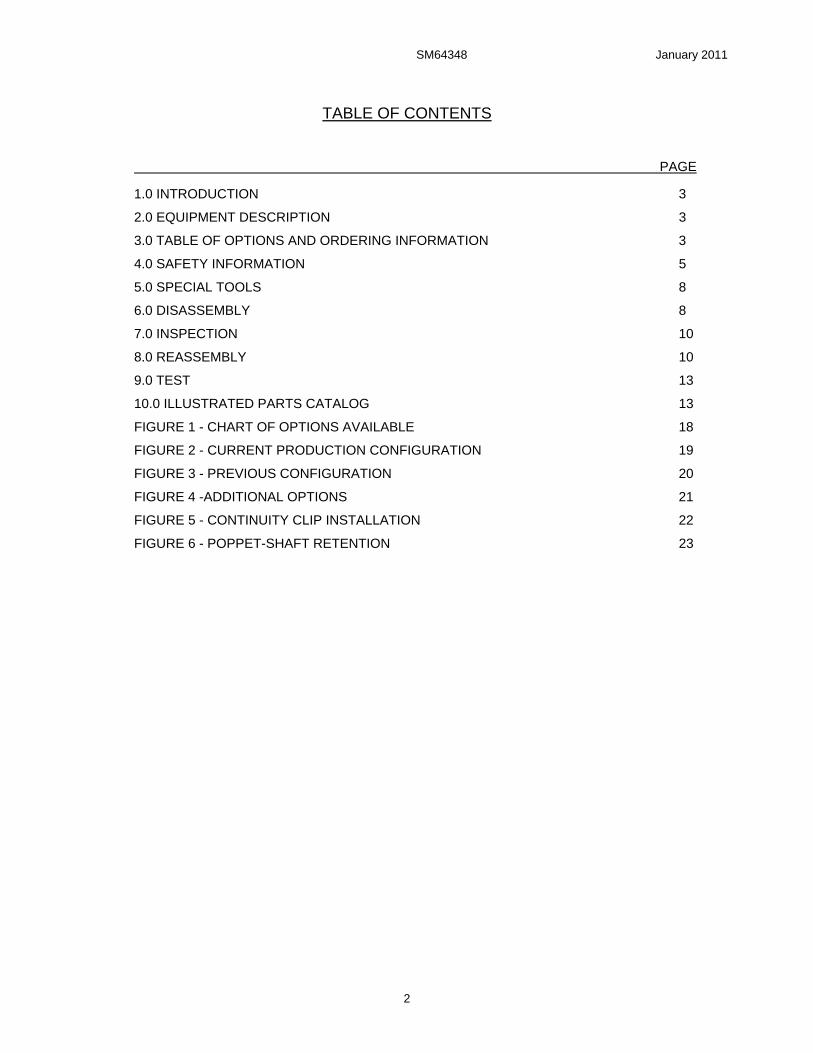
TABLE OF CONTENTS
PAGE
1.0 INTRODUCTION 3
2.0 EQUIPMENT DESCRIPTION 3
3.0 TABLE OF OPTIONS AND ORDERING INFORMATION 3
4.0 SAFETY INFORMATION 5
5.0 SPECIAL TOOLS 8
6.0 DISASSEMBLY 8
7.0 INSPECTION 10
8.0 REASSEMBLY 10
9.0 TEST 13
10.0 ILLUSTRATED PARTS CATALOG 13
FIGURE 1 - CHART OF OPTIONS AVAILABLE 18
FIGURE 2 - CURRENT PRODUCTION CONFIGURATION 19
FIGURE 3 - PREVIOUS CONFIGURATION 20
FIGURE 4 -ADDITIONAL OPTIONS 21
FIGURE 5 - CONTINUITY CLIP INSTALLATION 22
FIGURE 6 - POPPET-SHAFT RETENTION 23
SM64348 January 2011
3
Maintenance, Overhaul & Test Instructions Carter® Brand Model 64348 Pressure Fueling Nozzle
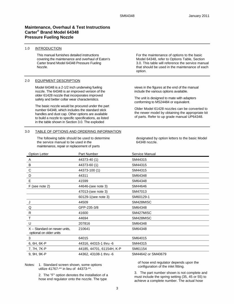
1.0 INTRODUCTION
This manual furnishes detailed instructions covering the maintenance and overhaul of Eaton’s Carter brand Model 64348 Pressure Fueling Nozzle.
For the maintenance of options to the basic Model 64348, refer to Options Table, Section 3.0. This table will reference the service manual that should be used in the maintenance of each option.
2.0 EQUIPMENT DESCRIPTION
Model 64348 is a 2-1/2 inch underwing fueling nozzle. The 64348 is an improved version of the older 61428 nozzle that incorporates improved safety and better collar wear characteristics.
The basic nozzle would be procured under the part number 64348, which includes the standard stick handles and dust cap. Other options are available to build a nozzle to specific specifications, as listed in the table shown in Section 3.0. The exploded
views in the figures at the end of the manual include the various options available.
The unit is designed to mate with adapters conforming to MS24484 or equivalent.
Older Model 61428 nozzles can be converted to the newer model by obtaining the appropriate kit of parts. Refer to up grade manual UP64348.
3.0 TABLE OF OPTIONS AND ORDERING INFORMATION
The following table should be used to determine the service manual to be used in the maintenance, repair or replacement of parts
designated by option letters to the basic Model 64348 nozzle.
Option Letter Part Number Service Manual
A 44373-40 (1) SM44315
B 44373-60 (1) SM44315
C 44373-100 (1) SM44315
D 44311 SM64348
E 41599 SM64348
F (see note 2) 44646-(see note 3) SM44646
47013-(see note 3) SM47013
60129-1(see note 3) SM60129-1
J 44509 SM428MISC
Q GFP-235-3/8 SM64348
R 41600 SM427MISC
T 44694 SM428MISC
U 207816 SM64348
X – Standard on newer units, optional on older units
210641 SM64348
3 64015 SM64015
6, 6H, 6K-P 44316, 44315-1 thru -6 SM44315
7, 7H, 7K-P 44185, 44701, 61154H, K-P SM61154
9, 9H, 9K-P 44362, 43108-1 thru -6 SM44642 or SM40679
Notes: 1. Standard screen shown, some options utilize 41767-** in lieu of 44373-**.
2. The "F" option denotes the installation of a hose end regulator onto the nozzle. The type
of hose end regulator depends upon the configuration of the inlet fitting.
3. The part number shown is not complete and must include the spring setting (35, 45 or 55) to achieve a complete number. The actual hose
SM64348 January 2011
4
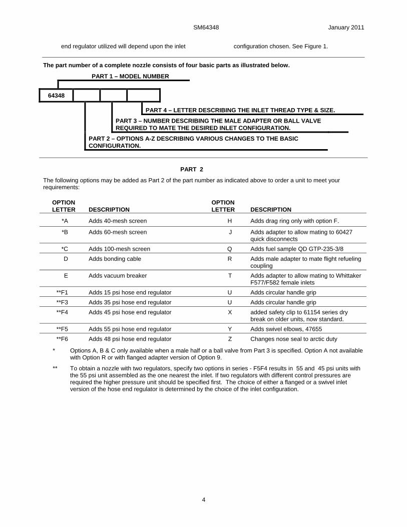
end regulator utilized will depend upon the inlet configuration chosen. See Figure 1.
The part number of a complete nozzle consists of four basic parts as illustrated below.
PART 1 – MODEL NUMBER
64348
PART 4 – LETTER DESCRIBING THE INLET THREAD TYPE & SIZE.
PART 3 – NUMBER DESCRIBING THE MALE ADAPTER OR BALL VALVE REQUIRED TO MATE THE DESIRED INLET CONFIGURATION.
PART 2 – OPTIONS A-Z DESCRIBING VARIOUS CHANGES TO THE BASIC CONFIGURATION.
PART 2
The following options may be added as Part 2 of the part number as indicated above to order a unit to meet your requirements:
OPTION LETTER DESCRIPTION
OPTION LETTER DESCRIPTION
*A Adds 40-mesh screen H Adds drag ring only with option F.
*B Adds 60-mesh screen J Adds adapter to allow mating to 60427 quick disconnects
*C Adds 100-mesh screen Q Adds fuel sample QD GTP-235-3/8
D Adds bonding cable R Adds male adapter to mate flight refueling coupling
E Adds vacuum breaker T Adds adapter to allow mating to Whittaker F577/F582 female inlets
**F1 Adds 15 psi hose end regulator U Adds circular handle grip
**F3 Adds 35 psi hose end regulator U Adds circular handle grip
**F4 Adds 45 psi hose end regulator X added safety clip to 61154 series dry break on older units, now standard.
**F5 Adds 55 psi hose end regulator Y Adds swivel elbows, 47655
**F6 Adds 48 psi hose end regulator Z Changes nose seal to arctic duty
* Options A, B & C only available when a male half or a ball valve from Part 3 is specified. Option A not available with Option R or with flanged adapter version of Option 9.
** To obtain a nozzle with two regulators, specify two options in series - F5F4 results in 55 and 45 psi units with the 55 psi unit assembled as the one nearest the inlet. If two regulators with different control pressures are required the higher pressure unit should be specified first. The choice of either a flanged or a swivel inlet version of the hose end regulator is determined by the choice of the inlet configuration.
SM64348 January 2011
5
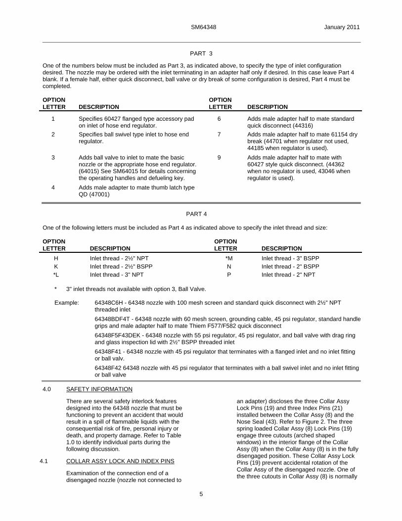
PART 3
One of the numbers below must be included as Part 3, as indicated above, to specify the type of inlet configuration desired. The nozzle may be ordered with the inlet terminating in an adapter half only if desired. In this case leave Part 4 blank. If a female half, either quick disconnect, ball valve or dry break of some configuration is desired, Part 4 must be completed. OPTION OPTION LETTER DESCRIPTION LETTER DESCRIPTION
1 Specifies 60427 flanged type accessory pad on inlet of hose end regulator.
6 Adds male adapter half to mate standard quick disconnect (44316)
2 Specifies ball swivel type inlet to hose end regulator.
7 Adds male adapter half to mate 61154 dry break (44701 when regulator not used, 44185 when regulator is used).
3 Adds ball valve to inlet to mate the basic nozzle or the appropriate hose end regulator. (64015) See SM64015 for details concerning the operating handles and defueling key.
4 Adds male adapter to mate thumb latch type QD (47001)
9 Adds male adapter half to mate with 60427 style quick disconnect. (44362 when no regulator is used, 43046 when regulator is used).
PART 4
One of the following letters must be included as Part 4 as indicated above to specify the inlet thread and size: OPTION OPTION LETTER DESCRIPTION LETTER DESCRIPTION
H Inlet thread - 2½" NPT *M Inlet thread - 3" BSPP K Inlet thread - 2½" BSPP N Inlet thread - 2" BSPP *L Inlet thread - 3" NPT P Inlet thread - 2" NPT
* 3" inlet threads not available with option 3, Ball Valve.
Example: 64348C6H - 64348 nozzle with 100 mesh screen and standard quick disconnect with 2½" NPT
threaded inlet
64348BDF4T - 64348 nozzle with 60 mesh screen, grounding cable, 45 psi regulator, standard handle grips and male adapter half to mate Thiem F577/F582 quick disconnect
64348F5F43DEK - 64348 nozzle with 55 psi regulator, 45 psi regulator, and ball valve with drag ring and glass inspection lid with 2½" BSPP threaded inlet
64348F41 - 64348 nozzle with 45 psi regulator that terminates with a flanged inlet and no inlet fitting or ball valv.
64348F42 64348 nozzle with 45 psi regulator that terminates with a ball swivel inlet and no inlet fitting or ball valve
4.0 SAFETY INFORMATION
There are several safety interlock features designed into the 64348 nozzle that must be functioning to prevent an accident that would result in a spill of flammable liquids with the consequential risk of fire, personal injury or death, and property damage. Refer to Table 1.0 to identify individual parts during the following discussion.
4.1 COLLAR ASSY LOCK AND INDEX PINS
Examination of the connection end of a disengaged nozzle (nozzle not connected to
an adapter) discloses the three Collar Assy Lock Pins (19) and three Index Pins (21) installed between the Collar Assy (8) and the Nose Seal (43). Refer to Figure 2. The three spring loaded Collar Assy (8) Lock Pins (19) engage three cutouts (arched shaped windows) in the interior flange of the Collar Assy (8) when the Collar Assy (8) is in the fully disengaged position. These Collar Assy Lock Pins (19) prevent accidental rotation of the Collar Assy of the disengaged nozzle. One of the three cutouts in Collar Assy (8) is normally
SM64348 January 2011
6
narrower than the other two. This assures that, even with badly worn adapters, a minimum of two Lock Pins (19) will be activated to prevent the nozzle from being opened when not connected to an adapter.
With the Collar Assy (8) locked in the disengaged position, the flat portion of a ramp integral to the Collar Assy (8) is positioned over a flat on the Lever (14) in a manner that prevents opening the Poppet (15).
When connecting to an aircraft, the Index Pins (21) mate with three slots in a serviceable MS24484 Adapter Flange to index the nozzle to the flange so the Collar Assy (8) mates with the flange lugs during engagement and prevents disengagement of the Collar Assy (8) from the flange without releasing the three spring loaded Collar Assy Lock Pins (19) to the Collar Assy (8) lock positions.
4.2 LEVER/COLLAR ASSY INTERLOCK AND OVER CENTER LINKAGE
Examination of the center portion of the Lever (14) on a disengaged nozzle discloses the fact that a flat edge of the Lever (14) is beneath the flat portion of a ramp that is integral to the Collar Assy (8). With the Collar Assy (8) locked by the Collar Assy Lock Pins (19), the Collar Assy (8) ramp prevents rotation of the Lever (14) to the poppet open position.
When the Collar Assy (8) is fully engaged to a serviceable MS24484 Adapter the Collar Assy ramp clears the Lever (14) and permits Lever (14) rotation to the open position.
With the Lever (14) fully open, the round portion of the Lever (14) prevents rotation of the Collar Assy (8) in the disengage direction until the Lever (14) has been fully closed.
These interlocks are designed to prevent accidental opening of the poppet of a disengaged nozzle or accidentally disengaging a nozzle with the poppet open.
The poppet operating internal linkage design is such that the linkage is "over center" at each extreme of travel (Lever (14) fully open against internal mechanical stop or fully closed against internal mechanical stop).
Thus, internal pressure against a closed poppet, when the linkage is against the closed mechanical stop, provides a force only in the closed direction.
In a similar manner, with the Lever (14) in the fully open/mechanical stop position, the 50 lb. force applied by the MS24484 Adapter Poppet Spring provides a force to maintain the open direction.
Refer to Service Bulletin SB3480801A for the latest information on the Lever (14) as it relates to safety. Contact Eaton or your Eaton Carter brand distributor for a copy if you do not have one.
4.3 SAFETY INSPECTIONS
Note: The frequencies recommended for the following inspections are our recommendations based on nozzles that have been in daily service for at least a year. The frequency that is required will depend upon the degree of maintenance extended to the equipment and to the age of the equipment. It is not possible for Eaton to recommend other than the safest possible frequencies.
4.3.1 NOZZLE INSPECTIONS - AT EACH REFUELING OPERATION
The following inspections of the Nozzle are recommended at each refueling operation:
A. Inspect the connection end and verify that the Index Pins (21) are intact, in place, and not excessively worn or damaged. Verify that all three Collar Lock Pins (19) are intact, undamaged and are extended and engage all three cutouts in the Collar Assy (8) and physically prevent Collar Assy (8) rotation.
This inspection can be accomplished without interruption of the normal operating procedure and without adding appreciably to the operation time by training the operator to automatically observe the connection end of the nozzle upon disconnection from the aircraft. If the Collar Lock Pins (19) do not spring into their correct position, it could mean that the aircraft adapter is defective and should be inspected (see paragraph 4.3.3) and reported as possibly being defective. If the Collar Lock Pins (19) are not extended and engaged in all three cutouts in the Collar Assy (8), the operator should squeeze the Lever (14) and Handle Grip (4) together while observing the connecting end of the nozzle. This should cause the Collar Lock Pins (19) to "spring" into the cutouts in the Collar Assy (8). If not, then the nozzle should be taken out of service.
B. On units with the thumb latch type disconnect (Options 4 or 7) check to be sure that Safety Clip (61) is present. Since it was an option on earlier units and now standard it may not be present. If Clip (61) is not present it is recommended that it be procured and installed as an additional safety device to prevent inadvertent disconnect of the unit.
C. Upon engagement to an aircraft and opening the nozzle but before operating the deadman control it is recommended that the operator attempt to remove the nozzle from the aircraft. This should not be possible. If it
SM64348 January 2011
7
can be removed, either the nozzle was never fully engaged onto the aircraft or needs repair, or the aircraft adapter, is in need of repair or replacement.
4.3.2 NOZZLES INSPECTIONS - MONTHLY BASIS
The following inspections of the Nozzle are recommended to be conducted on a monthly basis as a minimum:
A. Inspect the connection end and verify that the three Index Pins (21) are intact and in place. Verify that the three Collar Assy Lock Pins (19) are intact and in place and extended and engaging all three cutouts in the Collar Assy (8) and physically preventing Collar Assy (8) rotation. Check the Bearing Plate (42) containing the pins for possible cracks.
B. Prior to connecting the nozzle to the aircraft inspect the Lever (14) for cracks or looseness with the Screw (39) that attaches it to the nozzle. Do not use the nozzle if cracks or looseness is apparent.
C. Hold the nozzle with the outlet or connecting end facing such that it can be observed. Apply pressure on the Collar Assy (8) in the direction to connect the nozzle aircraft, counterclockwise, to take up the slack and inspect the relative location of the three Lock Pins (19) with respect to the cutouts in the Collar Assy (8). The two Lock Pins (19) that are engaged in the normally wider cutouts should not be resting against the edge of their respective cutouts. If there is a space between these Index Pins (19) and the edge of the normally larger cutout, the collar is still in functional condition. If all three Lock Pins (19) are resting against the edge of their respective cutouts (there is no space), the Collar Assy (8) may no longer be in a functional condition and should be replaced if it fails the next step.
D. With the nozzle being held in the position described above, attempt to open the nozzle with the Lever (14). The nozzle should be prevented from opening by the interference between the Collar Assy (8) and the Lever (14). If the nozzle is openable, it should be removed from service and repaired.
E. Inspect the Lever (14) and the adjacent ramp surface of the Collar Assy (8) and verify that neither part is damaged or has missing pieces that permit the Lever (14) to be rotated to the open position with the nozzle disengaged or that will allow the Collar Assy (8) to rotate to the disengaged position when the Lever (14) is open. Broken or missing parts can result in dangerous fuel spills while refueling aircraft.
F. Verify that the Lever (14) is in the fully closed (against internal mechanical stop)
position. (This is necessary to assure that the linkage is over center so internal pressure can not force the poppet open during the Collar Assy (8) engagement).
4.3.3 NOZZLE INSPECTION PRIOR TO EACH OVERHAUL
Using Carter S204451 three lug adapter flange (or any standard flange that is a separate loose part and not a part of some other adapter housing) open the nozzle being careful to drain all trapped fluid into a sump. Even if the ball valve or a dry-break disconnect is utilized, there will be a small quantity of trapped fuel in the nozzle.
Check to see if there is a Cotter Pin (26) installed through the slotted poppet and the hole in the shaft. The pin must be installed in the hole that is completely within the slotted area of the poppet and the hole that allows for proper poppet nose seal adjustment.
Check the Poppet (15) to see what condition the shroud is in. The shroud is a sheet metal part that is press fitted onto the poppet and is no longer considered necessary. If it is firmly in place leave it until the next overhaul. If it is loose remove it by disassembling the Cotter Pin (26). Reassemble the unit less the shroud, it is no longer needed. Using the poppet adjustment tool 64000, adjust the poppet in accordance with the appropriate instructions in this service manual.
Grasp the poppet with one hand and holding the nozzle with the other attempt to un-screw the poppet from the shaft. The poppet will move a slight amount taking up the slack between the slot in the poppet, the hole in the shaft and the cotter pin.
On newer nozzles (any received after January 2001 check that the wear ring on the inlet of the nozzle is in place and is not worn out.
If all is correct close the nozzle and remove the adapter flange. This procedure should be followed at each overhaul of the unit.
4.3.4 AIRCRAFT ADAPTER INSPECTIONS
The following inspections of the aircraft adapter are recommended to be carried out at each refueling operation to assure that one is connecting to a safe adapter:
A. Visually check for bent, broken, missing or excessively worn lugs or slots. Worn slots are easily detected. A normal slot will have a slight machine broken edge (chamfer of .030 inch (0.762 mm)). If the edge is worn such that the corner is badly distorted and enlarged it should be inspected more closely and accurately. Carter Adapter Wear Gauge, 61657-2, should be utilized to check the width
SM64348 January 2011
8
and thickness of the lugs if they appear to be worn. Wear of the thickness dimension of the lug will promote premature nose seal leakage. Wear of the width of the lug combines with slot wear in defeating the nozzle interlock.
B. Visually check the three slots for excessive wear. Excessive wear can permit disengagement of a nozzle without release of the three Collar Assy Lock Pins (19) and may permit accidental poppet opening on the disconnected nozzle. The use of Carter Gauge
61657-2 will provide a "no-go" check for the slots.
C. If any of the above conditions are observed, and or the gauge proves the adapter to be defective, the refueling operation should be continued only with extreme caution. The nozzle, upon disconnection, should be checked in accordance with paragraph 4.3.1.A.
5.0 SPECIAL TOOLS
The following special tools are recommended for proper repair and or overhaul of the nozzle:
S204451 - Standard three lug bayonet adapter flange or equivalent
6958CG or 6958CH Adapter or equivalent
61657-2 Adapter Wear Gauge 64000 Poppet Adjustment Gauge 61607 Ball (10 & 11) Assembly Tool WL4680 Torque Wrench Kit
The above items are available from your Eaton Carter brand equipment distributor.
6.0 DISASSEMBLY
6.1 Remove nozzle from end of hose at quick disconnect. Refer to appropriate service manual depending upon type of swivel disconnect utilized.
SM44315 .........Standard 64348 Nozzle Swivel Disconnect
SM44642 .........60427 Style Quick Disconnect SM428MISC ....Adapter assemblies to mate
Whittaker F116/F117 and Carter brand model 60427 nozzle quick disconnects
SM61154 .........Dry Break Quick Disconnect SM64001 .........Quick Disconnect SM64015 .........Ball Valve
6.2 Screw (23) is a self-locking type screw that utilizes a nylon insert in the threads to affect the resistance required to provide the locking. They are designed to be reused several times before losing their locking effectivity. Note, later version of the nozzle may incorporate a Screw (23) that has a recessed Allen key head instead of a screw driver slot. In addition the O-ring (24) used on the newer Screw (23) is smaller in diameter. It is important that the correct O-ring (24) is used with the correct Screw (23). The older Screw (23) [one with a screwdriver head is larger in diameter and the o-ring fits in the groove under the head of the Screw (23), while the one with the Allen head is smaller and the o-ring fits in a groove machined in the threaded body of the Screw (23)]. Using a torque wrench, remove Screw (23) and O-ring (24) from lower half of Body (9), measuring the torque during removal. If the torque is less than 9.5 in lbs (0.11 m kg) discard the screw and replace it with a new one during reassembly. If Ball Assy Tool 61607 is available, screw it into the boss from
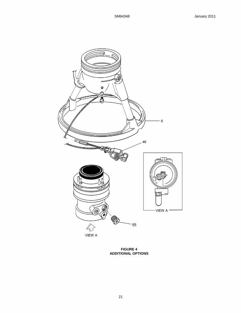
which Screw (23) was removed. Hold the nozzle such that the Tool is below the nozzle and rotate the Quick Disconnect Adapter (49, 50, 56, 59, or 64), Ball Valve (62) or Regulator (47) until all Balls (11) have been captured in the Tool. The correct amount of Balls (11) will be captured when the level of Balls (11) reaches the line scribed on the tube of the Tool. If the Tool is not utilized, remove Balls (11), 39 each, from Unit by hand. Hold bolt hole vertical (pointed down) and allow all ball bearings to fall through the bolt hole. Catch all balls in a container. Some rotation between the Body (9) and the attached Adapter, Ball Valve or Regulator may be required to allow 39 Balls (11) to fall out of hole. Remove the Adapter, Ball Valve or Regulator (refer to appropriate Service Manual). If Clip (12) is to be replaced, use a pair of needle nose pliers to grasp the existing part and pull it from the hole in the Body (9). See Figure 4. Clear the hole of any debris.
Remove O-Ring (25) from internal groove in the inlet of the Body (9). Visually inspect Wear Ring (9A) installed in the internal groove for excessive wear. If it appears to be worn remove for further inspection in section 7.0.
6.3 To remove the Cover (1) it is necessary to remove the appropriate Grips (4) or (6) or the appropriate Handle (8A). If the Cover (1) is in good condition it is not necessary to remove it at this time. Leave it attached to the handle. The Screw (4B) should be removed with a torque wrench and the removal torque measured. This screw is a self-locking type and is designed to be reused several times before losing its locking capability. If the torque
SM64348 January 2011
9
is less than 6.5 in-lbs discard it and replace it during reassembly.
Remove the Bumper (5) only if replacement is necessary by cutting through it.
6.4 Screw (7) is a self locking type screw that utilizes a nylon insert in the threads to affect the resistance required to provide the locking. Self locking screws are designed to be reused several times before losing their locking effectivity. Note that , here again, the older units use the Screw (7) with a screwdriver slot and newer units use one with an Allen head. These Screws (7) are fully interchangeable. Using a torque wrench, remove Screw (7) from Collar Assy (8), measuring the torque during removal. If the torque is less than 9.5 in lbs (0.11 m kg) discard the screw and replace it with a new one during reassembly. Remove the Balls (10) from the bolt hole in the manner described in paragraph 6.2 above. There are 49 balls in this joint. The correct number of Balls (10) will be removed when the level in the Tool reaches the line created by the brass fitting that screws into the Collar (8). If the Tool is not utilized, store the Balls (10) in a separate container for cleaning and replacement later.
6.5 Engage the nozzle to the S204451 flange (any standard aircraft three-lug locking flange).
6.6 Remove Collar Assy (8) from Body (9) by aligning the groove in the Collar Assy (8) with detent on Body (9) and pull Body (9) from Collar Assy.
6.7 Remove S204451 Adapter.
6.8 Turn Lever (14) to open Poppet (15).
6.9 Remove Cotter Pin (26) and unscrew the Poppet Assy (15) from the Shaft (32). Older nozzles had a flow diverting shroud present that was pressed into place. If it is present and firmly in place, leave it in place. If it is loose, remove it completely and discard it. It is no longer needed. Refer to Figure 6 for location and identification of the shroud.
6.10 The Nozzle Seal Assembly (40) may be removed by lifting off Body (9). The Plate (42) may be removed from the Seal (43) by spreading the ends of the Retaining Ring (43), removing it from the groove in the Seal (43) and then sliding the Plate (42) off the Seal (43).
6.11 The three Lock Pins (19), three Lock Pin Springs (20), three Index Pins (21) and O-Ring (18) may now be removed.
6.12 Hold the nozzle outlet in an “up” position as you would if the aircraft adapter were underwing. View Lever (14) to determine the age of the lever. Two older versions, both gray in color, were produced, one with an operating lever that
is clocked in the 6 o’clock position when closed and the other with the handle clocked in the 3 o’clock position when closed. The newer lever is black, clocked at 6 o’clock and is retained by a single screw through the middle of the lever. Note: If a gray handle retained by a single screw is present replace it with a new black handle. Proceed to 6.12.1 if the older handles are present, other wise proceed to 6.13.
6.12.1 If either older lever is present, hold the Body (9) with the outlet in an upward position. Rotate it until the two pipe Plugs (22) are visible. Remove the left hand plug. If the newer black lever is present move on to 6.13.
6.12.2 Remove Screws (35) through plug opening using a torque wrench. The torque to remove the Screws (35) shall not be less than 1.5 in.-lbs. If it is less than that discard and replace the Screws (35). Observe the orientation of the Plate (36) with respect to the Lever (14) such that it can be duplicated during reassembly. Mis-orientation will result in not being able to close the nozzle properly.
6.13 On nozzles with a black colored handle, serial number 6520 and subsequent, the handle is retained by a single screw located through the center of the Lever (14). There is no need to remove either of the Plugs (22) unless a leak has been observed. Proceed to 6.14 if the black handle is present.
6.14 Remove Screw (39), Washer (40) and O-ring (41) from the center of the Lever (14). Discard Screw (39) and O-ring (41). Pull Lever (14) from Body (9). Remove Seal (37) and Backup Ring (38) from Lever (14). Discard Seal (37) and Backup Ring (38). Proceed to 6.15.
6.15 On nozzles with older handles proceed to 6.15.1. On nozzles with the newer handles skip to 6.15.2.
6.15.1 Remove assembled Shaft (32), Pin (33), Link (34) and Plate (36) with attaching parts from Body (9). Remove Pin (33). Disassemble Cotter Pin (29), Nut (30) and Crank Pin (31) only if replacement is necessary. (Note that older links will be red in color while the newer ones will be natural stainless steel. Both are acceptable for use.)
6.15.2 Remove assembled Shaft (32), Pin (33), Link (34) and Crank (36) with attaching parts from Body (9). Disassemble Cotter Pin (29), Nut (30), Crank Pin (29), Wave Washers (28) from Link (34) and Crank (36) only if replacement is necessary. Discard Wave Washers (28).
6.16 Remove Pin (33). Disassemble Cotter Pin (29), Nut (30) and Crank Pin (31) only if replacement is necessary.
SM64348 January 2011
10
6.17 Do not remove Cable (44), option D only, unless replacement is required. The mounting screw is included with the new replacement assembly.
6.18 On option E - remove the Vacuum Breaker (53) only if replacement is required. The
Vacuum Breaker (53) is not economical to repair and should be replaced, if needed, as a complete assembly. Attempts to repair this unit may result in fuel spills.
7.0 INSPECTION
It is recommended that all O-rings (18), (24), (37) and (25), Back-up (38), Nose Seal (43) & Cotter Pins (26) & (29) (if it is disassembled) be replaced upon every overhaul. Note: Be sure to order the correct O-ring (24) for the Screw (23) present. If a kit is being used, it will contain both O-rings (24), use the appropriate one and discard the other. Inspect all metal parts for dings, gouges, abrasions, etc. Use 320 grit paper to smooth and remove sharp edges. Replace any part with damage exceeding 15% of local wall thickness. Use alodine 1200 to touch up bared aluminum. Precisely measure the following items. Replace any part that exceeds the identified maximum or minimum wear limits:
Both holes in item 34 Link (.196 inch (4.98 mm) diameter max. & .320 inch (8.13 mm) diameter max.).
Bearing diameter of item 31 Pin (.300 inch (7.62 mm) diameter min).
Tapered bearing diameter of item 14 Lever (.697 inch (17.7 mm) diameter min on large end & .635 inch (16.1 mm) diameter min on small end).
Measure diameter of the three round holes in Plate (42). If holes are elongated or exceed 0.222 inches (5.639 mm) the Plate (42) should be replaced. Measure the width and diameter of the other three holes. If the diameter exceeds 0.330 (8.382 mm) or the width across the flats exceeds 0.253 inches (6.426 mm), the Plate (42) should be replaced.
On older nozzles without a wear ring in the body, check the ball race [internal groove that mates the Balls (10)] inside the Body (9) for raised burrs or buildup of material that may prevent the disassembly of the mating Adapter. The corner of the ball race should be a smooth radius no greater than .03 inches (.76 mm). The raised burr may be removed with appropriate abrasive. If it is too large to remove in this manner, replace the body.
On newer nozzles with the wear ring in the body, if worn remove for inspection. Measure the smallest diameter and if less than 0.075 replace it.
Check the ball race located inside the Collar Assy (8) for raised burrs in the same manner as above.
Check the external ball race on the large OD of the Body (9) in the same manner as above.
Roll Pin (21) on a flat surface to check for straightness. Replace any suspect pin.
Examine the Lever (14) for cracks. On newer nozzles, also examine the fit between the Lever (14) “teeth” and the Crank (36) “teeth” by placing the two parts together and attempting to rotate them against each other. The fit should be snug and not loose. Replace both parts if looseness appears to be present. Do not replace only one part.
8.0 REASSEMBLY
8.1 Reassemble in reverse order of disassembly (Refer to Figure 2 or 3 depending upon the version of nozzle), observing the following:
8.1.1 Make certain all components are clean and free from oil, grease, or any other corrosion resistant compound on all interior or exterior surfaces. Wash all parts with cleaning solvent and dry thoroughly with a clean, lint-free cloth or compressed air.
WARNING:
Use cleaning solvent in a well-ventilated area. Avoid breathing of fumes and excessive solvent contact with skin. Keep away from open flame
DO NOT use any form of grease on Balls (10) or (11) and be certain to install proper number of balls in each hole of Body (9) and collar assembly. The use of Tool 61607 will facilitate the counting and assembly of the Balls (10 or 11) back into the unit. Also make sure that Clip (12) is installed properly to maintain continuity
SM64348 January 2011
11
through the unit. Refer to Figure 4 for installation information.
NOTE: A light coat of petroleum jelly can be applied to all o-rings, springs, and screws for ease of installation.
8.1.2 If Cotter (29) and Nut (30) were removed during disassembly, torque Nut (30) to 80 - 125 in lbs to align slots in nut with hole in Crank Pin (31). When reinserting the sub-assembled parts noted in Para. 6.16 of the disassembly procedure, through the inlet end of the Body (9), ensure that the Shaft (32) is inserted into the Body's (9) axial guide bore far enough that the bore contains the Dowel Pin (33).
On nozzles with the older levers (Figure 3), assure that the orientation of the Plate (36) to the Lever (14) is as observed prior to disassembly. Wave Washers (28) are not used on these nozzles with Plate (36). Use the 9/64 inch Allen wrench through the Body's (9) pipe thread port to secure the Plate (36) to the end of the Lever (14) shaft with the four socket head Screws (35). Torque each of the Screws (35) to 16 to 18 inch pounds above the torque required to rotate the screws in the thread locking inserts installed in the Lever (14) end.
Reinstall the Plug (22). NOTE: Plug (22) when purchased from Carter includes a sealant and the use of Teflon tape is not required. If new Teflon tape is used on reinstallation. Do not utilize more than 1 1/2 wraps of tape. Excessive use of tape could lead to the cracking of the Body (9).
On nozzles with the newer levers the orientation of the Crank (36) is not critical at this point since it will be aligned with the Lever (14). Install Backup Ring (37) and O-ring (38) onto Lever (14) and insert into Body (9). Lever (14) should be aligned with Crank (36) to result in the Lever (14) being at the 9 o’clock position when in the closed position (3 o’clock when opened). The “teeth” in both parts should mesh during the assembly. Place Washer (40), O-ring (41) onto Screw (39) and insert into hole in center of Lever (14). Torque the Screw (39) in the outer portion of the Lever (14) to 125 ± 5 inch pounds, loosen the Screw (39) and retorque to 125 ± 5 inch pounds.
8.1.3 Should it be desired to be able to change the nose seal of the nozzle without a major disassembly of the unit it is possible to do so by eliminating Snap Ring (43). One word of caution should this be done. If the nozzle is opened with a tool that does not have the characteristic lugs of an adapter, the nose seal may follow the poppet open and be difficult to reinstall without disassembly. The Snap Ring (43) will continue to be installed by the factory. When the nose seal is to be replaced, please
refer to the Caution Note in paragraph 6.9.1 before proceeding.
8.1.4 Connect nozzle to S204451 flange when installing the Poppet (15). Use the Lever (14) and move the Shaft (32) to its fully extended (open) position to install the Poppet Assy (15).
Before inserting the Cotter (26), adjust the Poppet Assy (15) using the following instructions:
Use Poppet Adjustment Gauge, 64000, to facilitate the adjustment of the Poppet (15) onto the Shaft (32). Follow instructions furnished with the gauge. If the gauge is not used, place a straight edge across the center of the elastomer lip of the Seal (43). Use feeler gages to measure the average dimension between the bottom of the straight edge and the Poppet (15) face. This dimension should be .070 to .110 inch (1.8 to 2.8 mm). If it is not, calculate the required poppet dimension as follows: (one quarter (1/4) turn of the Poppet (15) axially displaces the Poppet (15) face about .020 inch (0.51 mm).
A. If the feeler gage measurement is too long, prepare to unscrew (loosen) the Poppet (15) one quarter (1/4) turn for each .020 (0.51 mm) inch of required adjustment.
B. If the measurement is too short, prepare to tighten the Poppet (15) one quarter (1/4) turn for each .020 (0.51 mm) inch of required adjustment.
8.15 Once the proper Poppet Assy (15) adjustment is made, rotate the Poppet toward the tightening direction until the next slot in the Poppet Assy (15) is in line with the hole in the Shaft (32). Insert the Cotter (26) and bend over the ends to retain in place in accordance with Figure 5. Note it is important that the correct length of Cotter Pin (26) is utilized for the assembly.
8.2 If the Grip (4) or (6) requires replacing due to wear or the replacement of the Cover (1), the new Grips (4) or (6) shall be reinstalled.
8.3 If Bumper (5) is to be replaced onto Collar Assy (8) warm Bumper (5) in water at 160-180° F to soften before pressing onto Collar Assy (8) .
8.4 If stick Handles (8A) were removed for replacement they should be reassembled to Collar (8) using the appropriate Screws (8B), Washers (8C) and Nuts (8D). Tighten to secure Handles (8A) into place in the Collar (8).
8.5 CRITICAL ASSEMBLY NOTE: Where applicable on assembly of an accessory to this nozzle, the following torquing sequence and
SM64348 January 2011
12
values for the mating to the nozzle should be used:
8.5.1 The six screws accompanying the accessory should be torqued to 75-79 in-lbs. (8.5-9 N-m). Tighten all screws to bottom the heads against the flange without over tightening.
8.5.2 Then start with one screw, mentally numbered “1” working in a clock-wise pattern, tightening approximately to half of the end torque values above. Skip across to screw “4” followed by “6:, “2”, “5” and finally “3”.
8.5.3 Repeat the tightening at the final torque value above in the same pattern.
SM64348 January 2011
13
9.0 TEST
9.1 The following test procedures will be accomplished after overhaul:
9.2 Test conditions
Test media shall JP-4, Jet A or odorless kerosene, commercial solvent 140.
9.3 Functional Test
9.3.1 The nozzle shall be inserted and locked into a test adapter, Carter 6958CG or CH or equivalent and the nozzle valve actuated by use of the crank Lever (14) from the fully closed to fully open position a minimum of five
times. There shall be no evidence of binding or excessive force required for valve actuation.
9.4 Leakage Test
9.4.1 With the nozzle outlet in the normal open position, and the test adapter outlet closed, pressurize the inlet to five PSIG and hold for one minute minimum. There shall be no evidence of external leakage from the nozzle.
9.4.2 Repeat the leakage test at 60 PSIG and 120 PSIG.
9.4.3 Close and disengage the nozzle and repeat 9.4.1 and 9.4.2.
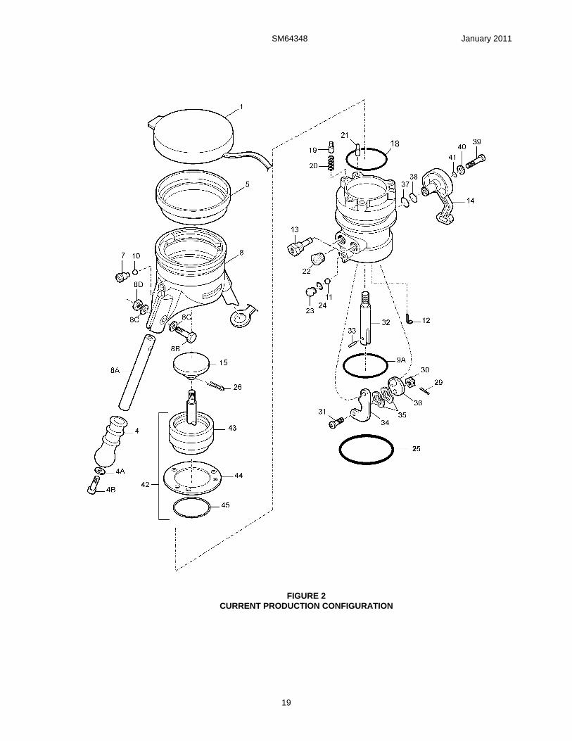
10.0 ILLUSTRATED PARTS CATALOG
Table 1.0 tabulates the parts and sub-assemblies comprising the 64348 Pressure Fueling Nozzle. The item numbers of the table are keyed to the exploded views of the nozzle diagrammed in Figures 1 thru 5.
TABLE 1.0 Current Production Version
Fig. Item Part Number Description Units/ Assy
Nozzle Option
Spares/10 Units/yr.
2 1 207799 Cover .......................................................... 1 All 5
2 Left intentionally blank
3 Left intentionally blank
4 207808 Grip............................................................. 2 All but U 5
4A GF960-516 Washer ....................................................... 2 All 5
4B GF16997-78L Cap Screw .................................................. 2 All 5
5 23622 Bumper ....................................................... 1 All 3
4 6 207816 Circular Handle ........................................... 1 U 2
2 7 220484 Screw, Pan Head (Note 10) ........................ 1 All -
8 220269 Collar .......................................................... 1 All -
8A 210600 Handle ........................................................ 2 All -
8B GF4-13A Screw.......................................................... 2 All -
8C GF960-416 Washer ....................................................... 2 All -
8D GF21042-4 Nut .............................................................. 2 All -
9 207784 Body (Replaced by 47375).......................... 1 All -
47375 Body Assembly (on newer nozzles) ............ 1 All -
221341 Body (not available as a spare part - order 47375 only)...................................
1
All
-
9A 220893 Wear Ring (newer nozzles) (Note 10) 1 All -
10 221075 Bearing, Ball ............................................... 49 All -
11 221075 Bearing, Ball ............................................... 39 All -
12 209853 Clip ............................................................. 1 All 1
13 Left intentionally blank
14 220878-1 On/Off Act. Lever (New Lever) (Note 11).... 1 All -
15 210593 Poppet ........................................................ 1 All -
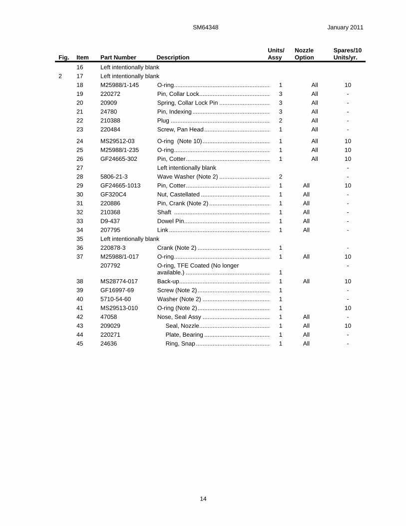
SM64348 January 2011
14
Fig. Item Part Number Description Units/ Assy
Nozzle Option
Spares/10 Units/yr.
16 Left intentionally blank
2 17 Left intentionally blank
18 M25988/1-145 O-ring.......................................................... 1 All 10
19 220272 Pin, Collar Lock........................................... 3 All -
20 20909 Spring, Collar Lock Pin ............................... 3 All -
21 24780 Pin, Indexing ............................................... 3 All -
22 210388 Plug ............................................................ 2 All -
23 220484 Screw, Pan Head........................................ 1 All -
24 MS29512-03 O-ring (Note 10)......................................... 1 All 10
25 M25988/1-235 O-ring.......................................................... 1 All 10
26 GF24665-302 Pin, Cotter................................................... 1 All 10
27 Left intentionally blank -
28 5806-21-3 Wave Washer (Note 2) ............................... 2 -
29 GF24665-1013 Pin, Cotter................................................... 1 All 10
30 GF320C4 Nut, Castellated .......................................... 1 All -
31 220886 Pin, Crank (Note 2) ..................................... 1 All -
32 210368 Shaft .......................................................... 1 All -
33 D9-437 Dowel Pin.................................................... 1 All -
34 207795 Link ............................................................. 1 All -
35 Left intentionally blank
36 220878-3 Crank (Note 2) ............................................ 1 -
37 M25988/1-017 O-ring.......................................................... 1 All 10
207792 O-ring, TFE Coated (No longer available.) ...................................................
1
-
38 MS28774-017 Back-up....................................................... 1 All 10
39 GF16997-69 Screw (Note 2)............................................ 1 -
40 5710-54-60 Washer (Note 2) ......................................... 1 -
41 MS29513-010 O-ring (Note 2)............................................ 1 10
42 47058 Nose, Seal Assy ......................................... 1 All -
43 209029 Seal, Nozzle........................................... 1 All 10
44 220271 Plate, Bearing ........................................ 1 All -
45 24636 Ring, Snap............................................. 1 All -
SM64348 January 2011
15
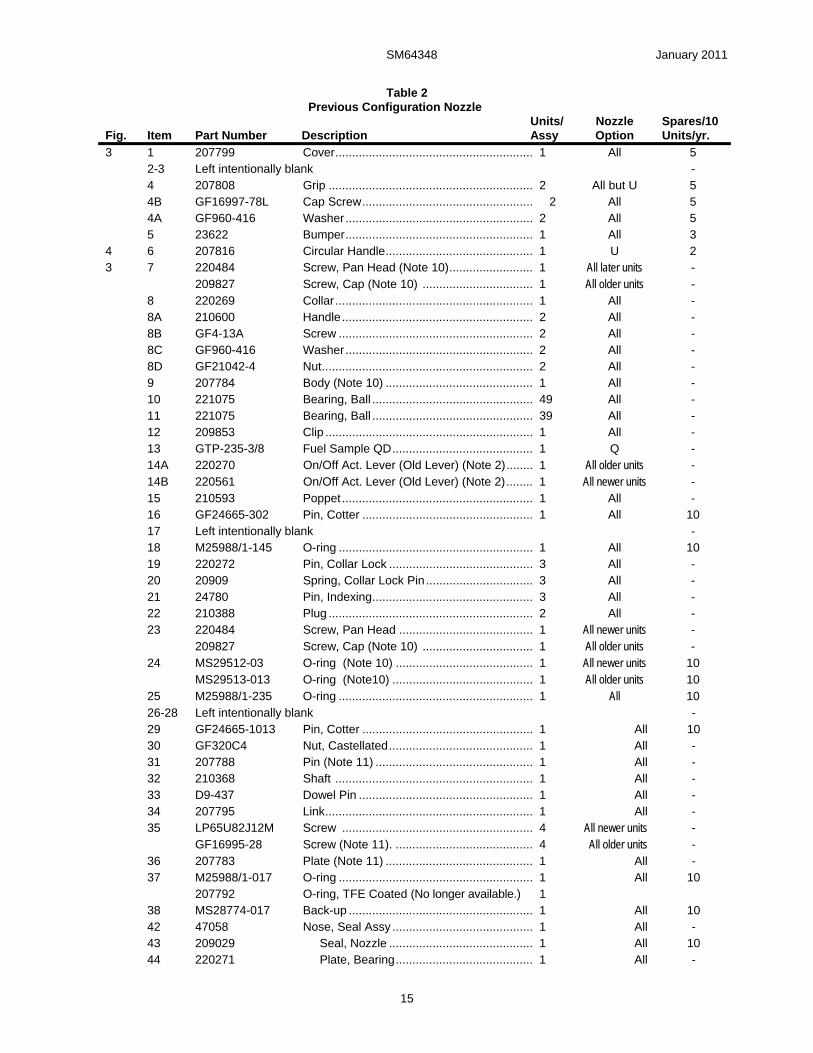
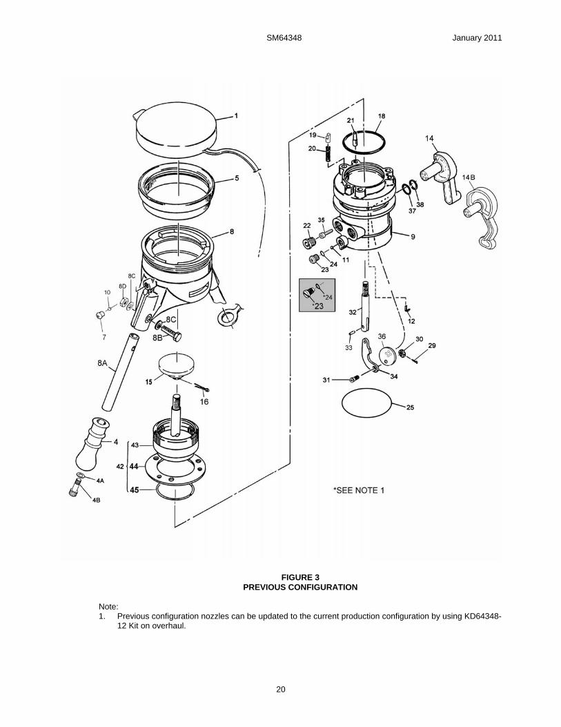
Table 2 Previous Configuration Nozzle
Fig. Item Part Number Description Units/ Assy
Nozzle Option
Spares/10 Units/yr.
3 1 207799 Cover........................................................... 1 All 5 2-3 Left intentionally blank - 4 207808 Grip ............................................................. 2 All but U 5 4B GF16997-78L Cap Screw................................................... 2 All 5 4A GF960-416 Washer........................................................ 2 All 5 5 23622 Bumper........................................................ 1 All 3 4 6 207816 Circular Handle............................................ 1 U 2 3 7 220484 Screw, Pan Head (Note 10)......................... 1 All later units - 209827 Screw, Cap (Note 10) ................................. 1 All older units - 8 220269 Collar ........................................................... 1 All - 8A 210600 Handle......................................................... 2 All - 8B GF4-13A Screw .......................................................... 2 All - 8C GF960-416 Washer........................................................ 2 All - 8D GF21042-4 Nut............................................................... 2 All - 9 207784 Body (Note 10) ............................................ 1 All - 10 221075 Bearing, Ball ................................................ 49 All - 11 221075 Bearing, Ball ................................................ 39 All - 12 209853 Clip .............................................................. 1 All - 13 GTP-235-3/8 Fuel Sample QD.......................................... 1 Q - 14A 220270 On/Off Act. Lever (Old Lever) (Note 2)........ 1 All older units - 14B 220561 On/Off Act. Lever (Old Lever) (Note 2)........ 1 All newer units - 15 210593 Poppet......................................................... 1 All - 16 GF24665-302 Pin, Cotter ................................................... 1 All 10 17 Left intentionally blank - 18 M25988/1-145 O-ring .......................................................... 1 All 10 19 220272 Pin, Collar Lock ........................................... 3 All - 20 20909 Spring, Collar Lock Pin................................ 3 All - 21 24780 Pin, Indexing................................................ 3 All - 22 210388 Plug ............................................................. 2 All - 23 220484 Screw, Pan Head ........................................ 1 All newer units - 209827 Screw, Cap (Note 10) ................................. 1 All older units - 24 MS29512-03 O-ring (Note 10) ......................................... 1 All newer units 10 MS29513-013 O-ring (Note10) .......................................... 1 All older units 10 25 M25988/1-235 O-ring .......................................................... 1 All 10 26-28 Left intentionally blank - 29 GF24665-1013 Pin, Cotter ................................................... 1 All 10 30 GF320C4 Nut, Castellated........................................... 1 All - 31 207788 Pin (Note 11) ............................................... 1 All - 32 210368 Shaft ........................................................... 1 All - 33 D9-437 Dowel Pin .................................................... 1 All - 34 207795 Link.............................................................. 1 All - 35 LP65U82J12M Screw ......................................................... 4 All newer units - GF16995-28 Screw (Note 11). ......................................... 4 All older units - 36 207783 Plate (Note 11) ............................................ 1 All - 37 M25988/1-017 O-ring .......................................................... 1 All 10 207792 O-ring, TFE Coated (No longer available.) 1 38 MS28774-017 Back-up ....................................................... 1 All 10 42 47058 Nose, Seal Assy .......................................... 1 All - 43 209029 Seal, Nozzle ........................................... 1 All 10 44 220271 Plate, Bearing......................................... 1 All -
SM64348 January 2011
16
Fig. Item Part Number Description Units/ Assy
Nozzle Option
Spares/10 Units/yr.
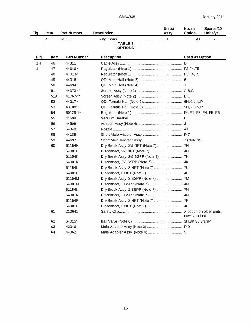
45 24636 Ring, Snap.............................................. 1 All - TABLE 3 OPTIONS
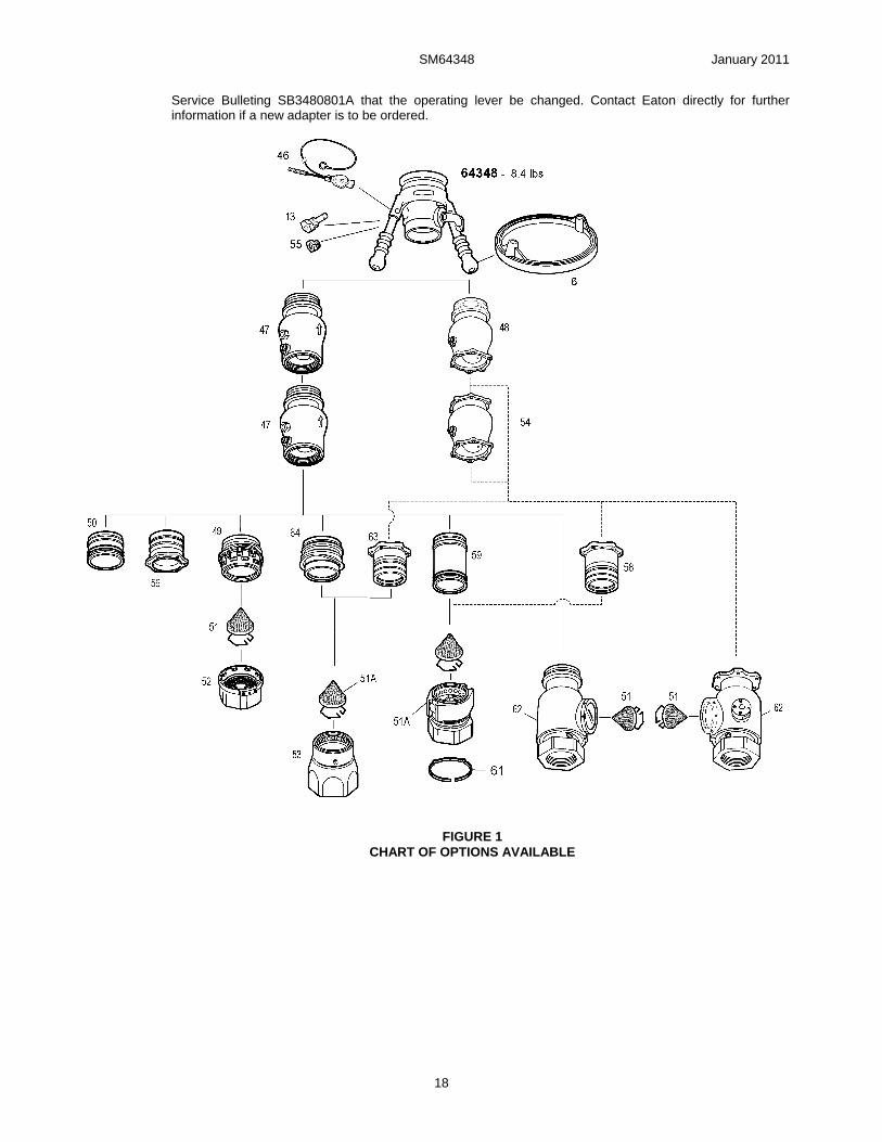
Fig. Item Part Number Description Used as Option
1,4 46 44311 Cable Assy ............................................................ D
1 47 44646-* Regulator (Note 1)................................................. F3,F4,F5
48 47013-* Regulator (Note 1)................................................. F3,F4,F5
49 44316 QD, Male Half (Note 2).......................................... 6
50 44694 QD, Male Half (Note 4).......................................... T
51 44373-** Screen Assy (Note 2) ............................................ A,B,C
51A 41767-** Screen Assy (Note 2) ............................................ B,C
52 44317-* QD, Female Half (Note 2)...................................... 6H,K,L-N,P
53 43108* QD, Female Half (Note 3)...................................... 9H,K,L-N,P
54 60129-1* Regulator (Note 1)................................................. F*, F1, F3, F4, F5, F6
55 41599 Vacuum Breaker ................................................... E
56 44509 Adapter Assy (Note 4) ........................................... J
57 64348 Nozzle ................................................................... All
58 44185 Short Male Adapter Assy ...................................... F*7
59 44697 Short Male Adapter Assy ...................................... 7 (Note 12)
60 61154H Dry Break Assy, 2½ NPT (Note 7)......................... 7H
64001H Disconnect, 2½ NPT (Note 7) ............................... 4H
61154K Dry Break Assy, 2½ BSPP (Note 7) ...................... 7K
64001K Disconnect, 2½ BSPP (Note 7) ............................. 4K
61154L Dry Break Assy, 3 NPT (Note 7) ........................... 7L
64001L Disconnect, 3 NPT (Note 7) .................................. 4L
61154M Dry Break Assy, 3 BSPP (Note 7) ......................... 7M
64001M Disconnect, 3 BSPP (Note 7) ................................ 4M
61154N Dry Break Assy, 2 BSPP (Note 7) ......................... 7N
64001N Disconnect, 2 BSPP (Note 7) ................................ 4N
61154P Dry Break Assy, 2 NPT (Note 7) ........................... 7P
64001P Disconnect, 2 NPT (Note 7) .................................. 4P
61 210641 Safety Clip............................................................. X option on older units, now standard
62 64015* Ball Valve (Note 6) ................................................ 3H,3K,3L,3N,3P
63 43046 Male Adapter Assy (Note 3) .................................. F*9
64 44362 Male Adapter Assy (Note 4) ................................. 9
SM64348 January 2011
17
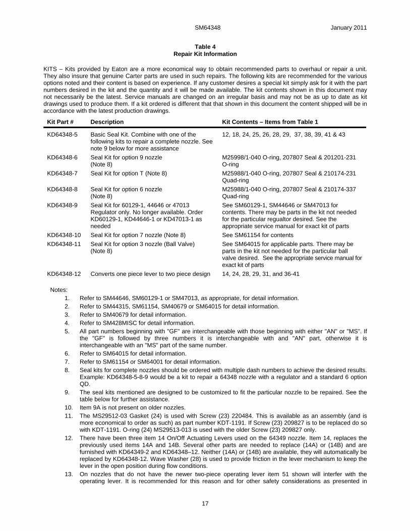
Table 4 Repair Kit Information
KITS – Kits provided by Eaton are a more economical way to obtain recommended parts to overhaul or repair a unit. They also insure that genuine Carter parts are used in such repairs. The following kits are recommended for the various options noted and their content is based on experience. If any customer desires a special kit simply ask for it with the part numbers desired in the kit and the quantity and it will be made available. The kit contents shown in this document may not necessarily be the latest. Service manuals are changed on an irregular basis and may not be as up to date as kit drawings used to produce them. If a kit ordered is different that that shown in this document the content shipped will be in accordance with the latest production drawings.
Kit Part # Description Kit Contents – Items from Table 1
KD64348-5 Basic Seal Kit. Combine with one of the following kits to repair a complete nozzle. See note 9 below for more assistance
12, 18, 24, 25, 26, 28, 29, 37, 38, 39, 41 & 43
KD64348-6 Seal Kit for option 9 nozzle (Note 8)
M25998/1-040 O-ring, 207807 Seal & 201201-231 O-ring
KD64348-7 Seal Kit for option T (Note 8) M25988/1-040 O-ring, 207807 Seal & 210174-231 Quad-ring
KD64348-8 Seal Kit for option 6 nozzle (Note 8)
M25988/1-040 O-ring, 207807 Seal & 210174-337 Quad-ring
KD64348-9 Seal Kit for 60129-1, 44646 or 47013 Regulator only. No longer available. Order KD60129-1, KD44646-1 or KD47013-1 as needed
See SM60129-1, SM44646 or SM47013 for contents. There may be parts in the kit not needed for the particular regualtor desired. See the appropriate service manual for exact kit of parts
KD64348-10 Seal Kit for option 7 nozzle (Note 8) See SM61154 for contents
KD64348-11 Seal Kit for option 3 nozzle (Ball Valve) (Note 8)
See SM64015 for applicable parts. There may be parts in the kit not needed for the particular ball valve desired. See the appropriate service manual for exact kit of parts
KD64348-12 Converts one piece lever to two piece design 14, 24, 28, 29, 31, and 36-41
Notes:
1. Refer to SM44646, SM60129-1 or SM47013, as appropriate, for detail information. 2. Refer to SM44315, SM61154, SM40679 or SM64015 for detail information. 3. Refer to SM40679 for detail information. 4. Refer to SM428MISC for detail information. 5. All part numbers beginning with "GF" are interchangeable with those beginning with either "AN" or "MS". If
the "GF" is followed by three numbers it is interchangeable with and "AN" part, otherwise it is interchangeable with an "MS" part of the same number.
6. Refer to SM64015 for detail information. 7. Refer to SM61154 or SM64001 for detail information. 8. Seal kits for complete nozzles should be ordered with multiple dash numbers to achieve the desired results.
Example: KD64348-5-8-9 would be a kit to repair a 64348 nozzle with a regulator and a standard 6 option QD.
9. The seal kits mentioned are designed to be customized to fit the particular nozzle to be repaired. See the table below for further assistance.
10. Item 9A is not present on older nozzles. 11. The MS29512-03 Gasket (24) is used with Screw (23) 220484. This is available as an assembly (and is
more economical to order as such) as part number KDT-1191. If Screw (23) 209827 is to be replaced do so with KDT-1191. O-ring (24) MS29513-013 is used with the older Screw (23) 209827 only.
12. There have been three item 14 On/Off Actuating Levers used on the 64349 nozzle. Item 14, replaces the previously used items 14A and 14B. Several other parts are needed to replace (14A) or (14B) and are furnished with KD64349-2 and KD64348–12. Neither (14A) or (14B) are available, they will automatically be replaced by KD64348-12. Wave Washer (28) is used to provide friction in the lever mechanism to keep the lever in the open position during flow conditions.
13. On nozzles that do not have the newer two-piece operating lever item 51 shown will interfer with the operating lever. It is recommended for this reason and for other safety considerations as presented in
SM64348 January 2011
18
Service Bulleting SB3480801A that the operating lever be changed. Contact Eaton directly for further information if a new adapter is to be ordered.
FIGURE 1 CHART OF OPTIONS AVAILABLE
SM64348 January 2011
19
FIGURE 2 CURRENT PRODUCTION CONFIGURATION
SM64348 January 2011
20
FIGURE 3 PREVIOUS CONFIGURATION
Note: 1. Previous configuration nozzles can be updated to the current production configuration by using KD64348-
12 Kit on overhaul.
SM64348 January 2011
21
FIGURE 4 ADDITIONAL OPTIONS
SM64348 January 2011
22
FIGURE 5
CONTINUITY CLIP INSTALLATION
SM64348 January 2011
23
FIGURE 6 POPPET-SHAFT RETENTION

Aerospace Group Conveyance Systems Division 9650 Jeronimo Road Irvine, CA USA 926218 Ph: (949) 452-9500 Fax: (949) 452-9992