Embed Size (px)
Citation preview
www.
195 West Ryan RoadOak Creek, WI 53154
elwood.com/fluidpower.html
PRESSURE CONTROL VALVE
Features
• Simple, compact design consisting of top plate and body.
• Easily convert from relief to reducer or re-ducer to relief.
• Designed for either SAE flange or manifold mounting.
• All parts replaceable; reversible seat design for additional service life.
• Heat treated stainless steel internals.• Standard adjustable orifice restrictor on all
valves.• Internal and external pilot feeds, drains, and
gages connections located for flexibility and easy maintenance.
• Proportional pressure control option in-cludes pilot head with proportional force controlled solenoid.
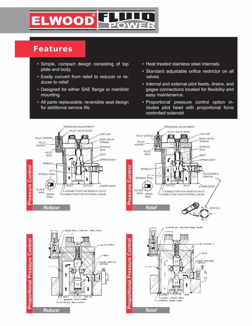
TOP CAP
MAIN VALVE SPRING
SPINDLESEAL
SEAT
UPPER BODY
PILOT SPRING
PILOTPOPPET
PILOT SEAL
SPINDLE
SPINDLE SEAL
OUTLET INLET
CONNECTION FOR REMOTE PILOTCONNECTION FOR EXTERNAL DRAIN
OUTER RING INNER
RING
LOWER BODY
PILOT VALVE BODY
PRESSURE ADJUSTMENT
ADJUSTABLEORIFICE
No. 4
No. 1No. 2
No. 3
ORIFICE
TOP CAP
MAIN VALVE SPRING
SPINDLESEAL
SEAT
UPPER BODY
PILOT SPRING
PILOTPOPPET
PILOT SEAL
SPINDLE
SPINDLE SEAL
INLET OUTLET
CONNECTION FOR REMOTE PILOTCONNECTION FOR EXTERNAL DRAIN
OUTER RING
INNERRING
LOWER BODY
PILOT VALVE BODY
PRESSURE ADJUSTMENT
Pres
sure
Con
trol
Prop
ortio
nal P
ress
ure
Con
trol
Prop
ortio
nal P
ress
ure
Con
trol
Pres
sure
Con
trol
Reducer
Reducer Relief
Relief
www.
195 West Ryan RoadOak Creek, WI 53154
elwood.com/fluidpower.html
Operation & Functionality
Proportional Pressure Control• Set system pressure using an electronic am-
plifier card, or adaptive control module. - Available in Open Loop or Closed Loop - Used with Pressure Transducer - Closed Loop used for extreme accuracy.
• System pressure is adjusted in relation to a current signal to the proportional solenoid.
• Pressure balance on the main spindle allows the spring to hold the valve in a closed posi-tion, for relief, and open for reducing.
• When system pressure working on the pilot poppet exceeds the solenoid force, pilot flow is established to the external drain.
• The adjustable orifice plug allows a pre-pres-sure drop to occur in the valve allowing the main spindle to create a larger opening in the sealing area, adding to the life of the valve.
Non-Proportional Pressure Control• Set system pressure by adjusting the pilot
relief control valve.• Pressure balance on the main spindle al-
lows the spring to hold the valve in a closed position, for relief, and open for reducing.
• When system pressure working on the pilot poppet exceeds the set pilot relief adjust-ment, pilot flow is established to the external drain.
• The adjustable orifice plug allows a pre-pres-sure drop to occur in the valve allowing the main spindle to create a larger opening in the sealing area, adding to the life of the valve.
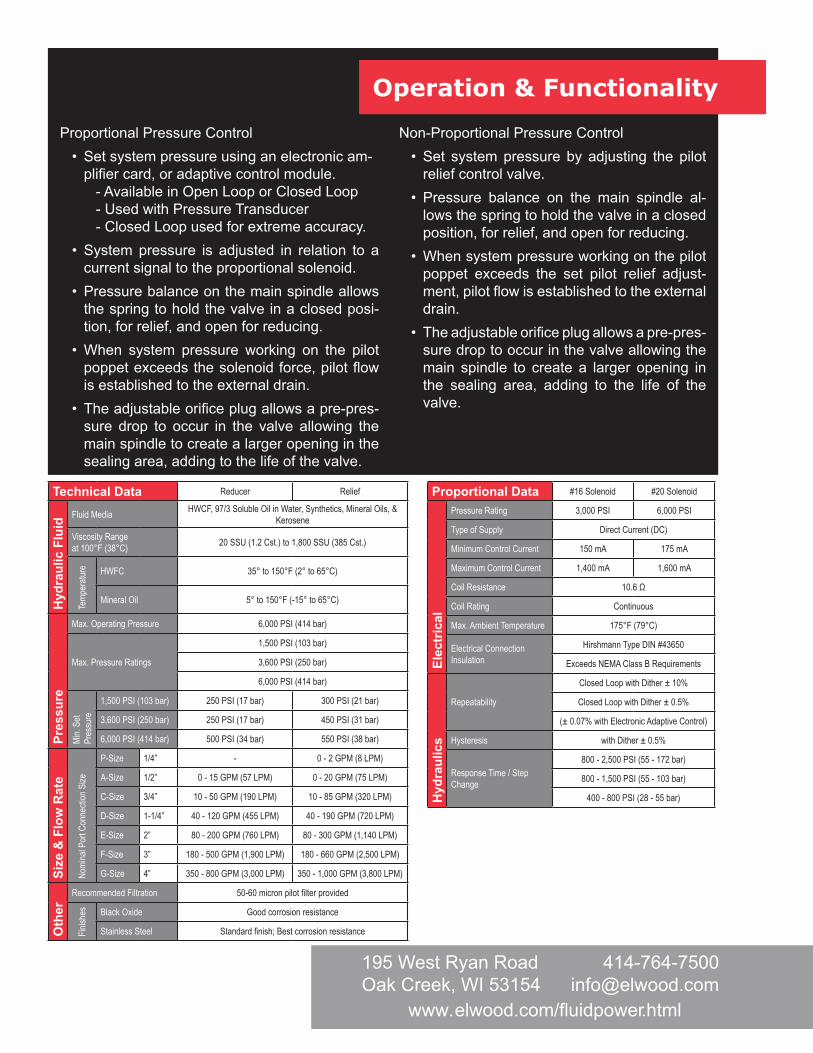
Technical Data Reducer Relief
Hyd
raul
ic F
luid
Fluid Media HWCF, 97/3 Soluble Oil in Water, Synthetics, Mineral Oils, & Kerosene
Viscosity Range at 100°F (38°C) 20 SSU (1.2 Cst.) to 1,800 SSU (385 Cst.)
Temp
eratu
re HWFC 35° to 150°F (2° to 65°C)
Mineral Oil 5° to 150°F (-15° to 65°C)
Pres
sure
Max. Operating Pressure 6,000 PSI (414 bar)
Max. Pressure Ratings
1,500 PSI (103 bar)
3,600 PSI (250 bar)
6,000 PSI (414 bar)
Min.
Set
Pres
sure
1,500 PSI (103 bar) 250 PSI (17 bar) 300 PSI (21 bar)
3,600 PSI (250 bar) 250 PSI (17 bar) 450 PSI (31 bar)
6,000 PSI (414 bar) 500 PSI (34 bar) 550 PSI (38 bar)
Size
& F
low
Rat
e
Nomi
nal P
ort C
onne
ction
Size
P-Size 1/4” - 0 - 2 GPM (8 LPM)
A-Size 1/2” 0 - 15 GPM (57 LPM) 0 - 20 GPM (75 LPM)
C-Size 3/4” 10 - 50 GPM (190 LPM) 10 - 85 GPM (320 LPM)
D-Size 1-1/4” 40 - 120 GPM (455 LPM) 40 - 190 GPM (720 LPM)
E-Size 2” 80 - 200 GPM (760 LPM) 80 - 300 GPM (1,140 LPM)
F-Size 3” 180 - 500 GPM (1,900 LPM) 180 - 660 GPM (2,500 LPM)
G-Size 4” 350 - 800 GPM (3,000 LPM) 350 - 1,000 GPM (3,800 LPM)
Oth
er
Recommended Filtration 50-60 micron pilot filter provided
Finish
es Black Oxide Good corrosion resistance
Stainless Steel Standard finish; Best corrosion resistance
Proportional Data #16 Solenoid #20 Solenoid
Elec
tric
al
Pressure Rating 3,000 PSI 6,000 PSI
Type of Supply Direct Current (DC)
Minimum Control Current 150 mA 175 mA
Maximum Control Current 1,400 mA 1,600 mA
Coil Resistance 10.6 Ω
Coil Rating Continuous
Max. Ambient Temperature 175°F (79°C)
Electrical Connection Insulation
Hirshmann Type DIN #43650
Exceeds NEMA Class B Requirements
Hyd
raul
ics
Repeatability
Closed Loop with Dither ± 10%
Closed Loop with Dither ± 0.5%
(± 0.07% with Electronic Adaptive Control)
Hysteresis with Dither ± 0.5%
Response Time / Step Change
800 - 2,500 PSI (55 - 172 bar)
800 - 1,500 PSI (55 - 103 bar)
400 - 800 PSI (28 - 55 bar)
Response Data
Definitions
1. Cracking Pressure - The point the main spindle first begins to open.
2. Response Time - The duration of time from when the set pressure is met as pressure increases, to when the set pressure is met as pressure decreases.
3. Pressure Over-Shoot - The amplitude of the peak pressure over the set pressure of the valve.
4. Recovery - The duration of time from the end of the response time to the stabilization at set pres-sure.
5. Pressure Override - The difference between full flow and cracking pressure.
6. Compound Relief Valve - A relief valve that operates in two (2) stages. The pilot stage contains the pressure-limiting valve; wherein, a poppet is held against the seat by an adjustable spring. The work port connections are made to the main body, and diversions of the full flow volume by the balanced spindle in the main body.
7. Balanced Spindle - During normal operation, this spindle is in hydraulic balance.
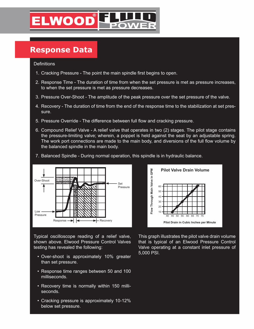
Typical oscilloscope reading of a relief valve, shown above. Elwood Pressure Control Valves testing has revealed the following:
• Over-shoot is approximately 10% greater than set pressure.
• Response time ranges between 50 and 100 milliseconds.
• Recovery time is normally within 150 milli-seconds.
• Cracking pressure is approximately 10-12% below set pressure.
This graph illustrates the pilot valve drain volume that is typical of an Elwood Pressure Control Valve operating at a constant inlet pressure of 5,000 PSI.
Over-Shoot
LowPressure
Response Recovery
SetPressure
Pilot Drain in Cubic Inches per Minute
60
Pilot Valve Drain Volume
50
40
30
20
1040 45 50 55 60 65 70 75
Flow
Thr
ough
Mai
n Va
lve
in G
PM
www.
195 West Ryan RoadOak Creek, WI 53154
elwood.com/fluidpower.html
3000 210
2800 191
2600 179
2400 166
2200 150
2000 138
1800 124
1600 109
1400 97
1200 83
1000 68
800 55
600 41
400 27
200 14
0.2 .4 .6 .8 1.0 1.2
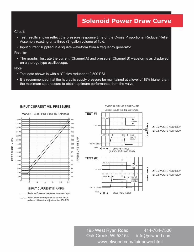
INPUT CURRENT VS. PRESSURE
Model C, 3000 PSI, Size 16 Solenoid
INPUT CURRENT IN AMPS Reducer Pressure response to current input
Relief Pressure response to current input (reflects differential adjustment of 150 PSI
PR
ES
SU
RE
IN P
SI
PR
ES
SU
RE
IN B
AR
Solenoid Power Draw Curve
Circuit:• Test results shown reflect the pressure response time of the C-size Proportional Reducer/Relief
Assembly reacting on a three (3) gallon volume of fluid.• Input current supplied in a square waveform from a frequency generator.
Results:• The graphs illustrate the current (Channel A) and pressure (Channel B) waveforms as displayed
on a storage type oscilloscope.Note:
• Test data shown is with a “C” size reducer at 2,500 PSI.• It is recommended that the hydraulic supply pressure be maintained at a level of 15% higher than
the maximum set pressure to obtain optimum performance from the valve.
A: 0.2 VOLTS / DIVISIONB: 0.5 VOLTS / DIVISION
.334 AMP
.822 AMP
.478 AMP
910 PSI (59 Bar)
19.6 MS
A
B
MSEC. 50 2500 PSIG INLET
TEST #2
.330 AMP
.725 AMP
.395 AMP
17.8 MS 13 MS1530 PSI(99) Bar)
790 PSI (51 Bar)
A
B
MSEC. 50
TYPICAL VALVE RESPONSECurrent Input From Sq. Wave Gen.
2500 PSIG INLET(1.0 VOLTS = 1000 PSIG)
TEST #1
~
14.3 MS1850 PSI(119) Bar)
A: 0.2 VOLTS / DIVISIONB: 0.5 VOLTS / DIVISION
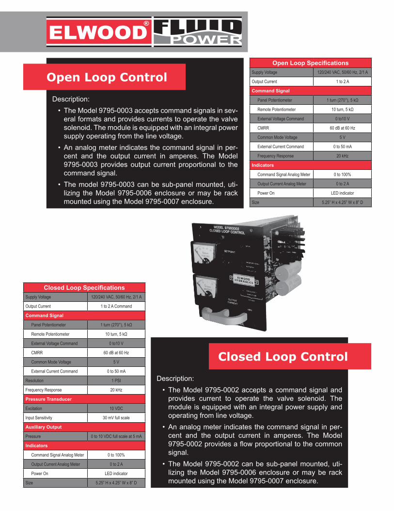
Open Loop Control
Description:• The Model 9795-0003 accepts command signals in sev-
eral formats and provides currents to operate the valve solenoid. The module is equipped with an integral power supply operating from the line voltage.
• An analog meter indicates the command signal in per-cent and the output current in amperes. The Model 9795-0003 provides output current proportional to the command signal.
• The model 9795-0003 can be sub-panel mounted, uti-lizing the Model 9795-0006 enclosure or may be rack mounted using the Model 9795-0007 enclosure.
Closed Loop Control
Description:• The Model 9795-0002 accepts a command signal and
provides current to operate the valve solenoid. The module is equipped with an integral power supply and operating from line voltage.
• An analog meter indicates the command signal in per-cent and the output current in amperes. The Model 9795-0002 provides a flow proportional to the common signal.
• The Model 9795-0002 can be sub-panel mounted, uti-lizing the Model 9795-0006 enclosure or may be rack mounted using the Model 9795-0007 enclosure.
Open Loop SpecificationsSupply Voltage 120/240 VAC, 50/60 Hz, 2/1 A
Output Current 1 to 2 A
Command Signal
Panel Potentiometer 1 turn (270°), 5 kΩ
Remote Potentiometer 10 turn, 5 kΩ
External Voltage Command 0 to10 V
CMRR 60 dB at 60 Hz
Common Mode Voltage 5 V
External Current Command 0 to 50 mA
Frequency Response 20 kHz
Indicators
Command Signal Analog Meter 0 to 100%
Output Current Analog Meter 0 to 2 A
Power On LED indicator
Size 5.25” H x 4.25” W x 8” D
Closed Loop SpecificationsSupply Voltage 120/240 VAC, 50/60 Hz, 2/1 A
Output Current 1 to 2 A Command
Command Signal
Panel Potentiometer 1 turn (270°), 5 kΩ
Remote Potentiometer 10 turn, 5 kΩ
External Voltage Command 0 to10 V
CMRR 60 dB at 60 Hz
Common Mode Voltage 5 V
External Current Command 0 to 50 mA
Resolution 1 PSI
Frequency Response 20 kHz
Pressure Transducer
Excitation 10 VDC
Input Sensitivity 30 mV full scale
Auxiliary Output
Pressure 0 to 10 VDC full scale at 5 mA
Indicators
Command Signal Analog Meter 0 to 100%
Output Current Analog Meter 0 to 2 A
Power On LED indicator
Size 5.25” H x 4.25” W x 8” D
www.
195 West Ryan RoadOak Creek, WI 53154
elwood.com/fluidpower.html
Custom sizes & specifications available upon request.
CRL
ARL
PRL
DRL
ERL
FRL
GRL
CURL
GRD
FRD
DURL
EURL
FURL
GURL
ARD
CRD
DRD
ERD
MODEL
FLOW RANGEDESCRIPTION
P-Size Relief Valve
A-Size Relief Valve
C-Size Relief Valve
D-Size Relief Valve
E-Size Relief Valve
F-Size Relief Valve
G-Size Relief Valve
A-Size Reducing Valve
C-Size Reducing Valve
D-Size Reducing Valve
E-Size Reducing Valve
F-Size Reducing Valve
G-Size Reducing Valve
C-Size Unloading Relief Valve
D-Size Unloading Relief Valve
E-Size Unloading Relief Valve
F-Size Unloading Relief Valve
G-Size Unloading Relief Valve
0 - 2 GPM8 L/MIN
0 - 20 GPM75 L/MIN
10 - 85 GPM320 L/MIN
40 - 190 GPM720 L/MIN
80 - 300 GPM1,140 L/MIN
180 - 660 GPM 2,500 L/MIN
350 - 1,000 GPM3,800 L/MIN
0 - 15 GPM57 L/MIN
10 - 50 GPM190 L/MIN
40 - 120 GPM455 L/MIN
80 - 200 GPM760 L/MIN
180 - 500 GPM1,900 L/MIN
350 - 800 GPM3,000 L/MIN
10 - 50 GPM190 L/MIN
40 - 120 GPM455 L/MIN
80 - 200 GPM760 L/MIN
180 - 500 GPM1,900 L/MIN
350 - 800 GPM3,000 L/MIN
CODE NO.
RELI
EFUN
LOAD
ING
RELI
EFRE
DUCE
RTY
PE
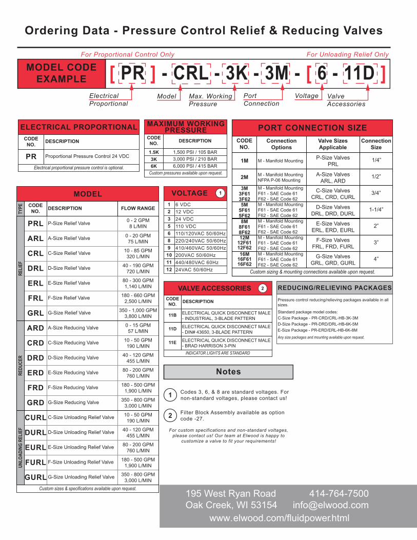
MODEL CODE EXAMPLE [ PR ] - CRL - 3K - 3M - [ 6 - 11D ]
VOLTAGE1235689
101112
6 VDC12 VDC24 VDC110 VDC110/120VAC 50/60Hz220/240VAC 50/60Hz410/460VAC 50/60Hz200VAC 50/60Hz440/480VAC 60Hz24VAC 50/60Hz
1
Ordering Data - Pressure Control Relief & Reducing Valves
For Unloading Relief OnlyFor Proportional Control Only
Max. Working Pressure
PortConnection
Voltage Valve Accessories
ElectricalProportional
MAXIMUM WORKINGPRESSURE
CODE NO.
1.5K3K
1,500 PSI / 105 BAR3,000 PSI / 210 BAR
6K 6,000 PSI / 415 BAR
DESCRIPTION
Custom pressures available upon request.
PORT CONNECTION SIZEConnection
OptionsCODE NO.
1M
2M
3M3F613F625M
5F615F628M
8F618F6212M
12F6112F62
1/4”
1/2”
3/4”
1-1/4”
2”
3”
Connection Size
P-Size ValvesPRL
A-Size ValvesARL, ARD
C-Size ValvesCRL, CRD, CURL
Valve Sizes Applicable
D-Size ValvesDRL, DRD, DURL
E-Size ValvesERL, ERD, EURL
F-Size ValvesFRL, FRD, FURL
16M16F6116F62
4”G-Size ValvesGRL, GRD, GURL
M - Manifold Mounting
M - Manifold MountingNFPA P-06 Mounting
M - Manifold MountingF61 - SAE Code 61F62 - SAE Code 62M - Manifold MountingF61 - SAE Code 61F62 - SAE Code 62M - Manifold MountingF61 - SAE Code 61F62 - SAE Code 62M - Manifold MountingF61 - SAE Code 61F62 - SAE Code 62M - Manifold MountingF61 - SAE Code 61F62 - SAE Code 62
Custom sizing & mounting connections available upon request.
VALVE ACCESSORIESCODE
NO.
ELECTRICAL QUICK DISCONNECT MALE - BRAD HARRISON 3-PIN
ELECTRICAL QUICK DISCONNECT MALE - INDUSTRIAL, 3-BLADE PATTERN
DESCRIPTION
11B
ELECTRICAL QUICK DISCONNECT MALE - DIN# 43650, 3-BLADE PATTERN
11D
11E
INDICATOR LIGHTS ARE STANDARD
2
For custom specifications and non-standard voltages, please contact us! Our team at Elwood is happy to
customize a valve to fit your requirements!
Codes 3, 6, & 8 are standard voltages. For non-standard voltages, please contact us!1
Filter Block Assembly available as option code -27.2
Notes
PR
ELECTRICAL PROPORTIONAL
DESCRIPTION
Proportional Pressure Control 24 VDC
CODE NO.
Electrical proportional pressure control is optional.
REDUCING/RELIEVING PACKAGES
Pressure control reducing/relieving packages available in all sizes.
Standard package model codes:C-Size Package - PR-CRD/CRL-HB-3K-3MD-Size Package - PR-DRD/DRL-HB-6K-5ME-Size Package - PR-ERD/ERL-HB-6K-8M
Any size packages and mounting available upon request.
Model
www.
195 West Ryan RoadOak Creek, WI 53154
elwood.com/fluidpower.html
ELWOOD CORPORATE POLICY STATEMENTIt is the policy of Elwood to provide our customers with products that meet or exceed their
expectations for performance, reliability and safety while ensuring compliance with applicable laws and regulations, and to continually improve all aspects of our business.
C E R T I F I E D C O M PA N Y9001 : 2 0 15
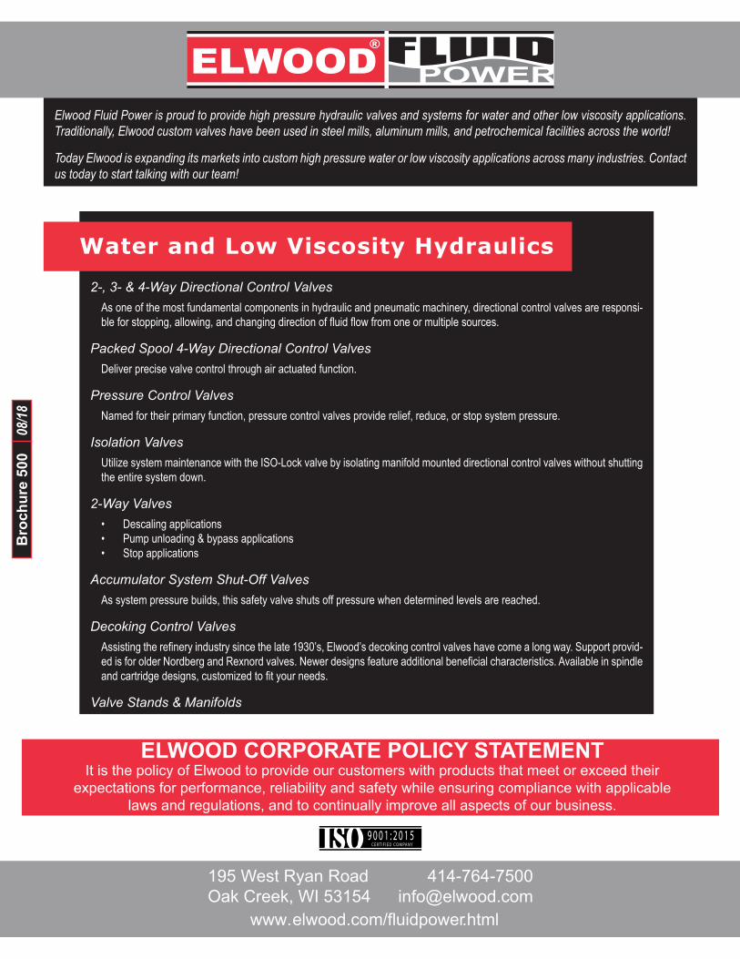
Water and Low Viscosity Hydraulics
2-, 3- & 4-Way Directional Control ValvesAs one of the most fundamental components in hydraulic and pneumatic machinery, directional control valves are responsi-ble for stopping, allowing, and changing direction of fluid flow from one or multiple sources.
Packed Spool 4-Way Directional Control ValvesDeliver precise valve control through air actuated function.
Pressure Control ValvesNamed for their primary function, pressure control valves provide relief, reduce, or stop system pressure.
Isolation ValvesUtilize system maintenance with the ISO-Lock valve by isolating manifold mounted directional control valves without shutting the entire system down.
2-Way Valves• Descaling applications• Pump unloading & bypass applications• Stop applications
Accumulator System Shut-Off ValvesAs system pressure builds, this safety valve shuts off pressure when determined levels are reached.
Decoking Control ValvesAssisting the refinery industry since the late 1930’s, Elwood’s decoking control valves have come a long way. Support provid-ed is for older Nordberg and Rexnord valves. Newer designs feature additional beneficial characteristics. Available in spindle and cartridge designs, customized to fit your needs.
Valve Stands & Manifolds
Elwood Fluid Power is proud to provide high pressure hydraulic valves and systems for water and other low viscosity applications. Traditionally, Elwood custom valves have been used in steel mills, aluminum mills, and petrochemical facilities across the world!
Today Elwood is expanding its markets into custom high pressure water or low viscosity applications across many industries. Contact us today to start talking with our team!
Bro
chur
e 50
008
/18