Embed Size (px)
Citation preview
Press Fit Rework
Project
Project Update
HDPUG Meeting
Düren, Germany 06/05/14
© HDP User Group International, Inc.
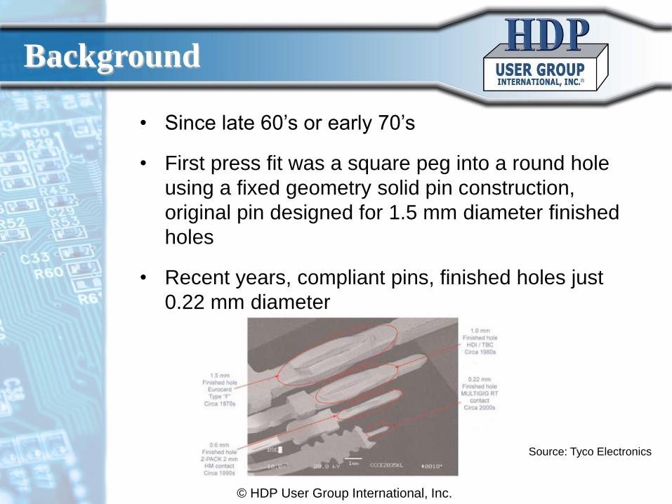
• Since late 60’s or early 70’s
• First press fit was a square peg into a round hole
using a fixed geometry solid pin construction,
original pin designed for 1.5 mm diameter finished
holes
• Recent years, compliant pins, finished holes just
0.22 mm diameter
Source: Tyco Electronics
Background
• When performing press fit component rework, the
plated holes and their annular rings could easily get
damaged. Questions that need to be answered are:
– How much hole wall deformation does one, or several,
rework(s) cause?
– How is the pin insertion force affected by the rework(s)?
– How is the pin retention force affected by the rework(s)?
– Will the gas tight connections be intact?
• There is a need to evaluate press fit component
rework for new components, boards and designs.
© HDP User Group International,
Inc.
Background cont.
Project Goals
• The goal with this project is to understand and to
document how rework affects press fit connection
strength and hole wall deformation for new high-
speed press fit connectors
• 0, 1x, 2x and 3x rework shall be performed on
assemblies with:
– Different, new, high-speed, small pin sizes, connectors
– Three different hole sizes for each component (minimum,
nominal and maximum specified diameters )
– Hole plating, ENIG and ImSn
– Moreover, standard board materials and designs shall be
used
© HDP User Group International,
Inc.
Expected Outcome
• The outcome of this project shall be a document that
specifies how press-fit rework affects
– Pin insertion force
– Pin retention force
– Hole wall deformation
– Gas tight connection
• The project shall tell which pin and design
combinations that work well to rework and what
strength and hole wall deformations that could be
expected
© HDP User Group International,
Inc.
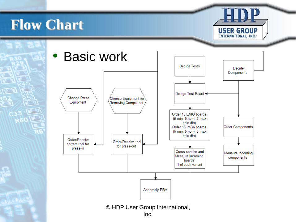
Flow Chart
• Basic work
© HDP User Group International,
Inc.
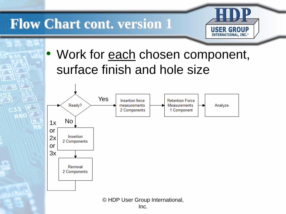
Flow Chart cont. version 1
• Work for each chosen component,
surface finish and hole size
1x
or
2x
or
3x
© HDP User Group International,
Inc.
Yes
No
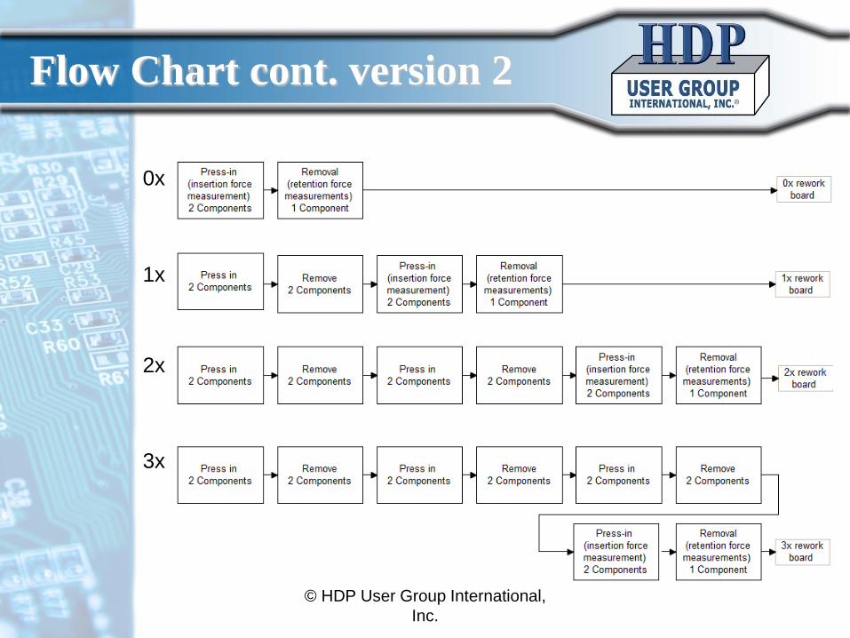
Flow Chart cont. version 2
© HDP User Group International,
Inc.
0x
1x
2x
3x
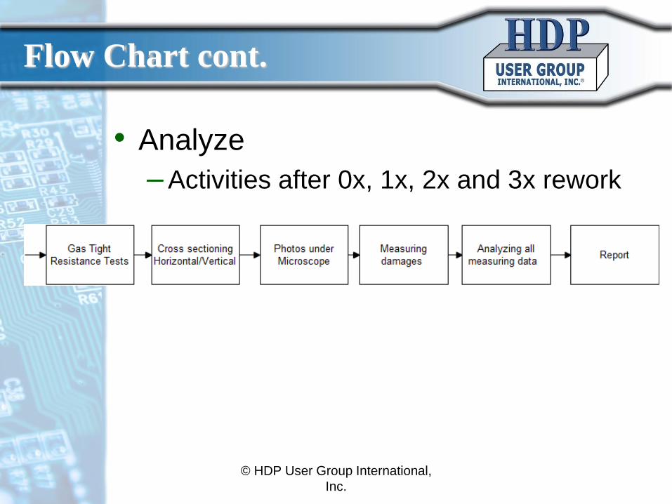
Flow Chart cont.
• Analyze
– Activities after 0x, 1x, 2x and 3x rework
© HDP User Group International,
Inc.
Test Processes
• Initial mechanical measurements of all used materials
• Insertion/Retention test – Demand on retention and insertion force in Telcordia GR-
1217-CORE
• Visual inspection according IPC-001, IPC-610, Telcordia GR-78 R4-10, GR-1217-CORE and IEC 60352-5 (hole deformation, delamination etc.) – Directly after insertion
– After rework
– After retention of pins
• Electrical contact resistance measurements after
aging (gas tight test) shall be performed for all components
© HDP User Group International,
Inc.
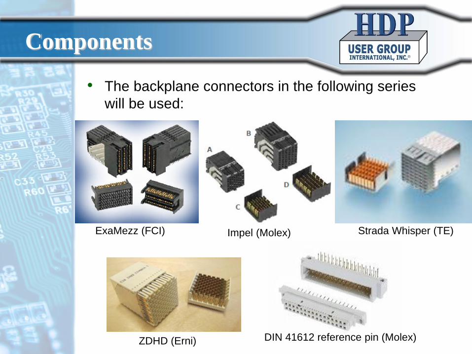
• The backplane connectors in the following series
will be used:
DIN 41612 reference pin (Molex) ZDHD (Erni)
ExaMezz (FCI) Impel (Molex) Strada Whisper (TE)
Components
Operations per Package
• If two different surface finishes are chosen and min,
nom and max hole diameters are used for each
component:
– 20 x 6 = 120 components (a few extra are needed for
incoming inspection and measurement)
• Amount of press-in operations
– 120
• Amount of removals
– 16 x 6 = 96
© HDP User Group International,
Inc.
Need of Boards
• One board for each hole size (min, nom, max)
and surface finish (ENIG, ImSn) is needed for
incoming board hole inspection/measurement – 3 hole sizes and 2 surface finishes give 6 boards
• Four boards are needed for each hole size and
surface finish for the rework test (i.e. for 0x, 1x,
2x and 3x rework) – 4 boards, 2 surface finishes, 3 hole sizes give 24 boards
• Altogether 30 boards are needed
© HDP User Group International,
Inc.
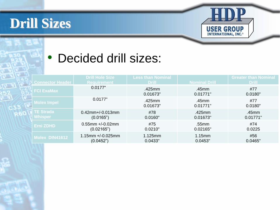
Connector Header Drill Hole Size
Requirement Less than Nominal
Drill Nominal Drill Greater than Nominal
Drill
FCI ExaMax 0.0177" .425mm
0.01673" .45mm
0.01771" #77
0.0180"
Molex Impel 0.0177" .425mm
0.01673" .45mm
0.01771" #77
0.0180"
TE Strada
Whisper 0.42mm+/-0.013mm
(0.0165”) #78
0.0160" .425mm
0.01673" .45mm
0.01771"
Erni ZDHD 0.55mm +/-0.02mm
(0.02165”) #75
0.0210" .55mm
0.02165" #74
0.0225
Molex DIN41612 1.15mm +/-0.025mm
(0.0452”) 1.125mm
0.0433" 1.15mm
0.0453" #56
0.0465"
• Decided drill sizes:
Drill Sizes
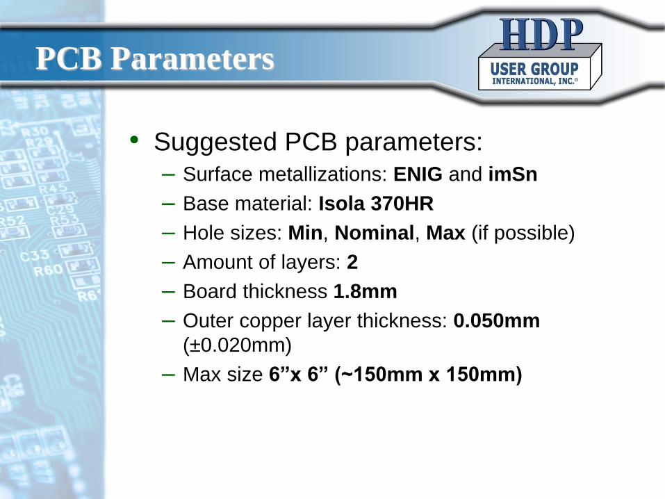
• Suggested PCB parameters:
– Surface metallizations: ENIG and imSn
– Base material: Isola 370HR
– Hole sizes: Min, Nominal, Max (if possible)
– Amount of layers: 2
– Board thickness 1.8mm
– Outer copper layer thickness: 0.050mm
(±0.020mm)
– Max size 6”x 6” (~150mm x 150mm)
PCB Parameters
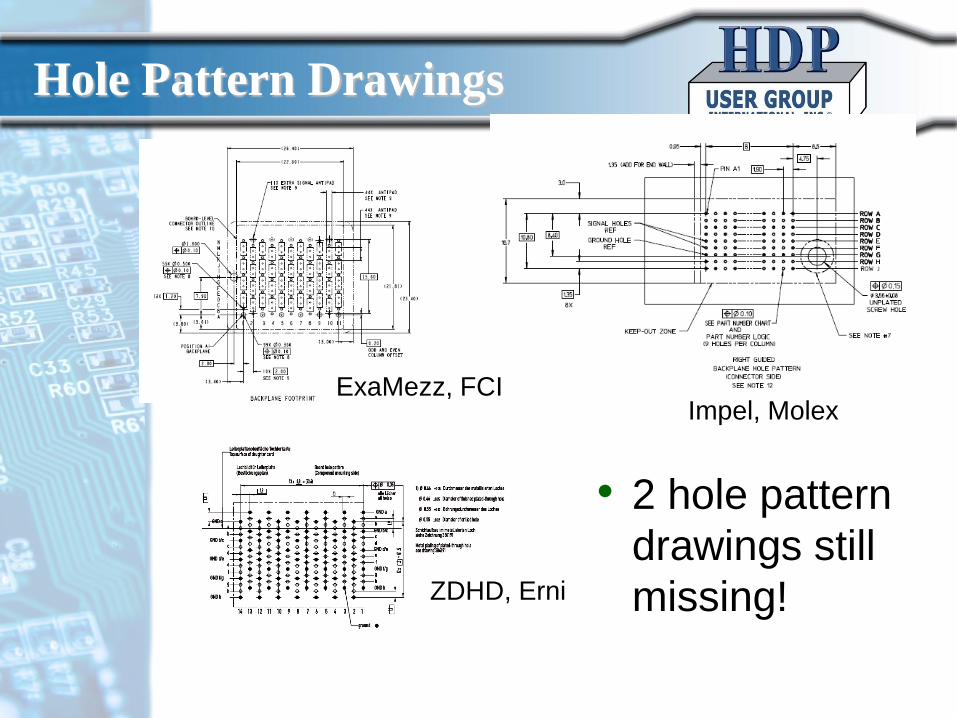
Impel, Molex ExaMezz, FCI
ZDHD, Erni
Hole Pattern Drawings
• 2 hole pattern
drawings still
missing!
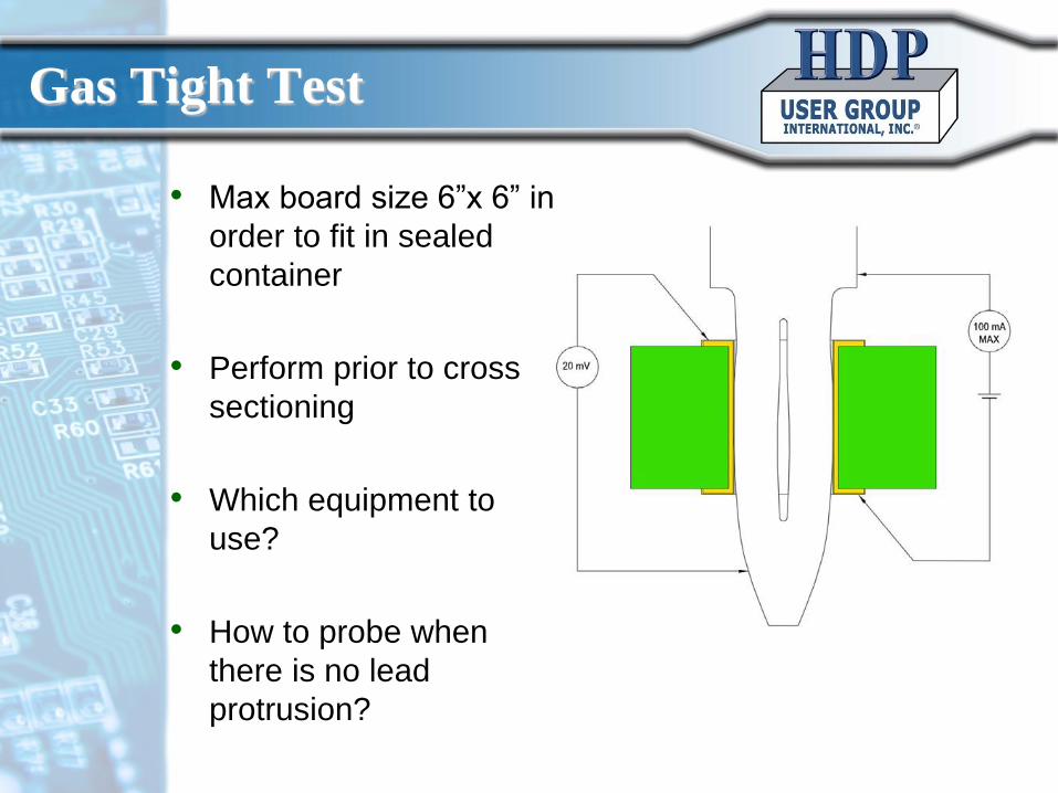
• Max board size 6”x 6” in
order to fit in sealed
container
• Perform prior to cross
sectioning
• Which equipment to
use?
• How to probe when
there is no lead
protrusion?
Gas Tight Test
• Component and hole pattern drawing
for Strada Whisper
• Hole pattern drawing for DIN 41612
Needed in order to be able to design
test board!
Immediate Need
• Preliminary design of test board
– Performed at Ericsson
• Decide how to connect the leads for resistance
measurements for each component type’s gas
tight test
• Decide how to measure retention force after
rework for each component type
– EIA-364, TP05 (used in Molex test)
Next Step
• Order test board
– After agreed design
• Collect all components
– For the actual test there will be a need of at least
120 components of each type
• Collect all needed information about press parameters
and tooling
– Borrow some of the tooling?
– Find suitable site(s) to perform the press fit rework
test
Next Step Cont.
Plans for the Nearest Future
• Last hole pattern drawings and agreement
of all PCB parameters
– June 2014
• Finalized Design of Test Board
– July 2014
• Received all necessary rework information
and tools
– August 2014
• Start assembly and rework tests
– September 2014 © HDP User Group International,
Inc.
Test Questions
• Can we get all the tooling/components?
– Pay for some of the tooling?
– Pay for some of the components?
• Who shall manufacture the test board?
• Where shall the rework tests be performed?
• Who shall do the cross-sectioning?
• Who shall do the analysis?
© HDP User Group International,
Inc.
Team List
• Team List:
• Participating Companies:
– Dell
– Philips
– GE
– Delphi
– Curtis Wright
– PWB Corp
– Nihon Superior
– Ericsson
– Alcatel-Lucent
– Multek
– Cookson
© HDP User Group International, Inc.
– TTM
– Juniper
– ASUS
– Oracle
– Flextronics
– Plexus
– Cisco
– Fujitsu
– Ciena
– Isola
– IBM
– ASE
– Continental
– Panasonic
– Emerson
– IST Group
– Boeing
– Fujitsu
– ZTE
– Sytech
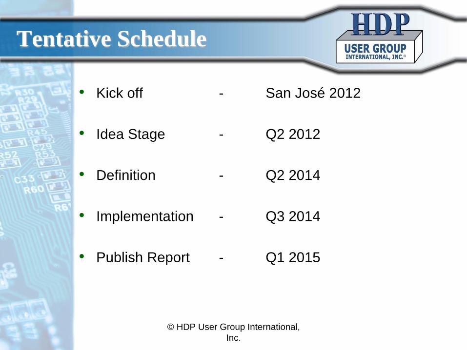
Tentative Schedule
• Kick off - San José 2012
• Idea Stage - Q2 2012
• Definition - Q2 2014
• Implementation - Q3 2014
• Publish Report - Q1 2015
© HDP User Group International,
Inc.