Embed Size (px)
Citation preview

PR/EPR/TEPR20/32/48-M-A/E-S
MARCH, 2000 1 BEGIN SERIAL NO. 00000000
3243 North California Avenue, Chicago, IL 60618
PRESIDENT POPCORN MACHINESERVICE MANUAL
120/208 - 240 Volt, Single and Three Phase, 60 Hz
100/200 Volt Single Phase, 60 Hz
230 Volt, 230/380 Volt Single and Three Phase, 50 Hz
400 Volt, Three Phase, 50 Hz
READ and UNDERSTAND these servicing, and safetyinstructions before servicing this popcorn machine

PR/EPR/TEPR20/32/48-M-A/E-S
MARCH, 2000 2 BEGIN SERIAL NO. 00000000
SAFETY FIRST
The information in this manual is essential for the safe installation andmaintenance of your Cretors popcorn machine. The manual must be readand understood before installing, or maintaining this equipment, orequivalent training must be provided.
"The employer shall instruct each employee in the recognition and avoidanceof unsafe conditions and the regulations applicable to his work environmentto control or eliminate any hazards or other exposure to illness or injury".Ref.: 29 CFR 1926.20 (b)(4)(a)(2)
It is understood that safety rules within individual companies vary. If aconflict exists between the safety procedures contained in this manual andthe rules of a using company, the more stringent rule should takeprecedence.

PR/EPR/TEPR20/32/48-M-A/E-S
MARCH, 2000 3 BEGIN SERIAL NO. 00000000
I INTRODUCTION
This manual is filled with time-saving and money-saving information regarding your Cretorspopcorn machine. There is nothing, however, more important than the safety aids and warningsthat are found throughout this document. The Safety Alert Symbol is used to identify topics ofprimary safety concern wherever they appear. Furthermore, a separate section has been includedwhich deals exclusively with operation and accident prevention.
If, after reviewing this manual, anything is unclear or technical problems are encountered, contactthe dealer from whom you purchased your machine for assistance and if there are any additionalquestions, feel free to contact our Customer Service Department at the address and/or phonenumber listed on the last page of this manual. Always have the model and serial number of yourmachine available to assist in obtaining the correct information.
II SAFETY ALERT SYMBOL
The symbol shown below is used to call your attention to instructions concerning your personalsafety and the safety of others. Watch this symbol. It points out important safety precautions. Itmeans "ATTENTION! Become Alert! Your personal safety is involved!" Read the message thatfollows and be alert to the risk of personal injury or death.
III PURPOSE OF MANUAL
This instruction manual is intended to familiarize owners with the servicingand safety procedures associated with your Cretors popcorn machine.
This manual should be kept available to maintenance personnel.
A person who has not read and understood all operating and safetyinstructions is not qualified to operate the machine.

PR/EPR/TEPR20/32/48-M-A/E-S
MARCH, 2000 4 BEGIN SERIAL NO. 00000000
IV PRODUCT IDENTIFICATION
CRETORS POPCORN MACHINEPRESIDENT Models: PR20E5, PR32E5, PR48E5, EPR20E5, EPR32E5, EPR48E5,TEPR20E6, TEPR32E6, TEPR48E6
ELECTRICAL SPECIFICATIONS: President Models are available in the following Electricalconfigurations:
100/200 Volt, Single Phase, 60 Cycle120/208 Volt, 120/240 Volt, Single and Three Phase, 60 Cycle230 Volt, 230/380 Volts, Single and Three Phase, 50 Cycle
MACHINE SPECIFICATIONS:
MODEL PR20E5 PRESIDENT 20 OZ. ELECTRIC 5' OPEN TOP
Capacity: 20 oz. All-Steel Kettle, 400 one-ounce servings per hour.
Wattage: 5100 watts
Dimensions: 31"D x 60"W x 63" H - - - - 79 cm D x 152 cm W x 160 cm H
Net Weight: 415 lbs. (188 kg)
MODEL PR32E5 PRESIDENT 32 OZ. ELECTRIC 5' OPEN TOP
Capacity: 32 oz. All-Steel Kettle, 640 one-ounce servings per hour
Wattage: 6650 watts
Dimensions: 31"D x 60"W x 63" H - - - - 79 cm D x 152 cm W x 160 cm H
Net Weight: 415 lbs. (188 kg)
MODEL PR48E5 PRESIDENT 48 OZ. ELECTRIC 5' OPEN TOP
Capacity: 48 oz. All-Steel Kettle, 960 one-ounce servings per hour
Wattage: 8200 watts
Dimensions: 31"D x 60"W x 63"H - - - - 79 cm D x 152 cm W x 160 cm H
Net Weight: 415 lbs. (188 kg)
MODEL EPR20E5 PRESIDENT 20 OZ. ELECTRIC 5' ENCLOSED TOP
Capacity: 20 oz. All-Steel Kettle, 400 one-ounce servings per hour
Wattage: 5100 watts
Dimensions: 24"D x 60"W x 73-1/4"H - - - - 61 cm D x 152 cm W x 186 cm H
Net Weight: 425 lbs. (193 kg)

PR/EPR/TEPR20/32/48-M-A/E-S
MARCH, 2000 5 BEGIN SERIAL NO. 00000000
MODEL EPR32E5 PRESIDENT 32 OZ. ELECTRIC 5' ENCLOSED TOP
Capacity: 32 oz. All-Steel Kettle, 640 one-ounce servings per hour
Wattage: 6650 watts
Dimensions: 24"D x 60"W x 73-1/4" H - - - - 61 cm D x 152 cm W x 186 cm H
Net Weight: 425 lbs. (193 kg)
MODEL EPR48E5 PRESIDENT48 OZ. ELECTRIC 5' ENCLOSED TOP
Capacity: 48 oz. All-Steel Kettle 960 one-ounce servings per hour
Wattage: 8200 watts
Dimensions: 24"D x 60"W x 73-1/4" H - - - - 61 cm D x 152 cm W x 186 cm H
Net Weight: 425 lbs. (193 kg)
MODEL TEPR20E6 TWIN PRESIDENT 20 OZ. ELECTRIC 6' ENCLOSED TOP
Capacity: 20 oz. All-Steel Kettles, 400 one-ounce servings per hour, perpopper
Wattage: First popper 5250 watts, second popper 3700 watts
Dimensions: 28"D x 72"W x 73" H - - - - 71 cm D x 182 cm W x 185 cm H
Net Weight: 645 lbs. (293 kg)
MODEL TEPR32E6 TWIN PRESIDENT 32 OZ. ELECTRIC 6' ENCLOSED TOP
Capacity: 2-32oz. All-Steel Kettles , 640 one-ounce servings per hour, perpopper
Wattage: First popper 6800 watts, second popper 5250 watts
Dimensions: 28"D x 72"W x 73" H - - - - 71 cm D x 182 cm W x 185 cm H
Net Weight: 645 lbs. (293 kg)
MODEL TEPR48E6 TWIN PRESIDENT 48 OZ. ELECTRIC 6' ENCLOSED TOP
Capacity: 2-48 oz. All-Steel Kettles, 960 one-ounce servings per hour, perpopper
Wattage: First popper 8350 watts, second popper 6800 watts
Dimensions: 28"D x 72"W x 73" H - - - - 71 cm D x 182 cm W x 185 cm H
Net Weight 645 lbs. ( 293 kg)

PR/EPR/TEPR20/32/48-M-A/E-S
MARCH, 2000 6 BEGIN SERIAL NO. 00000000
VI CONTROL SWITCHES
KETTLE HEAT -Turns the kettle heat On/Off
AGITATOR -Turns the stirrer blade motor On/Off
EXHAUST -Turns exhaust blower On/Off
CORNDITIONER -Turns the cornditioner blower and heat On/Off
LIGHTS -Turns interior lights On/Off
OIL -Provides power to the oil pump
DELIVERY -Initiates the pump cycle
CIRCUIT BREAKER -Push to reset - provides protection to all circuits, except the kettle.
VII INSTALLATION INSTRUCTIONS1. Location
Choose a location for your Cretors popcorn machine to maximize the ease of operation andmaintenance procedures. Check your local building and fire codes for location restrictions.
2. Power Supply
A. Check the nameplate to determine the required power supply.
Connect your popcorn popper only to the correct power source. Failure to do so mayresult in personal injury or death and may damage your popper.
B. C. Cretors and Company recommends dedicated circuits for the President model popcornmachine. The President model poppers require a dedicated circuit to avoid voltage dropin the supply wiring. Check your local electrical codes regarding fuse or circuit breakerrequirements.
Make certain your popcorn machine is properly grounded. Failure to do so may resultin damage to your equipment or present a shock hazard.
3. Connecting Machine to Power Supply
A. Perform work only on de-energized circuits. Failure to do so may lead to electricalshock resulting in personal injury or death.
B. Make certain that power supply circuit breakers are in the ‘OFF’ position.
C. Push the plug completely into the receptacle. If the cord has a twist lock plug be sure toturn to lock in position.

PR/EPR/TEPR20/32/48-M-A/E-S
MARCH, 2000 7 BEGIN SERIAL NO. 00000000
4. Pump Installation
Refer to the instruction manual supplied with the pump to be installed in the machine.
VIII SERVICE INSTRUCTIONS
In the case of improper operation, qualified personnel only should perform thefollowing diagnostic checks, and, if necessary, corresponding adjustments and repairs.Many of the following procedures present an electrical shock hazard and can causeserious injury or death.
1. Parts
When ordering parts, refer to the attached parts diagram. Always supply the serialnumber, model number, and voltage of your popcorn machine.
2. Kettle Temperature Control
THERMOSTAT OPERATION
The thermostat is installed as a safety device to prevent overheating of the kettle if themachine should be left unattended momentarily while in operation. The kettle indicatorlight will shut off when the kettle heat has been shut off by the thermostat. This should be15 to 30 seconds before the corn stops popping and the kettle is dumped. If the indicatorlight goes off more than 30 seconds before the corn finishes popping, the temperature is settoo low and needs adjustment.
Repair parts thermostats shipped from the factory have been adjusted to switch off thecurrent to the heating elements when the kettle temperature reaches 410º F ( 210º C). Thefactory setting should prove satisfactory; however, each thermostat must be checked afterinstallation to confirm correct operation. To adjust the thermostat, perform the followingoperations:
THERMOSTAT ADJUSTMENT
A. Locate the plugged thermostat access hole on the side of the kettle retainer and removethe plug.
B. Turn on the kettle heat.
C. Locate pyrometer over thermostat.
D. Set thermostat so that the power to heat elements is cut off at the correct temperature.
KETTLE SALTED CORN SUGAR CORN20 OZ. 420º F. (216º C) 380º F. (193º C)32 OZ. 410º F. (210º C) 370º F. (188º C)
PR/EPR/TEPR20/32/48-M-A/E-S
MARCH, 2000 8 BEGIN SERIAL NO. 00000000
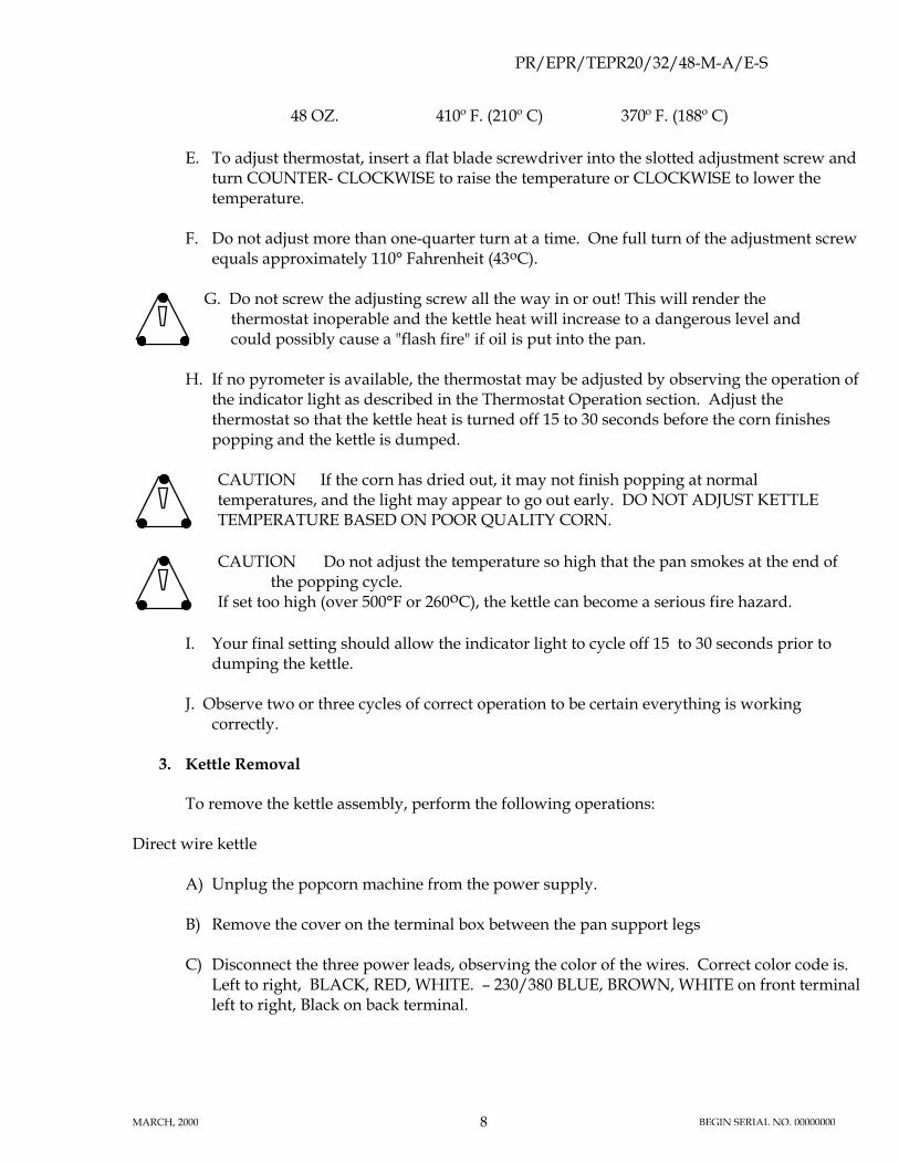
48 OZ. 410º F. (210º C) 370º F. (188º C)
E. To adjust thermostat, insert a flat blade screwdriver into the slotted adjustment screw andturn COUNTER- CLOCKWISE to raise the temperature or CLOCKWISE to lower thetemperature.
F. Do not adjust more than one-quarter turn at a time. One full turn of the adjustment screwequals approximately 110° Fahrenheit (43oC).
G. Do not screw the adjusting screw all the way in or out! This will render thethermostat inoperable and the kettle heat will increase to a dangerous level andcould possibly cause a "flash fire" if oil is put into the pan.
H. If no pyrometer is available, the thermostat may be adjusted by observing the operation ofthe indicator light as described in the Thermostat Operation section. Adjust thethermostat so that the kettle heat is turned off 15 to 30 seconds before the corn finishespopping and the kettle is dumped.
CAUTION If the corn has dried out, it may not finish popping at normaltemperatures, and the light may appear to go out early. DO NOT ADJUST KETTLETEMPERATURE BASED ON POOR QUALITY CORN.
CAUTION Do not adjust the temperature so high that the pan smokes at the end ofthe popping cycle.
If set too high (over 500°F or 260oC), the kettle can become a serious fire hazard.
I. Your final setting should allow the indicator light to cycle off 15 to 30 seconds prior todumping the kettle.
J. Observe two or three cycles of correct operation to be certain everything is workingcorrectly.
3. Kettle Removal
To remove the kettle assembly, perform the following operations:
Direct wire kettle
A) Unplug the popcorn machine from the power supply.
B) Remove the cover on the terminal box between the pan support legs
C) Disconnect the three power leads, observing the color of the wires. Correct color code is.Left to right, BLACK, RED, WHITE. – 230/380 BLUE, BROWN, WHITE on front terminalleft to right, Black on back terminal.

PR/EPR/TEPR20/32/48-M-A/E-S
MARCH, 2000 9 BEGIN SERIAL NO. 00000000
D) Remove the two bolts on the side of the aluminum pan legs.
E) Using proper lifting techniques, remove the kettle by lifting it straight up.
F) Turn the kettle upside down and remove the bolts that hold the dump handle andretainer and lift the retainer off the kettle.
G) When removing nuts and spacers from the threaded studs on the bottom of the pan, donot wipe off the silver lubricant. Without this lubricant (NEVER SEEZ) the nuts mayfreeze on the studs and cause the studs to break when the nuts are turned in an attempt toremove them.
H) When reassembling the kettle, be sure that all electrical connections are secure. A looseconnection can heat up and burn off the wires. Tighten the bolts that hold the retainerexcept for the four bolts around the pan leg plate.
I) Set the kettle back in place and replace the two bolts in the pan legs.
J) Locate the kettle so that the clutch dog lines up with the motor drive head, and tighten thetwo front bolts that hold the pan leg plate, then tip the kettle and tighten the other twobolts.
K) Turn on the agitator motor and dump the kettle. If the drive head does not engage anddisengage freely, readjust the kettle.
4. Kettle Spring Adjustment
The purpose of the kettle counter balance springs is to reduce the force required to dumpthe kettle. The spring collars are held in place by set screws that fit into holes drilled on thebottom of the cross shaft. The spring collars have five holes that the spring fits into. Byturning the collar around, all five of the holes may be used for spring tension adjustment.
When correctly adjusted the springs will neutralize the weight of the kettle. To set thesprings raise the kettle to a point where it is balanced. The long leg of the 1902 springshould be just beginning to touch the bar on the bottom edge of the hinge casting and the1903 spring will begin to move away from the bar. If the springs press against the bar toosoon the kettle will seem lighter but the springs are fighting each other. This condition willshorten the life of the springs.
An important part of this assembly are the two washers between the 1902 spring and theplate welded to the cross shaft. They act as both bearings and spacers; without them thespring may have a short life.

PR/EPR/TEPR20/32/48-M-A/E-S
MARCH, 2000 10 BEGIN SERIAL NO. 00000000

PR/EPR/TEPR20/32/48-M-A/E-S
MARCH, 2000 11 BEGIN SERIAL NO. 00000000
IX TROUBLE SHOOTING
1. Problem - Popping is slow---(Slow popping on first two cycles is normal)
QUESTION: Were the correct amounts of corn and oil used?
Refer to the chart in the operating section for the correct quantities.
QUESTION: Does the kettle indicator light go out more than 30 seconds before the cornfinishes popping?
YES! Temperature set too low - See section on how to adjust temperature.
CAUTION If the corn has dried out, it may not finish popping at normaltemperatures, and the light may appear to go out early. DO NOT ADJUST KETTLETEMPERATURE BASED ON POOR QUALITY CORN.
CAUTION Do not adjust the temperature so high that the pan smokes at the end ofthe popping cycle.
If set too high (over 500°F or 260oC), the kettle can become a serious fire hazard.
NO!
A. Voltage may be low - check voltage at circuit breaker with kettle heat ‘ON’.Extension cords or inadequate wiring will provide full voltage, if no load is applied.Once the kettle heat and auxiliaries are turned on, the voltage may drop 5 to 10volts.
B. If indicator light stays ‘ON’, for the full popping cycle one element in a multi-element pan may be have failed. Use an ammeter to diagnose.
Place the ammeter around the black or red lead to the popper kettle. The following currentdraws are normal:
KETTLE SIZE AMPS @ 200V. AMPS @ 208V. AMPS @230V. AMPS @ 240V.
20 oz. 12.5 13.0 10.8 11.232 oz. 19.6 20.4 17.0 17.748 oz. 26.8 28.1 23.4 24.4
380V – Place the ammeter around the black or brown lead to the popper kettle
PR/EPR/TEPR20/32/48-M-A/E-S
MARCH, 2000 12 BEGIN SERIAL NO. 00000000
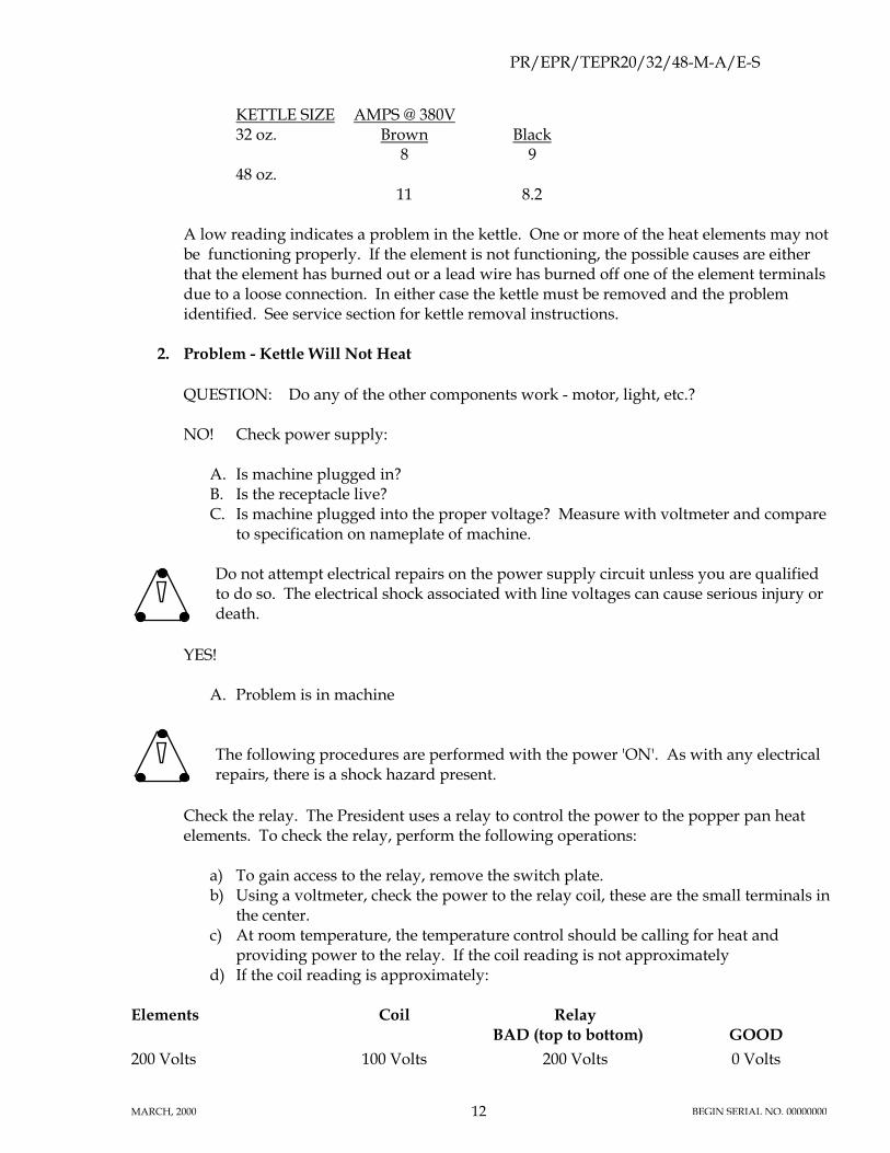
KETTLE SIZE32 oz.
48 oz.
AMPS @ 380VBrown
8
11
Black9
8.2
A low reading indicates a problem in the kettle. One or more of the heat elements may notbe functioning properly. If the element is not functioning, the possible causes are eitherthat the element has burned out or a lead wire has burned off one of the element terminalsdue to a loose connection. In either case the kettle must be removed and the problemidentified. See service section for kettle removal instructions.
2. Problem - Kettle Will Not Heat
QUESTION: Do any of the other components work - motor, light, etc.?
NO! Check power supply:
A. Is machine plugged in?B. Is the receptacle live?C. Is machine plugged into the proper voltage? Measure with voltmeter and compare
to specification on nameplate of machine.
Do not attempt electrical repairs on the power supply circuit unless you are qualifiedto do so. The electrical shock associated with line voltages can cause serious injury ordeath.
YES!
A. Problem is in machine
The following procedures are performed with the power 'ON'. As with any electricalrepairs, there is a shock hazard present.
Check the relay. The President uses a relay to control the power to the popper pan heatelements. To check the relay, perform the following operations:
a) To gain access to the relay, remove the switch plate.b) Using a voltmeter, check the power to the relay coil, these are the small terminals in
the center.c) At room temperature, the temperature control should be calling for heat and
providing power to the relay. If the coil reading is not approximatelyd) If the coil reading is approximately:
Elements Coil RelayBAD (top to bottom) GOOD
200 Volts 100 Volts 200 Volts 0 Volts

PR/EPR/TEPR20/32/48-M-A/E-S
MARCH, 2000 13 BEGIN SERIAL NO. 00000000
208 Volts 120 Volts 208 Volts 0 Volts230 Volts 230 Volts 230 Volts 0 Volts240 Volts 120 Volts 240 Volts 0 Volts400 Volts 230 Volts 230 Volts (same pole) 0 Volts (same pole)

PR/EPR/TEPR20/32/48-M-A/E-S
MARCH, 2000 14 BEGIN SERIAL NO. 00000000
B. Problem in kettle.
a) Remove kettle (see Service Section for removal instructions)b) Check for short circuits inside the kettle.c) If wires must be replaced, be sure to use nickel wire supplied Cretors. Conventional
copper or nickel plated "stove" wire will have limited life.d) Make a visual check for broken, loose, burned or heat damaged wires. If there are
no obvious broken or loose wires shorting out on the kettle, the elements must bechecked.
e) Perform a continuity test on the elements. It is possible that one of the elements hasburned through its insulation and casing and is shorting out directly to the kettlebottom.
Continuity test
Remove the nickel buss bars that connect the electrical terminals on the heat elements.Check each element between the following points:
Terminal to terminal 1.
2.
Continuity-functioning properly
No continuity-burned element; replace.First terminal to element case 1.
2.
Continuity to case from terminal indicates agrounded element; replace.
No continuity - functioning properlySecond terminal to elementcase
1.
2.
Continuity to case from terminal indicates agrounded element; replace.
No continuity - functioning properly
20 oz. - 208V elements 1983-D1447-D
9000 Watt – 48.1 Ω1800 Watt – 24.0 Ω2700 Watt - 16.0 Ω (total)
20 oz. – 240V elements 1983-C1447-C
900 Watt – 64.0 Ω1800 Watt – 32.0 Ω2700 Watt - 21.3 Ω (total)
32 oz. – 208V elements 1448-D1528-D1043-D
750 Watt – 57.7 Ω1500 Watt – 28.8 Ω2000 Watt – 21.6 Ω4250 Watt - 10.7 Ω (total)
32 oz. – 240V elements 1448-C1528-C1043-C
750 Watt – 76.8 Ω1500 Watt – 33.4 Ω2000 Watt – 28.8 Ω4250 Watt - 13.6 Ω (total)

PR/EPR/TEPR20/32/48-M-A/E-S
MARCH, 2000 15 BEGIN SERIAL NO. 00000000
48 oz. – 208V elements 1010-D1808-D1447-D1043-D
750 Watt – 57.7 Ω1250 Watt – 34.7 Ω1800 Watt – 24.0 Ω2000 Watt – 21.6 Ω5800 Watt - 7.5 Ω (total)
48 oz. – 240V elements 1010-C1080-C1447-C1043-C
750 Watt – 76.8 Ω1250 Watt – 46.1Ω1800 Watt – 32.0Ω2000 Watt – 28.8Ω5800 Watt - 9.9 Ω (total)
Replace failed heat elements with identical units available from your local dealer or fromCretors. Reassemble and reinstall kettle assembly onto the machine.
3. Problem - Corn Burns
QUESTION: Is the agitator working?
YES!
A. Check to be certain the stirrer blade is on the bottom of the pan and is stirring thecorn.
B. Were the correct amounts of corn and oil used? See operation section for correctamounts.
C. Temperature set too high? - adjust temperature.
NO!
A. Check motor connections - loose wire.B. Motor bad - replace.
4. Problem in Cornditioner
The President series of machines has two cabinet sizes, 60" and 72".
The cornditioner heat system, in the 60" and 72" cabinets, is the same and consist of ablower, heating element, and a thermostat mounted in a removable box. The cornditionercirculates hot air through the popper case to keep popped corn hot and crisp. An indicatorlight next to the cornditioner switch indicates when there is power to the circuit.
With the power connected, turn the cornditioner 'ON'.
QUESTION: Is the indicator light ‘ON’ and no air being delivered?
A. Cornditioner screen blocked - clear passageway.B. Check connections to blower.

PR/EPR/TEPR20/32/48-M-A/E-S
MARCH, 2000 16 BEGIN SERIAL NO. 00000000
C. Replace blower.

PR/EPR/TEPR20/32/48-M-A/E-S
MARCH, 2000 17 BEGIN SERIAL NO. 00000000
QUESTION: Is the indicator light ‘ON’ and cool air is being supplied?
A. Check thermostat; replace.The maximum air output temperature is approximately 140° F. (60oC) Thethermostat is installed as a safety device and is not adjustable.
B. Check heat element; replace.
QUESTION: Is the indicator light ‘ON’ and air from blower too hot ?
A. Thermostat stuck in ‘ON’ position - replace.B. Blower not operating properly - replace.
5. Problem - Exhaust Odors
A. Wash grease filter.B. Replace charcoal media in the charcoal filter box.
6. Pump
Refer to pump service manual.

PR/EPR/TEPR20/32/48-M-A/E-S
MARCH, 2000 18 BEGIN SERIAL NO. 00000000
X OPERATING INSTRUCTIONS
1. Do not attempt to operate your Cretors popcorn machine until you have read andunderstood this manual. Failure to do so may result in serious injury or death.
2. Do not attempt to operate your Cretors popcorn machine unless the installationinstructions have been strictly adhered to. Failure to do so may result in seriousinjury or death.
3. Operate your popcorn machine only if it is in sanitary condition (SANITATIONINSTRUCTIONS). Failure to do so may result in illness to your customers.
4. Always turn ‘OFF’ the KETTLE HEAT switch when not popping corn. Failure todo so will cause oil to stain the kettle, possibly resulting in an unsanitarycondition. It may also cause a "flash" fire if oil is added to a kettle left unattendedwith the heat on, resulting in serious burns or death.
5. To operate your Cretors popcorn popping machine:
A. Fill the corn drawer with corn (all models) .
B. Fill the salt box and hang it on the inside edge of the corn drawer.
C. Connect and adjust the pump as explained in the installation instructions and preheat thepopping oil until liquid, if necessary.
D. Fill the corn measure with corn and the salt measure with salt, and empty these into thekettle. When making sugar corn, add the correct amount of sugar, rather than salt, withthe measure of corn.
E. Rotate the kettle lid closed using the counter weight as a handle. Avoid contactwith the kettle. Contact with a hot popping kettle may result in serious burns orscalds
CAUTION! Always add corn to the kettle before pressing the oil delivery button oradding oil. Failure to do so may result in the oil being heated too rapidly resulting in afire.
F. Turn 'ON' the agitator, turn 'ON' the exhaust fan, turn 'ON' the kettle heat.
G. Press the delivery button to pump the correct amount of oil into the kettle.

PR/EPR/TEPR20/32/48-M-A/E-S
MARCH, 2000 19 BEGIN SERIAL NO. 00000000
NOTE: After the first popping the kettle is hot. Avoid contact with the kettle whenadding corn or salt. Failure to do so may result in serious burns or scalds.
Measuring instruments have been provided to accurately measure the proper amounts ofpopcorn, salt and oil. The correct amount for each popping is:
SALTED CORN
VOLUMETRIC MEASUREKettle Size Corn Oil Salt
20 oz. 20 oz. 6.5 oz. 2 tsp.591 ml 192 ml
32 oz. 32 oz. 12.25 oz. 3 tsp.1083 ml 360 ml
48 oz. 48 oz. 16.5 oz. 4 tsp.1475 ml 492 ml
SUGAR CORN
VOLUMETRIC MEASUREKettle Corn Oil Sugar
20 oz. 12 oz. 4.25 oz. 8.25 oz.351 ml 122 ml 245 ml
32 oz. 19.5 oz. 7.5 oz. 15.25 oz.577 ml 225 ml 451 ml
48 oz. 28.7 oz. 10.5 oz. 2.75 oz.580 ml 307 ml 614 ml
H. As the corn pops, it will push the lid open. When the lid has moved about one and one-half inches, it will open completely, allowing the corn to discharge from the kettle. Whenthe corn finishes popping, dump the kettle by lifting the large black handle. Then whenthe pan is empty, return the kettle to the horizontal position.
Avoid contact with the kettle when dumping popped corn. Failure to do so may resultin serious burns or scalds.
I. When the oil container is empty, replace with new full container of oil.
PR/EPR/TEPR20/32/48-M-A/E-S
MARCH, 2000 20 BEGIN SERIAL NO. 00000000
J. Repeat steps D - G as desired, adding corn to the corn drawer and salt to the salt box asnecessary.
NOTE: The ideal time for maximum volume is between 2-3/4 to 3-1/2 minutes from thetime the corn is placed into the kettle until the time it is dumped. Check the popping timeafter several popping cycles. Reduce the charge of raw corn if the time is more than 3-1/2minutes and increase the charge if the time is less than 2-1/2 minutes per popping.
K. Follow the recommended sanitation procedures.
XI SANITATION INSTRUCTIONS
Be certain the machine is turned off and power is unplugged before sanitizing thismachine unless a specific cleaning procedure requires power to the machine. Failureto do so could result in injury or death.
Do not clean heated surfaces until they have been given sufficient time to cool. Failureto do so may result in serious burns or scalds.
1. Popping Kettle
A. Do not immerse an assembled pan in water. This will damage the electricalcomponents and my cause short circuits resulting in electrical shock hazard ifpower is applied.
B. Do not use steel wool or other similar abrasives to clean the kettle as they will ruin thekettle by removing the nickel plating.
C. Do not attempt to clean the kettle with power connected unless you are boiling the"CKC" cleaning compound to clean the inside of the kettle in step G.
D. Do not attempt to clean a hot kettle. Failure to do so may result in serious burns orscalds.
E. The kettle has a polished nickel finish and is very easy to clean if oil is not allowed to burnon it. After the final popping, the best practice is to wait until the oil just begins tosolidify, then take a cotton towel or absorbent rag and wipe the kettle. Once the oil isallowed to completely solidify, it can become more difficult to remove. We recommendcoconut oil for your Cretors popper; it will not stick or burn as easily as other oils.
F. The outside of the kettle should be cleaned with Cretors Outside Kettle Cleaner "COC"periodically to remove popping oil that may become baked on.

PR/EPR/TEPR20/32/48-M-A/E-S
MARCH, 2000 21 BEGIN SERIAL NO. 00000000
G. Clean the interior of the kettle every week with "CKC" cleaning compound. This willprevent the accumulation of carbon on the bottom and internal sides of the kettle. Whenusing "CKC" cleaning compound in the kettle, do not fill the kettle with more than 3/4"high of water inside the kettle. Heat the water to boiling and turn off the kettle heat, don'tboil the kettle dry. If the kettle has been overheated or oils that tend to carbonize are usedthe normal cleaning procedures may not suffice. Increase frequency as needed.
H. To properly clean the kettle it is necessary to remove cover and agitator assembly.
2. Kettle cover and agitator removal
A. To remove the kettle cover, remove the wing nuts, washers and anchor lugs holding thecover onto the kettle shield. Next, remove the kettle shield brackets, screws and wingnuts holding the kettle shield and apron onto the kettle.
B. The agitator assembly is disassembled by removing the anti-pak pin going through thetop of the stirrer blade. Lift off the stirrer blade. Place kettle in dump position and slidethe clutch dog and shaft out from the bottom of the pan. (If shaft will not easily drop out,use a hammer and lightly tap on the shaft to break it free. If it is apparent that the clutchdog and shaft cannot be removed, leave it in place, however at sometime in the future itwill be necessary to remove and replace the entire pan center and clutch dog assembly.This must be done before the clutch dog shaft becomes hard to turn; when the shaftbecomes hard to turn the agitator motor will be overloaded and damaged.)
C. Clean all parts thoroughly, making sure to use Cretors Kettle Cleaner. Do not use anyharsh abrasives or cleaning material. Pay particular attention to the interior of the bladecenter. Some popping oils will carbonize and build up on the interior of the blade centerand create a tight fit on the pan center. (normal clearance is 1/8" -- 3 mm ). When thishappens oil will 'wick-up' the narrow gap and leak down the clutch dog shaft and givethe appearance that the kettle is leaking oil. In extreme cases the carbon will cause theblade center to grip the pan center and turn it . This will loosen the pan center and aserious oil leak will occur. When reassembling lightly coat the clutch dog shaft with molygrease or a comparable high temperature lubricant.
D. Reassemble cover in reverse order, following the directions above.
3. Cabinet
A. Remove and empty the waste clean-out drawer daily or whenever it is full. Underheavy use this may need to be done more often. Failure to empty the drawer andclean cabinet may result in a fire hazard due to restricted air flow .
B. The cabinet glass and cabinet base can be cleaned with any good grade glass or householdcleaner suitable for glass and plastic surfaces. The inside of the cabinet can be cleanedwith the same cleaner as the outside, if it is the type that has a cleaning agent to cut the oilremaining from the popping operation, and it is acceptable for food contact surfaces.

PR/EPR/TEPR20/32/48-M-A/E-S
MARCH, 2000 22 BEGIN SERIAL NO. 00000000
C. The perforated screen of the 60" and 72" cabinets should be removed at least weekly ormore often if needed, to thoroughly clean the air chamber beneath of salt and small bits ofcorn which come through the air holes. The corn and scraps may be swept into the hot airwell in the center of the bin.
D. Remove the clean-out drawer from under the popper case bottom and slide it under thehot air well; then pull out the clean out slide. All the scrap will fall into the scrap drawer.When through, replace the clean out slide and the clean-out drawer.
4. Pump
Refer to manual supplied with pump.

PR/EPR/TEPR20/32/48-M-A/E-S
MARCH, 2000 23 BEGIN SERIAL NO. 00000000
SAFETY FIRST
The information in this manual is essential for the safe installation and maintenance ofyour Cretors popcorn machine. The manual must be read and understood beforeinstalling, operating or maintaining this equipment, or equivalent training must beprovided.
"The employer shall instruct each employee in the recognition and avoidance of unsafeconditions and the regulations applicable to his work environment to control oreliminate any hazards or other exposure to illness or injury". Ref.: 29 CFR 1926.20(b)(4)(a)(2)
It is understood that safety rules within individual companies vary. If a conflict existsbetween the safety procedures contained in this manual and the rules of a usingcompany, the more stringent rule should take precedence.
This manual is filled with time-saving and money-saving information regarding your Cretorspopcorn popper. There is nothing, however, more important than the safety aids and warningsfound throughout this document.
If you have any questions, contact your local dealer and if there are any additional questions, feelfree to contact the Customer Service Department at C. Cretors and Company.
Additional copies of this manual can be obtained from C. Cretors and Company at the addresslisted below. Please provide model and serial number when requesting additional copies of thismanual. There will be a nominal charge for additional copies.
Cretors guarantees this machine to be free of defects in parts, materials and workmanship for oneyear. Please take this time to fill out the factory registration card and return it to the factory toactivate your warranty. If you have any questions concerning the Cretors' warranty, please contactyour local dealer or the Customer Service department at C. Cretors and Company.
C. CRETORS AND COMPANY3243 N. CALIFORNIA AVENUECHICAGO, IL 60618PHONE (773) 588-1690, (800) 228-1885, FAX (773) 588-2171WEB SITE: http://www.cretors.com Email: [email protected]