Embed Size (px)
Citation preview

Mälardalen University Doctoral ThesisNo.171
Preservation ofExtra-Functional Properties in
Embedded SystemsDevelopment
Mehrdad Saadatmand
February 2015
School of Innovation, Design and EngineeringMälardalen University
Västerås, Sweden

Copyright c©Mehrdad Saadatmand, 2015ISSN 1651-4238ISBN 978-91-7485-151-9Printed by Arkitektkopia, Västerås, SwedenDistribution: Mälardalen University Press
AbstractThe interaction of embedded systems with their environments and theirresource limitations make it important to take into account propertiessuch as timing, security, and resource consumption in designing such sys-tems. These so-called Extra-Functional Properties (EFPs) capture anddescribe the quality and characteristics of a system, and they need to betaken into account from early phases of development and throughout thesystem’s lifecycle. An important challenge in this context is to ensurethat the EFPs that are defined at early design phases are actually pre-served throughout detailed design phases as well as during the executionof the system on its platform.
In this thesis, we provide solutions to help with the preservation ofEFPs, targeting both system design phases and system execution onthe platform. Starting from requirements, which form the constraintsof EFPs, we propose an approach for modeling Non-Functional Require-ments (NFRs) and evaluating different design alternatives with respectto the satisfaction of the NFRs. Considering the relationship and trade-off among EFPs, an approach for balancing timing versus security prop-erties is introduced. Our approach enables balancing in two ways: in astatic way resulting in a fixed set of components in the design model thatare analyzed and thus verified to be balanced with respect to the timingand security properties, and also in a dynamic way during the executionof the system through runtime adaptation. Considering the role of theplatform in preservation of EFPs and mitigating possible violations ofthem, an approach is suggested to enrich the platform with necessarymechanisms to enable monitoring and enforcement of timing properties.In the thesis, we also identify and demonstrate the issues related to ac-curacy in monitoring EFPs, how accuracy can affect the decisions thatare made based on the collected information, and propose a technique totackle this problem. As another contribution, we also show how runtime
i

ii
monitoring information collected about EFPs can be used to fine-tunedesign models until a desired set of EFPs are achieved. We have also de-veloped a testing framework which enables automatic generation of testcases in order verify the actual behavior of a system against its desiredbehavior.
On a high level, the contributions of the thesis are thus twofold:proposing methods and techniques to 1) improve maintenance of EFPswithin their correct range of values during system design, 2) identify andmitigate possible violations of EFPs at runtime.

Sammanfattning
Interaktionen mellan inbyggda system och dess miljöer gör det viktigtatt ta hänsyn till egenskaper såsom timing, säkerhet, och tillförlitlighetvid utformning av sådana system. Dessa så kallade Extra-FunktionellaEgenskaper (EFE:er) innefattar och beskriver kvalitet och egenskaperhos ett system, och måste beaktas tidigt i utvecklingsfasen samt underhela systemets livscykel. En central utmaning i detta sammanhang är attsäkerställa att de EFE:er som är definierade i tidiga designfaser bevarasgenom de detaljerade konstruktionsfaserna så väl som under exekverin-gen av systemet på sin plattform.
I denna avhandling tillhandahåller vi lösningar för att stödja bevaran-det av EFE:er, med inriktning på både systemkonstruktionsfaserna ochplattformsexekvering. Med utgångspunkt från kraven, som begränsarEFE:erna, föreslår vi en strategi för modellering av Icke-FunktionellaKrav (IFK) och utvärdering av olika designalternativ med avseende påuppfyllandet av IFK. Med kopplingen och avvägningen emellan EFE:eri åtanke, introduceras ett tillvägagångssätt för att balansera tidsegen-skaperna gentemot säkerhetsaspekterna. Vår metod gör det möjligt attbalansera på två sätt: statiskt, som resulterar i en fast uppsättning kom-ponenter i konstruktionsmodellen som analyseras och därigenom veri-fieras som balanserade med avseende på tids och säkerhetsegenskaper,samt dynamiskt genom anpassning under systemexekvering. Med hän-syn till plattformens roll i bevarandet av EFE:er samt mildrande aveventuella kränkningar, föreslås ett sätt för att berika en plattform mednödvändiga mekanismer för att möjliggöra övervakning samt säkerstäl-lande av tidsegenskaper. I avhandlingen både identifierar och demon-strerar vi problematiken med noggrannhet i övervakning av EFE:er, ochhur noggrannheten kan påverka de beslut som fattas grundat på in-samlad information, samt föreslår en teknik för att lösa detta problem.
iii
iv
Som ytterligare bidrag visar vi också på hur information om EFE:ersom insamlats genom övervakning under drift kan användas för att fin-justera designmodeller tills en önskad uppsättning EFE:er uppnås. Vihar också utvecklat ett ramverk för testning som möjliggör automatiskgenerering av testfall för kontrollera att faktiskt beteende hos ett systemöverensstämmer med önskat beteende.Som helhet är således avhandlingens bidrag dubbelt: föreslagna metoderoch tekniker till att 1) förbättra bevarandet av EFE:er inom tillåtet inter-vall under systemdesign, 2) identifiera och mildra eventuella överträdelserav EFE:er under körning. Ur detta perspektiv bidrar våra lösningar tillatt producera inbyggda system med bättre kvalitetssäkring.

Dissertation Opponent:
• Assoc. Prof. Vittorio Cortellessa - University of L’Aquila, Italy.
Grading Committee:
• Prof. Antonia Bertolino - National Research Council (CNR), Italy.
• Prof. Jan Bosch - Chalmers University of Technology, Sweden.
• Adj. Prof. Tiberiu Seceleanu - ABB Corporate Research, Sweden.
Grading Committee Reserve:
• Prof. Kristina Lundqvist - Mälardalen University, Sweden.
PhD Advisors:
• Prof. Mikael Sjödin - Mälardalen University, Sweden.
• Dr. Antonio Cicchetti - Mälardalen University, Sweden.
v


To my dear family,Massoud, Forough, Mahnaz, Farshid & Farshad.

“A PhD is someone who knows everything about something & somethingabout everything” - anonymous.

AcknowledgementsThe journey towards a PhD degree is full of joy, ups and downs, excite-ments, and challenges. There have been many people who have beenwith me throughout this journey; people from which I have learned alot, shared our joys and excitements together, those that together weworked countless hours to solve problems and tackle challenges, thosewho provided support and made the progress smoother and easier, andthose people whose mere acquaintance and presence have been a greatsource of inspiration and motivation.
Hereby, I would like to thank my supervisors Mikael Sjödin and An-tonio Cicchetti for their support, encouragement, and all the things thatI learned from them helping me become a better researcher. Thanks toRadu Dobrin, Jan Carlson and Cristina Seceleanu for their invaluablecomments and tips. I had the pleasure of sharing the office with Federicoand Antonio with whom I have also great and unforgettable memoriesfrom all the travels that we did together. I would also like to thank mymanagers and colleagues at Alten and Enea, particularly Detlef Scholle.
The success of Mälardalen Real-Time Research Centre (MRTC) atIDT with its friendly, pleasant and enriching environment is due to thehard work and presence of many great people and researchers and I amglad that I have had the chance to be part of such an environment.My studies at MDH also gave me the opportunity to meet new friendsand work with many wonderful people. I would like to thank themall here for the all the great moments. Thanks also to the ITS-EASYgraduate school staff for their support, and the nice educational eventsthey organized.
My deepest gratitude to my family who have always been there forme. Without them I could have never reached this far.
Mehrdad SaadatmandVästerås, February 2015
ix


List of Publications
Papers Included in the PhD Thesis1
Paper A Model-Based Trade-off Analysis of Non-Functional Require-ments: An Automated UML-Based Approach. Mehrdad Saadat-mand, Antonio Cicchetti, Mikael Sjödin. Journal of AdvancedComputer Science, Vol. 3, No. 11, November, 2013.
Paper B Managing Timing Implications of Security Aspects in Model-Driven Development of Real-Time Embedded Systems. MehrdadSaadatmand, Thomas Leveque, Antonio Cicchetti, Mikael Sjödin.International Journal On Advances in Security, Vol. 5, No. 3&4,December, 2012.
Paper C Monitoring Capabilities of Schedulers in Model-Driven De-velopment of Real-Time Systems. Mehrdad Saadatmand, MikaelSjödin, Naveed Ul Mustafa. 17th IEEE International Conferenceon Emerging Technologies & Factory Automation (ETFA), Krakow,Poland, September, 2012.
Paper D An Automated Round-trip Support Towards Deployment As-sessment in Component-based Embedded Systems. Federico Cic-cozzi, Mehrdad Saadatmand, Antonio Cicchetti, Mikael Sjödin.16th International Symposium on Component-Based Software En-gineering (CBSE), Vancouver, Canada, June, 2013.
1The included articles have been reformatted to comply with the PhD thesislayout.
xi
xii
Paper E Towards Accurate Monitoring of Extra-Functional Propertiesin Real-Time Embedded Systems. Mehrdad Saadatmand, MikaelSjödin. 19th Asia-Pacific Software Engineering Conference (APSE-C), Hong Kong, December, 2012.
Paper F A Model-Based Testing Framework for Automotive EmbeddedSystems. Raluca Marinescu, Mehrdad Saadatmand, Alessio Bu-caioni, Cristina Seceleanu, Paul Petterson. 40th Euromicro Confer-ence on Software Engineering and Advanced Applications (SEAA),Verona, Italy, August, 2014.
Paper G Testing of Timing Properties in Real-Time Systems: Verify-ing Clock Constraints. Mehrdad Saadatmand, Mikael Sjödin. 20thAsia-Pacific Software Engineering Conference (APSEC), Bangkok,Thailand, December, 2013.

xiii
Related Publications not Included in the PhDThesisLicentiate Thesis2
1. Satisfying Non-Functional Requirements in Model-Driven Devel-opment of Real-Time Embedded Systems. Mehrdad Saadatmand,Licentiate Thesis, ISSN 1651-9256, ISBN 978-91-7485-066-6, May,2012.
Conferences & Workshops1. A Fuzzy Decision Support Approach for Model-Based Tradeoff Anal-
ysis of Non-Functional Requirements. Mehrdad Saadatmand, Sa-har Tahvili. 12th International Conference on Information Tech-nology : New Generations (ITNG), Las Vegas, USA, April, 2015.
2. Mapping of State Machines to Code: Potentials and Challenges.Mehrdad Saadatmand, Antonio Cicchetti. The Ninth InternationalConference on Software Engineering Advances (ICSEA), Nice, Fra-nce, October, 2014.
3. OSLC Tool Integration and Systems Engineering - The Relation-ship Between The Two Worlds. Mehrdad Saadatmand, Alessio Bu-caioni. 40th Euromicro Conference on Software Engineering andAdvanced Applications (SEAA), Verona, Italy, August, 2014.
4. Runtime Verification of State Machines and Defect LocalizationApplying Model-Based Testing. Mehrdad Saadatmand, Detlef Scho-lle, Cheuk Wing Leung, Sebastian Ullström, Joanna FredrikssonLarsson. First Workshop on Software Architecture Erosion andArchitectural Consistency (SAEroCon) (ACM) (Co-located withWICSA 2014), Sydney, Australia, April, 2014.
5. Run-Time Monitoring of Timing Constraints: A Survey of Meth-ods and Tools. Nima Asadi, Mehrdad Saadatmand, Mikael Sjödin.The Eighth International Conference on Software Engineering Ad-vances (ICSEA), Venice, Italy, October 27 - November 1, 2013.
2A licentiate degree is a Swedish graduate degree halfway between M.Sc. andPh.D.

xiv
6. On Combining Model-Based Analysis and Testing. Mehrdad Saa-datmand, Mikael Sjödin. 10th International Conference on Infor-mation Technology : New Generations (ITNG), Las Vegas, USA,April, 2013.
7. Toward Model-Based Trade-off Analysis of Non-Functional Require-ments. Mehrdad Saadatmand, Antonio Cicchetti, Mikael Sjödin.38th Euromicro Conference on Software Engineering and AdvancedApplications (SEAA), Cesme-Izmir, Turkey, September, 2012.
8. Modeling Security Aspects in Distributed Real-Time Component-Based Embedded Systems. Mehrdad Saadatmand, Thomas Lev-eque. 9th International Conference on Information Technology :New Generations (ITNG), Las Vegas, USA, April, 2012.
9. Design of Adaptive Security Mechanisms for Real-Time EmbeddedSystems. Mehrdad Saadatmand, Antonio Cicchetti, Mikael Sjödin.4th International Symposium on Engineering Secure Software andSystems (ESSoS), Eindhoven, The Netherlands, February, 2012.
10. UML-Based Modeling of Non-Functional Requirements in Telecom-munication Systems. Mehrdad Saadatmand, Antonio Cicchetti,Mikael Sjödin. The Sixth International Conference on SoftwareEngineering Advances (ICSEA), Barcelona, Spain, October, 2011
11. On Generating Security Implementations from Models of Embed-ded Systems. Mehrdad Saadatmand, Antonio Cicchetti, MikaelSjödin. The Sixth International Conference on Software Engineer-ing Advances (ICSEA), Barcelona, Spain, October, 2011.
12. Enabling Trade-off Analysis of NFRs on Models of Embedded Sys-tems. Mehrdad Saadatmand, Antonio Cicchetti, Mikael Sjödin.16th IEEE International Conference on Emerging Technologies& Factory Automation (ETFA), WiP session, Toulouse, France,September, 2011.
13. A Methodology for Designing Energy-aware Secure Embedded Sys-tems. Mehrdad Saadatmand, Antonio Cicchetti, Mikael Sjödin.6th IEEE International Symposium on Industrial Embedded Sys-tems (SIES), Västerås, Sweden, June, 2011.

xv
14. Toward a Tailored Modeling of Non-Functional Requirements forTelecommunication Systems. Mehrdad Saadatmand, Antonio Cic-chetti, Diarmuid Corcoran, Mikael Sjödin. 8th International Con-ference on Information Technology : New Generations (ITNG),Las Vegas, USA, April, 2011.
15. On the Need for Extending MARTE with Security Concepts. Mehr-dad Saadatmand, Antonio Cicchetti, Mikael Sjödin. 2nd Interna-tional Workshop on Model Based Engineering for Embedded Sys-tems Design (M-BED), Grenoble, France, March, 2011.


Contents
I Thesis 1
1 Introduction 31.1 Background and Motivation . . . . . . . . . . . . . . . . . 41.2 Problems and Contributions Overview . . . . . . . . . . . 71.3 Thesis Outline . . . . . . . . . . . . . . . . . . . . . . . . 9
2 Research Context 112.1 Research Goals . . . . . . . . . . . . . . . . . . . . . . . . 122.2 Research Process . . . . . . . . . . . . . . . . . . . . . . . 13
3 Contributions 153.1 Overview of the Included Papers . . . . . . . . . . . . . . 24
4 Related Work 31
5 Conclusion and Future Directions 39
Bibliography 43
II Included Papers 51
6 Paper A:Model-Based Trade-off Analysis of Non-Functional Re-quirements: An Automated UML-Based Approach 536.1 Introduction . . . . . . . . . . . . . . . . . . . . . . . . . . 556.2 Non-Functional Requirements . . . . . . . . . . . . . . . . 586.3 Addressing the Challenges of NFRs . . . . . . . . . . . . . 62
xvii

xviii Contents
6.4 Suggested Approach . . . . . . . . . . . . . . . . . . . . . 646.5 Usage Example . . . . . . . . . . . . . . . . . . . . . . . . 706.6 Discussion . . . . . . . . . . . . . . . . . . . . . . . . . . . 746.7 Related Work . . . . . . . . . . . . . . . . . . . . . . . . . 766.8 Summary and Conclusion . . . . . . . . . . . . . . . . . . 806.9 Acknowledgements . . . . . . . . . . . . . . . . . . . . . . 81Bibliography . . . . . . . . . . . . . . . . . . . . . . . . . . . . 83
7 Paper B:Managing Timing Implications of Security Aspects inModel-Driven Development of Real-Time Embedded Sys-tems 897.1 Introduction . . . . . . . . . . . . . . . . . . . . . . . . . . 917.2 Security in Embedded Systems . . . . . . . . . . . . . . . 947.3 Motivation Example: Automatic Payment System . . . . 967.4 Approach . . . . . . . . . . . . . . . . . . . . . . . . . . . 997.5 Implementation . . . . . . . . . . . . . . . . . . . . . . . . 1017.6 Runtime Adaptation . . . . . . . . . . . . . . . . . . . . . 1127.7 Discussion . . . . . . . . . . . . . . . . . . . . . . . . . . . 1177.8 Related Work . . . . . . . . . . . . . . . . . . . . . . . . . 1187.9 Conclusion and Future Work . . . . . . . . . . . . . . . . 1217.10 Acknowledgements . . . . . . . . . . . . . . . . . . . . . . 122Bibliography . . . . . . . . . . . . . . . . . . . . . . . . . . . . 123
8 Paper C:Monitoring Capabilities of Schedulers in Model-DrivenDevelopment of Real-Time Systems 1298.1 Introduction . . . . . . . . . . . . . . . . . . . . . . . . . . 1318.2 Background and Motivation . . . . . . . . . . . . . . . . . 1338.3 Scheduler Design and Implementation . . . . . . . . . . . 1378.4 Experiment and Monitoring Results . . . . . . . . . . . . 1468.5 Related Work . . . . . . . . . . . . . . . . . . . . . . . . . 1538.6 Discussion and Conclusion . . . . . . . . . . . . . . . . . . 1548.7 Acknowledgements . . . . . . . . . . . . . . . . . . . . . . 156Bibliography . . . . . . . . . . . . . . . . . . . . . . . . . . . . 157

Contents xix
9 Paper D:An Automated Round-trip Support Towards DeploymentAssessment in Component-based Embedded Systems 1619.1 Introduction . . . . . . . . . . . . . . . . . . . . . . . . . . 1639.2 Context . . . . . . . . . . . . . . . . . . . . . . . . . . . . 1659.3 Related Work . . . . . . . . . . . . . . . . . . . . . . . . . 1689.4 The AAL2 Subsystem: a Running Example . . . . . . . . 1719.5 The Round-trip Support . . . . . . . . . . . . . . . . . . . 1739.6 From Models to Code and Back . . . . . . . . . . . . . . . 1769.7 Discussion and Future Work . . . . . . . . . . . . . . . . . 1839.8 Conclusion . . . . . . . . . . . . . . . . . . . . . . . . . . 1859.9 Acknowledgments . . . . . . . . . . . . . . . . . . . . . . . 186Bibliography . . . . . . . . . . . . . . . . . . . . . . . . . . . . 187
10 Paper E:Towards Accurate Monitoring of Extra-Functional Prop-erties in Real-Time Embedded Systems 19110.1 Introduction . . . . . . . . . . . . . . . . . . . . . . . . . . 19310.2 OSE Real-Time Operating System . . . . . . . . . . . . . 19410.3 Priority-Based Monitoring Approach . . . . . . . . . . . . 19510.4 Evaluation . . . . . . . . . . . . . . . . . . . . . . . . . . . 19710.5 Discussions . . . . . . . . . . . . . . . . . . . . . . . . . . 19910.6 Related Work . . . . . . . . . . . . . . . . . . . . . . . . . 20010.7 Conclusion and Future Work . . . . . . . . . . . . . . . . 20110.8 Acknowledgements . . . . . . . . . . . . . . . . . . . . . . 201Bibliography . . . . . . . . . . . . . . . . . . . . . . . . . . . . 203
11 Paper F:A Model-Based Testing Framework for Automotive Em-bedded Systems 20511.1 Introduction . . . . . . . . . . . . . . . . . . . . . . . . . . 20711.2 Preliminaries . . . . . . . . . . . . . . . . . . . . . . . . . 20811.3 Brake-by-Wire Case Study: Functionality and Structure . 21211.4 From EAST-ADL to Code Validation:
Methodology Overview . . . . . . . . . . . . . . . . . . . . 21411.5 Implementation Activities . . . . . . . . . . . . . . . . . . 21511.6 Testing Activities . . . . . . . . . . . . . . . . . . . . . . . 21811.7 Brake-by-Wire Revisited: Applying the Methodology . . . 22111.8 Related Work . . . . . . . . . . . . . . . . . . . . . . . . . 227

xx Contents
11.9 Conclusions and Future Work . . . . . . . . . . . . . . . . 22811.10Acknowledgment . . . . . . . . . . . . . . . . . . . . . . . 229Bibliography . . . . . . . . . . . . . . . . . . . . . . . . . . . . 231
12 Paper G:Testing of Timing Properties in Real-Time Systems: Ver-ifying Clock Constraints 23512.1 Introduction . . . . . . . . . . . . . . . . . . . . . . . . . . 23712.2 Background Context . . . . . . . . . . . . . . . . . . . . . 23812.3 Proposed Approach . . . . . . . . . . . . . . . . . . . . . . 24212.4 Application & Implementation of the Approach . . . . . . 24412.5 Related Work . . . . . . . . . . . . . . . . . . . . . . . . . 24612.6 Conclusion . . . . . . . . . . . . . . . . . . . . . . . . . . 24812.7 Acknowledgements . . . . . . . . . . . . . . . . . . . . . . 249Bibliography . . . . . . . . . . . . . . . . . . . . . . . . . . . . 251

I
Thesis
1


Chapter 1
Introduction
Once upon a time programmers used to get excited when they found outthat the programs they had punched on a card just worked and couldperform the expected calculations and functions. Although the com-puters back then also had their own limitations in terms of memory andprocessing capacity, getting the right functionality done was a big enoughchallenge in itself, which also meant not needing to redo programmingon another punchcard. With respect to complexity, computer systemstoday are rapidly becoming more and more complex. There are severalfactors that contribute to this complexity. One factor is the growing de-mands and expectations on the services provided by these systems. Forinstance, more tasks are delegated to software and electric/electroniccomponents in a car nowadays, which used to be performed solely bymechanical and hydraulic parts. On the other hand, the complexity ofeach service itself is increasing as well. Another aspect that contributesto the complexity issue is the complexity and variety of the infrastruc-ture and platforms on which systems are deployed; i.e., different operat-ing systems and frameworks (e.g., Android, iOS, .NET, JVM), differenthardware (e.g., single core, multicore, 32/64-bit processors). In caseof embedded systems, limitations and constraints on available resourcesalso add another dimension to the complexity issue. This means thatsuch systems should operate within certain constraints. In other words,other concerns than just logical correctness of operations can play animportant role in determining the success and correctness of embeddedsystems. These limitations and constraints are captured in the form of
3

4 Chapter 1. Introduction
Non-Functional Requirements (NFRs) and Extra-Functional Properties(EFPs). However, EFPs like NFRs [1] cannot be considered individuallyas they have interdependencies and mutual impacts and tuning one EFPcan affect another one.
The ultimate goal in the design of a software system is to deliver aproduct which satisfies all the requirements of different stakeholders. Toassess the fulfillment of this goal, not only it is needed to be able to verifycertain properties in the end product (e.g., timing properties), but also itis important from early design phases to consider a set of system compo-nents, among different alternatives, that have desired properties in linewith and contributing to the overall satisfaction of system requirementsand not violating them. One important challenge in this context is thatas we build a system and go down the abstraction levels and finally getto its execution, the properties of interest which are related and relevantto the satisfaction of system requirements should be preserved and notdeviate from their desired values. For example, if at runtime the execu-tion time of a task exceeds a certain threshold and value, it can impactthe satisfaction of a timing requirement on end-to-end response time inthe system.
Considering the aforementioned points, two challenges with respectto EFPs in embedded systems can be identified: 1-coming up with asystem design (e.g., models) which respects the desired set of properties(considering their interdependencies and trade-offs); and 2-making surethat those properties remain valid in the final product and during ex-ecution. The solutions that are provided in this thesis under the titleof preservation of extra-functional properties mainly tackle these two is-sues. The importance of the contributions of this thesis lies in the factthat regardless of the type and amount of analyses done in building asystem, if there are any deviations between the expected EFPs and theactual ones at runtime, the developed system might be then a failure.
1.1 Background and MotivationThe number of computer systems that we use in our daily life whichare embedded as part of other devices and systems is rapidly growing.Examples of such systems are microwave ovens, automobiles, TV sets,digital cameras, and refrigerators. Embedded computer systems are sys-tems that are designed basically to control and operate as part of other

1.1 Background and Motivation 5
devices. These systems are usually designed for specific and dedicatedoperations, and interact with their external environment through sen-sors and actuators [2, 3]. This interaction often brings along additionalrequirements such as real-time and safety. However, besides such re-quirements, resource constraints in these systems also introduce otherrequirements with respect to power consumption, processing capacity,memory usage, etc. Due to resource constraints that these systems have,their correctness depends not only on providing the right functionalitybut also respecting the constraints that they have. For this reason, itis of great importance to be able to evaluate EFPs and preserve themwithin their acceptable range of values mitigating possible violations ofthem at runtime.
In this context, requirements serve as a means for capturing andexpressing the needs of different stakeholders of the system. Consid-ering the variety of stakeholders, requirements can be originated fromdifferent sources; such as customers and end users, standards and reg-ulations, developers and refinement of higher level requirements, devel-opment tools, operational context and environment of the system, andso on. As for Non-Functional Requirements (NFRs), they have specificchallenges which can make their satisfaction in a system a complicatedtask [4, 5, 6]. For instance, NFRs cannot usually be considered in iso-lation as they are interconnected and have dependencies, and also canspan different aspects and parts of a system. Therefore, in satisfying anNFR, its impacts on other NFRs should also be taken into account, andtrade-off analysis among NFRs needs to be done [7, 8]. A similar pro-cedure needs to be done for EFPs when adjusting and tuning differentproperties of the system.
There is a clear and important (but sometimes misunderstood) rela-tionship between NFR and EFP. For example, ’response time of a com-ponent should not exceed 2ms’ is a requirement, while ’response timeof component A never exceeds 2ms’ or ’response time of component Bis equal to 1ms’ are expressions of properties. It is only in relation toa requirement that it becomes possible to then talk about validity/in-validity or ’goodness/badness’ of the value of a property. For instance,just knowing that a software component has the worst-case executiontime of 200ms does not help in determining if it is suitable to be usedin building a particular system or not. Only when the requirements aretaken into account, this value gets meaning in the sense that if it is goodfor that system and context or not; in which case, another component

6 Chapter 1. Introduction
with a different worst-case execution time might be adopted. Similarly,when monitoring and evaluating EFPs, requirements are needed in or-der to determine if the value of an EFP is valid and acceptable or not.Balancing trade-offs among requirements can also incur adjusting sys-tem properties that are related to those requirements. Therefore, thereis a relationship between an NFR and EFPs in a system and in orderto satisfy an NFR, its related extra-functional properties should havevalid values. For example, to satisfy performance requirements in a real-time system, execution and response time values of tasks (among others)should remain within a valid range.
To tackle the design complexity issue of embedded systems, Model-Driven Development (MDD) is a promising approach. It aids by rais-ing abstraction level and reducing design complexity, which also enablesanalysis at earlier phases of development. This helps with the identifi-cation of problems before the implementation phase [9, 10], noting thatthe cost of problems when found at later phases, especially in the codeand at runtime, grows exponentially [11, 12, 13]. The implementation ofthe system can also be generated from the design models through (a setof) model transformations. As more abstraction levels are introduced indesigning a system, it becomes also important to verify consistency ofdesign artifacts and their properties at each level. This means that foreach transformation, input properties should be preserved in the out-put of the transformation. This also includes the system execution atruntime which is the result of executing the generated source code, im-plying that the execution platform should be able to actively monitorand preserve extra-functional properties at runtime. To this end, theexecution platform also requires to be semantically aware of the speci-fied properties and related events in order to monitor them and detecttheir deviations. In the context of MDD, preservation of EFPs also gainsspecial importance and interest as it is ultimately the object code whichis executing and controlling a system, not models per se. Moreover, interms of timing properties, for instance, “models are only approximationof system implementations” and therefore, “inevitable time deviations ofthe implementation from the model appear” [14, 15].
Regardless of the applied development method and despite all typesof analyses done at earlier phases, the ultimate goal is to have a systemwhich behaves correctly and as intended at runtime and during its execu-tion. Moreover, for performing static analysis different assumptions aretaken into account. At runtime, situations may still occur that lead to

1.2 Problems and Contributions Overview 7
the violation of those assumptions which in turn can mean invalidationof analyses’ results [16, 17]. This again emphasizes the need for preser-vation of EFPs which constitute such assumptions, such as worst-caseexecution times of tasks, etc. For instance, it is very common nowa-days that modern CPUs have Dynamic Voltage and Frequency Scaling(DVFS) support for power management purposes. When DVFS is ap-plied, the CPU can go down to a lower frequency which then affects theexecution times of tasks. In such a scenario, the results of timing anal-ysis done assuming certain execution times of tasks based on a differentCPU frequency may not be valid anymore. Of course, in an ideal case,all such scenarios should be considered in the analysis. However, suchextensive and exhaustive analyses may not always be economical or evenpossible to perform, particularly in complex systems.
1.2 Problems and Contributions OverviewTo provide support for preservation of EFPs, we first start from NFRs,and considering the relationships between different NFRs we introducea method to evaluate their interdependencies and mutual impacts in ageneric manner. This step is necessary considering the relationship ofNFRs and EFPs as discussed in the previous section. Besides, early anal-ysis of NFRs is also important considering that different sets of NFRson the same set of functional requirements can result in different designdecisions and implementations. For instance, to sort some data under aspecific timing constraint, only certain sorting algorithms may be suit-able to use. However, if that timing constraint is relaxed but insteadthere is a constraint on maximum memory usage, a different set of sort-ing algorithms can then be considered as suitable. Moreover, due toresource limitations, the NFRs that are defined for an embedded sys-tem by different stakeholders need to be balanced and trade-off analysisamong them should be performed. As the next step in building a systemwhich respects its specified constraints, we introduce an approach for es-tablishing balance among different EFPs in an embedded system. Thisapproach is demonstrated by looking particularly into the relationshipbetween security and timing.
Another challenge is collecting information about each EFP in thesystem. In other words, appropriate mechanisms for monitoring EFPsare needed in order to determine whether a violation with respect to the

8 Chapter 1. Introduction
constraints of an EFP has occurred or not. Such monitoring informa-tion can then be used for different purposes: for example, to performruntime adaptation, enforcing the system constraints, testing EFPs, orsimply providing feedback on EFPs values collected during the systemexecution. Along with this goal, we have developed a method for collect-ing necessary information about the timing behavior of real-time systemsto identify violations such as deadline misses and execution time over-runs of real-time tasks. In this thesis, we also discuss and demonstratea method how such monitoring capabilities and the EFPs informationcollected using them can help with adjusting system models towardsreaching deployment configurations which ultimately result in a desiredset of EFPs’ values at runtime.
Moreover, we demonstrate how monitored information can be usedto perform runtime adaptation and also test a system with respect toits timing properties. For the former, a runtime adaptation mechanismhas been developed to balance timing aspects of a system versus itssecurity level by adopting different encryption algorithms with differenttiming properties. For the latter, we have developed a testing approachto verify whether the timing constraints (e.g., specified in the form ofclock constraints) in a system get violated at runtime or not.
As can be understood so far, one fundamental feature needed inachieving preservation of EFPs and to mitigate their possible violationsis the ability to monitor and collect information about EFPs. While suchcapability is assumed as provided in many previous works, it has its ownunique challenges. For instance, EFPs are of different nature and kind,and therefore, the way that necessary information is collected for eachone is a challenge in itself. Also accuracy of the collected informationplays an important role when deciding if an EFP is within an acceptablerange (as specified by an NFR). As another contribution of the thesis,we demonstrate the importance of this issue, how it can affect takingcorrect decisions about EFPs in a system, identify the factors that cancontribute to the accuracy of the collected information (or lack thereof),and provide a solution for mitigating it.
In summary, the main goal of the thesis is to highlight the chal-lenges with respect to the preservation of EFPs and provide techniquesand methods applicable at different levels of abstraction to increase ourconfidence that at the final step, namely runtime and during execution,EFPs do not deviate from their expected values and the system behavesas intended. While the proposed solutions have the potential to be ap-

1.3 Thesis Outline 9
plied for various EFPs, our main focus in this work is particularly ontiming properties.
1.3 Thesis OutlineThe thesis consists of two parts: Part I includes five chapters. Chapter1 provided an introduction to the thesis, described the background, andmain problems that this thesis addresses as well as an overall descriptionof the thesis contributions. Chapter 2 elaborates the research context,goals, and process. Contributions of the thesis are described in moredetail in Chapter 3. Chapter 4 discusses the related work and in Chapter5, the work is summarized and future directions are mentioned. Part IIof the thesis contains the published peer-reviewed papers that constituteand present the technical contributions of the thesis in detail, which areorganized in Chapters 6-12.


Chapter 2
Research Context
The main objective in this research work is to introduce methods forpreservation of extra-functional properties in embedded systems devel-opment and to mitigate their possible violations at runtime. This goalis based on the following principles and assumptions:
• For each EFP to be preserved, a set of values containing acceptableand valid values for that EFP can be considered. Values thatfall outside of this set are considered invalid, and thus violate theconstraints of the EFP (considering a specific context).
• Analysis can be performed on system models in order to evaluatesatisfaction feasibility of its non-functional requirements and toevaluate/calculate extra-functional properties of the system and itscomponents, such as response time. Analyses are based on someassumptions and preconditions. Violation of these assumptionscan lead to having invalid and erroneous analysis results.
• At runtime, several factors such as transient loads, difference be-tween the ideal execution environment (taken into account for anal-ysis) and the actual one, can lead to the violation of the assump-tions that were used to perform analysis [16].
• It may not be practical and/or economical to perform analysis onall types of extra-functional properties. In such cases, runtimemonitoring becomes even more important.
11
12 Chapter 2. Research Context
• As we go down the abstraction levels, an EFP may be refined andtranslated into one or more EFPs at the next levels. In that case,preservation of the former can incur preservation of the latter at adifferent abstraction level.
In this context, the term preserve that we use in our work impliesthat there is some knowledge about valid and invalid values (e.g., range ofvalues) that an extra-functional property can have in a specific contextand system; i.e., we actually preserve the validity of the value, ratherthan the actual value.
2.1 Research GoalsTo achieve the objective of the work, the following main research goalshave been defined:
• G1: Define an approach for establishing balance amongNFRs at the model level: The relationship between NFRs andEFPs makes it important to start from NFRs and evaluate andbalance them. For example, a requirement on end-to-end dead-lines and response times in a system might require use of certaincomponents with specific timing properties. If that requirement ischanged, another set of components with different timing proper-ties might be needed.
• G2: A model-based EFP-aware method resulting in prop-erty preserving system designs: Model-Based Developmentcan enable identification of problems earlier in the developmentphase. By exploiting this feature, system models can be analyzedand adjusted to have extra-functional properties within their de-sired and acceptable range of values, and thus, support EFP preser-vation from earlier phases of development.
• G3: A framework for monitoring and testing of extra-functional timing properties: Without monitoring EFPs atruntime we cannot be sure whether they are preserved or not(somehow analogous to the Schrödinger’s cat experiment [18]). Amonitoring mechanism is also needed if a system requires to ap-ply enforcement of EFPs (for instance, to preempt a task beforeit exceeds its worst-case execution time). Moreover, it should be

2.2 Research Process 13
possible to test a system with respect to its EFPs, which requiresto obtain and know the value of an EFP. In this research, we limitourselves to timing properties while an industrial tool should sup-port a wider range of EFPs.
2.2 Research ProcessThe main steps that have taken place in performing this research workare summarized and illustrated in Figure 2.1.
Investigation of the state of the art & practice
Research goals
Solutions
How to preserve EFPs?
Validation(application example, simulation,
industrial case study)
Figure 2.1: Research Steps
To achieve the overall objective of the thesis, namely preservation ofEFPs, several research goals have been defined. Moreover, the state ofthe art and practice have been consulted, which resulted in additionalresearch (sub-)goals or modification of already defined ones. To fulfillthe research goals, solutions have been proposed. These solutions were

14 Chapter 2. Research Context
validated in different ways: by an application example to demonstratehow, for instance, a method is applied; by simulation; or by performingan industrial case study. The arrow in the figure from Validation toResearch Goals indicates that in validating the solutions, new researchgoals or modification of existing ones have also formed and occurred.

Chapter 3
Contributions
In this section we provide the description of the main contributions ofthis work:
C1) Trade-off analysis and evaluation of conflicts among NFRs:To model interdependencies of NFRs and evaluate their impacts on eachother, we have proposed a UML profile. The profile offers necessaryconcepts to generically model an NFR along with its refinements whichcan include one or several other NFRs as well as functional parts thatcontribute to its satisfaction. This way, it enables to create a hierarchyof NFRs, form child-parent relationship among them, and also estab-lish relationships to the functional elements in the model that providerealization and implementations for NFRs. To enable trade-off analysisof NFRs in a quantitative manner, we introduce numerical properties aspart of the defined stereotypes in the profile. This allows to calculate thesatisfaction level of an NFR by taking into account both the contributiondegree of each of its children NFRs and any impacts that other NFRsin the system may have on it. To automate and perform the analysis,an in-place model transformation is used to traverse model elements,perform necessary calculations based on the algorithms that are imple-mented as part of the transformations, and then update the respectiveproperties of model elements with the calculated values. Based on theanalysis results, it can be determined if the planned decision designs tofulfill NFRs are acceptable or not.
In the profile, we also introduce the concept of deviation indicator
15

16 Chapter 3. Contributions
(in Paper A in the thesis) for requirements, which helps to identify partsof a system which have greater degree of deviation with respect to sat-isfaction of an NFR. This provides for several interesting features, suchas to prioritize test cases and focus testing activities on parts of the sys-tem with higher deviation indicator values (i.e., probably having more’severe’ problems) as demonstrated in a separate work of ours in [19].This is particularly interesting and beneficial considering that there isonly limited amount of resources (e.g., time or money) available for per-forming testing activities. Such prioritization based on the deviationindicator values allows for more efficient use of available resources fortesting.
Another variation of our approach based on the NFR profile is pre-sented in [20]; in which we have used fuzzy logic and decision supportsystems to identify best design alternatives (e.g., from a set of availablecomponents with different properties) in order to construct a system de-sign which is optimized with respect to the overall satisfaction level of itsNFRs. Application of fuzzy logic helps to relax the need for providingaccurate quantified values for relationships among NFRs, as is expectedin the original approach.
C2) Establishing balance between security and timing proper-ties: The choice of security mechanisms in real-time embedded systemswhere timing requirements are critical may not be trivial. For example,performing encryption using a strong encryption algorithm may takelonger time than using a weaker (but faster) encryption algorithm andthis may lead to the violation of timing requirements. Therefore, inimplementing security requirements, timing implications of the chosensecurity mechanisms should also be considered.
In this thesis, we provide two approaches to tackle this challenge. Inthe first one, we address it at the model level by identifying parts of thesystem (i.e., sensitive data) that need to be protected. For such parts,appropriate security features (in here, encryption and decryption com-ponents) to protect them are added to the original component model ofthe system. Then timing analysis is performed on the derived componentmodel to ensure that the security features which are added do not vio-late the timing requirements. In this approach, the original componentmodel of the system is used as input for a transformation that considersthe sensitive data flows in the input model and adds appropriate securitycomponents considering their timing properties. This approach leads to

17
a static design in the sense that a fixed and particular security mech-anism which is analyzed and thus, known to respect its allowed timebudget is always used in each execution. Our approach also providesa form of separation of concerns in the sense that instead of definingsecurity on the architectural (i.e., component) model, security engineers(or system designers) can now focus and annotate the data model, basedon which the component model is then updated (through model trans-formation) to include appropriate security mechanisms. Moreover, inthis way we also enable to bring security concerns into earlier phases ofdevelopment. Considering security at earlier phases of development isa need which is getting more and more attention in computer systemstoday, particularly in the embedded domain where security has its ownunique challenges (such as timing implications as we already discussed)[21].
However, the aforementioned solution may not be practical for sys-tems with high complexity which are hardly analyzable or systems withunknown timing properties of their components. For such systems, anadaptive approach to select appropriate security mechanisms based onthe state of the system can be used to adapt its behavior at runtimeand stay within the timing constraints. To this end, as a second andcomplementary way to establish balance between security and timing,we have suggested an approach for selecting appropriate encryption al-gorithms (in terms of their timing behaviors) at runtime in an adaptivefashion. The approach works by keeping a log for each execution ofthe encryption process. Based on the logged information, if a timingviolation is observed, a more suitable encryption algorithm (in terms oftiming properties) is adopted in the next execution. In other words, thesystem adapts itself at runtime to keep the timing constraints and reducethe number of timing violations. The idea behind this adaptation mech-anism is that when it is detected that an executing encryption algorithmis exceeding its allowed time budget, it can be more costly to terminateit in the middle of the encryption process and restart encrypting thedata with a less time-consuming encryption algorithm. Instead we letit finish its job and then use another encryption algorithm with a lowerexecution time in the next invocation of the encryption process.
In summary, the former approach aims to help with establishing bal-ance between security and timing properties at the design phase whensystem models are being created. In the second approach, this balanceis established in an adaptive way at a later phase, namely during system
18 Chapter 3. Contributions
execution and at runtime. These two approaches can of course be usedtogether in building a system in order to provide a higher degree of assur-ance to keep timing and security properties balanced and at acceptablelevels.
C3) Runtime monitoring and enforcement of EFPs: The ca-pabilities of platforms play an important role in preservation of extra-functional properties and mitigation of possible violations. To be ableto actively monitor and enforce EFPs, the platform needs to be seman-tically aware of them. With respect to timing properties, this awarenesscan include properties of a real-time task such as activation pattern (i.e.,periodic, sporadic, aperiodic), deadline, execution time, and so on. Theplatform needs to be aware of such properties so that, for example, itcan detect deadline misses or execution time overruns. This also im-plies that the platform needs to have respective monitoring mechanismsfor different timing properties. We have constructed a framework thatbrings such awareness about several timing properties to the platformand provides mechanisms for runtime monitoring and enforcement ofsuch properties.
Moreover, in the context of a model-based development method, itis important to verify that the actual values of EFPs at runtime are incompliance with those expected and defined at the model level. Theimportance of such capability becomes more clear remembering that theend goal of all different development methods and techniques is to have asystem which executes and behaves as expected at runtime with respectto both functional and extra-functional aspects. For this purpose, weshow how having a monitoring framework enables to also build and pro-vide a round-trip support in the development chain, constituting fromdesign models down to code and its execution on the platform and backagain to the models. In such a round-trip chain, monitoring informationis propagated back to the design models where the expected values arecompared with the actual values. If necessary, refinements and modifi-cations are done to the model(s) in order to finally have a system withthe desired set of EFPs. This is done by performing the process severaltimes until the refined models and the code that is generated from themresult in a system with satisfactory set of EFPs. This approach maywell be used towards optimizing design models for specific properties.We have applied and validated our proposed round-trip method on theEricsson’s ATM Adaptation Layer 2 (AAL2) subsystem.

19
C4) Testing of timing properties and runtime model verifica-tion: Another challenge with respect to timing properties is how to testthem. Testing EFPs, such as timing, can generally be a tricky task.One factor contributing to this issue is that testers need to collect andhave necessary information about timing properties of a system so thatthey can actually then test it. This brings us back to the previous pointabout the capability to monitor and observe timing properties. To im-prove testability of a system with respect to its timing properties, weintroduce a method and a testing framework that by exploiting moni-toring capabilities of the platform enables testing of timing properties.Of course, testing per se does not guarantee absence of errors, but bydetecting failures and fixing them it can help to increase our confidencein the correctness of a system. Our suggested testing approach enablesautomatic generation of Concrete Test Cases (CTC) (i.e., executable testscripts) from abstract ones (ATC: Abstract Test Cases) which are de-rived from Timed Automata (TA) models, executing them against thetarget, and determining timing issues and violations. This is done by im-plementing a parser which reads in ATCs and generates Python scriptsbased on them. This way, we not only enable testing of timing propertiesbut also do so in an automatic way. We have applied and validated ourapproach on the Brake-by-Wire (BBW) use-case provided by Volvo.
The result of testing also indicates if there is any deviation betweenthe intended behavior captured by models and the actual behavior ofthe system at runtime, which can also be useful in verifying architecturaldeviations and inconsistencies. This is important as models are also usedto perform model-based analysis. Therefore, if they do not correctlyrepresent a system’s behavior, the analyses that are done based on themmay also not be valid for that system.
Our proposed testing framework is covered by papers F and G in thethesis. In the former, the whole testing framework and test case genera-tion methodology are explained with a focus on functional requirements.In the latter, the extensions to also enable testing of timing require-ments are described (with a minor difference in how the System UnderTest (SUT) code is implemented for mapping states and transitions tocode [22], and a slightly different TA model for describing the internalbehavior of system components). In our testing approach, timed auo-mata are used to describe the internal behavior of the components of thetarget system which is modeled in EAST-ADL [23]. Figure 3.1 showsthe EAST-ADL model of the BBW system.

20 Chapter 3. Contributions
<<
desig
nF
un
ctionT
ype>
>
Fu
nctio
nalD
esig
nA
rchite
cture
<<
desig
nF
un
ctionP
roto
type>
>
pB
rakeP
edalS
enso
r<
<desig
nF
un
ctionP
roto
type>
>
pB
rakeT
orq
ueC
alcu
lator
<<
desig
nF
un
ctionP
roto
type>
>
pG
lob
alBrak
eC
on
troller
<<
desig
nF
un
ctionP
roto
type>
>
pW
heelS
enso
rFL
<<
desig
nF
un
ctionP
roto
type>
>
pA
BS
FL
<<
desig
nF
un
ctionP
roto
type>
>
pW
heelA
ctuato
rFL
structu
re
Po
sition
Po
sition_percen
tB
rakeP
edalP
os_
percen
tD
riverR
eqT
orq
ue
Whee
l_rp
m_F
LW
hee
lTorq
ue
Sp
eed_rp
m_F
LR
otatio
n_F
L
Requested
Torq
ue_F
L
Whee
lSpeed
_rp
m_F
L
Glo
balT
orq
ue
AB
ST
orq
ue_
FL
To
rqu
eCm
d_F
L
Brak
eT
orq
ue_
FL
Whee
l_rp
m_F
RV
ehic
leSp
eedE
st_km
ph
Vehic
leSp
eed_km
ph
_F
L
<<
desig
nF
un
ctionP
roto
type>
>
pW
heelS
enso
rFR
<<
desig
nF
un
ctionP
roto
type>
>
pA
BS
FR
<<
desig
nF
un
ctionP
roto
type>
>
+ W
hee
l Actu
ator
Sp
eed_rp
m_F
RR
otatio
n_F
R
Requested
Torq
ue_F
R
Whee
lSpeed
_rp
m_F
R AB
ST
orq
ue_
FR
To
rqu
eCm
d_F
RBrak
eT
orq
ue_
FR
Vehic
leSp
eed_km
ph
_F
R
Figure3.1:
The
EAST
-ADLmodelofthe
BBW
system.

21
The TA model of the Anti-lock Braking System (ABS) component inthe BBW system, without its timing and clock constraints, is depictedin Figure 3.2.
Entry
CalcSlipRate
Exitv>0 [ ]
v==0 [torqueABS=0]
v<5*(v-w*R) [torqueABS=0]
v>=5*(v-w*R) [torqueABS=wheelABS]
Figure 3.2: The TA description of the ABS function (without timing).
The TA models are analyzed and verified in Uppaal Port whichalso produces trace information constituting a path in the TA model.The trace information is parsed and transformed into executable testscripts which basically check behavioral conformance by verifying thatthe same set of states and transitions (or nodes and edges) are taken andvisited at runtime and in the same order. To take into account timingproperties, the time point at which each state is visited at runtime istimestamped. Doing so, it becomes possible to then check, for instance,how long it has taken to go from one state to another. Having suchinformation as part of the test result reports, comparisons can be doneagainst clock constraints and other timing annotations in the TA model,such as the model shown in Figure 3.3 (in which x represents a clock).
�����
������ ���
������������������
������������� ����������
�������������������� ����������
��������������������� ������������� ����
����
����
Figure 3.3: The TA description of the ABS function.

22 Chapter 3. Contributions
Part of a sample internal output (the actual output shown to theuser is visualized and represented as HTML) of executing a test scriptshowing the timestamps at each visited state is illustrated in Listing 3.1.
Listing 3.1: Sample internal output from a test scriptRunning t e s t s . . .
−−−−−−−−−−−−−−−−−−Checking the b e h a v i o u r o f G l o b a l B r a k e C o n t r o l l e rT r a n s i t i o n 0 :
timestamp = 0 : 0 ( 1 3 9 8 1 7 6 8 6 8 : 1 0 7 1 8 4 )s t a t e = 0rpm1 = 8rpm2 = 8reqTorque = 0whlTorque = 0v = 0rpm3 = 16rpm4 = 16R = 1
T r a n s i t i o n 1 :timestamp = 0 : 1 ( 1 3 9 8 1 7 6 8 6 8 : 1 0 7 1 8 5 )s t a t e = 1rpm1 = 8rpm2 = 8reqTorque = 0whlTorque = 0v = 6rpm3 = 16rpm4 = 16R = 1
T r a n s i t i o n 2 :timestamp = 0 : 4 ( 1 3 9 8 1 7 6 8 6 8 : 1 0 7 1 8 8 )s t a t e = 4294967295rpm1 = 8rpm2 = 8reqTorque = 0whlTorque = 0v = 6rpm3 = 16rpm4 = 16R = 1
. . . .
This technique also enables to test other timing properties such asend-to-end response times in the systems. For instance, if there is a re-quirement on end-to-end response time from the moment that the brakepedal is pressed until the moment that the brake force is applied, thelogged timestamp information can be used to calculate the actual end-to-end response time and determine if it is in compliance with the re-quirement or not. Listing 3.2 shows an excerpt of an Abstract Test Case(ATC) generated from TA models, including a sample requirement onend-to-end response time (specified as ’EndtoEnd = 3’).

23
Listing 3.2: A sample ATC for BBW system############################################## [ T e s t C a s e S p e c i f i c a t i o n ]# a t c 1## [ R e q u i r e m e n t S p e c i f i c a t i o n ]# [ F u n c t i o n a l ]# E<> C2 . VehicleSpeed_kmph_FL#==0 or C2 . VehicleSpeed_kmph_FL#<5∗(C2 .
VehicleSpeed_kmph_FL#−C2 . WheelSpeed_rpm_FL#∗C2 .R/2) and C2 . ABSTorque_FL#==0
## [ R e q u i r e m e n t S p e c i f i c a t i o n ]# [ C h a r a c t e r i s t i c s ]# EndtoEnd = 3## [ Purpose ]# −## [ D e s c r i p t i o n ]# I f V e h i c l e S p e e d I n == 0 or s l i p r a t e > ABSSlipRateThreshhold , then
ABSBrakeTorqueOut s h a l l be s e t to 0Nm.## [ P a s s C r i t e r i a ]# PASS i f parameter v a l u e s i n the r e t u r n s i g n a l a r e the same as the e x p e c t e d
v a l u e s .## [ Environment ]# L o c a l h o s t## [ P r e r e q u i s i t e s ]# N/A## [ AbstractTestCaseDateGenerated ]# 06/05/2014## [ GeneratingToolAndVersion ]# UPPAAL PORT v0 . 4 8##############################################[SHORTNAME=a t c 1 ][ENDTOEND=3]
S t a t e :( G l o b a l B r a k e C o n t r o l l e r . i d l e ABSFL . i d l e )G l o b a l B r a k e C o n t r o l l e r . x=0 ABSFL . x=0 G l o b a l B r a k e C o n t r o l l e r . rpm1=0
G l o b a l B r a k e C o n t r o l l e r . rpm2=0 G l o b a l B r a k e C o n t r o l l e r . reqTorque=0G l o b a l B r a k e C o n t r o l l e r . whlTorque=0 G l o b a l B r a k e C o n t r o l l e r . v=0G l o b a l B r a k e C o n t r o l l e r . rpm3=16 G l o b a l B r a k e C o n t r o l l e r . rpm4=16G l o b a l B r a k e C o n t r o l l e r .R=1 ABSFL .w=0 ABSFL . wheelABS=0 ABSFL . torqueABS=0ABSFL . v=0 ABSFL .R=1
T r a n s i t i o n s :G l o b a l B r a k e C o n t r o l l e r . i d l e −>G l o b a l B r a k e C o n t r o l l e r . Entry { reqTorque := 0 ,
rpm1 := 8 , rpm2 := 8 , x := 0 }
S t a t e :( G l o b a l B r a k e C o n t r o l l e r . Entry ABSFL . i d l e )G l o b a l B r a k e C o n t r o l l e r . x=0 ABSFL . x=0 G l o b a l B r a k e C o n t r o l l e r . rpm1=8
G l o b a l B r a k e C o n t r o l l e r . rpm2=8 G l o b a l B r a k e C o n t r o l l e r . reqTorque=0G l o b a l B r a k e C o n t r o l l e r . whlTorque=0 G l o b a l B r a k e C o n t r o l l e r . v=0G l o b a l B r a k e C o n t r o l l e r . rpm3=16 G l o b a l B r a k e C o n t r o l l e r . rpm4=16G l o b a l B r a k e C o n t r o l l e r .R=1 ABSFL .w=0 ABSFL . wheelABS=0 ABSFL . torqueABS=0ABSFL . v=0 ABSFL .R=1
Delay : 2
S t a t e :( G l o b a l B r a k e C o n t r o l l e r . Entry ABSFL . i d l e )G l o b a l B r a k e C o n t r o l l e r . x=2 ABSFL . x=2 G l o b a l B r a k e C o n t r o l l e r . rpm1=8
G l o b a l B r a k e C o n t r o l l e r . rpm2=8 G l o b a l B r a k e C o n t r o l l e r . reqTorque=0G l o b a l B r a k e C o n t r o l l e r . whlTorque=0 G l o b a l B r a k e C o n t r o l l e r . v=0G l o b a l B r a k e C o n t r o l l e r . rpm3=16 G l o b a l B r a k e C o n t r o l l e r . rpm4=16G l o b a l B r a k e C o n t r o l l e r .R=1 ABSFL .w=0 ABSFL . wheelABS=0 ABSFL . torqueABS=0ABSFL . v=0 ABSFL .R=1
. . .

24 Chapter 3. Contributions
Our testing approach also provides for other interesting features suchas defect localization. It means that when a problem is identified in thesystem, it can be observed in the test result report on the transitionbetween which two states a deviation from the expected behavior hasoccurred. This way, it provides hints and information about the vicin-ity of a problem and helps with determining where the root cause of aproblem could be in the system.
3.1 Overview of the Included PapersThe main contributions of this thesis are organized and included as aset of published papers as mentioned below. Other papers which canstrengthen the contributions of the thesis, but are not included here,were mentioned at the beginning of the thesis; some of which, such as[19, 20], were briefly discussed and cited in the thesis.
• Paper A: Model-Based Trade-off Analysis of Non-Functional Re-quirements: An Automated UML-Based Approach
Abstract: One common goal followed by software engineers is todeliver a product which satisfies the requirements of different stake-holders. Software requirements are generally categorized into func-tional and Non-Functional Requirements (NFRs). While NFRsmay not be the main focus in developing some applications, thereare systems and domains where the satisfaction of NFRs is evencritical and one of the main factors which can determine the successor failure of the delivered product, notably in embedded systems.While the satisfaction of functional requirements can be decom-posed and determined locally, NFRs are interconnected and haveimpacts on each other. For this reason, they cannot be consideredin isolation and a careful balance and trade-off among them needsto be established. We provide a generic model-based approach toevaluate the satisfaction of NFRs taking into account their mutualimpacts and dependencies. By providing indicators regarding thesatisfaction level of NFRs in the system, the approach enables tocompare different system design models and also identify parts ofthe system which can be good candidates for modification in orderto achieve better satisfaction levels.
3.1 Overview of the Included Papers 25
Contribution: I have been the initiator and main author of thepaper.
• Paper B: Managing Timing Implications of Security Aspects inModel-Driven Development of Real-Time Embedded SystemsAbstract: Considering security as an afterthought and adding se-curity aspects to a system late in the development process has nowbeen realized to be an inefficient and bad approach to security.The trend is to bring security considerations as early as possible inthe design of systems. This is especially critical in certain domainssuch as real-time embedded systems. Due to different constraintsand resource limitations that these systems have, the costs and im-plications of security features should be carefully evaluated in orderto find appropriate ones which respect the constraints of the sys-tem. Model-Driven Development (MDD) and Component-BasedDevelopment (CBD) are two software engineering disciplines whichhelp to cope with the increasing complexity of real-time embeddedsystems. While CBD enables the reuse of functionality and analy-sis results by building systems out of already existing components,MDD helps to increase the abstraction level, perform analysis atearlier phases of development, and also promotes automatic codegeneration. By using these approaches and including security as-pects in the design models, it becomes possible to consider securityfrom early phases of development and also identify the implicationsof security features. Timing issues are one of the most importantfactors for successful design of real-time embedded systems. In thispaper, we provide an approach using MDD and CBD methods tomake it easier for system designers to include security aspects inthe design of systems and identify and manage their timing impli-cations and costs. Among different security mechanisms to satisfysecurity requirements, our focus in this paper is mainly on usingencryption and decryption algorithms and consideration of theirtiming costs to design secure systems.Contribution: I have been the initiator and main author of thepaper.
• Paper C: Monitoring Capabilities of Schedulers in Model-DrivenDevelopment of Real-Time SystemsAbstract: Model-driven development has the potential to reduce

26 Chapter 3. Contributions
the design complexity of real-time embedded systems by increasingthe abstraction level, enabling analysis at earlier phases of devel-opment, and automatic generation of code from the models. Inthis context, capabilities of schedulers as part of the underlyingplatform play an important role. They can affect the complex-ity of code generators and how the model is implemented on theplatform. Also, the way a scheduler monitors the timing behav-iors of tasks and schedules them can facilitate the extraction ofruntime information. This information can then be used as feed-back to the original model in order to identify parts of the modelthat may need to be re-designed and modified. This is especiallyimportant in order to achieve round-trip support for model-drivendevelopment of real-time systems. In this paper, we describe ourwork in providing such monitoring features by introducing a sec-ond layer scheduler on top of the OSE real-time operating system’sscheduler. The goal is to extend the monitoring capabilities of thescheduler without modifying the kernel. The approach can alsocontribute to the predictability of applications by bringing moreawareness to the scheduler about the type of real-time tasks (i.e.,periodic, sporadic, and aperiodic) that are to be scheduled and theinformation that should be monitored and logged for each type.Contribution: I have been the initiator and main author of the pa-per. The implementation was majorly done by Naveed Ul Mustafa.
• Paper D: An Automated Round-trip Support Towards DeploymentAssessment in Component-based Embedded SystemsAbstract: Synergies between model-driven and component-basedsoftware engineering have been indicated as promising to mitigatecomplexity in development of embedded systems. In this workwe evaluate the usefulness of a model-driven round-trip approachto aid deployment optimization in the development of embeddedcomponent-based systems. The round-trip approach is composedof the following steps: modelling the system, generation of full codefrom the models, execution and monitoring the code execution,and finally back-propagation of monitored values to the models.We illustrate the usefulness of the round-trip approach exploitingan industrial case-study from the telecom-domain. We use a code-generator that can realise different deployment strategies, as wellas special monitoring code injected into the generated code, and

3.1 Overview of the Included Papers 27
monitoring primitives defined at operating system level. Giventhis infrastructure we can evaluate extra-functional properties ofthe system and thus compare different deployment strategies.Contribution: I have been the second author of the paper, respon-sible for writing and implementing the monitoring framework part.
• Paper E: Towards Accurate Monitoring of Extra-Functional Prop-erties in Real-Time Embedded SystemsAbstract: Management and preservation of Extra-Functional Prop-erties (EFPs) is critical in real-time embedded systems to ensuretheir correct behavior. Deviation of these properties, such as tim-ing and memory usage, from their acceptable and valid values canimpair the functionality of the system. In this regard, monitor-ing is an important means to investigate the state of the systemand identify such violations. The monitoring result is also used tomake adaptation and re-configuration decisions in the system aswell. Most of the works related to monitoring EFPs are based onthe assumption that monitoring results accurately represent thetrue state of the system at the monitoring request time point. Insome systems this assumption can be safe and valid. However, ifin a system the value of an EFP changes frequently, the result ofmonitoring may not accurately represent the state of the system atthe time point when the monitoring request has been issued. Theconsequences of such inaccuracies can be critical in certain systemsand applications. In this paper, we mainly introduce and discussthis practical problem and also provide a solution to improve themonitoring accuracy of EFPs.Contribution: I have been the initiator and main author of thepaper.
• Paper F: A Model-Based Testing Framework for Automotive Em-bedded SystemsAbstract: Architectural models, such as those described in theEAST-ADL language, represent convenient abstractions to reasonabout automotive embedded software systems. To enjoy the fully-fledged advantages of reasoning, EAST-ADL models could benefitfrom a component-aware analysis framework that provides, ideally,both verification and model-based test-case generation capabili-ties. While different verification techniques have been developed

28 Chapter 3. Contributions
for architectural models, only a few target EAST-ADL. In this pa-per, we present a methodology for code validation, starting fromEAST-ADL artifacts. The methodology relies on: (i) automatedmodel-based test-case generation for functional requirements crite-ria based on the EAST-ADL model extended with timed automatasemantics, and (ii) validation of system implementation by gener-ating Python test scripts based on the abstract test-cases, whichrepresent concrete test-cases that are executable on the systemimplementation. We apply our methodology to analyze the ABSfunction implementation of a Brake-by-Wire system prototype.Contribution: I have been the second author in this paper, respon-sible for the parts regarding generation of executable test scripts(called as Concrete Test Case), and their execution on the plat-form and producing test result reports. I also participated andcontributed to the development of the overall testing methodol-ogy.
• Paper G: Testing of Timing Properties in Real-Time Systems: Ver-ifying Clock ConstraintsAbstract: Ensuring that timing constraints in a real-time systemare satisfied and met is of utmost importance. There are differentstatic analysis methods that are introduced to statically evaluatethe correctness of such systems in terms of timing properties, suchas schedulability analysis techniques. Regardless of the fact thatsome of these techniques might be too pessimistic or hard to applyin practice, there are also situations that can still occur at runtimeresulting in the violation of timing properties and thus invalidationof the static analyses’ results. Therefore, it is important to be ableto test the runtime behavior of a real-time system with respectto its timing properties. In this paper, we introduce an approachfor testing the timing properties of real-time systems focusing ontheir internal clock constraints. For this purpose, test cases aregenerated from timed automata models that describe the timingbehavior of real-time tasks. The ultimate goal is to verify that theactual timing behavior of the system at runtime matches the timedautomata models. This is achieved by tracking and time-measuringof state transitions at runtime.Contribution: I have been the initiator and main author of thepaper.

3.1 Overview of the Included Papers 29
Table 3.1 shows how the papers cover research goals and contributionsof the thesis.
Thesis Paper Contribution Research GoalA C1 G1B C2 G2C C3 & C4 G3D C3 G2E C3 & C4 G3F C4 G3G C4 G3
Table 3.1: Mapping of papers to the research goals and contributions ofthe thesis


Chapter 4
Related Work
Property preservation: The importance of property preservation isacknowledged and discussed in different contexts in building softwaresystems. In [24], the authors confirm that “the model can only be anapproximation of the implementation w.r.t. the timing behavior. It isdifficult to guarantee that the issuing time of an event in the imple-mentation is exactly the same as that in the model”. Based on thisobservation, in [24], they provide an approach and demonstrate that thereal-time properties of the implemented system can be predicted fromthe properties of its (timed state/action sequences) model, when the timedeviation is bounded. As an extension of this work, in [25] the authorsintroduce an approach for strengthening property preservation betweenmodel and implementation by imposing urgency on the execution of ob-servable actions (than the execution of unobservable ones). They definethe notion of distance “as a metric to express the strength of observableproperty preservation between model and implementation” [25]. Usingthis metric, they show that by applying the aforementioned approachand executing observable actions before unobservable ones, a smallerdistance to the model than any other implementation of the same modelcan be obtained. From this aspect, their work can also be relevant andapplicable for the issue of accuracy in monitoring EFPs that we havediscussed in this thesis and the technique we introduced to tackle it [26].
One scenario where deviation of system properties can occur is inperforming model transformations (horizontal or vertical). In this the-sis we did not focus on property preserving model transformations and
31

32 Chapter 4. Related Work
consider it as a future work to complement the contributions of the the-sis. There are, however, various works in the literature that discussand provide solutions for this problem and for verifying the correctnessof transformations. In [27], Vallecillo et al. discuss the importance ofmodel transformation correctness and the issues related to specificationand testing of transformations. They introduce the concept of tract asa generalization of model transformation contracts and a mechanism tospecify and capture the expected behavior of a model transformation.Using tracts, they then generate test cases and perform testing of modeltransformations in a black-box fashion. Based on the concept of tracts,in [28], a static and white-box fault localization method is presentedwhich helps to identify problematic rules in model transformations. In[29], an investigation on techniques based on finite model theory is doneto show the use of algebraic co-limits (from category theory) in preserva-tion of certain logical properties (consistency related) in model mergingtransformations. REFINER [30] is a tool consisting of a set of tech-niques for verification of behavioral transformations of formal modelsof concurrent systems. The tool can analyze transformations to deter-mine if semantics of the input model and also given safety and livenessproperties are preserved or not. Another work that can be consultedfor semantic preserving model transformations is [31] by Mathias Hüls-busch et al. in which a direct bisimulation proof and borrowed contexttechnique are used and compared as two different ways in order to showsemantic preservation for a transformation.
NFR Framework: One of the fundamental works in addressingNFRs in development of systems, identifying their impacts and con-flicts, and performing trade-off analysis on them, is the NFR Framework[32]. In this framework, NFRs are represented as softgoals which areto be satisficed. The notion of softgoal is used as a looser notion ofgoals to indicate the absence of a clear-cut criterion for satisfaction ofnon-functional requirements [33]. Similarly, the term satisfice is usedto indicate that there is sufficient positive evidence and little negativeevidence for the satisfaction of an NFR. An NFR is considered unsat-isficeable when the opposite of the above condition holds. Developmenttechniques for achieving NFRs are defined as operationalization whichinclude (but are not limited to) operations, functions and data. BesidesNFR softgoals and operationalizating softgoals, NFR framework intro-duces claim softgoals which convey the rationale and argument for or

33
against a design decision. In refining and decomposing softgoals, the re-lationships between them are established in the form of ’AND’ and ’OR’contributions. An ’AND’ contribution means that all the sub-softgoalsare needed in order to achieve a softgoal at a higher level in the hierarchy.The structure that is produced as the result of the decomposition andrefinement process is called Softgoal Interdependency Graph (SIG). TheNFR UML profile that we introduced in this thesis is inspired by theNFR Framework and the concept of feature in our NFR profile is similarto what NFR Framework calls operationalization. One major difference,though, is that NFR Framework can only support a qualitative formof analysis of NFRs while our profile along with its automated analysismechanism enables to do so in a quantitative manner. Moreover, theconcepts we have suggested as part of the NFR Profile enable to capturemore detailed information for each NFR in the system, such as the ratio-nale behind having a requirement as well as numerical properties such asdeviation indicator value that are calculated as the result of automatedanalysis of NFRs.
MARTE: The UML profile for Modeling and Analysis of Real-Timeand Embedded Systems (MARTE) [34] is one of the recent and ma-jor efforts on modeling real-time embedded systems and their extra-functional properties. It was introduced as the successor of UML pro-file for Schedulability, Performance, and Time (SPT). MARTE includesconcepts and semantics for UML-based description of real-time and em-bedded systems. The core concepts in MARTE are categorized in twoparts: modeling and analysis. The intent in the analysis part is not todefine new analysis techniques, but to provide a framework to annotatemodels with the necessary extra-functional properties and informationin order to support different kinds of analyses in the real-time domain,particularly performance and schedulability. One of the main character-istics of MARTE is that it provides a common way to model both thehardware and software aspects of real-time systems. This improves thecommunication between developers and helps to include both hardwareand software characteristics in making predication and analysis of thesystems. In this thesis, we did not deal with how EFPs can be specifiedand represented, for which MARTE can serve as one solution. There is,however, the potential to use and gain from the capabilities of MARTEin our suggested solutions. For instance, the concepts for modeling EFPsin MARTE can be used together with our NFR profile to annotate and

34 Chapter 4. Related Work
include in the model of NFRs the EFPs of different feature elements thatare considered for satisfying the NFRs.
Real-Time Specification for Java (RTSJ): Many of the oper-ating systems and also programming languages today provide supportfor measuring the CPU time that a runnable entity (i.e., thread, etc.)consumes to perform its function. However, the monitoring facilities andevent handling mechanisms provided by these platforms are not usuallyintegrated with their scheduling facilities [35]. As a result, the platformcannot enforce and ensure real-time properties of threads such as theirallowed execution times and deadlines. This can lead to the violationof the result of timing analyses performed before runtime. Real-TimeSpecification for Java (RTSJ) is an attempt to integrate scheduling ofthreads with the execution time monitoring facilities and enforce exe-cution budgets on them. By monitoring the execution times of threadsand comparing them with the specified timing requirements, it can de-tect and ensure that a thread which is about to exceed its executiontime budget does not impair the execution of other tasks as expectedand predicted through schedulability analysis [35].
The concept of the second layer scheduler that we introduced andimplemented (in paper C) to enable detailed monitoring of real-timetasks is similar to the main idea behind RTSJ. Our approach, however,provides more types of monitoring information such as on periodicityof tasks, deadline misses, execution time overruns. It also generatesextensive log information which can be analyzed for different purposessuch as to detect that a task is getting closer and closer to missing itsdeadline in each execution and take some measures to prevent it frommissing its deadline before it occurs. In addition, our solution enablesto configure and use different scheduling policies in the scheduler.
Ada Ravenscar: Ravenscar profile for Ada which was introducedin the 8th International Real-Time Ada Workshop (IRTAW) [36] is asubset of the tasking model in Ada. It is defined to provide the levelof predictability and determinism that is needed in safety-critical hardreal-time systems by removing constructs that contain non-deterministicbehavior and implementation dependancies [37, 38]. It offers featuresthat cover the programming needs of statically defined real-time systems.Ravenscar profile enables specification of a safety-critical system in a wayto be certifiable to the highest integrity levels. Such a verifiable system

35
is achieved by:
• providing a task concurrency model for real-time systems alongwith several concurrency-related checks,
• enforcement of constraints that are required to enable and preserveresults of schedulability analysis and other types of static analysistechniques,
• defining bounds on memory usage and allowing only a static taskset (number of tasks are fixed),
• enabling creation of small and highly efficient runtime implementa-tions (by reducing the size and complexity of the required runtimesystem) [37].
These features facilitate temporal verification of Ravenscar programsand gaining confidence in its behavior. In [39], several mechanisms inAda Ravenscar profile that contribute to the preservation of timing prop-erties, such as WCET and period/MIAT, are introduced and discussed.
CHESS project: The CHESS project [40] which stands for Com-position with Guarantees for High-integrity Embedded Software Com-ponents Assembly aims to provide model-based solutions for addressingextra-functional concerns in embedded systems while guaranteeing cor-rectness of the system at runtime. This is done by modeling systemsusing a cross-domain UML profile called CHESS ML which adopts fromthe modeling concepts of MARTE [34] (for modeling of extra-functionalproperties) and SysML [41] (for high-level modeling of requirements)UML profiles, and also extends some of the concepts defined in theseprofiles to cover the modeling needs of telecommunication, space, rail-way, and to some extent automotive domains. In CHESS, Model-DrivenArchitecture (MDA) methodology that is recommended by Object Man-agement Group (OMG) is used [42]. Different types of analyses areperformed at different levels and throughout the transformation chainfor code generation to ensure correctness of the design. The idea here isto provide a read-only Platform-Specific Model (PSM) to the user, andalso make the manual editing of the code unnecessary. This is importantin order to maintain design consistency. As a consequence, the resultsof the analyses are propagated back to the Platform-Independent Model
36 Chapter 4. Related Work
(PIM), so that the user can identify parts of the model that need to bemodified in order to achieve the desired behavior.
CHESS project is basically defined as an extension of the ASSERT(Automated proof-based System and Software Engineering for Real-Time systems) [43] project following two main goals: to establish cor-rectness as early as possible and to actively preserve it throughout thewhole development process down to deployment and execution. To-wards these goals, ASSERT adopted an MDE methodology targetinghigh-integrity software systems that are used in space domain and wasbased on a DSL. CHESS extended the approach covering other typesof systems from telecommunication and railway (and partially automo-tive) domains. The modeling language that was used in CHESS, calledCHESSML, was based on UML profiling approach consisting of conceptsfrom UML, SysML and MARTE. Some of the contributions of this thesishave been formulated in the scope of the CHESS project (mentioned inthe respective papers).
Others: In [44] by Sentilles, a framework for management of extra-functional properties in component models of embedded systems is of-fered. The framework enables specification and attachment of multi-valued and context-aware EFPs to architectural elements of componentmodels. In this work, it is also highlighted and emphasized that differ-ent values for an EFP can exist which originate from different sources.Moreover, by gaining more information and knowledge about a system,refined and more accurate values for an EFP can be considered along thedevelopment of the system. As part of this work, ProCom componentmodel is also introduced. In summary, it focuses mainly on capturingand representation of EFPs in component models of embedded systems.
The work done by Ciccozzi in [45] is a model-driven approach to-wards achieving preservation of properties. It introduces model-driventechniques such as full-code generation from (analyzed) system modelsand also a back propagation mechanism to facilitate preservation of prop-erties. The back propagation mechanism enables to establish a feedbackloop between monitoring results at runtime and system models. Thisway, it helps to inform designers about actual values of properties atruntime versus their expected values specified in the model. This workassumes that the platform for which code is generated has necessarymechanisms for monitoring, enforcement and basically preservation ofEFPs. Moreover, it does not deal with how balance between EFPs can

37
be established, except its suggested round-trip support (which is com-mon between that work and this thesis) which can be used as a meanstowards establishing such a balance. In that work however, the focus inthe round-trip solution is on the model-based techniques to propagateback monitored information to the design models, while in this thesis,we focused on the monitoring part and the role of the platform in theround-trip chain.
REMES which is a Resource Model for Embedded Systems is in-troduced and applied in [46]. REMES enables modeling and reasoningabout the functional and extra-functional behaviors of a system and itscomponents. It introduces a formal language (a state-machine basedbehavioral language) for modeling resources. The main intention withREMES is to express resource usage and perform usage analysis. In aREMES model, resources are considered as global quantities of finite size.The analysis of resources is based on multi-priced timed automata andenables to solve, for instance, feasibility, trade-off and optimal/worst-case resource analysis problems [47].
An example of works that deal with EFPs at the hardware and chiplevel is [48] by Hatami which provides a method for analysis and pre-diction of hardware related EFPs at early design phases. It takes intoaccount various hardware parameters such as voltage, frequency, and afew others to determine chip level EFPs such as dynamic energy for atransistor. In [49] by Sapienza, an approach is provided for making de-cisions based on EFPs for optimal partitioning of an embedded systeminto software and hardware parts.


Chapter 5
Conclusion and FutureDirections
In this thesis, we addressed the important issue of preservation of EFPsin embedded systems. We started by discussing the relationship betweenNFRs and EFPs which is necessary in understanding how constraintsover EFPs form and where they originate from. It is based on such arelationship that it then becomes possible to talk about if the EFPs ofa system element or component is acceptable in the context of that sys-tem or not. In embedded systems where such EFP constraints can bedeterminant in success or failure of the product, ensuring that those con-straints are not violated and EFPs are preserved within their constraintsis crucial.
For modeling NFRs and performing trade-off analysis among them,we introduced a UML profile which enables capturing of NFRs in ageneric way and automatic analysis of their trade-offs using model trans-formation techniques. In this step, mutual impacts and conflicts amongNFRs are understood and they can then be balanced to achieve an ac-ceptable overall satisfaction level for all the NFRs before continuing withthe rest of the development process. As the next step, to build a systemwhich respects the constraints defined over its EFPs, we introduced anapproach for balancing security versus timing constraints which enablesto produce a component model of the system including added securityfeatures while respecting and operating within its timing constraints.Although in the approach we only focused on security and timing prop-
39

40 Chapter 5. Conclusion and Future Directions
erties, the suggested solution has the potential to be adapted and usedfor other EFPs as well.
As mentioned before, the ultimate goal in designing a software prod-uct is that the system performs as expected at runtime and when it isin operation. However, regardless of which development method is usedand the amount of analysis performed, situations may still occur at run-time that lead to the violation of EFPs. To monitor for such cases fortiming properties, we suggested the second layer scheduler concept. Itbasically adds to the execution platform the necessary mechanism formonitoring of timing events. Of course, adding monitoring features hasits own overhead. In terms of the second layer scheduler, the solutionwe have suggested adds the monitoring capabilities without modifyingthe kernel of the OS, which is particularly interesting in cases where,for instance, the source code is not available, legacy systems, or whenmore flexibility and portability is desired. By including the monitoringfeatures as part of the OS kernel and scheduler, the overhead can bereduced to some extent. In the context of model driven development,we also demonstrated how the collected monitoring information aboutEFPs can be used to propagate back to the models in order to identifyinconsistencies. The models can then be modified and new code canbe generated until the desired set of EFPs value at runtime is achieved.Such a round-trip support is particularly useful in optimizing the systemwith respect to EFPs, which deserves a separate study and investigationas a future work.
When a system is built, the next step is to test it before shippingit to customers. For testing timing properties, we also introduced amodel-based testing framework which enables testing the actual behaviorof the system at runtime against its desired behavior captured in theform of timed automata models. This was achieved in our approach byautomatic generation and execution of test cases and use of timestampsat runtime for each state transition. As a future extension, the approachmay also be well modified and used for testing of other EFPs such asmemory usage, if memory constraints are also captured as part of themodel. For instance, analogous to a timed automata model, if in a statemachine model the information on allowed memory usage in each stateis specified, the approach can easily be modified to check the memoryconsumption at runtime at each state transition and verify if it matchesthe specified constraints in the model. One point to note here withrespect to testing in general is that testing and passing test cases does

41
not necessarily guarantee the absence of errors and bugs in a system, butserves as a means to gain more confidence in the quality of the productthat is developed.
In this thesis, we also investigated the issue of the accuracy of col-lected monitoring information and demonstrated a technique for miti-gating this issue. Accuracy plays an important role, for example, whenthe collected information is used to make decisions such as for runtimeadaptation. If the information is not accurate (or fresh and up-to-date),it can lead to taking wrong decisions, which in turn might have drasticconsequences, for instance, in safety critical systems such as a pace-maker. In the thesis, mainly single core platforms were considered andit would be interesting as another future work to investigate monitoringand testing of EFPs in multicore systems which would have their uniquechallenges. For instance, there could be a requirement on end-to-endresponse time of a set of tasks which are allocated and run on differentcores. Extending the monitoring and testing methods introduced in thiswork to such scenarios would be another future direction and extensionof this work.
As mentioned in the thesis, an EFP may well be refined and trans-lated into one or more fine-grained EFPs at lower abstraction levels.The refinement and granularity level at which preservation of an EFPis applied can depend on several factors such as need and interest topreserve an EFP at a certain level and also monitoring feasibility at thatlevel. For instance, if there is a composite component with a constrainton its maximum execution time, preservation of its execution time prop-erty may be enforced at the level of the composite component itself orat the level of its child components. It should, however, be noted thatin the latter case, property preservation can be more restrictive, whichmight actually be necessary in certain systems and contexts. On theother hand, in the former case there should be a mechanism to be ableto monitor the execution time of the composite component or derive itfrom the execution times of its child components which are feasible tomonitor.
The solutions introduced in this thesis contribute to preserving EFPsat different abstraction levels and development phases, particularly in thecontext of model-based development. Therefore, together they can formand be part of a methodology and act as a set of design techniques forbuilding a system with property preservation considerations and support,from the requirements analysis phase down to its deployment on the

42 Chapter 5. Conclusion and Future Directions
platform, and execution. Application of such a methodology as a wholeand its validation against one single system and use-case is planned asanother future work. Overall, we believe that the solutions proposed inthis thesis can help and serve as a set of means in building embeddedsystems with better quality assurance.

Bibliography
[1] Martin Glinz. On Non-Functional Requirements. In 15th IEEEInternational Requirements Engineering Conference, pages 21–26,New Delhi, India, October 2007.
[2] S. Heath. Embedded Systems Design. EDN series for design engi-neers, ISBN: 9780750655460. Newnes, 2003.
[3] Thomas Henzinger and Joseph Sifakis. The Embedded SystemsDesign Challenge. In Jayadev Misra, Tobias Nipkow, and Emil Sek-erinski, editors, FM 2006: Formal Methods, volume 4085 of LectureNotes in Computer Science, pages 1–15. Springer Berlin / Heidel-berg, 2006.
[4] Mehrdad Saadatmand, Antonio Cicchetti, and Mikael Sjödin. To-ward Model-Based Trade-off Analysis of Non-Functional Require-ments. In 38th Euromicro Conference on Software Engineering andAdvanced Applications(SEAA), September 2012.
[5] Mehrdad Saadatmand. Satisfying Non-Functional Requirements inModel-Driven Development of Real-Time Embedded Systems, Licen-tiate Thesis. Number 150. Mälardalen University, May 2012.
[6] Mehrdad Saadatmand, Antonio Cicchetti, and Mikael Sjödin. UML-Based Modeling of Non-Functional Requirements in Telecommuni-cation Systems. In The Sixth International Conference on SoftwareEngineering Advances (ICSEA 2011), Barcelona, Spain, October2011.
[7] Lawrence Chung and Julio Cesar Prado Leite. Conceptual Model-ing: Foundations and Applications. chapter On Non-Functional
43

44 Bibliography
Requirements in Software Engineering, pages 363–379. Springer-Verlag, Berlin, Heidelberg, 2009.
[8] Luiz Marcio Cysneiros and Julio Cesar Sampaio do Prado Leite.Non-functional requirements: From elicitation to conceptual mod-els. In IEEE Transactions on Software Engineering, volume 30,pages 328–350, 2004.
[9] Bran Selic. The Pragmatics of Model-Driven Development. IEEESoftware, 20:19–25, September 2003.
[10] M. Torngren, DeJiu Chen, and I. Crnkovic. Component-based vs.model-based development: a comparison in the context of vehicularembedded systems. In Software Engineering and Advanced Appli-cations, 2005. 31st EUROMICRO Conference on, pages 432 – 440,aug.-3 sept. 2005.
[11] B.W. Boehm and P.N. Papaccio. Understanding and control-ling software costs. Software Engineering, IEEE Transactions on,14(10):1462–1477, 1988.
[12] Barry Boehm and Victor R. Basili. Software Defect Reduction Top10 List. Computer, 34(1):135–137, January 2001.
[13] G. Tassey. The economic impacts of inadequate infrastructure forsoftware testing. Technical report, National Institute of Standardsand Technology, May, 2002.
[14] O. Florescu, Jinfeng Huang, J. Voeten, and H. Corporaal. Strength-ening Property Preservation in Concurrent Real-Time Systems. InEmbedded and Real-Time Computing Systems and Applications,2006. Proceedings. 12th IEEE International Conference on, pages106–109, 2006.
[15] Oana Florescu, Jinfeng Huang, Jeroen Voeten, and Henk Corporaal.Towards Stronger Property Preservation in Real-Time Systems Syn-thesis (Technical Report). http://repository.tue.nl/710999,2006.
[16] S.E. Chodrow, F. Jahanian, and M. Donner. Run-time monitor-ing of real-time systems. In Real-Time Systems Symposium, 1991.Proceedings., Twelfth, pages 74 –83, dec 1991.

Bibliography 45
[17] Mehrdad Saadatmand, Antonio Cicchetti, and Mikael Sjödin. De-sign of adaptive security mechanisms for real-time embedded sys-tems. In Proceedings of the 4th international conference on En-gineering Secure Software and Systems, ESSoS’12, pages 121–134,Eindhoven, The Netherlands, 2012. Springer-Verlag.
[18] Schrödinger’s cat Experiment. http://www.http://en.wikipedia.org/wiki/Schr%C3%B6dinger%27s_cat, Accessed:December 2014.
[19] Mehrdad Saadatmand and Mikael Sjodin. On Combining Model-Based Analysis and Testing. In Information Technology: New Gen-erations (ITNG), 2013 Tenth International Conference on, pages260–266, Las Vegas, NV, USA, April 2013.
[20] Mehrdad Saadatmand and Sahar Tahvili. A Fuzzy Decision SupportApproach for Model-Based Tradeoff Analysis of Non-Functional Re-quirements. In 12th International Conference on Information Tech-nology : New Generations (ITNG), Las Vegas, Nevada, USA, April2015.
[21] Srivaths Ravi, Anand Raghunathan, Paul Kocher, and Sunil Hat-tangady. Security in Embedded Systems: Design Challenges. ACMTrans. Embed. Comput. Syst., 3(3):461–491, August 2004.
[22] Mehrdad Saadatmand and Antonio Cicchetti. Mapping of StateMachines to Code: Potentials and Challenges. In The Ninth Inter-national Conference on Software Engineering Advances (ICSEA),pages 247–251, Nice, France, October 2014.
[23] EAST-ADL Specification. http://www.atesst.org, Accessed: De-cember 2014.
[24] Jinfeng Huang, Jeroen Voeten, and Marc Geilen. Real-time Prop-erty Preservation in Concurrent Real-time Systems. In In: Proc. of10th International Conference on Real-Time and Embedded Com-puting Systems and Applications (RTCSA), 2004.
[25] O. Florescu, Jinfeng Huang, J. Voeten, and H. Corporaal. Strength-ening Property Preservation in Concurrent Real-Time Systems. InEmbedded and Real-Time Computing Systems and Applications,2006. Proceedings. 12th IEEE International Conference on, pages106–109, 2006.

46 Bibliography
[26] Mehrdad Saadatmand and Mikael Sjodin. Towards Accurate Moni-toring of Extra-Functional Properties in Real-Time Embedded Sys-tems. In Software Engineering Conference (APSEC), 2012 19thAsia-Pacific, pages 338–341, Dec 2012.
[27] Antonio Vallecillo, Martin Gogolla, Loli Burgueño, Manuel Wim-mer, and Lars Hamann. Formal Specification and Testing of ModelTransformations. In Marco Bernardo, Vittorio Cortellessa, and Al-fonso Pierantonio, editors, Formal Methods for Model-Driven Engi-neering, volume 7320 of Lecture Notes in Computer Science, pages399–437. Springer Berlin Heidelberg, 2012.
[28] L. Burgueno, J. Troya, M. Wimmer, and A. Vallecillo. StaticFault Localization in Model Transformations. Software Engineer-ing, IEEE Transactions on, PP(99):1–1, 2015.
[29] Mehrdad Sabetzadeh, Shiva Nejati, Marsha Chechik, and SteveEasterbrook. Reasoning about Consistency in Model Merging. InProceedings of 3rd Workshop on Living With Inconsistency in Soft-ware Development (Co-located with ASE2010), Antwerp, Belgium,September 2010.
[30] Anton Wijs and Luc Engelen. REFINER: Towards Formal Ver-ification of Model Transformations. In JuliaM. Badger andKristinYvonne Rozier, editors, NASA Formal Methods, volume 8430of Lecture Notes in Computer Science, pages 258–263. Springer In-ternational Publishing, 2014.
[31] Mathias Hülsbusch, Barbara König, Arend Rensink, Maria Se-menyak, Christian Soltenborn, and Heike Wehrheim. Showing FullSemantics Preservation in Model Transformation - A Comparisonof Techniques. In Dominique Méry and Stephan Merz, editors, Inte-grated Formal Methods, volume 6396 of Lecture Notes in ComputerScience, pages 183–198. Springer Berlin Heidelberg, 2010.
[32] Lawrence Chung, Brian A. Nixon, Eric Yu, and John Mylopoulos.Non-Functional Requirements in Software Engineering, volume 5 ofInternational Series in Software Engineering. Springer, 1999.
[33] John Mylopoulos, Lawrence Chung, and Eric Yu. From object-oriented to goal-oriented requirements analysis. Commun. ACM,42:31–37, January 1999.

Bibliography 47
[34] MARTE specification. http://www.omgmarte.org, Accessed: De-cember 2014.
[35] Andy J. Wellings, Gregory Bollella, Peter C. Dibble, and DavidHolmes. Cost Enforcement and Deadline Monitoring in the Real-Time Specification for Java. In 7th IEEE International Symposiumon Object-Oriented Real-Time Distributed Computing (ISORC),pages 78–85. IEEE Computer Society, 12-14 May 2004.
[36] Lars Asplund, B. Johnson, Kristina Lundqvist, and Alan Burns.Session Summary: The Ravenscar Profile and Implementation Is-sues. ACM Press, July 1999.
[37] Alan Burns, Brian Dobbing, and Tullio Vardanega. Guide for theuse of the Ada Ravenscar Profile in high integrity systems. AdaLett., XXIV:1–74, June 2004.
[38] Kristina Lundqvist and Lars Asplund. A Ravenscar-CompliantRun-time Kernel for Safety-Critical Systems*. Real-Time Systems,24:29–54, January 2003.
[39] Enrico Mezzetti, Marco Panunzio, and Tullio Vardanega. Preserva-tion of Timing Properties with the Ada Ravenscar Profile. In JorgeReal and Tullio Vardanega, editors, Reliable Software Technologies– Ada-Europe 2010, volume 6106 of Lecture Notes in Computer Sci-ence, pages 153–166. Springer Berlin Heidelberg, 2010.
[40] CHESS Project: Composition with Guarantees for High-integrity Embedded Software Components Assembly. http://chess-project.ning.com/, Accessed: December 2014.
[41] OMG SysML Specifcation. http://www.sysml.org/specs.htm,Accessed: December 2014.
[42] Model-Driven Architecture (MDA). http://www.omg.org/mda/,Accessed: December 2014.
[43] ASSERT Project: Automated proof-based System and Software En-gineering for Real-Time systems. http://http://cordis.europa.eu/projects/rcn/71564_en.html/, Accessed: December 2014.

48 Bibliography
[44] Séverine Sentilles. Managing Extra-Functional Properties inComponent-Based Development of Embedded Systems. PhD thesis,Mälardalen University, Västerås, Sweden, June 2012.
[45] Federico Ciccozzi. From models to code and back: A round-tripapproach for model-driven engineering of embedded systems. PhDthesis, Mälardalen University, Västerås, Sweden, January 2014.
[46] Aneta Vulgarakis. A Resource-Aware Framework for DesigningPredictable Component-Based Embedded Systems. PhD thesis,Mälardalen University, June 2012.
[47] C. Seceleanu, A. Vulgarakis, and P. Pettersson. REMES: A Re-source Model for Embedded Systems. In Engineering of ComplexComputer Systems, 2009 14th IEEE International Conference on,pages 84–94, 2009.
[48] Nadereh Hatami Mazinani. Multi-level analysis of non-functionalproperties (PhD Thesis). PhD thesis, Universität Stuttgart, Holz-gartenstr. 16, 70174 Stuttgart, 2014.
[49] Gaetana Sapienza. Multiple Property-Based Partitioning for Em-bedded Applications, Licentiate Thesis. Number 176. MälardalenUniversity, May 2014.


II
Included Papers
51


Chapter 6
Paper A:Model-Based Trade-offAnalysis ofNon-FunctionalRequirements: AnAutomated UML-BasedApproach
Mehrdad Saadatmand, Antonio Cicchetti, Mikael SjödinIn Journal of Advanced Computer Science, Vol. 3, No. 11, November,2013.
53
Abstract
One common goal followed by software engineers is to deliver a productwhich satisfies the requirements of different stakeholders. Software re-quirements are generally categorized into functional and Non-FunctionalRequirements (NFRs). While NFRs may not be the main focus in de-veloping some applications, there are systems and domains where thesatisfaction of NFRs is even critical and one of the main factors whichcan determine the success or failure of the delivered product, notablyin embedded systems. While the satisfaction of functional requirementscan be decomposed and determined locally, NFRs are interconnected andhave impacts on each other. For this reason, they cannot be consideredin isolation and a careful balance and trade-off among them needs tobe established. We provide a generic model-based approach to evaluatethe satisfaction of NFRs taking into account their mutual impacts anddependencies. By providing indicators regarding the satisfaction level ofNFRs in the system, the approach enables to compare different systemdesign models and also identify parts of the system which can be goodcandidates for modification in order to achieve better satisfaction levels.

6.1 Introduction 55
6.1 Introduction
In software engineering, there are different types of programming lan-guages and development methods that have been introduced to developsoftware systems in different domains. There is one common goal that isinherent in all these different development tools and methodologies, andthat is to help build a software system which satisfies the set of require-ments that are defined for it. While the focus has usually been mainlyon functional requirements [1, 2], inadequate attention and improperhandling of Non-Functional Requirements (NFRs) has been identified asone of the important factors for failure of many project [3, 4]. In spite ofthis fact, NFRs are still rarely taken into account so seriously as func-tional requirements and not considered as first-class entities in softwarearchitecture [5]. Part of this is due to the fact that NFRs are usuallydefined at a high abstraction level and specified in an informal way [6, 5].Therefore, there need to be appropriate tools and methods to incorpo-rate them at earlier phases of development and in design models alongwith functional requirements. Integration of NFRs and FRs is especiallyimportant considering that having a different set of NFRs for the sameFRs can result in different architectural decisions and implementations[6, 7].
While NFRs might receive less attention and degree of importancein certain systems such as desktop applications, however, they can becritical in certain domains such as in real-time and embedded systems.In these systems, there are different set of constraints and limitations onavailable resources and therefore, a successful design and implementationdepends heavily on how it can satisfy the non-functional requirements ofthe system [8]. Examples of such limitations that get formulated in theform of NFRs can be limited amount of available memory, limited energyresources, and so on. Therefore, it is important to be able to evaluatedifferent design models and alternatives with respect to the satisfactionof NFRs. For example, in one design, to fulfill security requirements,a stronger encryption algorithm might be used than another design al-ternative. However, using a stronger encryption algorithm, may lead toconsuming more memory or processing capacity and CPU time, and thisway, it impacts memory and performance requirements (if there are anydefined). This brings us to the next challenge with respect to NFRs andit is that NFRs are interconnected and have dependencies and for thisreason, cannot be considered in isolation. Therefore, designers should be

56 Paper A
able to carefully identify how satisfying and fulfilling one requirementscan impair the satisfaction of other NFRs in the system. Establishingand maintaining such interdependencies during the development processand the lifecycle of the product is also an important point taking intoaccount the evolution of software architecture and introduction of newrequirements or modifying existing ones. Moreover, not only NFRs canhave impacts on each other, but also an NFR usually crosscuts differ-ent parts of a system. For example, achieving security in a system,requires design decisions for different parts of a system spanning fromuser interfaces (e.g., what a user can enter as input), database backends,communication protocols, network topology and so on.
Model-based development (MBD) is a promising approach to copewith the design complexity of systems such as those in real-time embed-ded domain. It helps to raise the abstraction level (and hiding unnec-essary details and complexities in each viewpoint), perform analysis atearlier phases of the development and also enables automatic generationof code from the models [9]. By providing views of the system at a highabstraction level, MBD concepts can also be used to model NFRs, whichas stated are usually defined at a high abstraction level, and incorporatethem with other parts of the system. Analysis of NFRs can then beperformed on the model and also the model of NFRs can be maintainedas a development artifact.
In this paper we introduce a UML profile [10, 11] for modeling NFRsin a generic way and regardless of their type (i.e., performance, avail-ability, and so on), to enable performing trade-off analysis on them. Byincluding important information about each requirement in the model,such as its priority and also its relationships to other requirements andfunctional parts of the system, the dependencies and impacts of NFRsare analyzed to provide system designers with information about howgood a system design is in terms of the satisfaction of its NFRs. Italso helps to identify parts of the system in which violations and devi-ations have occurred that deserve more attention. Based on this infor-mation, system designers can also compare different design models andalternatives. Another approach for modeling NFRs could be to definea Domain-Specific Language (DSL) from scratch (i.e., non-UML basedapproaches), however, using UML and its profiling mechanism to extendit and define new modeling semantics has some advantages. Introduc-ing a DSL requires extra efforts on training the developers, while mostdevelopers may already be familiar or even using UML. For this rea-

6.1 Introduction 57
son, it can also serve as a unifying factor between different developmentteams (e.g., to communicate design decisions). Moreover, there is a bigvariety of different UML tools which are already available and can beused off-the-shelf. Also, integrating NFRs with functional parts of thesystems will be more straightforward, such as when there already existUML models of the system and the model of NFRs based on our intro-duced profile can be constructed and integrated with them (e.g., legacysystems). A comparison of advantages and disadvantages of using DSLsand UML profiles for defining new modeling semantics are discussed indetail in [10, 12].
Using the suggested profile for modeling NFRs, not only NFRs canbe modeled and integrated with already existing functional models of thesystem, but it is also intended to be used for constructing the NFR modelat the beginning of the development process and to perform analysis oftheir trade-offs, especially when enough information about their impactsand dependencies are available. The model may then gradually grow,be integrated with functional parts as they get designed, and automaticanalysis of NFRs can be done iteratively when any changes that canaffect NFRs are made.
The remainder of the paper is structured as follows. In Section 6.2,NFRs and their characteristics are introduced and the challenges relatedto NFRs during the development process are identified and discussed.In Section 6.3, we formulate and summarize the characteristics that dif-ferent solutions for managing the trade-offs of NFRs should be able toprovide to cope with the identified challenges. Section 6.4 describes inthe detail the suggested UML profile and its modeling semantics in-cluding the rules and formulas that are defined for performing trade-offanalysis on the models of NFRs. An application of the profile and howanalysis is performed on NFRs is provided in Section 6.5 using a selectedpart of the NFR model of a mobile phone. Discussion of different aspectsof the proposed approach is offered in Section 6.6. In Section 6.7, relatedworks are investigated and finally in Section 6.8, a summary of the workis provided and conclusions are drawn.

58 Paper A
6.2 Non-Functional Requirements
6.2.1 DefinitionsA requirement is basically an expression of a need [13] and in developingsoftware systems, there can be different stakeholders with their own spe-cific requirements [14]. Some requirements, such as those related to theuser interface, may originate from the customer or end-user side, whilesome other requirements may be due to the selection of a particular de-velopment process (e.g., agile or model-based development). Also, thereare different standards and regulations that may need to be followed inthe development of a software system which bring along additional setsof requirements. Examples of such standards could be different safetystandards that a safety-critical system should conform to, for instance,in avionics, automotive, and medical systems. In systems engineering,requirements are usually categorized as functional and non-functional[13]. Simply stated, functional requirements state what a system shoulddo and are sometimes identified as capabilities of a software product[14], whereas non-functional requirements define how the system shouldperform or as mentioned in [15] a non-functional requirement is “an at-tribute or a constraint on a system”. A list of different definitions fornon-functional requirements are collected in [16]. An example for func-tional requirements could be that a system should be able to read inputfrom a text file. A non-functional requirement could be that the pro-cess of reading the input file should not take more than 10 milliseconds;this requirement is basically an expression of a performance need in thesystem.
The IEEE standards, 610.12-1990 and ISO/IEC/IEEE 24765:2010(E)[17, 18] provide the following definitions for requirement, and functionaland non-functional requirements (quoted):
• Requirement:
1. a condition or capability needed by a user to solve a problemor achieve an objective.
2. a condition or capability that must be met or possessed by asystem, system component, product, or service to satisfy anagreement, standard, specification, or other formally imposeddocuments.

6.2 Non-Functional Requirements 59
3. a documented representation of a condition or capability asin (1) or (2).
4. a condition or capability that must be met or possessed bya system, product, service, result, or component to satisfy acontract, standard, specification, or other formally imposeddocument.
• Functional Requirement:
1. a statement that identifies what a product or process mustaccomplish to produce required behavior and/or results.
2. a requirement that specifies a function that a system or systemcomponent must be able to perform.
• Non-Functional Requirement: a software requirement that describesnot what the software will do but how the software will do it(i.e., design constraints). Examples: software performance re-quirements, software external interface requirements, software de-sign constraints, and software quality attributes. Non-functionalrequirements are sometimes difficult to test, so they are usuallyevaluated subjectively.
Moreover, a requirement can be refined (into smaller, more detailedand fine-grained ones) and this way a hierarchy of requirements can becreated. The term derived requirement is also offered by the IEEE stan-dards, 610.12-1990 and ISO/IEC/IEEE 24765:2010(E), which is definedas:
• Derived Requirement:
1. a lower-level requirement that is determined to be necessaryfor a top-level requirement to be met.
2. a requirement that is not explicitly stated in customer require-ments, but is inferred from contextual requirements (such asapplicable standards, laws, policies, common practices, andmanagement decisions) or from requirements needed to spec-ify a product or service component.
In this context, the term extra-functional is also used at times asan equivalent of non-functional to change the focus and take away and

60 Paper A
replace the negative aspect that is inherent in ’non’. On the other hand,there is the concept of non-functional/extra-functional property (NF-P/EFP), which is often confused with NFRs. As a type of requirements,NFRs are also expression of a need which are generally stated in aninformal way, while a property is a statement that can be asserted for-mally, and therefore, it can be analyzed and proven. An example ofextra-functional properties could be the worst-case execution time ofa component in a system which may be calculated statically or mea-sured. Therefore, saying that “the worst-case execution of componentA is 5ms” or that “the execution time of component A never exceed10ms” are actually expression of properties. On the other hand, “theexecution time of component A should never exceed 10ms” is a non-functional requirement and an expression of a need. The key point hereis that a property per se does not tell us much about its validity, and itis only when it is considered along with its related requirement(s) thatwe can determine whether it is acceptable and good for a specific designor not. In other words, if we know that the worst-case execution time ofa component is 5ms, we cannot determine whether it can be considereda good value or not, unless we check it against the requirements. Whilefor one system this value of 5ms could be acceptable, for other systemsthis may be considered as problematic and lead to the violation of re-quirements. Considering such a relationship between an NFR and anextra-functional property, to satisfy an NFR, its related extra-functionalproperties should have valid values. For example, to satisfy performanceand schedulability requirements in a real-time system, execution and re-sponse time values (among others) should remain within a valid range.Understanding the differences between these two terms is important insome works (such as this paper), while in other contexts, their differ-ences can be ignored and using these two terms as equivalents can besafe. In [19], NFP is used instead of NFR when talking about the finalproduct implying that the requirement has been concretized and becomean actual property of it.
6.2.2 Characteristics and ChallengesAddressing NFRs in the development of a software product is a challeng-ing tasks. Aside from the fact that often times NFRs are expressed ina natural language and informally, they have some characteristics thatmakes their consideration in the development process complicated. In

6.2 Non-Functional Requirements 61
contrast to FRs which are typically realized locally and implemented oneby one and step by step in an incremental manner while the softwareproduct is buing built, NFRs do not follow such a pattern. In this re-spect, NFRs can be considered as specification of global constraints onthe software product, such as security, performance, availability and soon [5] which can crosscut different parts of a system. Also in satisfyingNFRs, the dependencies among them should not be neglected, as satis-fying one NFR can affect and impair the satisfaction of other NFRs inthe system. Therefore, performing trade-off analysis to establish balanceamong NFRs and identify such mutual impacts is necessary.
There are also other issues that contribute to the complexity of man-aging NFRs in the development process. For example, organizationalstructures of companies and the way they are divided into different de-velopment departments and sub-departments usually fit functional re-quirements; as these requirements can be (more easily) implemented inseparation from each other and then integrated to satisfy a parent re-quirement (considering a hierarchy of requirements consisting of refine-ments of each) [20, 21]. On the other hand, a non-functional requirementsuch as security, availability, or user-friendliness crosscuts different partsof the system and requires a more holistic view and a top-down approach[21]. Another problem which is mostly observed in large organizations isthat different teams may have different interpretations of an NFR, or viceversa, refer to one NFR using different terms [20]. Therefore, a coherentway of representing and defining NFRs, and also establishing and main-taining traceability links among them can be helpful to mitigate suchproblems. Issues related to traceability between NFRs can also occureasily during the development process [22]. For example, code tweaksthat one development team may do to improve performance, which mayaffect security or memory consumption, can become hidden and lost toother teams.
Considering that NFRs are usually specified in an informal and ab-stract way [5, 19], providing a more formal approach using model-baseddevelopment which enables to raise the abstraction level can help withthe treatment of NFRs during the development process. Dealing ex-plicitly with NFRs and incorporating them in different phases of devel-opment becomes more important especially considering the increasingnumber of systems in which NFRs are critical such as real-time embed-ded systems. Moreover, an explicit treatment of NFRs facilitates thepredictability of the system in terms of the quality properties of the

62 Paper A
final product in a more reliable and reasonable way [19].Sometimes the approaches for the explicit treatment of NFRs are
categorized into two groups: product-oriented and process-oriented [23].The former approaches try to formalize NFRs in the final product inorder to perform evaluation on the degree to which requirements aremet. In the latter approaches, NFRs are considered along with functionalrequirements to justify design decisions and guide and rationalize thedevelopment process and construction of the software in terms of itsNFRs [23, 19].
6.3 Addressing the Challenges of NFRsConsidering the nature of NFRs and to cope with the challenges thathave been discussed so far in managing and treatment of them in the de-velopment process, we formulate here the key features that are requiredin order to model NFRs and enable performing trade-off analysis amongthem to evaluate a system design with respect to the satisfaction of itsNFRs.
Traceability of design decisions related to an NFR: An NFR can cross-cut different parts of a system and there needs to be a mechanism toidentify the parts that contribute to its satisfaction. Establishing sucha relationship is especially important after performing trade-off analy-sis in order to identify which parts of the system should be replaced ormodified in order to improve the satisfaction of an NFR. On the otherhand, in maintaining a system, it is important to find out which require-ment(s) a specific part of a system is related to and as a result of whichrequirement(s) that part has been implemented. Such information caneasily become lost in complex systems and also as the system ages.
Traceability between an NFR and its refinements: as mentioned be-fore, during the whole development process, high level NFRs get refinedinto more fine-grained ones which leads to the formation of a hierarchyand tree-structure of NFRs and parent-child relationships among them.Therefore, in order to evaluate the satisfaction of one NFR in the system,it is necessary to keep track of its refinements and the children require-ments originated from it at lower levels of requirements hierarchy. Theevaluation of an NFR, is thus, performed recursively by evaluating towhat degree its refinements have been satisfied. As an example of suchrefinements, we can name security as an NFR which can then be refined

6.3 Addressing the Challenges of NFRs 63
into lower level and more concrete requirements such as encryption ofdata and access control mechanisms.
Impact of an NFR on other NFRs: Due to the impacts that NFRshave on each other and the interdependencies among them, an NFRcannot be considered in isolation in a system in order to satisfy andachieve it. System designers should be able to identify the impacts thata system feature and design decision that is made to satisfy one NFR canhave on other NFRs. Examples of such impacts can be more tangiblein embedded systems. For instance, performing heavy computations byan encryption component in an embedded system can lead to consumingmore battery. Therefore, it is important to be able to identify and includesuch impacts and side effects as part of the system design models.
Priority of an NFR: In a system, different NFRs can have differentlevels of importance. It is necessary to know the importance of each NFRto be able to compare them and resolve conflicts among them (reduce theimpact of one NFR in favor of another) to improve the overall satisfactionof NFRs. Considering priorities for NFRs is also important to capturethe preferences of customers. Similarly, priorities can also be consideredfor different features implemented to satisfy an NFR.
Satisfaction level of an NFR: To enable comparison of a system de-sign against the specifications of the system and customer requirementsand also to compare different design alternatives, it is needed to eval-uate, specify and represent the satisfaction degree/level of an NFR inthe system. The end goal is that system designers should be able to getan idea to what extent each NFR is satisfied and how good a systemdesign is in terms of the satisfaction of its NFRs. After analyzing thedependencies and impacts of NFRs and determining their satisfactionlevels, as the next step, it can be judged whether the satisfaction levelof an NFR is acceptable or not. This phase can probably be done bychecking and consulting with the stakeholders, if needed.
Coherent terms for NFRs: It was discussed that especially in largeorganizations, it can happen that different departments and developmentteams may have their own interpretations for each NFR or use differ-ent terms to refer to an NFR. By providing a coherent and consistentrepresentation and notation for NFRs and also establishing traceabilitylinks for them (to other NFRs as well as to design elements implement-ing each), it becomes possible to mitigate such inconsistency problems.This problem can be very subtle and easily remain unnoticed [20].
Coherent measurements of NFRs: To enable the comparison of dif-

64 Paper A
ferent NFRs and performing trade-off analysis among them, specificationof the satisfaction level and impact values of NFRs should follow a co-herent representation. This means that the criteria or metrics that areused should be such that to allow pair-wise comparison of NFRs (e.g.using the same types, scales and units, or a convertible format).
6.4 Suggested ApproachThis section is devoted to the illustration of the proposed UML pro-file enabling the modeling of NFRs and hence their trade-off analysis.Therefore, in the following we first introduce some basic concepts aboutUML profiles that underpin the technicalities of our proposal.
6.4.1 UML ProfilesAs mentioned before in this article, thanks to MBD the early evalua-tion of quality attributes can dramatically save development time andverification and validation costs. The underlying assumption is that theadopted modeling means are capable of carrying by enough details toperform reliable evaluations.
Historically there have been two different ways of addressing lan-guage expressiveness limitations, either UML profiling or designing anew DSL from scratch. The former exploits a possibility given by theUML to extend itself, while the latter prescribes building a new mod-eling language specifically tailored to the domain taken into account.Both approaches have their own advantages and drawbacks [10, 12], thediscussion of which goes beyond the scope of this article. However, itis worth noting that, especially in industrial settings, UML profiles aretypically preferred due to multiple (practical) reasons: UML is a defacto standard for modeling industrial software systems, therefore it isexpectable the existence of a “legacy” including models, tools, skilledpersonnel, and so forth; UML profiles, as will be discussed below, arestill UML models, thus compatible with other models, and even moreimportant, with existing UML tool formats. We opted for a UML pro-file as the means for supporting the modeling of NFRs details to enabletheir trade-off analysis. Nonetheless, there are no limitations from theexpressiveness perspective preventing the realization of the same kind ofmodeling support by adopting the DSL solution.

6.4 Suggested Approach 65
UML has been conceived from the beginning as a general purposelanguage, therefore it does not contain any domain-specific concept. Onthe contrary, it allows to model any kind of reality abstraction thanksto its expressiveness. Preservation of generality comes at the cost oflack of precise semantics and ambiguities that can be fixed by exploitingUML profiles. It is worth mentioning that the UML language can berefined by adding, removing, and changing the available concepts, thuscreating a new DSL [10]. However, models created by means of sucha new language would be not compatible with other UML models andtools. Consequently, UML has been equipped with modeling conceptsable to specialize the language itself, i.e. profiles [11].
A Profile is a specialization of an existing UML modeling concept; forinstance, profiles can be created not only for classes and relationships,but also for states in Activity Diagrams, actors in Use Cases, messagesin Sequence Diagrams, and so forth. Interface is a famous example ofprofile for Class. When exploited, the profile allows users to recognizethat what they have in their hands is not a regular UML Class butan Interface, and act appropriately (that is, give a precise semantic tothe kind of object taken into account). Profiles can be also enrichedby adding new attributes and properties, called Tagged Values (simplyreferred to as properties in this work). In this way, information can beprovided as specifically pertaining to the introduced profile. In the nextsection, we show how this powerful concept can be used to store NFRsinformation in order to enable trade-off analysis at the design level ofabstraction.
6.4.2 NFR ProfileBased on the challenges identified in Section 6.3, we have created aUML profile to define NFRs as model elements and include necessaryinformation (in the form of properties of model elements and differentrelationships among them) to enable performing trade-off analysis andevaluating the design with the respect to the satisfaction of NFRs. Thestructure of the defined profile is depicted in Figure 6.1.
The profile consists of several key stereotypes and properties that aredescribed as follows:
System: In the hierarchy of NFRs, the root node will represent thesystem itself which can have several different NFRs represented in themodel at the lower levels of the hierarchy as children model elements.

66 Paper A
satisfactionValue: Double{readOnly}rationale: Stringpriority: IntegerdeviationIndicator: Double{readOnly}
«stereotype»NFR
«metaclass»UML::Classes::Kernel::Classifier
NFR Profile
«metaclass»UML::Classes::Dependencies::Realization
contributionValue: Double
«stereotype»NFRContributes «stereotype»
NFRApplies
parentNFR
0..1
childNFR
0..*
«stereotype»System
satisfactionValue:Double{readOnly}
satisfactionValuel: Double{readOnly}rationale: Stringpriority: IntegerdeviationIndicator: Double{readOnly}
«stereotype»Feature
0..*
1..*
childFeature
0..*
parentFeature
0..*
0..1
«metaclass»UML::Classes::Dependencies::Dependency
«stereotype»NFRCooperates
«stereotype»NFRImpacts
impactValue: Double
Figure 6.1: NFR Profile
The System stereotype is used to annotate this root model element asthe system. The system is also considered as the context of the analysis.
SatisfactionValue: This property is used to represent the satis-faction degree of the model element it belongs to and to what extent ithas been fulfilled. As can be seen in the Figure 6.1, several stereotypeshave this property. In case of the System stereotype, the value of thisproperty shows the total calculated satisfaction value for the system (de-scribed later). This value is calculated and set by the analysis engineand the users cannot set it.
NFR: NFRs in the system are stereotyped and annotated with thisdefined stereotype. Since NFRs can have other NFRs as refinements andthus as children nodes, an associtation relationship to itself (reflexiveaggretation) has been defined for it.
Feature: A feature in the system that is defined to satisfy an NFRis identified by using this stereotype. It is basically the equivalent ofOperationalization concept in NFR framework and Softgoal Interdepen-dency Graph (SIG) [24] or tactics as used in [1] (described later in thework).
NFRContributes: This stereotype is used to indicate that an NFRor Feature contributes directly to the satisfaction of another one. Ithas a property called contributionValue that specifies the degree of thiscontribution.

6.4 Suggested Approach 67
NFRImpacts: This is similar to NFRContributes stereotype but isused to include the impact of a model element on other NFRs in thesystem in a quantitative manner. In other words, this stereotype isdefined to capture the side effects of features and NFRs. ImpactValueproperty of this stereotype shows the degree of the impact. A positivevalue for the ImpactValue implies a positive side effect, and a negativeone implies a negative side effect accordingly.
NFRCooperates: When there are more than one element that aredefined to work together in satisfying an NFR, this stereotype is usedto annotate and show such a cooperation relationship between them.This concept is similar to the AND relation in the NFR framework andSIG (another reason to provide this stereotype to explicitly specify suchcooperation relationships is to help with the extensibility of the suggestedapproach in future to include different design alternatives in the form ofOR relationships in the same design model, when needed).
NFRApplies: This stereotype is defined to enable the possibility torelate the NFR model to functional model elements (e.g. an NFR thatapplies to a component). For instance, if there is already a UML modelof the system available (e.g., a class diagram), with this stereotype itcan be specified to which part of that model an NFR or Feature appliesand is related to.
Rationale: The rationale behind having an NFR or Feature and anyother description about it can be captured and specified in this property.Both NFR and Feature stereotypes have this property.
Priority: This property which exists in both NFR and Featurestereotypes captures the preferences of customers (and also developerspriorities when relevant and applicable) and their priorities in terms ofthe relative importance of NFRs and Features.
DeviationIndicator: By taking into account the priority and thesatisfaction value of an NFR or Feature, a value for this property iscalculated (as will be described soon) and provided which indicates tothe designer the importance and magnitude of how much the satisfactionof an NFR or Feature has deviated or been violated. The deviationindicator value basically shows and helps to identify which parts of thesystem have deviated more from the specification (i.e., from being fullysatisfied) and may need to be modified to achieve a better satisfactionlevel. This value is also calculated and set by the analysis engine andthe users cannot set it. While the satisfaction value does not reflectuser preferences and priorities, the deviation indicator value identifies

68 Paper A
to the designers which parts need to be considered first with respect tothe preferences and priorities of the customers. This is especially helpfuland beneficial for identifying such parts in complex systems.
To use the profile and perform calculations, there are several rulesthat are defined on model elements and their relationships and how toset and calculate values for different properties:
• The priority for an element can be set to one of the following values:1 (very low), 2 (low), 3 (medium), 4 (high), 5 (very high).
• The satisfaction value for each leaf node is always considered to be1.
• The contribution value of the NFRContributes link connecting achild node to its parent can be set as a positive value between 0 and1, but the sum of the contribution values of the links connectingchildren nodes (refinement/lower level elements) to their parentshould always be less or equal to 1.
• The contribution of a child node to its parent is calculated bymultiplying the satisfactionValue of the child node by the contri-butionValue of the NFRContributes link that connects it to theparent.
• For NFRImpacts links, the allowed range of values is between -1and 1. A negative value on the NFRImpacts relationship showsthe negative impact of the source element on the target.
• The total impact value of other nodes on a node (denoted as I) iscalculated as follows: if the sum of all impact values is positive andnot greater than 1, then the total impact value will be this sum,however, if the sum is greater than 1, then the total impact valueon the node will be 1. On the other hand, if the sum of all impactvalues is negative and not less than -1, then the total impact valuewill be this sum, however, if the sum is less than -1 (e.g., -1.5 or-2), then the total impact value on the node will be set as -1. Notethat the value of I in this calculation will always be between -1and 1. This is summarized by the following formula, consideringthat ij is the impact value of another node on the node for whichwe want to calculate the total impact value:

6.4 Suggested Approach 69
I ={Min(
∑ij , 1) if
∑ij >= 0
Max(∑ij ,−1) if
∑ij < 0 (6.1)
• To calculate the satisfactionValue of a node, first the total contri-butions from all of its children nodes are calculated, and then thetotal impact value is also taken into account. If sk is the satisfac-tion value for each child node of a node, lk is the value on the linkthat connects the child node k to its parent node (NFRContributesrelationship), and I is the total impact value, the satisfaction valueof the parent node is calculated as:
S ={Min((
∑sk ∗ lk) + I, 1) if(
∑sk ∗ lk) + I >= 0
0 if(∑sk ∗ lk) + I < 0 (6.2)
Considering the above rules and formulas, the satisfaction value ofa node will be in the range of 0 and 1. To perform these calcula-tions, nodes are navigated and traversed starting from leaf nodes(considering that the satisfaction of leaf nodes is 1) and valuesare calculated using the above formulas upwards toward the topelement which is the system.
• The DeviationIndicator is calculated after the calculation of satis-faction value using the following formula:
DeviationIndicator =Priority − Priority ∗ SatisfactionV alue
(6.3)
Based on this calculation and considering that the Satisfaction-Value is always between 0 and 1 and priority is an integer valuebetween 1 and 5, the value of DeviationIndicator will be in therange of [0, 5]. The perfect situation is when the DeviationIndica-tor value is 0, and the more this value increases the more is thedeviation from the desired design, and thus, it indicates a biggerand more severe problem.

70 Paper A
6.4.3 ImplementationThe profile and its concepts that were described are implemented usingMDT Papyrus [25] in Eclipse [26]. To navigate and transform a modelthat is annotated with our suggested UML profile, a model-to model(M2M) transformation is also developed using QVT Operational lan-guage (QVT-O)[27]. The transformation incorporates all the rules forperforming calculations and reads as input a UML model annotated withour profile, traverses the nodes and calculates satisfaction and deviationvalues and writes the results back in the same model. This means thatwe use an in-place transformation (i.e. input and output models are thesame) to perform the analysis on the model. A recursive algorithm is ex-ecuted as part of the transformation which starts from the System node.To calculate the total satisfaction value of the system, it first retrievesthe children NFRs of the system node and recursively performs calcula-tions on each of them based on the defined formulas and rules; meaningthat all the children of that node are again retrieved and this continuesuntil it reaches a leaf node whose satisfaction value will be considered 1.In other words, for each node, first all the links that are stereotyped withNFRContributes or NFRImpacts are retrieved. A node which does nothave such a link is then considered a leaf node, while for other nodes, thesource node of the link is retrieved (which will be another node); hencethe recursion.
6.5 Usage ExampleIn this section we show the applicability of the approach and how it isused for modeling NFRs and performing analysis on them to evaluatethe satisfiability (by this term we mean the ability to satisfy the NFRs)of a model and also compare it with other design alternatives. Figure6.2 shows NFRs that are defined for part of a mobile phone systemusing our profile in Papyrus. One NFR is defined for the quality ofthe pictures that are taken by the mobile phone. This NFR which canfor example state that the quality of the picture should not be belowa certain level is represented in the model simply as Camera PictureQuality. Similarly, another NFR is defined to represent the requirementon efficient use of battery and energy consumption in the mobile phone,denoted as Battery Life NFR in the model. To satisfy the CameraPicture Quality NFR, the possibility to use flash for taking pictures,

6.5 Usage Example 71
and also a specific type of lens have been considered (modeled as Flashand Lens features). To satisfy and achieve the requirement related tothe battery life of the mobile phone, automatic adjustment of brightnesslevel and also automatic standby mode (e.g., when the phone is in idlestate) have been designed.
Figure 6.2: NFRs for the mobile phone system (before analysis)
NFRContributes stereotype is used to annotate the relationship be-tween each feature and the NFR to which it contributes. Moreover,the dependencies and impacts of NFRs and features on each are mod-eled using the NFRImpacts stereotype, which as mentioned before canhave positive or negative values. Since the use of the flash has a nega-tive impact on the battery level and consumes energy, the value of theNFRImpacts relationship between the Flash feature and Battery LifeNFR, which shows the magnitude of this impact is specified as a nega-tive number. Importance of different NFRs and features for the customerand his/her preferences are captured by the priority property. The ini-tial values of satisfactionValue and deviationIndicator propertiesare zero indicating that no calculation has been done on the model yet.
To analyze the model and perform calculations based on the formulas

72 Paper A
defined for the profile (which are implemented as part of the transfor-mation code), the model is fed as input to the transformation. Thecalculations are done using the recursive algorithm that was describedbefore. In case of the mobile phone example here, the Flash and Lensfeatures will be identified as leaf nodes and thus their satisfaction val-ues are set to 1. The satisfaction value of Camera Picture Quality iscalculated as the satisfaction value of Flash multiplied by the contribu-tion value of the NFRContributes links that connects it to the CameraPicture Quality plus the same multiplication done on the Lens andits NFRContributes link: 1 ∗ 0.4 + 1 ∗ 0.6 = 1.
The same calculations are done to obtain the satisfaction value forBattery Life, however, in this case there is an impact from the useof the Flash feature. Therefore its satisfaction value is calculated as:1 ∗ 0.5 + 1 ∗ 0.5− 0.8 = 0.20. Figure 6.3 shows the analyzed model of thesystem. The discrepancy that is observed in the calculated satisfactionvalue for Battery Life, that is 0.1999. . . instead of being 0.20, is due tothe OCL implementation of real numbers that are used in QVT.
Figure 6.3: Analyzed model of the system

6.5 Usage Example 73
The total satisfaction value which is calculated for the System nodeis therefore: 1 ∗ 0.3 + 0.2 ∗ 0.7 = 0.44. Having the satisfaction values ofNFRs and features in the model, the deviation indicator values can nowbe calculated using Formula 6.3. The deviation indicator value for theleaf nodes will always result in 0 as their satisfaction values are set to1. For the Camera Picture Quality whose satisfaction value is also 1the deviation indicator value will be 4− 4 ∗ 1.0 = 0 as well. However forBattery Life, this value will be 5 − 5 ∗ 0.2 = 4. This high deviationindicator value (compared to other parts) in the model shows the design-ers that this part of the model requires a more careful attention. Suchparts could be good candidates for modification and refactoring in orderto improve the satisfiability of the system. Considering the deviationindicator value of the Battery Life, and by investigating the elementsthat have impacts on it (here only the Flash feature), it can imply thatthe type of the flash that is selected to be used in this system and modelof mobile phone is not good enough in terms of energy consumption anda more energy efficient flash can be used to improve the satisfiability ofthe system. In this rather simple example, we could have also guessedthe issue with the type of flash that is used, based on the magnitude ofthe impact that it has on the Battery Life in the system; especiallythat it is the only impact on Battery Life (there could, for example,exist other NFRs and features with positive or negative impacts on itas well). However, in more complex systems with lots of dependenciesand mutual impacts and taking into account the priorities of the cus-tomers, identifying the parts that have quite major (negative) effects onthe satisfiability of the system and thus are of utmost importance to bere-considered could be a real staggering challenge.
Figure 6.4 shows the model of the system but without the Flashfeature, which could represent a different model and family of mobilephones. By performing analysis on this model, the total satisfactionvalue of 0.88 is calculated for this design of the mobile phone; versus0.44 in the previous model which included the flash. On the other hand,removing the flash, as can be seen from the analyzed model, has led tosome deviaiton (1.6) in the Camera Picture Quality NFR.

74 Paper A
Figure 6.4: Analyzed model of the system without the Flash feature
6.6 Discussion
As was demonstrated in the previous section, our suggested approachenables designers to compare different design alternatives with respectto the satisfaction of NFRs by taking into account interdependenciesand impacts of NFRs as well as the features that are designed to satisfyand fulfill each. This can help the designers in making decisions whenbuilding a system. Moreover, the approach provides for several otherinteresting features which we discuss here. Considering that we can nowevaluate the satisfiability of a system design and compare different designalternatives, it becomes also possible to use the suggested approach inoptimization of design models with respect to their NFRs. For example,in the mobile phone system, if there is a kind of repository of NFRsand features to choose from, it becomes possible to perform a seriesof analysis in order to find a set of NFRs and features which lead tothe highest possible satisfaction value for the Battery Life NFR, for

6.6 Discussion 75
instance (or even the whole system). However, this may not be as simpleas it sounds due to the famous state-space explosion problem [28] thatcan happen in bigger and more complex systems.
Another use of the suggested approach could be to support runtimeadaptation and building re-configurable systems. For instance, in case ofpower consumption in the mobile phone system example, if at runtimeit is detected that the battery level has fallen beyond a certain level, ananalysis can be performed using the introduced approach to find alter-natives and identify a set of features that incur minimum impact on thebattery consumption and then replace active components in the systemaccordingly to make the system go into a power-saving mode. To reachsuch an adaptive behavior, the analysis part may or may not be doneat runtime. In other words, different design alternatives may have beenconsidered and analyzed offline, and then based on desired Quality-of-Service (QoS) levels at runtime, a different architecture may be adoptedto re-configure the system (similar to design diversity techniques [29]).
To enable performing a quantitative type of analysis which in turngives designers the possibility to more carefully evaluate a model as wellas different parts of it and also compare it with other alternatives, itwas assumed that the designers can specify the necessary values (in thiscase, contribution and impact values). There are some methods thathelp with providing such quantitative information (as will be discussedin the related work section), however, as also mentioned in [18, 1], de-ciding on these values is usually a subjective task, whose precisions canbe improved and increased through the use of the different methods.On the other hand, our suggested approach is deemed more suitable inComponent-Based Design (CBD) of systems [30], where a system is builtby composing and as an assembly of already existing components, andthus, more information and knowledge about the characteristics and be-haviors of the different constituting features of the system are available.Such information could be memory usage, execution time, energy con-sumption and similar properties which help designers to specify moreaccurate quantified values in the NFR model. For example, if there isan NFR which specifies that the actual throughput should not be lowerthan a certain level, however, a protocol is used to satisfy security re-quirements which is known to double the amount of transmitted packetsdue to the transmission of security related information, then the impactof this feature on the bandwidth NFR can be specified as -0.5 indicatingthat it consumes half of the bandwidth to pass the additional informa-

76 Paper A
tion. Also, in this work we assumed that the satisfaction values of leafnodes are always 1, meaning that they are/will be fully implemented. If,for any specific reasons, the system needs to be analyzed using not-fullyimplemented features, then this assumption and rule can be relaxed toalso enable specifying values between 0 and 1 for leaf nodes.
6.7 Related WorkOne of the fundamental works in the field of non-functional requirementsis the NFR Framework which is proposed in [24]. It is a process- and goal-oriented approach which makes use of Softgoal Interdependency Graphs(SIG) to represent NFRs. In this approach NFRs are refined into otherfine-grained NFRs and also entities that function to satisfy NFRs whichare termed as Operationalization. The dependencies and contributionsof NFRs are specified using make, hurt, help, break and undeterminedrelationship types. Besides NFR softgoals, and operationalizating soft-goals, NFR framework also introduces claim softgoals which convey therationale and argument for or against a design decision. In addition, itprovides notations to mark critical NFRs in the graph as a way to spec-ify priorities on NFRs, and also an evaluation procedure to determinethe satisfaction and conflicts of NFRs. NFR Framework is basically aqualitative approach for evaluation of NFRs and their impacts and de-pendencies, which although is quite useful for capturing NFRs and theirrelationships, but evaluating the satisfaction of NFRs is not easy [1] andhard to automate. Moreover, the criticality concept in NFR frameworkmay be more suitable for developers and does not convey enough in-formation for prioritization of NFRs particularly from the customer’sperspective and also for performing trade-off analysis. In [1], QSIG isintroduced which is basically a quantified version of SIG. It enables toperform quantitative evaluation of impacts and trade-offs among NFRs.Our work is inspired by the QSIG approach in the sense that the struc-ture of the UML model that is built is similar to that of QSIG, andas in QSIG, we also defined a set of rules for calculations of differentvalues, although our rules are different to be more suitable for com-plex systems where, for example, an NFR may be impacted by severaldifferent NFRs. We also introduced the concept of deviation indica-tor which is especially useful in such situations in complex systems toidentify problematic parts of them. Also in QSIG, there is no explicit

6.7 Related Work 77
concept of priority for capturing customers preferences and the impactof one NFR on another is assumed to also convey priorities. This isalso another fundamental difference as we believe the concept of impactand priority should be separate, considering that the impact of an NFRon another one should be evaluated per se, while the customer priorityfor that the latter NFR can show the designers the meaning and im-portance of such impact especially when the deviation indicator is alsotaken into account. Moreover, in [1], no automation mechanism for thecalculations is discussed, and while the QSIG graph is used to makedecisions as a separate document with no connection to the functionalparts, the integration of NFRs with functional parts are actually done atthe code level through the notation of classpects [31] and irrespective ofthe constructed graph. In contrast, we enable the integration of NFRswith functional parts at the model level and the analysis of NFRs is alsodone automatically. In the case that the code is to be generated fromthe models later on, the concept of classpects could be considered as aninteresting method for the integration of NFRs in the implementationcode, if the code is based on an aspect-oriented and object-oriented lan-guage (as classpects is basically a concept unifying classes and aspectsfor such languages). [2] introduces FQQSIG which is a fuzzy quantita-tive and qualitative softgoal interdependency graph representation foranalysis of NFRs in trustworthy software, however it offers no solutionfor the integration of NFRs with other parts of the system. On the otherhand, although both QSIG and FQQSIG approaches provide solutionsfor evaluating different design alternatives, one subtle but important dif-ference that our suggested modeling solution has is that the main ideain our work is to maintain the NFR model throughout the developmentprocess and perform analysis whenever and as many times as needed,such as when a new requirement is added or an existing one is modified,as well as when a new design model is created which should be evaluatedand compared with the old one in terms of the satisfiability of its NFRs.Such an approach and vision on NFRs is important in managing NFRsthroughout the development lifecycle, particularly, considering all therelated challenges of NFRs which we discussed in this paper.
Another important work in the area of evaluation of different sys-tems designs and architectures, and identifying the trade-offs of com-peting quality attributes is the Architecture Trade-off Analysis Model(ATAM) [7]. It is a spiral model of design and risk mitigation processthat helps to find the dependencies among quality attributes which are

78 Paper A
referred in ATAM as trade-off points. These trade-off points are con-sidered to be caused and derived from architectural elements that areimportant for and affected by multiple attributes. This method is help-ful at the beginning of development process to evaluate different designsand architectures and select one, however, it does not help that muchto address the challenges of NFRs that we discussed in this paper suchas integration with functional requirements, and its usefulness also de-creases when a more fine-grained analysis is needed [1]. Automationof this analysis approach and thus its applicability for large and com-plex systems is another weakness of this method, particularly, in caseswhere trade-off analysis might need to be done several times during thedevelopment process and lifecycle of a product.
While deciding on the satisfaction of NFRs is mainly considered to besubjective, there are several works that try to provide quantifications forNFRs to ease their evaluation and analysis. Kassab et al. in [3, 32] offera method to quantify NFR size in a software project based on the func-tional size measurement method to help with the estimation of effectsof NFRs on the effort of building the software in a quantitative man-ner. In a more recent work in [33], Kassab also proposes to incorporateAnalytical Hierarchy Process (AHP) with the NFR framework. AHP isa mathematical based trade-off technique whose combination with theNFR framework enables to quantitatively deal with ambiguities, trade-offs, priorities and interdependencies among NFRs and operationaliza-tions. An approach is introduced in [4] which makes use of Require-ments Hierarchy Approach (RHA) as a quantifiable method to measureand manipulate the effects that NFRs have on a system. It does so bycapturing the effects of functional requirements. In [34], an approach forquantifying NFRs based on the characteristics of and information fromexecution domain, application domain and component architectures issuggested. Moreover, an interesting quantitative approach for discover-ing the dependencies of quality metrics and identifying their impacts inthe architecture of a system is provided in [35].
While models used to be thought mainly just as another form of doc-umentation during the development process, with the introduction ofmodel-based development and further maturation of this field, modelshave got a more important role as in the automatic generation of codeand performing different types of analysis at earlier phases of develop-ment, and thus saving time and effort by identifying problems earlier.Aligned with this direction, there are several works that provide dif-

6.7 Related Work 79
ferent forms of solutions for modeling requirements. For modeling SIGand concepts of NFR framework to represent NFRs as UML elements, aUML profile is provided in [36] to help with integration of the graph ofNFRs with functional parts of the system (that are modeled in UML).Considering that NFRs and design decisions are usually specified in aninformal way and as a separate document with poor or no traceability toarchitectural elements, [37] offers two UML profiles for modeling designdecisions and NFRs as first-class entities in software architecture andto maintain traceability between them and architectural elements in thesystem. The profile for modeling NFRs in this work, offers six stereo-types for modeling reliability, security, performance, modifiability, andscalability each with their own specific and different set of fixed proper-ties, such as a property called ’effort’ for modifiability requirement, and’response_time’ for performance. In contrast, in our work, we have triedto provide a generic way for modeling for all NFRs regarding of theirspecificities (i.e., performance or security, etc.), and more importantly,with the goal of enabling designers to perform trade-off analysis on them.
In the telecommunication domain, the Telecommunication Standard-ization Sector (ITU-T) [38], has suggested User Requirements Notation(URN) for modeling requirements which consists of Goal-Oriented Re-quirement Language (GRL) and Use Case Maps (UCM). GRL is basi-cally defined to models goals and non-functional requirements in the formgoals and sub-goals, while UCM is used to describe functional scenarios.There are also some works done to define these languages as UML profilessuch as [39] for GRL. As another example, for modeling security require-ments, UMLsec [40] is suggested that comes with an analysis suite whichenables performing analysis on the model to identify violations of secu-rity requirements. SysML [41] which is both an extension and subset ofUML 2 was offered by Object Management Group (OMG) for system en-gineering. SysML enables to represent requirements as first-class modelelements by providing a package for generic modeling of requirements(both NFRs and FRs) and the relationships among them. Different typesof associations which are provided in SysML to model the relationshipsbetween the requirements include: copy, deriveReqt, satisfy, verify, refineand trace. While SysML does not specifically focus on NFRs and analysisof them, our approach and SysML can be used together to complementeach other. , EAST-ADL[42] which is developed for modeling softwarearchitecture and electronic parts of automotive systems, makes use ofSysML requirements semantics for modeling requirements and special-

80 Paper A
izes them to match the needs of automotive domain (e.g., definition oftiming, delay and safety requirements). In relation to our discussion onnon-functional requirements and the difference between a requirementand a property, it is worth here to also mention the UML profile forModeling and Analysis of Real-time Embedded Systems (MARTE) [43]which offers a rich set of semantics for modeling non-functional proper-ties and supporting analysis of them, such as schedulability analysis.
6.8 Summary and ConclusionIn this paper, we introduced a UML-based approach for generic modelingof NFRs and performing trade-off analysis on them. By identifying anddiscussing different challenges related to the treatment of NFRs duringthe development process, we formulated what information is requiredto be incorporated in the models of NFRs to include them as first-classentities as part of a system’s architecture and enable their trade-off anal-ysis. Through an example, it was demonstrated how the approach canbe applied and how it helps to evaluate a system design with respect tothe satisfaction of its NFRs. It was also shown that using the suggestedapproach designers can evaluate different design alternatives and get abetter idea of the satisfiability of each. Moreover, the analysis high-lights problematic parts of the system through the deviation indicatorvalue which hints to the designers which parts of the system need tobe reconsidered and are good candidates for improvement, taking intoaccount the preferences of the customers. As another contribution ofthis work, we applied a model transformation technique to provide sup-port for automatic analysis of the model. The possibility to analyzemodels of NFRs in an automatic way is particularly essential for largeand complex systems and also to ease performing the analysis as manytimes as needed. The latter is also useful in the evolution of softwarearchitecture [44] as requirements and features are modified or new onesare added during the lifecycle of a software product and thus analysis ofNFRs (including different design alternatives) may need to be performedagain and again.
It was also discussed how the introduced approach can be extendedand used in other contexts and as part of other solutions such as in opti-mizing a system design in terms of the satisfaction of its NFRs and alsofor providing runtime adaptation mechanisms and to manage different

6.9 Acknowledgements 81
QoS levels of a system. As future directions of this work, quantificationof NFRs and how to evaluate and provide more accurate values for themis an interesting research topic in order to reduce possible inaccuraciesrelated to their subjective specifications. Extending our approach to in-corporate other available methods such as FQQSIG [2] in which NFRsand their related relationships are specified in a qualitative manner andthen through a fuzzification process quantitative values are determinedfor them could also be another possible direction of this work. Alongwith this goal, it would be interesting to include several algorithms andmethods in the analysis engine which the user may then select to use,and offer the approach as a complete tool suite. One point to remem-ber though is that since the evaluation of NFRs and quality attributesis basically a subjective task, the methods and tools provided for thispurpose serve actually as helpers for system designers to make betterand more accurate evaluations and decisions.
6.9 AcknowledgementsThis work has been partially supported by the Swedish Knowledge Foun-dation (KKS) through the ITS-EASY industrial research school [45] andby Xdin AB [46] in the scope of the MBAT European Project [47].


Bibliography
[1] Tegegne Marew, Joon-Sang Lee, and Doo-Hwan Bae. Tactics basedapproach for integrating non-functional requirements in object-oriented analysis and design. The Journal of Systems and Software,82:1642–1656, October 2009.
[2] Ming-Xun Zhu, Xin-Xing Luo, Xiao-Hong Chen, and Desheng DashWu. A non-functional requirements tradeoff model in TrustworthySoftware. Elsevier Journal of Information Sciences, 191:61–75, May2012.
[3] Mohamad Kassab, Olga Ormandjieva, Maya Daneva, and AlainAbran. Software Process and Product Measurement. chapter Non-Functional Requirements Size Measurement Method (NFSM) withCOSMIC-FFP, pages 168–182. Springer-Verlag, Berlin, Heidelberg,2008.
[4] Andrew J. Ryan. An Approach to Quantitative Non-FunctionalRequirements in Software Development. In Proceedings of the 34thAnnual Government Electronics and Information Association Con-ference, 2000.
[5] N.S. Rosa, P.R.F. Cunha, and G.R.R. Justo. ProcessNFL: a lan-guage for describing non-functional properties. In System Sciences,2002. HICSS. Proceedings of the 35th Annual Hawaii InternationalConference on, pages 3676 – 3685, jan. 2002.
[6] Yi Liu, Zhiyi Ma, and Weizhong Shao. Integrating Non-functionalRequirement Modeling into Model Driven Development Method. InSoftware Engineering Conference (APSEC), 2010 17th Asia Pacific,pages 98 –107, December 2010.
83

84 Bibliography
[7] R. Kazman, M. Klein, M. Barbacci, T. Longstaff, H. Lipson, andJ. Carriere. The architecture tradeoff analysis method. In Engineer-ing of Complex Computer Systems, 1998. ICECCS ’98. Proceedings.Fourth IEEE International Conference on, pages 68 –78, Aug 1998.
[8] Thomas Henzinger and Joseph Sifakis. The Embedded SystemsDesign Challenge. In Jayadev Misra, Tobias Nipkow, and Emil Sek-erinski, editors, FM 2006: Formal Methods, volume 4085 of LectureNotes in Computer Science, pages 1–15. Springer Berlin / Heidel-berg.
[9] Bran Selic. The Pragmatics of Model-Driven Development. IEEESoftware Journal, 20:19–25, September 2003.
[10] Bran Selic. A Systematic Approach to Domain-Specific LanguageDesign Using UML. In Object and Component-Oriented Real-TimeDistributed Computing, 2007. ISORC ’07. 10th IEEE InternationalSymposium on, pages 2 –9, May 2007.
[11] Lidia Fuentes-Fernández and Antonio Vallecillo-Moreno. An Intro-duction to UML Profiles. In Rafael F. Calvo, editor, The EuropeanJournal for the Informatics Professional - UML and Model Engi-neering, volume V, April 2004.
[12] Ingo Weisemöller and Andy Schürr. A Comparison of StandardCompliant Ways to Define Domain Specific Languages. pages 47–58, Berlin, Heidelberg, 2008. Springer-Verlag.
[13] G. Kotonya and I. Sommerville. Requirements engineering withviewpoints. Software Engineering Journal, 11(1):5 –18, jan 1996.
[14] Pete Sawyer and Gerald Kotonya. Chapter 2-Software Require-ments. In Guide to the Software Engineering Body of Knowledge.IEEE Computer Society, May 2001.
[15] Martin Glinz. On Non-Functional Requirements. In 15th IEEEInternational Requirements Engineering Conference, pages 21–26,New Delhi, India, October 2007.
[16] Lawrence Chung and Julio Cesar Prado Leite. Conceptual Model-ing: Foundations and Applications. chapter On Non-FunctionalRequirements in Software Engineering, pages 363–379. Springer-Verlag, Berlin, Heidelberg, 2009.

Bibliography 85
[17] IEEE Standard Glossary of Software Engineering Terminology.IEEE Std 610.12-1990, 1990.
[18] Systems and software engineering – Vocabulary (IEEE Standard).ISO/IEC/IEEE 24765:2010(E), 15 2010.
[19] Nelson S. Rosa, George R. R. Justo, and Paulo R. F. Cunha. Aframework for building non-functional software architectures. InProceedings of the 2001 ACM symposium on Applied computing,SAC ’01, pages 141–147, New York, NY, USA, 2001. ACM.
[20] Mehrdad Saadatmand, Antonio Cicchetti, and Mikael Sjödin. UML-Based Modeling of Non-Functional Requirements in Telecommuni-cation Systems. In The Sixth International Conference on SoftwareEngineering Advances (ICSEA 2011), October 2011.
[21] Andreas Borg, Angela Yong, Pär Carlshamre, and Kristian Sandahl.The Bad Conscience of Requirements Engineering : An Investiga-tion in Real-World Treatment of Non-Functional Requirements. InThird Conference on Software Engineering Research and Practicein Sweden (SERPS’03), Lund, 2003.
[22] Andreas Borg, Mikael Patel, and Kristian Sandahl. Good Prac-tice and Improvement Model of Handling Capacity Requirementsof Large Telecommunication Systems. In RE ’06: Proceedings ofthe 14th IEEE International Requirements Engineering Conference,Washington, DC, USA, 2006.
[23] J. Mylopoulos, L. Chung, and B. Nixon. Representing and usingnonfunctional requirements: a process-oriented approach. SoftwareEngineering, IEEE Transactions on, 18(6):483 –497, jun 1992.
[24] Lawrence Chung, Brian A. Nixon, Eric Yu, and John Mylopoulos.Non-Functional Requirements in Software Engineering, volume 5 ofInternational Series in Software Engineering. Springer, October1999.
[25] MDT Papyrus. http://www.eclipse.org/modeling/mdt/papyrus/, Accessed: July 2012.
[26] Eclipse Modeling Framework Project (EMF). http://www.eclipse.org/modeling/emf/, Accessed: July 2012.
86 Bibliography
[27] QVT Operational Language. http://www.eclipse.org/m2m/, Ac-cessed: July 2012.
[28] Antti Valmari. The State Explosion Problem. In Lectures on PetriNets I: Basic Models, Advances in Petri Nets, the volumes are basedon the Advanced Course on Petri Nets, pages 429–528, London, UK,UK, 1998. Springer-Verlag.
[29] John P. J. Kelly, Thomas I. McVittie, and Wayne I. Yamamoto.Implementing Design Diversity to Achieve Fault Tolerance. IEEESoftware Journal, 8:61–71, July 1991.
[30] I. Crnkovic, M. Chaudron, and S. Larsson. Component-Based De-velopment Process and Component Lifecycle. In Software Engineer-ing Advances, International Conference on, page 44, Oct 2006.
[31] Hridesh Rajan and Kevin J. Sullivan. Classpects: unifying aspect-and object-oriented language design. In Proceedings of the 27thinternational conference on Software engineering, ICSE ’05, pages59–68, New York, NY, USA, 2005. ACM.
[32] M. Kassab, M. Daneva, and O. Ormandjieva. Early QuantitativeAssessment of Non-Functional Requirements, June 2007.
[33] M. Kassab. An integrated approach of AHP and NFRs framework.In Research Challenges in Information Science (RCIS), 2013 IEEESeventh International Conference on, pages 1–8, May 2013.
[34] Raquel Hill, Jun Wang, and Klara Nahrstedt. Quantifying Non-Functional Requirements: A Process Oriented Approach. In Pro-ceedings of the Requirements Engineering Conference, 12th IEEEInternational, pages 352–353, Washington, DC, USA, 2004. IEEEComputer Society.
[35] Anakreon Mentis, Panagiotis Katsaros, Lefteris Angelis, and GeorgeKakarontzas. Quantification of interacting runtime qualities in soft-ware architectures: Insights from transaction processing in client-server architectures. Information and Software Technology Journal,52(12):1331–1345, December 2010.

Bibliography 87
[36] Sam Supakkul. A UML profile for goal-oriented and use casedrivenrepresentation of NFRs and FRs. In In Proceedings of the 3rd In-ternational Conference on Software Engineering Research, Manage-ment and Applications, pages 112–121, 2005.
[37] Liming Zhu and Ian Gorton. UML Profiles for Design Decisionsand Non-Functional Requirements. In Proceedings of the SecondWorkshop on SHAring and Reusing architectural Knowledge Archi-tecture, Rationale, and Design Intent, SHARK-ADI ’07, pages 8–,Washington, DC, USA, 2007. IEEE Computer Society.
[38] Telecommunication Standardization Sector (ITU-T). http://www.itu.int/en/pages/default.aspx, Accessed: July 2012.
[39] Muhammad R. Abid, Daniel Amyot, Stéphane S. Somé, and GunterMussbacher. A UML profile for goal-oriented modeling. In Procs.of SDL’09, 2009.
[40] Jan Jürjens. UMLsec: Extending UML for Secure Systems Develop-ment. In UML ’02: Proceedings of the 5th International Conferenceon The Unified Modeling Language, pages 412–425, London, UK,2002. Springer-Verlag.
[41] OMG SysML Specifcation V1.2. http://www.sysml.org/specs.htm, Accessed: July 2012.
[42] EAST-ADL Specification V2.1. http://www.atesst.org, Ac-cessed: June 2012.
[43] OMG. MARTE specification version 1.1. http://www.omgmarte.org, Accessed: July 2012.
[44] Hongyu Pei-Breivold, Ivica Crnkovic, and Magnus Larsson. Asystematic review of software architecture evolution research.In Journal of Information and Software Technology. Elsevier,doi:10.1016/j.infsof.2011.06.002, July 2011.
[45] ITS-EASY post graduate industrial research school for embed-ded software and systems. http://www.mrtc.mdh.se/projects/itseasy/, Accessed: June 2013.
[46] Xdin AB. http://xdin.com/, Accessed: July 2012.

[47] MBAT Project: Combined Model-based Analysis and Testing ofEmbedded Systems. http://www.mbat-artemis.eu/home//, Ac-cessed: July 2012.

Chapter 7
Paper B:Managing TimingImplications of SecurityAspects in Model-DrivenDevelopment ofReal-Time EmbeddedSystems
Mehrdad Saadatmand, Thomas Leveque, Antonio Cicchetti, Mikael SjödinInternational Journal On Advances in Security, Vol. 5, No. 3&4, Decem-ber, 2012.
89

Abstract
Considering security as an afterthought and adding security aspects to asystem late in the development process has now been realized to be an in-efficient and bad approach to security. The trend is to bring security con-siderations as early as possible in the design of systems. This is especiallycritical in certain domains such as real-time embedded systems. Due todifferent constraints and resource limitations that these systems have,the costs and implications of security features should be carefully eval-uated in order to find appropriate ones which respect the constraints ofthe system. Model-Driven Development (MDD) and Component-BasedDevelopment (CBD) are two software engineering disciplines which helpto cope with the increasing complexity of real-time embedded systems.While CBD enables the reuse of functionality and analysis results bybuilding systems out of already existing components, MDD helps to in-crease the abstraction level, perform analysis at earlier phases of devel-opment, and also promotes automatic code generation. By using theseapproaches and including security aspects in the design models, it be-comes possible to consider security from early phases of developmentand also identify the implications of security features. Timing issues areone of the most important factors for successful design of real-time em-bedded systems. In this paper, we provide an approach using MDD andCBD methods to make it easier for system designers to include securityaspects in the design of systems and identify and manage their timingimplications and costs. Among different security mechanisms to satisfysecurity requirements, our focus in this paper is mainly on using encryp-tion and decryption algorithms and consideration of their timing coststo design secure systems.

7.1 Introduction 91
7.1 IntroductionTo cope with the specific challenges of designing security for real-timeembedded systems, appropriate design methods are required. Due toresource constraints in these systems, the implications of introducingsecurity and its impacts on other aspects and properties of the sys-tem should be carefully identified as early as possible and the meth-ods used for designing these systems should provide such a feature [1].Timing properties are of utmost importance in real-time embedded sys-tems. In this paper, we introduce an approach using Model-Driven andComponent-Based Development (MDD & CBD) methods for designingsecure embedded systems to bring security aspects into early phases ofthe development and take into account their timing costs and implica-tions.
This work provides an implementation and a methodology for thegeneric idea that we discussed in [1] and extends it with the result ofour works in [2, 3]. In this work we provide a more complete approachand methodology, compared to the two aforementioned works, based ontheir combination and synergy and discuss how this approach can covermore issue regarding the timing implications of security mechanisms inreal-time embedded systems.
The approach basically works by identifying and annotating sensi-tive data in the component model of the system, and then deriving au-tomatically a new component model which includes necessary securitycomponents for the protection of the data. Our main focus in this paperwill be on using encryption and decryption algorithms as security mech-anisms. The derivation of the new component model is based on a setof pre-defined strategies. Each strategy defines a different set of possibleencryption and decryption algorithms to be used as the implementationof the security components. In this approach, since the derived com-ponent model conforms to the original meta model, the same timinganalysis and synthesis as for the original component model can be usedand applied for the derived one.
With the increasing role of computer systems in our daily lives, thereis hardly any software product developed these days that does not haveto deal with security aspects and protect itself from malicious adversaries[4]. Also with the exponentially growing number of connected and net-worked devices and more integration between different tools and servicesthat store and exchange different types of data, not only new types of

92 Paper B
attacks are constantly emerging but also the risks and consequences ofsecurity breaches have become more drastic. Even some simple softwareproducts and applications which do not store any sensitive informationand therefore may not seem to need to care about security aspects can,for example, be the target of buffer overflow attacks [5] and thus helpattackers in gaining access to a system. All these points emphasize thatsecurity aspects cannot be taken into account just as an afterthought andadded feature to an already developed system [6], but instead should beconsidered at different phases of development from early phases suchas requirements engineering to deployment [4]. What is needed is thatinstead of adding security features in an “eggshell approach”, securityshould be designed intrinsically and inseparable from the application tobe able to address the threats that target the application itself [6].
Considering security from early phases of development is especiallycritical in the design of real-time embedded systems. These systemstypically have limited amount of resources (e.g., in terms of availablememory, CPU and computational power, energy and battery) and there-fore, implications of security features should also be taken into account.This is basically because of the fact that Non-Functional Requirements(NFRs), such as security, are not independent and cannot be consideredin isolation and satisfying one can affect the satisfaction of others [7].Therefore, costs and implications of security features should be identi-fied to analyze the trade-offs and establish balance among different non-functional requirements of the system. Such costs can be in the form ofimpacts on timing, schedulability and responsiveness of the system, aswell as memory usage, energy consumption, etc. In real-time embeddedsystems, satisfaction of timing requirements is critical for the successfulbehavior of the system, therefore, choice of security mechanisms shouldbe done considering their timing characteristics and impacts.
Model-driven development is a promising approach to cope with thedesign complexity of real-time embedded systems. It helps to raise theabstraction level, enables analysis at earlier phases of development andautomatic generation of code [8, 9]. Component-based development,on the other hand, is another discipline in software engineering and asoftware development method in which systems are built out of alreadyexisting components as opposed to building them from scratch [10, 11].In other words, it promotes developing a system as an assembly of com-ponents by reusing already existing software units (components). Model-driven development and component-based development approaches can

7.1 Introduction 93
be used orthogonally to complement and reinforce each other to alleviatethe design complexity of real-time embedded systems [10].
In this context, including security aspects in design models helps withachieving the two goals mentioned so far: bringing security aspects intoearlier phases of development and enabling analysis of security impli-cations. Moreover, model-based security analysis (not the focus of thispaper) in order to identify possible violations of security requirements[12] becomes possible and also system designers with lower levels of ex-pertise and knowledge in security domain can also include and expresssecurity concerns [2]. The latter is due to the fact that code level imple-mentation of security features requires detailed security knowledge andexpertise, while at the model level, system designers can use modelingconcepts and annotations for expressing security concerns (which in turnmay also be used for automatic generation of security implementations).
By constructing the model of the system including security features,timing analysis can then be done on the model to evaluate whether themodel meets the timing requirements or not. If so, the implementationof the system can then be generated from the model(s). This leads to afixed set of security mechanisms that are already analyzed as part of thewhole system in terms of their timing behaviors and are thus known tooperate within the timing constraints of the system. However, there aresituations where such a guarantee in terms of timing behaviors cannotbe achieved. For example, in performing analysis some assumptions aretaken into account, such as worst-case execution times of tasks. If theseassumptions are violated at runtime, the analysis results will not holdanymore. Moreover, in complex real-time systems where timing analysisis not practical/economical or not much information about the timingcharacteristics of each individual task is available, other approaches areneeded in order to tackle the timing issues [13]. One solution is to haveruntime adaptation to mitigate timing violations and keep the executionof tasks within their allowed time budgets.
The remainder of the paper is structured as follows. In Section 7.2,we discuss the issue of security and its challenges in embedded systems ingeneral. In Section 7.3, the automatic payment system is described as themotivating example of this paper and also as an example of distributedreal-time embedded systems with security requirements. The suggestedapproach and its implementation are described in Sections 7.4 and 7.5.In Section 7.6, we introduce a runtime adaptation mechanism to mitigatethe violations of timing constraints at runtime. Practical aspects of the

94 Paper B
introduced approach and other related issued are discussed in Section7.7. Section 7.8 discusses the related work and finally in Section 7.9conclusions are made.
7.2 Security in Embedded SystemsIn the design of embedded systems, security aspects have often beenneglected [14]. However, the use of embedded systems in critical ap-plications such as aviation systems, controlling power plants, vehicularsystems control, and medical devices makes security considerations evenmore important. This is due to the fact that there is now a tighter re-lationship between safety and security in these systems (refer to [15] forthe definitions of security and safety and their differences).
Also because of the operational environment of embedded systems,they are prone to specific types of security attacks that might be less rel-evant for other systems such as a database server inside a bank which isphysically isolated and protected, in contrast to smart cards and wirelesssensor networks which are physically exposed. Physical and side channelattacks [16] are examples of these types of security issues in embeddedsystems that bring along with themselves requirements on hardware de-sign and for making systems tamper-resistant. Examples of side channelsattack could be the use of time and power measurements and analysisto determine security keys and types of used security algorithms.
Increase in the use and development of networked and connectedembedded devices also opens them up to new types of security issues.Features and devices in a car that communicate with other cars (e.g.,the car in front) or traffic data centers to gather traffic information ofroads and streets, use of mobile phones beyond just making phone callsand for purposes such as buying credits, paying bills, and transferringfiles (e.g. pictures, music,etc.) are tangible examples of such usages in anetworked environment.
Besides physical and side channel attacks, often mobility and easeof access of these devices also incur additional security issues. For ex-ample, sensitive information other than user data, such as proprietaryalgorithms of companies, operating systems and firmwares, are also car-ried around with these devices and need protection.
Because of the constraints and resource limitations in embedded sys-tems, satisfying a non-functional requirement such as security requires

7.2 Security in Embedded Systems 95
careful balance and trade-off with other requirements and properties ofthe systems such as performance and memory usage. Therefore, intro-ducing security brings along its own impacts on other aspects of thesystems. This further emphasizes the fact that security cannot be con-sidered as a feature that is added later to the design of a system andneeds to be considered from early stages of development and along withother requirements. From this perspective, there are many studies thatdiscuss the implications of security features in embedded systems suchas [16], in which considering the characteristics of embedded systems,major impacts of security features are identified to be on the followingaspects:
• Performance: Security protocols and mechanisms incur heavy com-putational demands on a system that the processing capacity ofan embedded system might not be able to satisfy easily. For ex-ample, using encryption and decryption algorithms not only havehigh computational complexity but also require good amount ofmemory. In systems that need to handle heavy input loads, suchas routers and many systems that are used in telecommunicationdomain to handle calls and data traffics, these security featurescan consume lots of processing capacity of the system and resultin missed deadlines of other tasks, dropped throughput level, andoverall transaction and data rate of the system.
• Power Consumption: In embedded systems with limited powersources, any resource-consuming feature impacts the operationallife of the system. In this regard, security features with their heavycomputational and memory demands, as discussed above, requirecareful considerations. There are studies that investigate this is-sue and compare power consumption of different encryption/de-cryption algorithms such as [17] that looks at this issue in wirelesssensor networks. The issue of power consumption is especiallyinteresting knowing that the growth of battery capacities are alot slower and far behind the ever-increasing power requirementsof security features. This has also led to investigating optimizedsecurity protocols for embedded systems and hardware securitysolutions [16].
• Flexibility and Maintainability: Flexibility of security features andpossibility to adapt them according to new requirements is also a

96 Paper B
challenge in embedded systems. For example, embedded devicessuch as mobile phones that are used in different operational modesand environments need to support a variety of security protocols.Moreover, security solutions need to be updated in order to be pro-tected against emerging hacking methods. Therefore, flexibility ofsecurity design decisions is important for maintaining the securityof the system to apply updates and patches.
• Cost: Cost is also a limiting factor in the design of embeddedsystems. Considering the issues mentioned above, using a fasterand more expensive CPU or adding more memory modules to copewith the demands of security requirements can add to the total costof an embedded system. Taking into account that these devices areoften produced in large amounts (e.g. mobile phones and vehicularsystems), a small increase in cost can affect overall revenues andcompetitive potentials of a product in the market. Therefore, thesecurity features that are implemented in embedded systems shouldbe balanced with hardware requirements and consequently costlimits.
7.3 Motivation Example: Automatic Pay-ment System
Figure 7.1 shows the Automatic Payment system which is an example ofdistributed embedded systems with real-time and security requirements.The main goal in the design of this system is to allow a smoother trafficflow and reduce waiting times at tolling stations (as well as parkings).
For each toll station, a camera is used to detect a vehicle that ap-proaches the station (e.g. at 100/200 meter distance), and scans andreads its license plate information. This information is passed to thepayment station subsystem which then sends the toll fee to the vehi-cle through a standardly defined wireless communication channel. Thisamount is shown to the driver in the vehicle through its User Interface(UI) and the driver inserts a credit card and accepts the payment to bedone. The credit card number is then sent securely to the payment sta-tion which then performs the transaction on it through a (third party)merchant (e.g., via a wired Internet connection at the station). Thedriver is then notified about the success of the transaction and receives

7.3 Motivation Example: Automatic Payment System 97
Figure 7.1: Automatic Payment System for Toll Roads.
an OK message to go accordingly. The interactions between differentobjects in this system are shown in Figure 7.2.
To allow a smooth traffic flow, all these operations should be done ina certain time limit. Such time constraints can be calculated consideringthe specifications of camera and its required time for the detection of anapproaching vehicle, traffic and safety regulations (e.g, allowed speed),and other similar factors. For example, if the vehicle is detected at 100meter distance from the station, and the allowed speed at that pointis 20 km/h, then the system has a strict time window during which itshould be able to store the vehicle information, establish communication,and send the payment information to it. Different scenarios can happenin this system. For example, it could happen that the driver/vehiclefails to provide credit card information, or the credit card is expired.In this case, the system can log the vehicle information in a certaindatabase and send the bill later to the owner, or even it can be set tonot open the gate for the vehicle to pass and also show a red light forother cars approaching that toll station to stop. Besides the mentionedtiming constraints that exist in this system, the communication betweendifferent nodes and transfer of data need to be secured and protected.In this system, we have the following security requirements:

98 Paper B
Figure 7.2: Automatic Payment System.
1. Sensitive data such as credit card information should not be avail-able to unauthorized parties.
2. The vehicle only accepts transactions initiated by the paymentstation.
To achieve these requirements, the station needs to authenticate itselfto the vehicle so that the vehicle can trust and send the credit cardinformation. Moreover, sensitive information that is transferred betweendifferent parts should also be encrypted.
Another scenario that can happen in this system is that several vehi-cles may approach one station with a short time distance between eachwhich can result in bursty processing loads on the system (analogous tobursty arrivals of aperiodic tasks in real-time terms). In such situations,timing requirements may be violated as even by using static analysis ofthe system, only certain levels of such bursty loads may be covered andnot all the possible cases. One solution to mitigate timing violations inthis scenario is to introduce runtime adaptation and adapt the securitylevel of the system at runtime; meaning that security mechanisms thatare less time-consuming (and presumably less strong) can be used when

7.4 Approach 99
such situations are detected. As the last resort, when the system real-izes that many number of timing violations are occurring, to maintain asmooth traffic flow and prevent any possible accidents and safety issuesdue to the increasing queuing of the cars at the tolling station, insteadof the on-site payment and charging of the vehicles, the system can juststore their information to send a bill later to the owner of the vehicle, oreven add the amount to the payment done at the next tolling stationson the road (if there are any and they are connected).
To model and build the system (software parts), particularly consid-ering the timing constraints of the system, the following challenges areidentified:
1. Modeling security mechanisms with enough details to enable bothtiming analysis on the model and synthesis of the security imple-mentations,
2. Obtaining timing costs of security mechanisms,
3. Managing possible timing violations of the system at run-time.
The first challenge is discussed in the following two sections. Toget the timing costs of security mechanisms, we rely on studies such as[18] that have done such measurements. To solve the third challenge, aruntime adaptation mechanism is introduced and we show how it helpsto mitigate the runtime violations of timing constraints.
7.4 ApproachBased on the identified challenges in the previous example, we introducean approach that aims to bring the security concerns in the design ofembedded systems. Our suggested approach helps systems designers inexpressing the security concerns in a system without the need to havemuch security expertise on the actual implementation of security mech-anisms. It does so by just requiring the system designers to identify sen-sitive data entities that need to be protected. In the scope of our work,it can be for example the data that need to be confidential and/or whosesender must be authenticated. Moreover, to mitigate potential timingviolations of security mechanisms at runtime, the approach provides theoption to include an adaptation feature for the security mechanisms.

100 Paper B
To implement the approach, ProCom [19] component model has beenused; although the approach is not dependent on this specific componentmodel and can be implemented using other component models as well.Security needs are specified as annotations on the component model. Abenefit of the ProCom component model is its power in defining newattribute types using its attribute framework to annotate and specifynew types of data. The term component model hereafter is used to ba-sically refer to the component architecture model than the meta-modelof ProCom. From the specification of the security needs at the datalevel and physical platform level, a model transformation is applied onthe component model to derive a new component model including se-curity implementations. The derivation of the new component model(which now has appropriate security components implementing the se-curity needs) is done based on a selected strategy. The strategy basicallyspecifies the preferences in terms of security implementations and whichof them to choose among a set of different possible ones. Having thenecessary information in the model, the steps that have been describedso far can be summarized as follows:
1. The component model which specifies the functional and non-functional (extra-functional) part of the system is transformed intoa functionally equivalent model with added security implementa-tions;
2. Analysis can be performed on the derived component model thatincludes security components to identify any possible violations oftiming constrains; and
3. Finally, the system is synthesized.
The considered process is iterative and allows to refine security spec-ification after evaluating the resulted system properties such as timingproperties. In other words, timing analysis, for example, can be per-formed on the derived component model and if timing properties of thederived model do not satisfy the timing requirements, the derivation pro-cess can be repeated with different preferences to finally gain a modelwhich is satisfactory in terms of timing requirements. The process is de-picted in Figure 7.3 showing different models and annotations that areused as input in each step (i.e., the analysis of the system model as wellas synthesis of the implementation).

7.5 Implementation 101
Component
Model
Data Model
Security
Annotations
Step 1: Transformation
Step 2:
Analyze
Step 3:
Synthesis
Secured
Component
Model
Physical
Input/Output Transformation
/ComputationModel Annotates
Physical
Platform Model
Security
Annotations
Analysis
Results
back annotationsSystem
Figure 7.3: General description of the approach process.
7.5 Implementation
7.5.1 ProCom Component Model
While the approach principles are component model generic, we im-plemented it using ProCom. The ProCom component model targetsdistributed embedded real-time system domain. In particular, it enablesto deal with resource limitations and requirements on safety and time-liness concerns. ProCom is organized in two distinct layers that differin terms of architectural style and communication paradigm. For thispaper, however, we consider only the upper layer which aims to providea high-level view of loosely coupled subsystems. This layer defines asystem as a set of active, concurrent subsystems that communicate byasynchronous message passing, and are typically distributed. Figure 7.4shows ProCom design of the Automatic Payment System example.
A subsystem can internally be realized as a hierarchical composition ofother subsystems or built out of entities from the lower layer of Pro-Com. Figure 7.5 shows the implementation of the subsystem E as anassembly of two component C1 and C2. Data input and output ports are
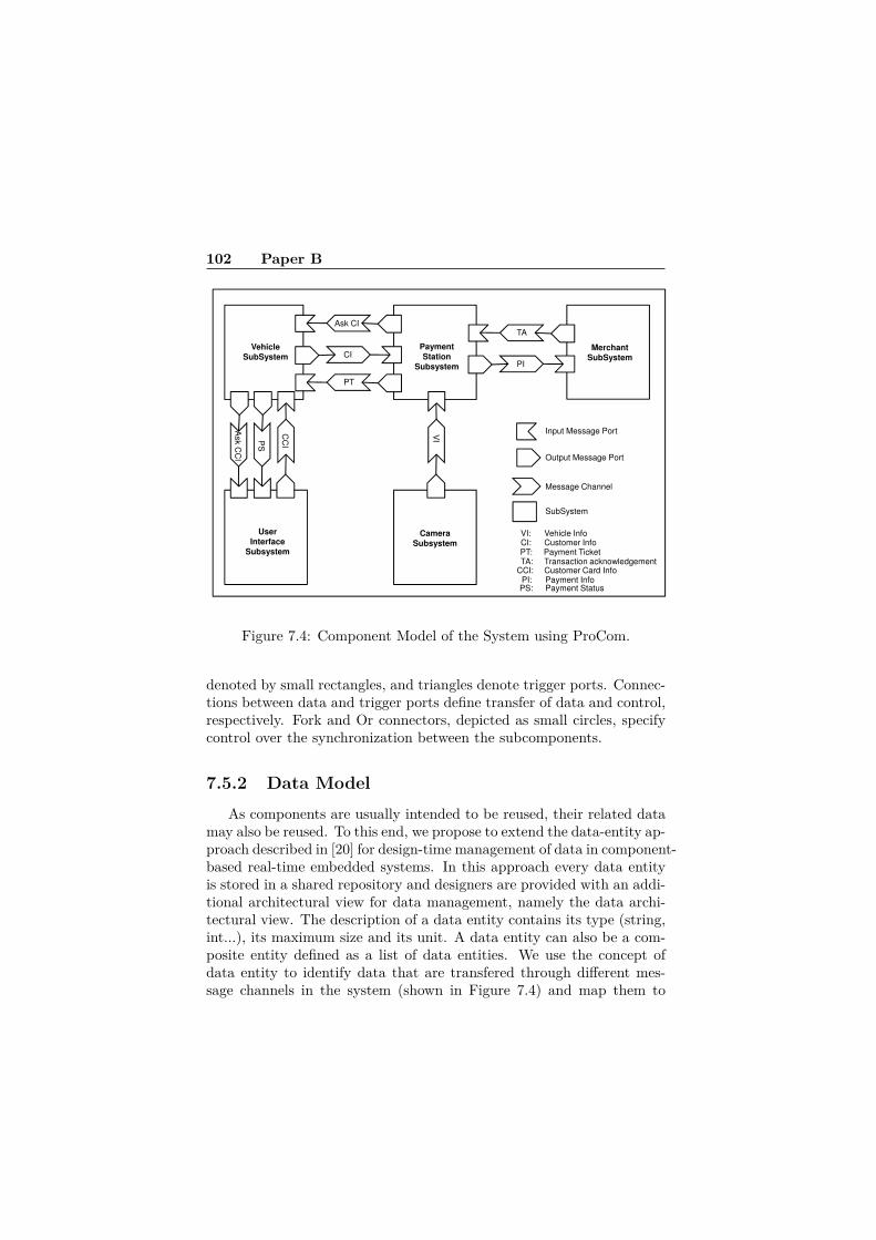
102 Paper B
Input Message Port
MerchantSubSystem
PaymentStation
Subsystem
VehicleSubSystem CI
Output Message Port
CC
I
Ask C
CI
PT
Ask CI
PI
TA
VIP
S
CameraSubsystem
UserInterface
Subsystem
Message Channel
SubSystem
CI: Customer InfoPT: Payment TicketTA: Transaction acknowledgement
CCI: Customer Card InfoPI: Payment InfoPS: Payment Status
VI: Vehicle Info
Figure 7.4: Component Model of the System using ProCom.
denoted by small rectangles, and triangles denote trigger ports. Connec-tions between data and trigger ports define transfer of data and control,respectively. Fork and Or connectors, depicted as small circles, specifycontrol over the synchronization between the subcomponents.
7.5.2 Data ModelAs components are usually intended to be reused, their related data
may also be reused. To this end, we propose to extend the data-entity ap-proach described in [20] for design-time management of data in component-based real-time embedded systems. In this approach every data entityis stored in a shared repository and designers are provided with an addi-tional architectural view for data management, namely the data archi-tectural view. The description of a data entity contains its type (string,int...), its maximum size and its unit. A data entity can also be a com-posite entity defined as a list of data entities. We use the concept ofdata entity to identify data that are transfered through different mes-sage channels in the system (shown in Figure 7.4) and map them to

7.5 Implementation 103
C1
C2
Subsystem E
(a) (b)
Figure 7.5: ProCom SubSystem Implementation.
their respective security concerns (e.g., if they need to be encrypted andprotected or not). Table 7.1 and Table 7.2 show the data entities in ourexample. As described in the last section, subsystems communicate
Table 7.1: Primitive Data Entities.
Data Entity Type Max Size UnitCCNumber String 16 byte
ExpirationDate String 4 byteAskCI Empty 0 byte
AskCCI Empty 0 bytePaymentStatus boolean 1 byteVehicleNumber String 20 byte
VehicleType Enum 8 byteAmountToPay float 4 euro
through asynchronous message passing represented by message chan-nels. A message channel is associated with a list of data entities whichdefines the message content. Table 7.3 presents the mapping betweenmessage channels and data entities for our example. We can observethat the same data entity can be used several times in different mes-sage channels. The mapping between data ports of message ports anddata entities is based on naming convention which enables to distinguishbetween the data ports that require to encrypt/decrypt their data andthose that do not. We call data model the set of data entities which are

104 Paper B
Table 7.2: Composite Data Entities.
Data Entity ContainsCreditCard CCNumber, ExpirationDate
CustomerInfo VehicleNumber, CreditCardPaymentTicket AmountToPay, PaymentStatus
PaymentRequest AmountToPay, CreditCard
Table 7.3: Mapping between Data Entities and Message Channels.
Message Channel Data EntitiesAskCI AskCI
CI CustomerInfoPT PaymentTicket
AskCCI AskCCIPS PaymentStatus
CCI CreditCardVI VehicleNumber, VehicleTypeTA CCNumber, AmountToPay, PaymentStatusPI PaymentRequest
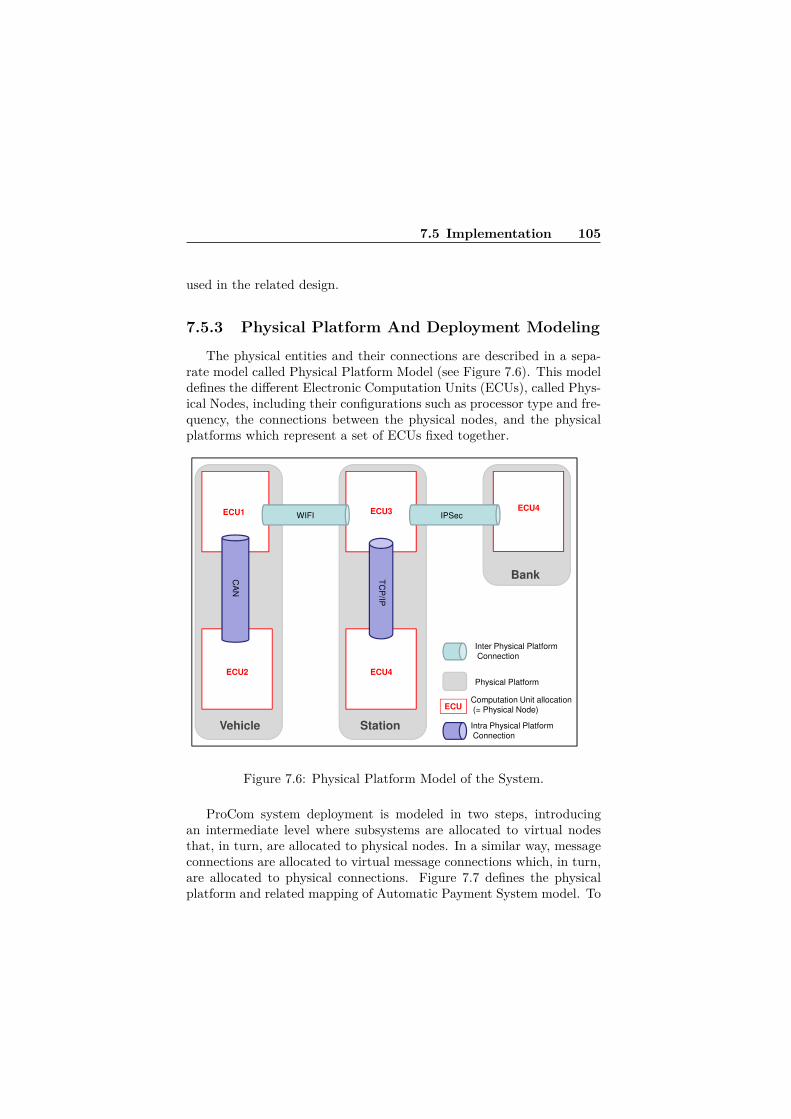
7.5 Implementation 105
used in the related design.
7.5.3 Physical Platform And Deployment Modeling
The physical entities and their connections are described in a sepa-rate model called Physical Platform Model (see Figure 7.6). This modeldefines the different Electronic Computation Units (ECUs), called Phys-ical Nodes, including their configurations such as processor type and fre-quency, the connections between the physical nodes, and the physicalplatforms which represent a set of ECUs fixed together.
Bank
ECU1 ECU3ECU4
CA
N
TC
P/IP
WIFI IPSec
Inter Physical PlatformConnection
Physical Platform
Vehicle Station
ECU4ECU2
ECUComputation Unit allocation(= Physical Node)
Intra Physical PlatformConnection
Figure 7.6: Physical Platform Model of the System.
ProCom system deployment is modeled in two steps, introducingan intermediate level where subsystems are allocated to virtual nodesthat, in turn, are allocated to physical nodes. In a similar way, messageconnections are allocated to virtual message connections which, in turn,are allocated to physical connections. Figure 7.7 defines the physicalplatform and related mapping of Automatic Payment System model. To

106 Paper B
simplify the example, we assume a one to one mapping between virtualnode and physical node.
Merchant
SubSystem
Payment
StationSubsystem
VehicleSubSystem
PT
PI
TA
Bank
CI
Ask CI
WIFI IPSec
ECU1 ECU3 ECU4
VI
CC
I
Ask C
CI
PS
CA
N
TC
P/IP
Camera
Subsystem
User
Interface
Subsystem
Inter Physical PlatformConnection
Physical Platform
Vehicle Station
ECU4ECU2
ECUComputation Unit allocation(= Physical Node)
Intra Physical PlatformConnection
Figure 7.7: Deployment Model of the System depicting allocation toPhysical Platforms.
7.5.4 Security PropertiesInstead of defining the security properties on the architecture, i.e.
the component model, we propose to annotate the data model and com-pute the required security properties on the architecture, based on thesesecurity requirements. It is an original part of our approach where adesigner can think about sensitive data without considering the archi-tecture models. The designer applies security properties to identify andannotate sensitive data in the system, which require to be protectedusing some security mechanisms (e.g., confidentiality and encryption,authentication, integrity, etc.). We consider two types of security prop-erties:
• Confidentiality ensures that the considered information cannot
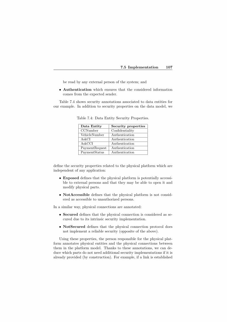
7.5 Implementation 107
be read by any external person of the system; and
• Authentication which ensures that the considered informationcomes from the expected sender.
Table 7.4 shows security annotations associated to data entities forour example. In addition to security properties on the data model, we
Table 7.4: Data Entity Security Properties.
Data Entity Security propertiesCCNumber ConfidentialityVehicleNumber AuthenticationAskCI AuthenticationAskCCI AuthenticationPaymentRequest AuthenticationPaymentStatus Authentication
define the security properties related to the physical platform which areindependent of any application:
• Exposed defines that the physical platform is potentially accessi-ble to external persons and that they may be able to open it andmodify physical parts.
• NotAccessible defines that the physical platform is not consid-ered as accessible to unauthorized persons.
In a similar way, physical connections are annotated:
• Secured defines that the physical connection is considered as se-cured due to its intrinsic security implementation.
• NotSecured defines that the physical connection protocol doesnot implement a reliable security (opposite of the above).
Using these properties, the person responsible for the physical plat-form annotates physical entities and the physical connections betweenthem in the platform model. Thanks to these annotations, we can de-duce which parts do not need additional security implementations if it isalready provided (by construction). For example, if a link is established

108 Paper B
using mere TCP/IP, it is annotated as NotSecured, while in case thatIPSec protocol suite is used for a link, that link is annotated as Secured.This means that the link is considered trusted and already secured, andno security component is necessary to be added for the link. Table 7.5shows the security properties of Automatic Payment System physicalplatforms.
Table 7.5: Security Properties of Physical Entities.
Physical Platform or Connection Security propertiesVehicle ExposedStation NotAccessibleBank NotAccessibleWIFI NotSecuredIPSec SecuredTCP/IP NotSecuredCAN NotSecured
7.5.5 Cost of Security ImplementationsDifferent encryption/decryption algorithms as security mechanisms canbe selected to satisfy the identified security properties in the system.Considering the fact that each security mechanism in the system hasits own costs in terms of timing and performance, power consumptionand so on, choosing an appropriate security mechanism is critical inorder to ensure the satisfaction of timing requirements of the system.For this purpose, and to take into account the timing costs of differentsecurity mechanisms, we rely on the results of studies such as [18] thathave performed these cost measurements. Based on such methods, weassume the existence of such timing measurements for the platforms usedin our system in the form of the Table 7.6. We assume that executiontimes can be computed knowing the target platform, algorithm, key sizeand data size. A timing estimation toolkit may also be provided whichprovides execution time estimates based on these measurements. Ascan be observed from the table, we also take into account and add thisflexibility that some algorithms may not be supported on some platforms(marked as NS).

7.5 Implementation 109
Table 7.6: Execution times and strength ranking of different securityalgorithms for a specific platform
Strength Rank Algorithm Key Size ET-P1 ET-P2 ET-Pn1 AES 128 NS 480 . . .2 3DES 56 292 198 . . .3 DES 56 835 820 . . .
. . .(ET-Px: Executime Time on Platform x in bytes per second, NS: Not Supported on corresponding
platform)
7.5.6 Security Implementation StrategyAs mentioned previously, based on the selected strategy, a security
mechanism is chosen from the table and the components implementingit are added to the component model. The user can then perform timinganalysis on the derived component model to ensure that the overall tim-ing constraints hold and are not violated. We propose several strategiesto help choosing among all possible security implementations:
• The StrongestSecurity strategy selects the strongest security im-plementation available on the platforms (taking into account thatsome security mechanisms, namely encryption algorithms here,may not be available and possible on a certain platform, henceselecting the strongest available one);
• The StrongestSecurityAndLimitImplemNb strategy selectsthe strongest security implementation available on the platformswhile ensuring that we use as few as possible different security im-plementations, since each message channel can use a different en-cryption algorithm (finding the most common security implemen-tation which achieves the strongest level in terms of the strengthrankings);
• The LowestExecTime strategy selects the security implemen-tation available on the platforms which has the lowest executiontime;
• The LowestExecTimeAndLimitImplemNb strategy selects thelowest execution time implementation available on the platformswhile ensuring that we use as few as possible different securityimplementations; and

110 Paper B
• The StrongestSecuritySchedulable strategy selects the strongestsecurity implementation available on the platforms where the sys-tem remains schedulable.
The selection is driven by the fact that the same algorithm must beused for the sender and receiver components which may be deployed ondifferent platforms which in turn may not support the same algorithms.
7.5.7 Transformation
The transformation is performed in four steps:
1. First, we identify the part of a message which needs to be confi-dential or authenticated while considering on which communicationchannels they are transferred;
2. Next, we add components in charge of the encryption and decryp-tion of the identified communication channels;
3. Then, the strategies are used to choose which encryption algorithmto use and generate the code of the added components; and
4. Finally, the Worst Case Execution Time (WCET) of added com-ponents is estimated.
The transformation aims to ensure that data decryption is performedonce and only once before that data will be consumed and that dataencryption is performed once and only once when a message should besent. To illustrate the algorithm, let’s consider the example in Figure 7.8.We assume that only data D1 needs to be confidential. The pseudoalgorithm of the transformation is described in Listing 7.1.

7.5 Implementation 111
(a) Before transformation, no security
C2
C1
C2
D1
D1
C1D2
D2
D2
C2
(b) After transformation, secured system
C1
C2
EnD1
Original elementsGenerated elements
ED1
ED1 DeD1
C1
Digest
Digest
D2
D2
D2
Figure 7.8: Transformation.
Listing 7.1: Transformation Pseudo AlgorithmmsgToSecure = {}f o r a l l channe l s M in component model {P = M. a l l oca tedPhys i ca lChanne l ;i f ( (M. ge tConf ident ia lData ( ) <> {}) or
(M. getAuthet icatedData ( ) <> {}) and(P. i sNotSecured ( ) ) and( (P. i s I n t r aP l a t f o rm ( ) and
P. sourcePort . p lat form . isExposed ( ) ) or(P. i s I n t e rP l a t f o rm ( ) ) )
add M in msgToSecure ;}
f o r a l l M in msgToSecure {P = M. a l l oca tedPhys i ca lChanne l ;
Source = M. sourcePort ;EnD = cr ea t e component
with same por t s as Source ;i f (M. getAuthet icatedData ( ) <> {})

112 Paper B
add one output port Digest to EnDadd one input port Digest to Source
EnD. inConnect ions = Source . inConnect ions ;c r e a t e connect i ons where EnD. outPorts
are connected to cor re spond ingSource . inPort s ;
generate EnD implementation code
Dest = M. destPort ;DeD = cr ea t e component
with same por t s as Dest ;i f (M. getAuthet icatedData ( ) <> {})
add one output port Digest to Destadd one input port Digest to DeD
DeD. outConnect ions = Dest . outConnect ions ;c r e a t e connect i ons where Dest . outPorts
are connected to cor re spond ingDeD. inPort s ;
generate DeD implementation code}
Encryption/Decryption (in EnD1 and DeD1) is done only for confi-dential data while other data are just copied. An additional port is usedto send the digest used for authentication. The decryption component(DeD1) ensures that all message data will be available at the same timethrough the output data ports. This implementation ensures the orig-inal operational semantic of the component model. Then, the securitystrategy is used to choose which encryption/decryption algorithm mustbe used and what its configuration will be.
7.6 Runtime AdaptationThe suggested approach results in a static and fixed set of security mech-anisms to be implemented and used in each invocation and use of thesystem. The system model including the added security components canthen be analyzed in terms of timing properties before reaching the im-plementation phase and therefore it can be evaluated whether the timingrequirements are met or not.
There are, however, cases where such static analysis may not bepossible or even economical. For example, when there is not much timing

7.6 Runtime Adaptation 113
information available about each task in the system to perform timinganalysis, particularly in complex real-time systems with a big numberof different tasks. In such systems even if enough timing information isavailable for each task, due to the complexity and big number of tasks,performing timing analysis may actually be not economical. Moreover,in performing static analysis some assumptions are taken into accountand if those assumptions are violated at runtime then the static analysisresults will not hold anymore. In such situations, a runtime adaptationmechanism can help to cope with the above challenges and mitigatetiming violations by establishing balance between timing and security ina dynamic fashion.
To bring such adaptation mechanism into our approach, we introduceanother strategy called StrongestSecurityAdaptive. By selecting thisstrategy, the implementation of added security components will be syn-thesized as depicted in Figure 7.9.
Main Function
EncryptionAlgorithm n
Encryption Algorithm2
Encryption Algorithm1
Data to
Encrypt
Encrypted Da
ta
Timing behavior
Previous timing behaviors
Timing History Log
Allowed Execution Time(time constraint)
Figure 7.9: Adaptation mechanism.
As shown in Figure 7.9, by using this strategy, in the body of theadded security components (here encryption ones), the implementationof all different possible encryption algorithms will also be included. When

114 Paper B
a request for an encryption arrives, the component firstly tries to use thestrongest possible encryption algorithm (based on the rank of algorithmsin Table 7.6) to encrypt the data. The time it takes to perform the en-cryption is stored in the Timing History Log. If this time is more thanthe specified timing constraint for performing the job, then for the nextencryption, another encryption algorithm with a lower rank but withless execution time will be selected (based on the information in Table7.6).
In case the encryption job completes sooner than the specified timelimit, the unused portion of its time budget is then used to determinewhether it is feasible to adopt a higher ranked algorithm for the nextencryption job or not. With this approach, the feedback that is pro-duced regarding the timing behavior of encryption algorithm is used bythe system to try to adapt itself. Therefore, when the system receivesa burst of processing loads which it cannot fulfill under specified timeconstraints, it adapts itself to this higher load and similarly when theprocessing load decreases, it can gradually go back to using more time-consuming (and presumably more secure) encryption algorithms. Thisdesign is based on the implicit assumption that when it is detected thatan executing encryption algorithm is exceeding its allowed time budget,it is basically more costly to terminate it in the middle of the encryptionprocedure, and restart the encryption of the data with another encryp-tion algorithm, than just letting it finish its job, and instead use one witha lower execution time in the next invocation of encryption components.
The information that is logged in the Timing History Log has thefollowing format: Timestamp, Encryption algorithm, Time constraint,Actual execution time (timestamp, time constraint and actual executiontime are in system ticks unit in the following experiment). An exampleof the generated log information is shown in Table 7.7.
Considering the last row from the log as:
ts, alg, t, e(ts: timestamp, alg: encryption algorithm, t: time constraint, e: actual execution time)
the decision that the system should adopt a lower ranked algorithm ismade using the following formula:
(i) e > t⇒ move down in the encryption algorithms table and selectthe next algorithm with a lower rank.
Also, considering the two log records described as follows:
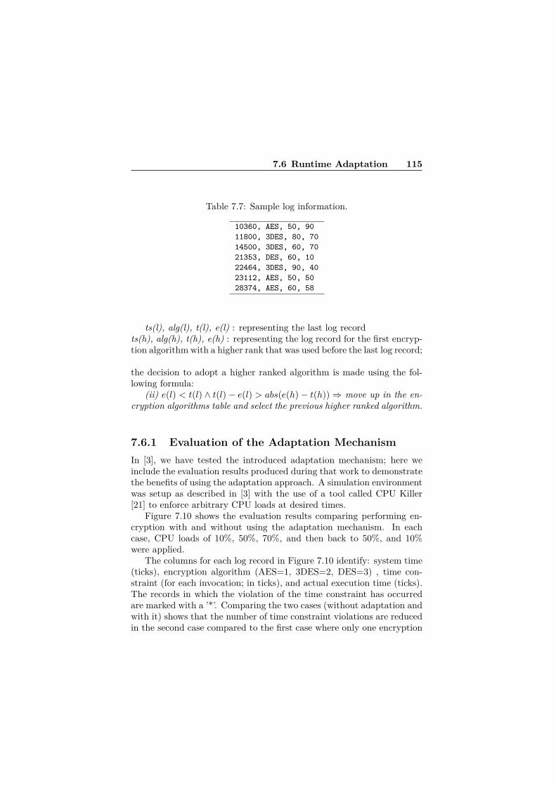
7.6 Runtime Adaptation 115
Table 7.7: Sample log information.
10360, AES, 50, 9011800, 3DES, 80, 7014500, 3DES, 60, 7021353, DES, 60, 1022464, 3DES, 90, 4023112, AES, 50, 5028374, AES, 60, 58
ts(l), alg(l), t(l), e(l) : representing the last log recordts(h), alg(h), t(h), e(h) : representing the log record for the first encryp-tion algorithm with a higher rank that was used before the last log record;
the decision to adopt a higher ranked algorithm is made using the fol-lowing formula:
(ii) e(l) < t(l) ∧ t(l)− e(l) > abs(e(h)− t(h))⇒ move up in the en-cryption algorithms table and select the previous higher ranked algorithm.
7.6.1 Evaluation of the Adaptation MechanismIn [3], we have tested the introduced adaptation mechanism; here weinclude the evaluation results produced during that work to demonstratethe benefits of using the adaptation approach. A simulation environmentwas setup as described in [3] with the use of a tool called CPU Killer[21] to enforce arbitrary CPU loads at desired times.
Figure 7.10 shows the evaluation results comparing performing en-cryption with and without using the adaptation mechanism. In eachcase, CPU loads of 10%, 50%, 70%, and then back to 50%, and 10%were applied.
The columns for each log record in Figure 7.10 identify: system time(ticks), encryption algorithm (AES=1, 3DES=2, DES=3) , time con-straint (for each invocation; in ticks), and actual execution time (ticks).The records in which the violation of the time constraint has occurredare marked with a ’*’. Comparing the two cases (without adaptation andwith it) shows that the number of time constraint violations are reducedin the second case compared to the first case where only one encryption

116 Paper B
Figure 7.10: Performing encryption with and without adaptation.
algorithm (with the highest execution time) is used. Moreover, in thesecond case more number of encryption jobs have been performed undera shorter period of time.
Since the goal with this adaptive strategy is to use the strongest se-curity algorithm possible, the adaptation mechanism assumes that theencryption algorithms in Table 7.6 are sorted according to their execu-tion times resulting in the strongest but most time consuming one to beat the top and the weakest but less timing consuming algorithm at thebottom. Also, as a note for the decryption side, there are different waysto match and synchronize the decryption algorithm with the selectedencryption algorithm. Our suggested way to do this is to add some ad-ditional bits identifying the used encryption algorithm (e.g., through theuse of 2-bit or 3-bit ID numbers, according to the number of different al-

7.7 Discussion 117
gorithms) to the encrypted message for the decryption side to correctlypick and use the appropriate algorithm. Moreover, in the introducedadaptation mechanism and its evaluation, an encryption algorithm andthe respective decryption algorithm for it have been assumed to take thesame amount of time which is generally valid as mentioned in [18]. How-ever, to extend the adaptation approach for distributed systems whereencryption and decryption can be performed on different nodes, moreparameters for making adaptation decisions can be added. Such an ex-tension can be to consider the sum of encryption time and decryptiontime for each algorithm to make adaptation decisions instead of justconsidering the encryption time only.
7.7 DiscussionThis approach has been experimented partially in PRIDE, the ProComdevelopment environment. The feasability at model level of the ap-proach has been validated while the code generation part remains asfuture works. The security annotations have been added using the At-tribute framework[22] which allows to introduce additional attribute toany model element in ProCom. The model transformation has been im-plemented using a QVTo[23] transformation plugged at the end of theprocess described in [24]. These experiments aim to show the benefits atthe design level of the approach where timing properties of the overallsystem can be analysed. The current implementation only supports theLowestExecTime and StrongestSecurity strategies. The StrongestSecu-ritySchedulable strategy is hard to implement, however, it is the mostinteresting one. One of the reasons that we do not claim that we alsoprovide this strategy, in spite of having the execution times of securitycomponents, is that the actual execution times in the synthesized systemwill not necessarily be the sum and individual addition of the executiontimes of the added security components to the rest of the system. Morecomplex security implementation strategies can be considered but arenot covered in this paper.
As for the synthesis of the code of the security components, in orderto keep the approach generic, we intend to let certificate specificationand other specific parameters of encryption algorithm to be filled in thegenerated code. One generator is associated for each algorithm. Thesuitability for timing analysis of the generated component code needs to
118 Paper B
be planned but at least will allow for measurement based timing anal-ysis as any other ProCom component. While the system functionalityremains the same, the system needs also to react to authentication er-rors. This problem could be partially solved by allowing developers toadd code to manage authentication errors in the generated code to definewhat must be the output data in each specific case.
Regarding the runtime adaptation mechanism, while on one hand,it may make the job of the attackers harder as not a fixed algorithm isused in each invocation and thus it will not be known and predictableto the attackers (hence some sort of “security through obscurity”), onthe other hand, if attackers know the internal mechanism of the runtimeadaptation, they can force some processing load on the system to makethe system adopt the weakest algorithm possible, and that way, make iteasier for themselves to break into the system. Moreover, the adaptationmechanism which was used as part of our general approach in this paper,can also be designed to act as an option; in the sense that it can be turnedon and used when a processing load beyond a certain level is detectedand turned off otherwise. This can help to mitigate the overhead of theadaptation mechanism itself (although another mechanism to monitorthe processing load would need to be added in that case) and only useit when there are many requests for encryption.
7.8 Related WorkDesigning security features for real-time embedded systems is a challeng-ing task and requires appropriate methods and considerations. [16] and[25] particularly discuss the specific challenges of security in embeddedsystems and define it as a new dimension to be considered throughoutthe development process. Considering the unique challenges of securityin embedded systems, [25] also emphasizes that new approaches to secu-rity are required to cover all aspects of embedded systems design fromarchitecture to implementation. The methods that we introduced inthis paper contribute towards this goal by applying different disciplinesin the field of software engineering, such as model-driven developmentmethods, to cope with the specific challenges of designing security forembedded systems.
Also as a non-functional requirement [7, 26], satisfying security re-quirements in a system has costs and implications in terms of impact on

7.8 Related Work 119
other requirements such as performance, power consumption and so on.In [17], measurement and comparison of memory usage and energy con-sumption of several encryption algorithms on two specific wireless sensornetwork platforms have been done. Performance and timing comparisonsof several encryption algorithms are offered in [18] where Pentium ma-chines are used as the platform. The approaches we proposed in thispaper, work by relying on the timing and performance comparison re-sults of encryption algorithms in such studies.
While model-driven and component-based approaches serve as promis-ing approaches to cope with the design complexity of real-time embeddedsystems, management of runtime data in these systems has also becomean important issues than ever before due to the growing complexityof them. This fact becomes more clear when we realize that keepingtrack of all data that are passing through different parts of the systemis an extremely hard task for a person. In addition, most design meth-ods based on component models focus mainly on functional structur-ing of the system without considering semantics and meanings for dataflows [20]. A data-centric approach for modeling data as well as usingreal-time databases for runtime data management in real-time embed-ded systems is proposed in [20]. In this work, however, non-functional(extra-functional) properties such as security are not addressed, and ourapproach presented in this paper basically follows a similar method formodeling data entities as a basis to define security specification.
As for modeling security aspects, there are several solutions such asUMLsec [12]. UMLsec is a UML profile [27] for the specification of secu-rity relevant information in UML diagrams. It is one of the major worksin this area and comes with a tool suite which provides the possibilityto evaluate security requirements and their violations. SecureUML [28]is also another UML profile for modeling of role-based access controls.UML profile for Modeling and Analysis of Real-time Embedded Systems(MARTE) [29] provides semantics for modeling non-functional proper-ties and their analysis (e.g., schedulability). In [30], we have discussedMARTE and the benefits of extending MARTE with security annota-tions to better cover the modeling needs of embedded systems. BesidesUMLsec and its tool suite which enables analysis of security require-ments, in [31], a method for specifying security requirements on UMLmodels and verifying their satisfaction by relating model-level require-ments to code-level implementation is offered. In [32], we have provideda small example how it is possible to model security requirements along

120 Paper B
with some other requirements of telecommunication systems and thenperform model-based analysis using the analysis tool suite of UMLsec toidentify possible violations of security requirements.
The need to identify sensitive data is also discussed in [33] wherean extension to include security concerns as a separate model view forweb-services based on Web-Services Business Process Execution Lan-guage (WS-BPEL) is offered. However, it does not take into accountthe consequences of security design decisions on timing aspects, whileby identifying sensitive parts of messages which need to be secured, ourobjective is to ease the computation of the timing impacts of securityimplementations protecting those sensitive data. Considering the chal-lenges of securing distributed systems [34] has done a survey on theapplication of security patterns, as a form of software design patterns,to secure distributed systems. Moreover, it discusses different method-ologies that make use of these ad-hoc security patterns in a structuredway. It also reports that the majority of the studied methodologies lackexplicit support for distributed systems and special concerns that thesesystems have and mentions the development of tailored methodologiesfor different types of distributed systems as an important future workin this area. The approach that we suggested here could serve as anexample for developing such methodologies in particular for distributedreal-time and embedded systems in which timing requirements play akey role in the correctness of the whole system.
Regarding the adaptation method that we used as part of our sug-gested approach, there are also several related studies and approachesthat we discuss them here. The study done in [35] is one of the interest-ing works in the area of security for real-time embedded systems whichuses an adaptive method. In this work, the main focus is on a set ofperiodic tasks with known real-time parameters, whereas, our main tar-get is complex systems that can consist of any type of real-time tasks.Also, while in our work, the security level of the system is consideredimplicitly through the selection of algorithms from the encryption algo-rithms table, in [35], a QoS value has been considered which explicitlyrepresents the security level of the system. Moreover, in our work, it isthe encryption algorithms which are adaptively replaced, while the mainadaptation component in that work is the key length. Our approach caneasily be extended to cover not only different encryption algorithms butalso variations of each, including different combinations of key length,number of rounds and so on, as items (rows) in the encryption algo-

7.9 Conclusion and Future Work 121
rithms table (e.g., AES256, AES128, etc.). Another interesting studywith is close to our work is [36], which basically introduces a similartype of adaptation mechanism as ours. The main focus in that work is,however, on client-server scenarios using a database, and to manage theperformance of transactions. The security manager component used inthis work periodically adjusts the the security level of the system. In ourapproach, however, the adaptation mechanism is executed per requestand is not active when there is no request for encryption. Moreover, itis possible in the approach introduced in this work that an inappropri-ate encryption method is used by a client, while security level changeis occurring. To solve this situation, several acknowledgment messagesare sent and the process is repeated to correct this issue. Therefore, itis possible that the security manager faces problems regarding synchro-nization and message loss due to out of order arrival of messages. Asanother approach for managing security in real-time systems, in [37], asecure-aware scheduler is introduced which basically incorporates andtakes into account timing management of security mechanisms as partof its scheduling policy.
7.9 Conclusion and Future WorkIn this paper, we introduced an approach to define security specificationsin real-time embedded systems at a high level of abstraction based onthe benefits of model-driven and component-based methods. Using thesuggested approach we bring semantics to the data that are transferredin embedded systems to identify sensitive data. The approach enablesalso to derive automatically the security implementations and facilitatesperforming timing analysis including security features at early phasesof development. It was also demonstrated how incorporating a runtimeadaptation mechanism as part of the approach helps to mitigate the vi-olations of timing constraints at runtime. As mentioned, such runtimeadaptation mechanisms are especially useful for complex systems whereperforming static analysis may not be practical, as well as in cases wherethe assumptions that have been used for performing static analysis areprone to deviation and violation at runtime which can then lead to theinvalidation of analysis results. Moreover, the introduced approach helpssystem designers to mainly focus on the system architecture and address-ing timing properties, and at the same, including security concerns in

122 Paper B
the design models without needing much expertise on how to implementsecurity mechanisms. This again contributes to bringing security con-siderations in higher levels of abstraction.
One of the extensions of this work is to define and add more strategiesfor the designers to choose. Among the currently defined strategies, theStrongestSecuritySchedulable is the most interesting one but is hard toimplement and will be part of our future works. One of the reasons thatwe do not claim that we also provide this strategy, in spite of havingthe execution times of security components, is that the actual execu-tion times in the synthesized system will not necessarily be the sum andindividual addition of the execution times of the added security compo-nents to the rest of the system. Also as another idea for the extensionof this work, it would be interesting to define and assign required secu-rity strength to data and message channels as another factor that alsoaffects the selection of security components. It should also be noted thatin this work we mainly addressed encryption as a security mechanism.Considering other mechanisms such as authorization methods and theirimpacts on timing characteristics of systems is another interesting di-rection of this work to investigate. Also including other aspects thantiming, such as power consumption of security mechanisms, performingtrade-off, and establishing balance among them, similar to what we didhere for timing properties, can be another extension of this paper andfuture work.
7.10 AcknowledgementsThis work has been supported by Xdin Stockholm AB [38] and SwedishKnowledge Foundation (KKS) [39] through the ITS-EASY industrialresearch school program [40].

Bibliography
[1] Mehrdad Saadatmand, Antonio Cicchetti, and Mikael Sjödin. OnGenerating Security Implementations from Models of EmbeddedSystems. In The Sixth International Conference on Software Engi-neering Advances (ICSEA 2011), Barcelona, Spain, October 2011.
[2] Mehrdad Saadatmand and Thomas Leveque. Modeling Security As-pects in Distributed Real-Time Component-Based Embedded Sys-tems. In Information Technology: New Generations (ITNG), 2012Ninth International Conference on, pages 437 –444, Las Vegas,USA, april 2012.
[3] Mehrdad Saadatmand, Antonio Cicchetti, and Mikael Sjödin. De-sign of adaptive security mechanisms for real-time embedded sys-tems. In Proceedings of the 4th international conference on En-gineering Secure Software and Systems, ESSoS’12, pages 121–134,Berlin, Heidelberg, 2012. Springer-Verlag.
[4] Premkumar T. Devanbu and Stuart Stubblebine. Software engi-neering for security: a roadmap. In Proceedings of the Conferenceon The Future of Software Engineering, ICSE ’00, pages 227–239,New York, NY, USA, 2000. ACM.
[5] Fu-Hau Hsu, Fanglu Guo, and Tzi-cker Chiueh. Scalable network-based buffer overflow attack detection. In Proceedings of the 2006ACM/IEEE symposium on Architecture for networking and commu-nications systems, ANCS ’06, pages 163–172, New York, NY, USA,2006. ACM.
123

124 Bibliography
[6] Alec Main. Application Security: Building in Security duringthe Development Stage. Journal of Information Systems Security,13(2):31–37, 2004.
[7] Luiz Marcio Cysneiros and Julio Cesar Sampaio do Prado Leite.Non-functional requirements: From elicitation to conceptual mod-els. In IEEE Transactions on Software Engineering, volume 30,pages 328–350, 2004.
[8] Markus Voelter, Christian Salzmann, and Michael Kircher. ModelDriven Software Development in the Context of Embedded Compo-nent Infrastructures. In Colin Atkinson, Christian Bunse, Hans-Gerhard Gross, and Christian Peper, editors, Component-BasedSoftware Development for Embedded Systems, volume 3778 of Lec-ture Notes in Computer Science, pages 143–163. Springer Berlin /Heidelberg, 2005.
[9] Bran Selic. The Pragmatics of Model-Driven Development. IEEESoftware Journal, 20:19–25, September 2003.
[10] M. T örngren, DeJiu Chen, and I. Crnkovic. Component-based vs.model-based development: a comparison in the context of vehicularembedded systems. In Software Engineering and Advanced Appli-cations, 2005. 31st EUROMICRO Conference on, pages 432 – 440,aug.-3 sept. 2005.
[11] Ivica Crnkovic. Component-based Software Engineering - NewChallenges in Software Development. In Software Focus, volume 2,pages 27–33, 2001.
[12] Bastian Best, Jan Jurjens, and Bashar Nuseibeh. Model-BasedSecurity Engineering of Distributed Information Systems UsingUMLsec. In Proceedings of the 29th international conference onSoftware Engineering, ICSE ’07, pages 581–590, Washington, DC,USA, 2007. IEEE Computer Society.
[13] Anders Wall, Johan Andersson, Jonas Neander, Christer Norstr öm,and Martin Lembke. Introducing Temporal Analyzability Late inthe Lifecycle of Complex Real-Time Systems. In Real-Time and Em-bedded Computing Systems and Applications, volume 2968 of LectureNotes in Computer Science, pages 513–528. Springer Berlin Heidel-berg, 2004.

Bibliography 125
[14] Sigrid Gürgens, Carsten Rudolph, Antonio Maña, and SiminNadjm-Tehrani. Security engineering for embedded systems: theSecFutur vision. In Proceedings of the International Workshop onSecurity and Dependability for Resource Constrained Embedded Sys-tems, S&D4RCES ’10, New York, NY, USA, 2010. ACM.
[15] Eirik Albrechtsen. Security vs Safety. NTNU - Norwegian Univer-sity of Science and Technology http://www.iot.ntnu.no/users/albrecht/rapporter/notat%20safety%20v%20security.pdf,Accessed: December 2012.
[16] Paul Kocher, Ruby Lee, Gary McGraw, and Anand Raghunathan.Security as a new dimension in embedded system design. In Pro-ceedings of the 41st annual Design Automation Conference, DAC’04, pages 753–760, 2004. Moderator-Ravi, Srivaths.
[17] Jongdeog Lee, Krasimira Kapitanova, and Sang H. Son. The price ofsecurity in wireless sensor networks. Journal of Computer Networks,54:2967–2978, December 2010.
[18] A. Nadeem and M.Y. Javed. A Performance Comparison of DataEncryption Algorithms. In First International Conference on Infor-mation and Communication Technologies, ICICT 2005., pages 84 –89, 2005.
[19] Séverine Sentilles, Aneta Vulgarakis, Tomas Bures, Jan Carl-son, and Ivica Crnkovic. A Component Model for Control-Intensive Distributed Embedded Systems. In Michel R.V. Chau-dron and Clemens Szyperski, editors, Proceedings of the 11th In-ternational Symposium on Component Based Software Engineering(CBSE2008), pages 310–317. Springer Berlin, October 2008.
[20] Andreas Hjertström, Dag Nyström, and Mikael Sjödin. A data-entity approach for component-based real-time embedded systemsdevelopment. In Proceedings of the 14th IEEE international con-ference on Emerging technologies & factory automation, ETFA’09,pages 170–177, Piscataway, NJ, USA, 2009. IEEE Press.
[21] CPU Killer. http://www.cpukiller.com/, Accessed: December2012.

126 Bibliography
[22] Séverine Sentilles, Petr Štěpán, Jan Carlson, and Ivica Crnković. In-tegration of Extra-Functional Properties in Component Models. In12th International Symposium on Component Based Software En-gineering. Springer, 2009.
[23] Ivan Kurtev. State of the Art of QVT: A Model TransformationLanguage Standard. In Applications of Graph Transformations withIndustrial Relevance, volume 5088 of Lecture Notes in ComputerScience, pages 377–393. Springer Berlin, 2008.
[24] Thomas Leveque, Jan Carlson, Séverine Sentilles, and EtienneBorde. Flexible Semantic-Preserving Flattening of HierarchicalComponent Models. In 37th EUROMICRO Conference on SoftwareEngineering and Advanced Applications (SEAA). IEEE ComputerSociety, August 2011.
[25] Srivaths Ravi, Anand Raghunathan, Paul Kocher, and Sunil Hat-tangady. Security in embedded systems: Design challenges. ACMTransactions on Embedded Computing Systems (TECS), 3:461–491,August 2004.
[26] Mehrdad Saadatmand, Antonio Cicchetti, and Mikael Sjödin. To-ward Model-Based Trade-off Analysis of Non-Functional Require-ments. In 38th Euromicro Conference on Software Engineering andAdvanced Applications(SEAA), September 2012.
[27] B. Selic. A Systematic Approach to Domain-Specific Language De-sign Using UML. In Object and Component-Oriented Real-TimeDistributed Computing, 2007. ISORC ’07. 10th IEEE InternationalSymposium on, pages 2 –9, may 2007.
[28] Torsten Lodderstedt, David A. Basin, and Jürgen Doser. Se-cureUML: A UML-Based Modeling Language for Model-Driven Se-curity. In Proceedings of the 5th International Conference on TheUnified Modeling Language, UML ’02, pages 426–441, London, UK,2002. Springer-Verlag.
[29] MARTE specification version 1.1. http://www.omgmarte.org, Ac-cessed: December 2012.

Bibliography 127
[30] Mehrdad Saadatmand, Antonio Cicchetti, and Mikael Sjödin. Onthe Need for Extending MARTE with Security Concepts. In In-ternational Workshop on Model Based Engineering for EmbeddedSystems Design (M-BED 2011), March 2011.
[31] John Lloyd and Jan Jürjens. Security Analysis of a Biometric Au-thentication System Using UMLsec and JML. In Proceedings of the12th International Conference on Model Driven Engineering Lan-guages and Systems, MODELS ’09, pages 77–91, Berlin, Heidelberg,2009. Springer-Verlag.
[32] Mehrdad Saadatmand, Antonio Cicchetti, and Mikael Sjödin. UML-Based Modeling of Non-Functional Requirements in Telecommuni-cation Systems. In The Sixth International Conference on SoftwareEngineering Advances (ICSEA 2011), October 2011.
[33] Meiko Jensen and Sven Feja. A Security Modeling Approach forWeb-Service-Based Business Processes. In Proceedings of the 200916th Annual IEEE International Conference and Workshop on theEngineering of Computer Based Systems, ECBS ’09, pages 340–347,Washington, DC, USA, 2009. IEEE Computer Society.
[34] Securing distributed systems using patterns: A survey. Computers& Security Journal, 31(5):681 – 703, 2012.
[35] Kyoung-Don Kang and Sang H. Son. Towards security and QoSoptimization in real-time embedded systems. In SIGBED Rev., vol-ume 3, pages 29–34, New York, NY, USA, January 2006. ACM.
[36] Sang H. Son, Robert Zimmerman, and Jörgen Hansson. An adapt-able security manager for real-time transactions. In Proceedingsof the 12th Euromicro conference on Real-time systems, Euromicro-RTS’00, pages 63–70, Washington, DC, USA, 2000. IEEE ComputerSociety.
[37] T. Xie and X. Qin. Scheduling security-critical real-time applica-tions on clusters. In IEEE Transactions on Computers, volume 55,pages 864 – 879, july 2006.
[38] Xdin AB. http://xdin.com/, Accessed: December 2012.

[39] KK-stiftelsen: Swedish Knowledge Foundation. http://www.kk-stiftelsen.org/SitePages/Startsida.aspx, Accessed: De-cember 2012.
[40] ITS-EASY post graduate industrial research school for embed-ded software and systems. http://www.mrtc.mdh.se/projects/itseasy/, Accessed: December 2012.

Chapter 8
Paper C:Monitoring Capabilitiesof Schedulers inModel-DrivenDevelopment ofReal-Time Systems
Mehrdad Saadatmand, Mikael Sjödin, Naveed Ul Mustafa17th IEEE International Conference on Emerging Technologies & Fac-tory Automation (ETFA), Krakow, Poland, September, 2012.
129

Abstract
Model-driven development has the potential to reduce the design com-plexity of real-time embedded systems by increasing the abstractionlevel, enabling analysis at earlier phases of development, and automaticgeneration of code from the models. In this context, capabilities of sched-ulers as part of the underlying platform play an important role. Theycan affect the complexity of code generators and how the model is imple-mented on the platform. Also, the way a scheduler monitors the timingbehaviors of tasks and schedules them can facilitate the extraction ofruntime information. This information can then be used as feedback tothe original model in order to identify parts of the model that may needto be re-designed and modified. This is especially important in orderto achieve round-trip support for model-driven development of real-timesystems. In this paper, we describe our work in providing such mon-itoring features by introducing a second layer scheduler on top of theOSE real-time operating system’s scheduler. The goal is to extend themonitoring capabilities of the scheduler without modifying the kernel.The approach can also contribute to the predictability of applicationsby bringing more awareness to the scheduler about the type of real-timetasks (i.e., periodic, sporadic, and aperiodic) that are to be scheduledand the information that should be monitored and logged for each type.

8.1 Introduction 131
8.1 IntroductionModel-Driven Development (MDD) is a promising approach to cope withthe design complexity of real-time and embedded systems. It helps toraise the abstraction level and also perform analysis at earlier phasesof development. Therefore, problems in the design of a system can beidentified before the implementation phase [1].
Automatic code generation is also one of the end goals in model-driven development. In the context of real-time systems, this includesgenerating the implementation of periodic, sporadic and aperiodic tasks.However, most (industrial) Real-Time Operating Systems (RTOS) suchas VxWorks, RTEMS, RT-Linux, Windows CE, OSE, and also otherssuch as FreeRTOS only allow specification of priority for a real-timetask. The definition of different types of real-time tasks (i.e., periodic,sporadic, and aperiodic) and specification of timing properties for themincluding period, deadline, Worst-Case Execution Time (WCET), etc.are not explicitly supported in these RTOSes. While in theory, a real-time task is simply specified by its timing parameters, in practice andwhen it comes to implementation, these parameters are introduced inthe system in different ways. For example, a periodic task may be im-plemented in the form of an interrupt while its period is actually set byhaving a timer to trigger the interrupt periodically. For code genera-tion, this means that for every model element defined as periodic, whatis actually generated is an interrupt handler that behaves in a periodicway. The issue is that when we look at these systems at runtime, notangible and single runnable entity as a real-time periodic task is actu-ally observable and identifiable. In other words, the semantic mappingof a periodic task at model level and such an entity at runtime becomesweak.
Moreover, other parameters of a real-time task such as deadline arelost and not present at the implementation level or are defined in arbi-trary and different ways in each implementation. This is because amongall these parameters, what is usually supported explicitly by most real-time operating systems, is to specify only priority for a task. Otherparameters are left to be defined and implemented by system designersin arbitrary ways, such as using timer interrupts and delays to enforce pe-riodicity or Minimum Inter-Arrival Time (MIAT). The problem becomeseven more evident when it comes to runtime monitoring of real-time sys-tems and where a system needs to detect events such as deadline misses,

132 Paper C
execution time overruns, etc.To cope with these problems, we propose a second layer scheduler
which takes as input the specification and implementation of real-timetasks including all of their temporal parameters, and schedules and ex-ecutes them using the underlying scheduler of the operating system.With this design, the code generators can then generate tangible real-time tasks according to a well-defined specification (e.g., definition of atask as: task(task type, period, deadline, execution time)), regardless ofwhether, for instance, they are going to be actually implemented as atimer interrupt or some other mechanism. This way, an actual real-timetask along with its parameters will be present and identifiable at the codelevel. The system can then be easily queried, for example, for the num-ber of periodic or sporadic tasks and their specified timing parameterssuch as deadline. The top-level scheduler schedules a task and uses itsparameters to manage and report events such as deadline misses or exe-cution time overruns. In this approach, even if the underlying platformchanges and the implementation of real-time tasks (e.g., as timer inter-rupt) are modified, it will not require any changes in the code generatorsand also the specification of real-time tasks. This may also improve theportability of the generated code and especially transformation engines,making them as platform-independent [2] as possible.
The issue is that for most commercial or closed-source RTOSes, itmay not be possible or economical to modify the kernel and schedulerto add the above mentioned features. In such scenarios these featurescan be provided through an added layer on top of the core scheduler.In this work, by highlighting the role of schedulers in model-driven de-velopment of real-time systems and to provide round-trip support, wedescribe the suggested second layer scheduler built for OSE real-timeoperating system [3] and demonstrate how it improves the monitoringof the timing behaviors of tasks at runtime and detecting events such asdeadline misses which are critical in real-time systems.
The remainder of the paper is as follows. In Section 8.2, we discussthe background context and motivation of the work. Section 8.3 de-scribes the proposed approach along with its design and implementationdetails. In Section 8.4, an example is demonstrated and the implemen-tation and behavior of the suggested approach is evaluated. In Section8.5 we have a look at the related work, and finally in Section 8.6, wesummarize the work and describe its future extensions and directions.

8.2 Background and Motivation 133
8.2 Background and Motivation
8.2.1 CHESS ProjectThis work has been done in the context of CHESS European project [4].This project is about model-driven and component based developmentof real-time embedded systems for telecommunication, space, railway,and automotive domains which focuses on preservation and guarantee ofextra-functional properties [5]. This is done by performing static analysison design models and monitoring the behavior of the generated systemat runtime. The idea is to back-annotate monitored results back to themodel to inform the designer which modeled features have led to theviolation of specified requirements and may need to be modified. Thegeneral structure of the approach is shown in Figure 8.1.
Figure 8.1: CHESS methodology
As can be seen from the above figure, different types of analysis aredone at different abstraction levels (marked as B, F, and H), and the

134 Paper C
results are propagated back to the model (D). MAST [6] is one of theanalysis tools that is used in CHESS to perform schedulability analysison the model. The system model which is defined in the modeling lan-guage called CHESS ML, is transformed into an appropriate model asinput for the MAST analysis tool.
To ensure that the assumptions based on which the analyses weredone hold true, the system’s execution is monitored and runtime infor-mation are collected. For example, the difference between the charac-teristics of the (ideal) execution environment of the system taken intoaccount for analysis and the actual one when the system is implementedmay lead to the violation of the assumptions that are used to performanalysis [7]. Therefore, monitoring the behavior of the system at runtimeis important in preservation of system properties.
Timing properties are of utmost importance in real-time embeddedsystems. In order to extract and collect information about runtime tim-ing behaviors for back-annotation to the model, the platform should beable to provide this information. Among the most important timingdata for back-annotation that are of interest are deadline misses, actualresponse time, and execution time overruns. However, such a feature isnot present explicitly in many commercial real-time operating systemstoday and needs to be implemented in different ways by system develop-ers. In the scope of this work, we narrow our focus on Part I of Figure8.1.
8.2.2 OSE Real-Time Operating SystemOSE is a real-time operating system developed by Enea [8]. It has beendesigned from the ground up for use in fault-tolerant distributed sys-tems that are commonly found in telecommunication domain, rangingfrom mobile phones to radio base stations and is embedded in millionsof devices around the world [3]. It provides preemptive priority-basedscheduling of tasks. OSE offers the concept of direct and asynchronousmessage passing for communication and synchronization between tasks,and OSE’s natural programming model is based on this concept. Linx,which is the Interprocess Communication Protocol (IPC) in OSE, allowstasks to run on different processors or cores, utilizing the same message-based communication model as on a single processor. This program-ing model provides the advantage of not needing to use shared memoryamong tasks.

8.2 Background and Motivation 135
The runnable real-time entity equivalent to a task is called processin OSE, and the messages that are passed between processes are re-ferred to as signals (thus, the terms process and task in this paper canbe considered interchangeable). Processes can be created statically atsystem start-up, or dynamically at runtime by other processes. Staticprocesses last for the whole life time of the system and cannot be ter-minated. Types of processes that can be created in OSE are: interruptprocess, prioritized process, background process, and phantom process.One interesting feature of OSE is that the same programming model isused regardless of the type of process. Of the timing properties thatwe have been discussing so far, only priority can be assigned for prior-itized processes. Periodic behavior can be implemented by using timerinterrupt processes. Information such as task completion time, deadlinemisses and such, is not reported by default and it needs to be imple-mented using system level APIs for events such as process swap_in andswap_out which are triggered when a process starts and stops running(i.e., context switches).
8.2.3 GoalFigure 8.2 shows the target system that is built in the scope of this work.As discussed before, most real-time operating systems, such as OSE,only allow specification of priority for real-time tasks. In other words,semantically, there is no parameter or kernel level value that representsdeadline, execution time, or period of a task. Similarly, the monitoringinformation and logs that are generated by the system do not containinformation about deadline misses, or execution time overruns, becausethese concepts are not actually understood by the kernel and have nomeaning for it. Therefore, it is the job of a programmer to implementsuch features and collect information by also implementing event han-dlers that monitor when a task gets CPU time and when it is preempted,and then calculate deadline misses or execution time overruns throughthis information.
The proposed solution that is shown in Figure 8.2 solves this situationby introducing a second layer scheduler. The interface to this schedulerlayer representing the specification of a real-time task is in the form of:Task(release time, period/MIAT, execution time, relative deadline, tasktype). Considering these parameters, the second layer scheduler thenschedules the tasks using the priority-based scheduling mechanism of

136 Paper C
Figure 8.2: Interfaces between different parts in the suggested approach
the core scheduler.The code generator on the other hand, generates real-time tasks
(from the model) according to this specification, and need not care howsuch a task is actually implemented on the core scheduler, hence moreportability and re-usability of the analyzed model and generated codeare obtained.
From the monitoring perspective, since the second layer scheduler isresponsible for scheduling tasks according to the described specification,it is aware of concepts such as deadline, and can therefore, produce loginformation representing events such as deadline misses. This generatedlog information from the second layer scheduler can then be used topropagate necessary information back to the model.
We believe that the suggested added layer in our approach can alsohelp with decreasing the gap between theoretical aspects of real-timesystems and their actual implementations by providing more semanticsto parameters and specifications of real-time tasks at implementationlevel and thus increasing the applicability of theoretical knowledge such

8.3 Scheduler Design and Implementation 137
as schedulability analysis techniques.
8.3 Scheduler Design and ImplementationIn this section, the internal mechanism and design details of the secondlayer scheduler are described.
The second layer scheduler developed on top of OSE, schedules agiven set of tasks (S) by releasing tasks to OSE core scheduler accordingto a selected scheduling policy. S can contain three kinds of tasks: Pe-riodic, Sporadic, and Aperiodic tasks. Task parameters such as periodand execution time are generated for the second layer scheduler from themodel as input parameter files with .prm extension.
As shown in Figure 8.3, the system consists of a few other compo-nents besides the second layer scheduler process. At system startup, firstprocess creator is started. Process creator creates an OSE process foreach of the tasks that are specified as a set of input files. Initially, allthese processes will be in the waiting mode (to receive a signal from thesecond layer scheduler process). From this point on, the second layerscheduler process, which has the highest priority in the system, controlsthe system. Based on a specified scheduling policy (e.g., EDF), the sec-ond layer scheduler selects an appropriate task from the queue of waitingtasks, and sends a start signal to it. It then enters a waiting state it-self using OSE receive_w_tmo (receive with timeout) system call. Thissystem call makes the caller process wait until it either receives a signalor the specified timeout expires. We make a specific use of this systemcall in our design by setting its timeout value equal to the time intervalavailable before arrival of a new instance of a higher priority periodictask. Also, whenever a task finishes execution, it sends a completionsignal back to the second layer scheduler process. Therefore, if the run-ning task finishes its job before arrival of the next instance of a higherpriority periodic task, the second layer scheduler will receive a comple-tion signal (at the receive_w_tmo system call), and continues its job(scheduling next tasks). Otherwise, if the running task takes too muchtime, the timeout which is set in the receive_w_tmo command in thesecond layer scheduler will expire, and since the second layer schedulerprocess has the highest priority in the system, it preempts the runningtask, takes the CPU, checks the list of waiting tasks again, and selectsthe next appropriate task to run.

138 Paper C
Right after receiving the completion signal by the second layer sched-uler process, it generates log information about the behavior of the taskwhich has just completed. Since the second layer scheduler has accessto (and thus is aware of) all the real-time parameters of each task (e.g.,periodic/MIAT, deadline, execution time), it can gracefully detect dead-line misses, execution time overruns, and events of this kind, mark themin the log information and report them. This way, all this critical loginformation about the behavior of the system are also centralized, whichcan then be easily queried. This is an important feature which is absentin many real-time operating systems today.
Creation of monitoring log files and persistence of the collected in-formation are done by the monitor process using the information that issent to it by the second layer scheduler process in the form of signals.In this design, two separate log files are actually created: scheduling logfile, and monitoring log file. Scheduling log file contains listing of sched-ules generated by the second layer scheduler by stating the time pointsat which a task in the task set is scheduled, completed or preempted.This log file is generated by the second layer scheduler. Events relatedto task deadlines can be investigated by examining the monitoring logfile generated by the scheduler. Monitoring log file is updated with newinformation only when an instance of a task is completed, and schedulinglog file is updated whenever a task is scheduled, preempted, resumed orcompleted.
The scheduling policy that the second layer scheduler uses for peri-odic tasks is selectable and not fixed. Same is the case with the schedul-ing mechanism for aperiodic and sporadic tasks. The selected policy isread as a configuration value at system startup. This makes the sug-gested approach flexible. Currently Rate Monotonic Scheduling (RMS)and Earliest Deadline First (EDF) policies are supported for periodictasks while aperiodic and sporadic tasks can be scheduled using back-ground [9] or polling server [9, 10] schemes. Other policies can also beadded to design.
In the following sections, the role of different components in our de-sign are described in detail.

8.3 Scheduler Design and Implementation 139
Figure 8.3: Components of Design
8.3.1 System ComponentsProcess Creator
Each task in a task set is specified by two files.
• Parameter File: A file with .prm extension provides task param-eters including release time, period/MIAT, execution time, relativedeadline and type of the task.
Type of task can have four valid values: 0 for Periodic, 1 for Spo-radic, 2 for Aperiodic, and 3 for Polling Server.
• Body File: A file with .c extension contains the body of the task.In other words, .prm file of a task contains its timing non-functionalspecification while .c file contains its functional implementation.

140 Paper C
Process creator reads the parameters for each task from its .prmfile into a data structure, called ”constraints", and creates a prioritizedOSE process against each user defined task. Moreover, It also createsfollowing four OSE prioritized processes:
• Second layer scheduler process
• Sporadic queue holding process
• Aperiodic queue holding process
• Monitor process
None of the created OSE processes is started by process creator ex-cept the second layer scheduler process. Task parameters and ProcessIdentifiers (PIDs) for all processes are then passed to the second layerscheduler in the form of “constraints" data structure.
Second Layer Scheduler
After receiving “constraints" structure and PIDs of all OSE processes cre-ated by process creator, the second layer scheduler schedules the tasksby releasing them to core OSE scheduler according to selected schedulingalgorithm. The design provides options to select between RMS or EDFalgorithm.
To schedule sporadic and aperiodic tasks, the second layer sched-uler supports background scheduling and polling server for schedulingsporadic and aperiodic tasks.
Sporadic Queue Holder
Task set can contain periodic, aperiodic and sporadic tasks. Sporadicqueue holder is a prioritized OSE process which maintains a list of spo-radic tasks waiting for scheduling, by using a queue. Each element ofqueue contains two parameters for a sporadic task: PID correspondingto the given task, and release time of sporadic task.
To release a sporadic task, its PID and release time is to be placed inqueue. An interrupt process (in case of hardware driven sporadic tasks)or a prioritized process (in case of software driven sporadic tasks) mayinitiate this placement by sending a signal to sporadic queue holder.
Upon receiving this signal, sporadic queue holder extracts the PID

8.3 Scheduler Design and Implementation 141
and release time of sporadic task from signal and updates the queue withextracted information.
The second layer scheduler checks if there is a sporadic task to bescheduled by making a query to sporadic queue holder process.
Aperiodic Queue Holder
Aperiodic queue holder has the same structure and mechanism as thesporadic queue holder, except that it maintains a list of aperiodic tasks.Also separate signals are defined for use with aperiodic and sporadicqueue holders.
Monitor
Monitor process generates a log file to state whether specified timingconstraints for each task in task set S are met or not. For example,if the specified MIAT parameter, in case of a sporadic task, is violatedthen monitor records this violation in a monitoring log file.When a task is released to the core OSE scheduler for execution, thesecond layer scheduler observes its timing parameters. As soon as a taskcompletes its execution, the second layer scheduler sends a signal to themonitor process. This signal contains start time, completion time, de-sired deadline, desired execution time, desired MIAT, actual executiontime, and actual MIAT of completed task. These timing values are ex-tracted from .prm file of the task under monitoring (i.e., desired deadlineand execution time) and measured by the second layer scheduler (i.e., ac-tual deadline and execution time). Monitor extracts these timing valuesfrom the received signal and saves the relevant monitoring statements ina monitoring log file.
8.3.2 Signals and Communications
To achieve the scheduling of tasks in a reliable way, several signals aredefined and used by system. These signals play two important roles:carry required data from one component to another, and ensure syn-chronous execution of all components.
These signals are described below.

142 Paper C
• start_exe_sig: Start execution signal. This signal is sent by thesecond layer scheduler to a process to be scheduled on core OSEscheduler. Target process can start execution only if it has receivedstart_exe_sig signal.
• comp_sig: Completion signal. This signal is sent as an acknowl-edgment to the second layer scheduler upon completion by a pro-cess which is created against a user defined task.
• aper_update_sig: Update signal for aperiodic queue holder. Torelease an aperiodic task, an interrupt process or prioritized pro-cess sends the aper_update_sig signal to aperiodic queue holderprocess. This signal contains the PID and release time of an ape-riodic task to be scheduled.This signal is also used as a response to the second layer sched-uler by aperiodic queue holder on receiving start_exe_sig fromscheduler.
• spor_update_sig: Update signal for sporadic queue holder. Torelease a sporadic task, an interrupt process or prioritized processsends the spor_update_sig signal to sporadic queue holder pro-cess. This signal contains the PID and release time of sporadictask to be scheduled.This signal is also used as a response to the second layer schedulerby sporadic queue holder on receiving start_exe_sig from sched-uler.
• qupdate_confirm_sig: Queue update confirmation signal. Thisconfirmation signal is sent back to the sender of an update signal,after receiving aper_update_sig (in case of aperiodic queue holder)or spor_update_sig (in case of sporadic queue holder). Confirma-tion signal informs sender if queue is updated successfully. In caseof failure, sender can send aper_update_sig again with same con-tent after waiting for a finite amount of time.
• monitor_info_sig: Monitoring information signal. This signalis sent by the second layer scheduler to the monitor, every time atask completes its execution. Monitor uses the information con-tained in this signal to determine if a completed task has met itsconstraints, such as deadline and WCET.

8.3 Scheduler Design and Implementation 143
8.3.3 Priority AssignmentIn OSE, there are 32 priority levels. Priority 0 is considered the highestwhile 31 is considered as the lowest priority level. In our system, processcreator creates one OSE process for each task in the input task set. Allsuch processes are assigned priority level of 1. Similarly, sporadic queueholder process and aperiodic queue holder process have priority level of1. However, the second layer scheduler process has priority level of 0which is the highest possible priority level. The reason for assigningpriority level 0 to the scheduler is to make it non preemptable by anyother prioritized OSE process.
Monitor behaves as a background OSE process and hence has thelowest priority level. This ensures that monitoring is performed onlywhen no task is ready and the scheduler is idle. This reduces the effectof monitoring on the scheduling of tasks.
8.3.4 Scheduling of TasksAs described in the previous section, all OSE processes are created byProcess creator but not started by it. Process creator starts only thesecond layer scheduler process and passes “constraints" structure alongwith PIDs of all OSE processes.
Scheduling of Periodic Tasks
The second layer scheduler examines the “type" parameter of all tasksto identify periodic tasks among the task set. Tasks are scheduled byreleasing them to core OSE scheduler according to specified schedulingalgorithm, for example RMS.
The second layer scheduler sends start_exe_sig to the the processrepresenting the user defined task which has highest priority accordingto selected scheduling algorithm. Then scheduler waits for receivingcomp_sig back from target OSE process but with a finite waiting timecalled “timeout".
If comp_sig is received before the timeout is expired, it implies thatthe target process has completed. Hence the second layer scheduler re-leases to the core OSE scheduler the next ready OSE process represent-ing the user defined periodic task. If comp_sig is not received withinthe timeout duration and a process representing a user defined task withhigher priority is ready, then the former process is preempted and second

144 Paper C
layer scheduler releases to core OSE scheduler the process with higherpriority.
Scheduling of Sporadic and Aperiodic Tasks
To schedule a sporadic task, it is necessary that its corresponding PIDand release time are placed in the sporadic processes queue maintainedby sporadic queue holder. This can be achieved by sending a spor_update_sigsignal to the sporadic queue holder containing release time and PID ofthe OSE process corresponding to the task. Signal, spor_update_sig,can be sent to the sporadic queue holder either by an interrupt OSE pro-cess or a prioritized OSE process. In the first case, target sporadic taskbecomes interrupt driven while in second case it behaves as a programdriven sporadic task. The above discussion is valid also for achievinginterrupt and program driven behavior for aperiodic tasks.
Sporadic and aperiodic tasks can be scheduled by using one of fol-lowing two approaches:
• Background Scheme: One approach to schedule sporadic and ape-riodic tasks is to use time slots in which no periodic task is ready torun. In such case, the second layer scheduler first makes query tosporadic queue holder by sending start_exe_sig to find if there isany ready sporadic task. The spor_update_sig signal is sent backby sporadic queue holder to the second layer scheduler, indicatingavailability status of sporadic task.If there is a ready sporadic task, the second layer scheduler re-leases sporadic task to OSE core scheduler and waits until eitherit completes its execution or a periodic task becomes ready. Ifsporadic task is completed and no periodic task is ready to run,second layer scheduler again makes query to sporadic queue holderto find if there are any more sporadic tasks waiting in the queue.If sporadic task queue is empty and no periodic task is ready torun, the second layer scheduler makes query to aperiodic queueholder by sending start_exe_sig. Availability status of aperiodictask is communicated back to the second layer scheduler by sendingaper_update_sig from aperiodic queue holder. If aperiodic queueis not empty and aperiodic task at the head of the queue is readyto run, the second layer scheduler releases that aperiodic task tocore OSE scheduler.
8.3 Scheduler Design and Implementation 145
If there is no periodic, sporadic and aperiodic task to execute,Monitor process is released to core OSE scheduler by the secondlayer scheduler.
• Polling Server Scheme: An alternative approach to schedule spo-radic and aperiodic tasks is to use polling server. Polling server isa periodic task like any other periodic task. It has a period Ps andexecution time Es. Execution time of polling server is known asits budget.Polling server is scheduled along with all other periodic tasks ac-cording to selected scheduling algorithm. However, when pollingserver gets the chance to execute, the second layer scheduler makesquery to sporadic and aperiodic queue holding processes to find ifthere is any ready sporadic or aperiodic task. If sporadic or aperi-odic task is ready to run, the second layer scheduler releases thattask to OSE core scheduler and budget of polling server keeps de-clining per unit time.If sporadic or aperiodic task completes its execution before budgetis expired, the second layer scheduler picks next ready sporadicor aperiodic task to release to OSE core scheduler. This sequencecontinues until either there is no sporadic or aperiodic task or bud-get of server is expired or a higher priority periodic task becomesready to execute.At the start of each period of the polling server, its budget is setequal to its execution time. If at that time point, no sporadic oraperiodic task is ready to run then budget immediately declines tozero. Otherwise the budget decreases one level per time unit.
8.3.5 Monitoring of TasksOn completion of a task, independent of its type, the second layer sched-uler sends monitor_info_sig signal to Monitor. Monitor is implementedas a background OSE process. Hence, it can execute only when there isno periodic, sporadic or aperiodic task ready to run. Monitor continu-ously checks its input message queue for monitor_info_sig signal. Thismessage carries following information to the monitor process regardingcompleted task:
• start time of the task

146 Paper C
• completion time of the task
• specified deadline parameter for the task
• specified MIAT parameter for the task
• specified execution time for the task
• actual execution time for task
• actual deadline for task
• actual MIAT for the task
Monitor uses this information to make decision if a completed task hasmet its parameters or violated them. In any case, monitor records theinformation in a monitoring log file.
Operation of the scheduler is summarized by the sequence diagramof Figure 8.4. In this diagram, the task set consists of two periodictasks T1 and T2, one sporadic task T3 and an aperiodic task T4. Timingparameters of the tasks defined in this task set are listed below using thespecification convention: Task (Release Time, Period, WCET, Relativedeadline, Task type).
Periodic task: T1(0, 12, 3, 8, 0)Periodic task: T2(0, 4, 1, 3, 0)Sporadic task: T3(0, 15, 2, 6, 1)Aperiodic task: T4(0, 0, 1, 6, 2)
This figure shows a valid sequence of execution when RMS is usedas the scheduling policy for periodic tasks, while sporadic and aperiodictasks are scheduled using background scheme. As is evident from thesequence diagram, monitor gets the chance to execute only when noother process is in ready state.
8.4 Experiment and Monitoring ResultsThe described approach has been implemented and tested on OSE Soft-Kernel (SFK) version 5.5.1 [8]. In this section, we show an example of atask set which is implemented based on the specification of the proposedsecond layer scheduler. The way the task set is scheduled and the log

8.4 Experiment and Monitoring Results 147
Figure 8.4: Sequence diagram to demonstrate operation of the scheduler
information that is generated for the behaviour of tasks are illustrated.A task set consisting of four tasks is created. Periodic tasks in the
task set are configured to be scheduled using RMS while aperiodic andsporadic tasks are to be scheduled using polling server scheme (this canbe changed by changing configuration parameters).
Timing constraints for tasks are given below (last parameter identifiesthe type of task):
• T1(0, 10, 2, 5, 3) : Polling server with release time=0, period=10,WCET/Budget=2, Relative Deadline=5, Task type=3.
• T2(0, 5, 2, 4, 0) : Periodic Task with release time=0, period=5, WCET=2,

148 Paper C
Relative Deadline=4, Task type=0.
• T3(0, 5, 2, 4, 1) : Sporadic Task with release time=0, MIAT=5, WCET=2,Relative Deadline=4, Task type=1. Two instances of Sporadic taskT3 are released at time 0;
• T4(0, 0, 2, 7, 2) : Aperiodic Task with release time=0, period= 0(Not Applicable), WCET=2, Relative Deadline=7, Task type=2.
As mentioned before, these timing parameters are actually specifiedin the .prm file of each task (i.e., t1.prm, . . . , t4.prm). Process creatoropens these files and populates ”constraints” data structure with thesedata.
Using the implemented second layer scheduler to schedule this taskset, the following log files are automatically generated:
• Scheduling log file: Scheduling log file provides the time pointsfor each task at which it is scheduled, preempted/not completed,resumed or completed. Parts of the scheduling log informationgenerated for the task set are shown in Listing 8.1. To make iteasier to follow and understand the information in the log file,the PIDs that are assigned to each task by the system are alsomentioned below:
– PID of process representing T1 = 65595.– PID of process representing T2 = 65596.– PID of process representing T3 = 65597.– PID of process representing T4 = 65598.
Listing 8.1: Scheduling log filetask PID=65596Scheduled f o r 5 t i c k s at t i c k s =1115task PID=65596Completed at t i c k s =1117task PID=65597Scheduled with budget= 2 t i c k s at t i c k s =1117task PID=65597Not completed at t i c k s =1119Remaining Execution Time in t i c k s =1task PID=65596Scheduled f o r 5 t i c k s at t i c k s =1120task PID=65596Completed at t i c k s =1122task PID=65596
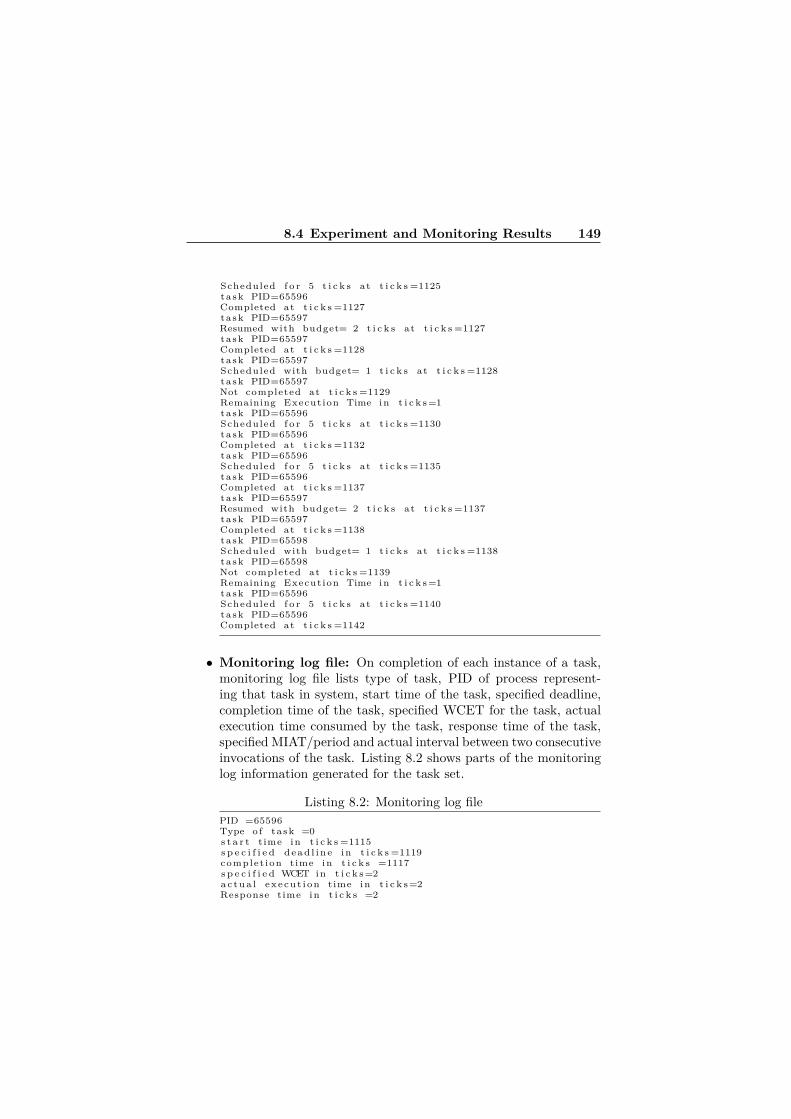
8.4 Experiment and Monitoring Results 149
Scheduled f o r 5 t i c k s at t i c k s =1125task PID=65596Completed at t i c k s =1127task PID=65597Resumed with budget= 2 t i c k s at t i c k s =1127task PID=65597Completed at t i c k s =1128task PID=65597Scheduled with budget= 1 t i c k s at t i c k s =1128task PID=65597Not completed at t i c k s =1129Remaining Execution Time in t i c k s =1task PID=65596Scheduled f o r 5 t i c k s at t i c k s =1130task PID=65596Completed at t i c k s =1132task PID=65596Scheduled f o r 5 t i c k s at t i c k s =1135task PID=65596Completed at t i c k s =1137task PID=65597Resumed with budget= 2 t i c k s at t i c k s =1137task PID=65597Completed at t i c k s =1138task PID=65598Scheduled with budget= 1 t i c k s at t i c k s =1138task PID=65598Not completed at t i c k s =1139Remaining Execution Time in t i c k s =1task PID=65596Scheduled f o r 5 t i c k s at t i c k s =1140task PID=65596Completed at t i c k s =1142
• Monitoring log file: On completion of each instance of a task,monitoring log file lists type of task, PID of process represent-ing that task in system, start time of the task, specified deadline,completion time of the task, specified WCET for the task, actualexecution time consumed by the task, response time of the task,specified MIAT/period and actual interval between two consecutiveinvocations of the task. Listing 8.2 shows parts of the monitoringlog information generated for the task set.
Listing 8.2: Monitoring log filePID =65596Type o f task =0s t a r t time in t i c k s =1115s p e c i f i e d d e a d l i n e in t i c k s =1119complet ion time in t i c k s =1117s p e c i f i e d WCET in t i c k s =2a c t u a l e x e c u t i o n time in t i c k s =2Response time in t i c k s =2

150 Paper C
s p e c i f i e d Period /MIAT in t i c k s =5I n t e r v a l between two c o n s e c u t i v e i n v o c a t i o n s in t i c k s =5PID =65596Type o f task =0s t a r t time in t i c k s =1120s p e c i f i e d d e a d l i n e in t i c k s =1124complet ion time in t i c k s =1122s p e c i f i e d WCET in t i c k s =2a c t u a l e x e c u t i o n time in t i c k s =2Response time in t i c k s =2s p e c i f i e d Period /MIAT in t i c k s =5I n t e r v a l between two c o n s e c u t i v e i n v o c a t i o n s in t i c k s =5PID =65596Type o f task =0s t a r t time in t i c k s =1125s p e c i f i e d d e a d l i n e in t i c k s =1129complet ion time in t i c k s =1127s p e c i f i e d WCET in t i c k s =2a c t u a l e x e c u t i o n time in t i c k s =2Response time in t i c k s =2s p e c i f i e d Period /MIAT in t i c k s =5I n t e r v a l between two c o n s e c u t i v e i n v o c a t i o n s in t i c k s =5PID =65597Type o f task =1s t a r t time in t i c k s =1117s p e c i f i e d d e a d l i n e in t i c k s =1121complet ion time in t i c k s =1128s p e c i f i e d WCET in t i c k s =2a c t u a l e x e c u t i o n time in t i c k s =3Response time in t i c k s =11s p e c i f i e d Period /MIAT in t i c k s =5I n t e r v a l between two c o n s e c u t i v e i n v o c a t i o n s in t i c k s =10PID =65596Type o f task =0s t a r t time in t i c k s =1130s p e c i f i e d d e a d l i n e in t i c k s =1134complet ion time in t i c k s =1132s p e c i f i e d WCET in t i c k s =2a c t u a l e x e c u t i o n time in t i c k s =2Response time in t i c k s =2s p e c i f i e d Period /MIAT in t i c k s =5I n t e r v a l between two c o n s e c u t i v e i n v o c a t i o n s in t i c k s =5PID =65596Type o f task =0s t a r t time in t i c k s =1135s p e c i f i e d d e a d l i n e in t i c k s =1139complet ion time in t i c k s =1137s p e c i f i e d WCET in t i c k s =2a c t u a l e x e c u t i o n time in t i c k s =2Response time in t i c k s =2s p e c i f i e d Period /MIAT in t i c k s =5I n t e r v a l between two c o n s e c u t i v e i n v o c a t i o n s in t i c k s =5PID =65597Type o f task =1s t a r t time in t i c k s =1128s p e c i f i e d d e a d l i n e in t i c k s =1132complet ion time in t i c k s =1138s p e c i f i e d WCET in t i c k s =2

8.4 Experiment and Monitoring Results 151
a c t u a l e x e c u t i o n time in t i c k s =2Response time in t i c k s =10s p e c i f i e d Period /MIAT in t i c k s =5I n t e r v a l between two c o n s e c u t i v e i n v o c a t i o n s in t i c k s =9
The first four lines in the generated scheduling log information shownin Listing 8.1 indicates that the periodic task T2 with PID of 65596,which is started at tick time 1115, has completed at 1117. The next taskwhich is scheduled is T3 with PID of 65597. The polling server has thecapacity of two time unit at this time instance, therefore, the sporadictask T3 can run until tick time 1119, and at 1120 another instance of T2arrives which causes the second layer scheduler to preempt T3. However,at 1119, T3 has not managed to complete its job, and therefore, it ismarked as ’Not completed’.
On the other hand, the monitoring information in Listing 8.2, amongother things, can be used to check whether any deadline miss has oc-curred or not. For example, it shows that the first two instances of T2(PID=65596) have met their deadlines. The first instance has finishedits job at 1117 and finished before its deadline which is 1119. The dead-line for the second instance is at 1124, and it has managed to completeits job at 1122, and therefore, meet its deadline. However, the dead-line of the sporadic task T3, with PID of 65597, has been 1121 whileit has managed to finish its job at 1128. Its actual execution time hasalso been three time units which is one time unit more than its specifiedWCET. This shows that there has been execution time overrun for thistask and there is something wrong with the specified WCET value of it,and it needs to be re-considered. Such information are hardly providedby default in any real-time operating system.
Figure 8.5 visualizes the schedule generated by the scheduler. Thisfigure is created (manually) using the information available in the schedul-ing log file generated by the scheduler. The scheduling log file shows thatthe first task is released at 1115 system ticks. To make this schedule eas-ier to understand in the figure, subtraction of 1115 ticks is performed atevery time point.
As is indicated by a cloud symbol in Figure 8.5, actual executiontime consumed by first instance of sporadic task is 3 ticks instead of 2ticks as specified in timing constraint of WCET=2. Therefore, it missesits deadline of 5 ticks and is completed at 13 ticks. Second instanceof sporadic task is scheduled immediately after completion of the firstinstance. This is because MIAT of 10 ticks is already elapsed (10+2=12).

152 Paper C
Figure 8.5: Schedule generated by the design using second layer scheduler
The diagram in the lower part of Figure 8.5 indicates the replenishmentand decrease of budget with passage of time as is defined for the behaviorof polling servers.
Now that the necessary information about the runtime behavior oftasks is provided in the log files generated by the system, a user can easilyquery them, extract desired parts, and draw conclusions. For example,it is very easy to find out the number of deadline misses, execution timeoverruns, the task with maximum number of deadline misses, etc. byusing the log files as the data source. Similarly, at any time point, thenumber of periodic, sporadic, and aperiodic tasks in the system can eas-ily be requested from the second layer scheduler; a simple but importantfeature which is not provided by default in many RTOSes today. Also,it is now possible to identify and report the time period during whichmaximum number of deadline misses have occurred, and examine as wellhow the system has been behaving in terms of context switches and pre-emptions during that period. These are features whose implementationscan be very hard and complex without having the necessary monitoringinformation and using the suggested approach.

8.5 Related Work 153
8.5 Related WorkMany of the operating systems and also programming languages todayprovide support for measuring the CPU time a runnable entity (i.e.,thread, etc.) consumes to perform its function. However, the monitor-ing facilities and event handling mechanisms provided by these platformsare not usually integrated with their scheduling facilities [11]. As a re-sult, the platform cannot enforce and monitor real-time properties ofthreads such as their allowed execution times and deadlines. Real-TimeSpecification for Java (RTSJ) [11] is introduced to integrate scheduling ofthreads with the execution time monitoring facilities and enforce execu-tion budgets on them in Java. For Ada applications and particularly theAda Ravenscar profile [12] different kernels such as ORK [13] have beenintroduced to enforce and manage task budgets and handle critical real-time events. Moreover, the Ada compiler, GNAT, has defined GNARLas the tasking runtime system of the compiler which is divided into twolayers. The lower layer of GNARL abstracts the execution platform andprovides OS services via POSIX interfaces.
The implementation of different scheduling algorithms on top of afixed priority scheduler has also been used in the FIRST project [14].The main objective in this project has been to develop a schedulingframework for real-time applications that have various types of tasks(hard, soft, firm, etc.) and scheduling paradigms within the same sys-tem to achieve a flexible integrated real-time system. The FRESCORproject [15] which also relies on the results of the FIRST project, targetsthe gap between the real-time theory and the industrial and practicalaspects of real-time systems. In this project a platform independentscheduler called FRSH has been developed which provides a set of APIsfor the applications. FRSH implementation is made portable to differ-ent operating systems using the FRSH Operating System Adaptationlayer (FOSA) which encapsulates all native operating system calls andtypes used by FRSH into neutral names acceptable by both POSIX andnon-POSIX compliant systems [15]. The main objective of this projecthas been to provide a contract-based model and framework for real-timeembedded systems.
The implementation of a new scheduling class called SCHED_DEA-DLINE for the Linux kernel that adds EDF scheduling policy support toLinux is done in[16]. It is also motivated by acknowledging the fact thatdue to limited support for specifying timing constraints for real-time

154 Paper C
tasks (e.g., deadline) and lack of control over them, feasibility studyof the system under development and guaranteeing the timing require-ments of tasks are not possible. There are however several differencesbetween this work and ours. It focuses only on mechanisms for addingEDF scheduling policy to the Linux kernel, while we target the problemin a more general manner and allowing the scheduling policy to be con-figurable. Our focus is mainly on improving the monitoring of real-timeevents by providing more control over real-time tasks and providing moreknowledge about their timing constraints to the scheduler regardless ofthe scheduling policy and without modifying the core scheduler. More-over, we try to provide an abstraction layer around the core schedulerto hide platform-dependent implementation details from the user whileSCHED_DEADLINE tries to solve a different problem and is basicallyadded as a separate module to the system.
One concept which also introduces different levels of abstractionaround a core scheduler is Hierarchical Scheduling Framework (HSF)[17, 10]. There are fundamental differences between what we introducedhere and HSF. HSF is a modular approach in which a system is dividedinto several subsystems. The subsystems are scheduled by a global (core)scheduler, while the tasks in each subsystem are scheduled by local (sub-system) level schedulers. The structure that we introduced here does nottry to divide a system into different subsystems where each of these sub-systems may be scheduled differently by a different scheduler.
There are also studies that focus on execution monitoring of real-time systems. Many of these studies, such as [18], try to predict timingviolations in the system in different ways, for example, using statisticalmodels. Our suggested approach does not to try to predict violationsand produces precise monitoring information for behavior of real-timetasks and violation of timing constraints. The monitoring part in ourapproach is coupled with the scheduler and by bringing awareness tothe scheduler about the type of tasks it is scheduling, monitoring suchinformation becomes a natural and straightforward part of the scheduler.
8.6 Discussion and ConclusionIn this paper, we introduced the concept of the second layer scheduler asan approach to bring semantics and awareness for different types of real-time tasks and their parameters to the scheduler without modifying it.

8.6 Discussion and Conclusion 155
It was shown how this awareness improves the monitoring capabilities ofthe system to help with the detection of critical events such as deadlinemisses, and execution time overruns. While the approach was motivedand described in the context of model-driven development of real-timesystems to enable back-annotation of data and provide round-trip engi-neering support, it does not necessarily need to be used in this contextand the concept of the second layer scheduler is applicable and practicalper se.
Considering a larger set of timing parameters for scheduling of tasksand generating detailed log information in the second layer schedulercan bring along their own overheads. Measurement of these overheadsand evaluation of the price of these added features are left to be doneas a future work. Especially we plan to perform two overhead measure-ments: startup overhead (reading configurations and initializing tasks),and context switch and scheduling decisions overheads. It should how-ever be noted that the actual logging is done by the monitor process inour design which behaves as a background process. The second layerscheduler only sends out a signal (including needed information) to themonitor process and continues its job (asynchronously) without usingany critical section for data sharing by using message passing mecha-nisms of OSE. This way, the overhead of creating log information in thesecond layer scheduler process is tried to be mitigated.
Generation of such detailed monitoring information can also helpwith the predictability of real-time systems at runtime. For instance,even in cases where no deadline misses occur in the system, it becomespossible to observe how close tasks are to missing their deadlines andwhether this gap is decreasing or increasing. Based on such analysisof monitoring information, the system can also adapt itself in order toprevent deadline misses.
One issue that we did not discuss in this paper is the priority inversionproblem. This problem is handled automatically by OSE for communi-cation among periodic tasks, but for sporadic and aperiodic tasks, thepriority inversion issue should be more investigated. Also the way thesystem is designed for the background scheme, periodic tasks will havehigher priority over sporadic tasks, and the priority of sporadic taskswill be higher than aperiodic ones. When the polling server scheme isused, the priority of sporadic tasks will be dependent on the priorityof their periodic server, but still higher than aperiodic ones. This canalso be extended to be configurable by the user. Moreover, in this work,

156 Paper C
since the tasks were assumed to be generated from a model, the taskset was considered to be known and static. We leave the extension ofthe implementation to accept new tasks dynamically as a future work.Also, the possibility to have different numbers and types of servers forsporadic and aperiodic tasks could be another future work.
Since the suggested approach is designed to be flexible in terms of theused scheduling algorithms, it would be interesting as a future directionof this work to investigate the possibility to let the system intelligentlyselect an appropriate/optimal scheduling algorithm based on the require-ments at the model level and generate code accordingly especially thatthe back-annotation mechanism can also be used as a feedback loop.
8.7 AcknowledgementsThis work has been partially supported by the CHESS European Project(ARTEMIS-JU100022) [4] and XDIN AB [19].

Bibliography
[1] Bran Selic. The Pragmatics of Model-Driven Development. IEEESoftware, 20:19–25, September 2003.
[2] A. Kleppe, J. Warmer, and W. Bast. MDA Explained: The ModelDriven Architecture - Practice and Promise. 2003.
[3] Enea. The Architectural Advantages of Enea OSE in Telecom Appli-cations. http://www.enea.com/software/products/rtos/ose/,Last Accessed: February 2012.
[4] CHESS Project: Composition with Guarantees for High-integrity Embedded Software Components Assembly. http://chess-project.ning.com/, Last Accessed: April 2012.
[5] Luiz Marcio Cysneiros and Julio Cesar Sampaio do Prado Leite.Non-functional requirements: From elicitation to conceptual mod-els. In IEEE Transactions on Software Engineering, volume 30,pages 328–350, 2004.
[6] Modeling and Analysis Suite for Real-Time Applications (MAST).http://mast.unican.es/, Last Accessed: February 2012.
[7] S.E. Chodrow, F. Jahanian, and M. Donner. Run-time monitoringof real-time systems. In Real-Time Systems Symposium (RTSS).Proceedings., Twelfth, pages 74 –83, dec 1991.
[8] Enea. http://www.enea.com, Last Accessed: April 2012.
[9] Brinkley Sprunt. Aperiodic Task Scheduling for Real-Time Systems.Technical report, Ph.D. thesis, Carnegie Mellon Univ, 1990.
157

158 Bibliography
[10] Robert Davis and Alan Burns. Hierarchical fixed priority pre-emptive scheduling. In In Proceedings of the 26 th IEEE Interna-tional Real-Time Systems Symposium (RTSS’05), pages 389–398,2005.
[11] Andy J. Wellings, Gregory Bollella, Peter C. Dibble, and DavidHolmes. Cost Enforcement and Deadline Monitoring in the Real-Time Specification for Java. In 7th IEEE International Symposiumon Object-Oriented Real-Time Distributed Computing (ISORC),pages 78–85. IEEE Computer Society, 12-14 May 2004.
[12] Enrico Mezzetti, Marco Panunzio, and Tullio Vardanega. Preserva-tion of Timing Properties with the Ada Ravenscar Profile. In JorgeReal and Tullio Vardanega, editors, Reliable Software Technologies- Ada-Europe 2010, volume 6106 of Lecture Notes in Computer Sci-ence, pages 153–166. Springer Berlin / Heidelberg, 2010.
[13] Juan Zamorano and Jose F. Ruiz. GNAT/ORK: An open cross-development environment for embedded Ravenscar-ADA software.In Proceedings of the 15th IFAC World Congress. Elsevier, 2003.
[14] FIRST Project: Flexible Integrated Real-Time Systems Technology.http://www.frescor.org/index.php?page=related-projects,Last Accessed: April 2012.
[15] FRESCOR Project: Framework for Real-time Embedded Systemsbased on COntRacts. http://www.frescor.org/index.php, LastAccessed: April 2012.
[16] Dario Faggioli, Fabio Checconi, Michael Trimarchi, and ClaudioScordino. An EDF scheduling class for the Linux kernel. In Pro-ceedings of the Eleventh Real-Time Linux Workshop, Dresden, Ger-many, September 2009.
[17] Thomas Nolte, Moris Behnam, Mikael Åsberg, Reinder Bril, andInsik Shin. Hierarchical Scheduling of Complex Embedded Real-Time Systems. In École d’Éte Temps-Réel (ETR’09), pages 129–142, August 2009.
[18] Yue Yu, Shangping Ren, and Ophir Frieder. Prediction of TimingConstraint Violation for Real-Time Embedded Systems with Known
Transient Hardware Failure Distribution Model. In Real-Time Sys-tems Symposium, 2006. RTSS ’06. 27th IEEE International, pages454 –466, dec. 2006.
[19] XDIN AB. http://ny.xdin.com/om-xdin/enea-experts/, Ac-cessed: June 2012.


Chapter 9
Paper D:An AutomatedRound-trip SupportTowards DeploymentAssessment inComponent-basedEmbedded Systems
Federico Ciccozzi, Mehrdad Saadatmand, Antonio Cicchetti, Mikael SjödinThe 16th International Symposium on Component-Based Software En-gineering (CBSE), Vancouver, Canada, June, 2013.
161

Abstract
Synergies between model-driven and component-based software engi-neering have been indicated as promising to mitigate complexity in de-velopment of embedded systems. In this work we evaluate the usefulnessof a model-driven round-trip approach to aid deployment optimization inthe development of embedded component-based systems. The round-tripapproach is composed of the following steps: modelling the system, gen-eration of full code from the models, execution and monitoring the codeexecution, and finally back-propagation of monitored values to the mod-els. We illustrate the usefulness of the round-trip approach exploiting anindustrial case-study from the telecom-domain. We use a code-generatorthat can realise different deployment strategies, as well as special moni-toring code injected into the generated code, and monitoring primitivesdefined at operating system level. Given this infrastructure we can eval-uate extra-functional properties of the system and thus compare differentdeployment strategies.

9.1 Introduction 163
9.1 IntroductionComplexity of embedded systems is continuously increasing and there-fore solicits the introduction of more powerful and automated develop-ment mechanisms able to mitigate it. In this direction, Model-Driven En-gineering (MDE) [1] and Component-Based Software Engineering (CBSE)[2] can be considered as two orthogonal ways of reducing developmentcomplexity through different means. The former shifts the focus of thedevelopment from hand-written code to models from which the imple-mentation is meant to be automatically generated through the exploita-tion of model transformations. The latter breaks down the set of desiredfeatures and their intricacy into smaller replaceable sub-modules, namelycomponents, starting from which the application can be built-up and in-crementally enhanced. Moreover, their combination has been recognisedas an enabler for them to definitely break through for industrial devel-opment of embedded systems [3].
In this research work we exploit the synergy between MDE and CBSEto demonstrate the benefits of an automated round-trip support in aid-ing deployment optimization when developing embedded systems. Theround trip support consists of the following steps:• Modelling: the first step is represented by modelling the systemthrough a structural design, in terms of components, a behaviouraldescription by means of state-machines and action code, as well asa deployment model describing the allocation of software compo-nents to operating system’s processes;
• Code generation: from the information contained in the designmodel, we automatically generate full functional code. Note thatin the paper we refer to generated code as full or full-fledged if itis entirely generated in an automated manner and does not requiremanual tuning in order to be executed on the selected platform;
• Monitoring: after the code has been generated we monitor its ex-ecution on top of the target platform and measure selected Extra-Functional Properties (EFPs). In fact, in modern complex em-bedded systems, certain EFPs cannot be accurately predicted atmodelling level, hence requiring measurements at runtime. Thiswould be the case, e.g., of performance-related EFPs, that oftenonly emerge in a running product. As example, let us consider twosorting algorithms that speed up a program because they use a bigportion of the main memory. Although both increase the perfor-

164 Paper D
mance in isolation and they have no direct functional interaction,in combination they may degrade the overall performance becauseboth share the same (too small) main memory [4];
• Back-propagation: at this point, gathered values are back-propagatedto the design model and, after their evaluation, the deploymentconfiguration can be manually tuned to generate more resource-efficient code.
The round-trip support and its usefulness in aiding the preservation ofEFPs1 from models to generated code have been already proven anddiscussed in [5] and [6]. Nevertheless, their limited support for platformconfigurations (i.e., only single-process) prevented their employment fordeployment issues. The approach has been therefore enhanced in orderto enable synthesis of design models to either a single-process or to aset of communicating processes. This gives flexibility to generate ei-ther highly resource efficient (in terms of inter-system communications)single-process systems or exploit multi-process configurations that could,e.g., run in parallel on multicores and/or maintain error encapsulationwithin one process.
In this work we describe the enhancements made to the round-tripsupport and how it can employ measurements gathered at system im-plementation (or runtime) level towards deployment optimization whendeveloping embedded systems. More specifically, in order to enhancethe generation of full code from models addressing multiprocess appli-cations, additional modelling artefacts (e.g., deployment model) had tobe considered, higher variability of the transformation process had tobe addressed by enhancing the code generation transformations as wellas expanding the intermediate metamodels to entail deployment infor-mation and diverse communication patterns. In order to employ theapproach for deployment assessment the execution platform had to bemodified for enabling monitoring facilities and back-propagating trans-formations were implemented too. Moreover, the approach has beenvalidated against industrial case-studies from the telecom-domain.
The remainder of the paper is structured as follows. The scope ofthe paper is defined in terms of context delimitation and contributionformalisation in Section 9.2. The state-of-the-art related to similar ap-proaches with focus on back-propagation features, monitoring activitiesand deployment optimization based on measurements at system imple-
1By preservation of EFPs we intend keeping them within their validity rangesand protect them from violation at runtime.

9.2 Context 165
mentation level is described in Section 9.3. A running example in termsof an industrial case-study is introduced in Section 9.4 while the proposedsolution is described in Section 9.5. The application of the proposed ap-proach to the example is described in all its details in Section 9.6 withfocus on showing how the round-trip support can aid the developer intaking deployment decisions. Section 9.7 proposes a discussion on theproposed solution and possible enhancements; the paper is then con-cluded by a summary in Section 9.8.
9.2 ContextFollowing the MDE paradigm, a system is developed by designing mod-els and refining them starting from higher and moving to lower levels ofabstraction until code is generated; refinements are performed throughtransformations between models. A model transformation translates asource model to a target model while preserving their well-formedness [7].Since a model is an abstraction of the system under development, rulesand constraints for building it have to be properly described througha corresponding language definition. In this respect, a metamodel de-scribes the set of available concepts and well-formedness rules a correctmodel must conform to [8].
Since different nuances of the CBSE-related terminology can be foundin the literature, in this work we refer to component-based developmentas prescribed by the UML Superstructure [9]. That is to say, a systemis modelled as an assembly of components communicating via requiredand provided interfaces exposed by ports, where a port represents aninteraction between a classifier instance and its internal or external envi-ronment. Additionally, features owned by required interfaces are meantto be offered by one or more instances of the owning classifier to one ormore instances of the classifiers in its internal or external environment.
A fairly wide variegation of different approaches to the measurementof EFPs at system implementation level exists. In this work we focuson runtime monitoring, that represents a method to observe the exe-cution of a system in order to determine whether its actual behaviouris in compliance with the intended one. In comparison to other veri-fication techniques such as static analysis, model checking, testing andtheorem proving which are used mainly to determine “universal correct-ness” of software systems, runtime monitoring focuses on each instance

166 Paper D
and current execution of a system [10].In the following sections we describe the scope of the proposed solu-
tion in terms of modelling language, target platform and intended con-tribution.
9.2.1 CHESS Modelling Language
In our work we employ the CHESS modelling language (CHESS-ML) [11],defined within the CHESS project (cf. Acknowledgements) as a UMLprofile, including tailored subsets of SysML and MARTE profiles. CHESS-ML allows the specification of a system together with relevant EFPssuch as predictability, dependability and security. Moreover, it supportsa development methodology expressly based on separation of concerns;distinct design views address distinct concerns. In addition, CHESS ac-tively supports component-based development as prescribed by the UMLSuperstructure [9].
According to the CHESS methodology, functional and extra-functionalcharacteristics of the system are defined in specific separated views asfollows:• Functional: UML component and composite component diagramsare employed to model the structural aspects of the system whilestate-machines and activity diagrams are used to express functionalbehaviour. Action Language for Foundational UML (ALF) [12] isused to enrich the behavioural description. In this way, we reachthe necessary expressive power to be able to generate full imple-mentation code directly from the functional models with no needfor manual fine-tuning of the code after its generation;
• Extra-functional: in compliance with the principle of separation ofconcerns adopted in CHESS, the functional models are decoratedwith extra-functional information thereby ensuring that the defi-nition of the functional entities is not altered. In respect to theback-propagation proposed in this work, it is worth clarifying thatthere is no cloning nor versioning of the design model but rathera decoration in terms of values updates on the extra-functionalstereotypes. This means that, at each iteration, the EFPs are up-dated and, if any modification to the model is manually performed,no history of previous versions is kept.

9.2 Context 167
9.2.2 OSE Real-Time Operating System
OSE is a commercial and industrial real-time operating system developedby Enea [13] which has been designed from the ground specifically forfault-tolerant and distributed systems. It is widely adopted mainly intelecom-domain and systems ranging from mobile phones to radio basestations [14]. OSE provides the concept of direct and asynchronousmessage passing for communication and synchronisation between tasks,and its programming model is based on this concept. This allows tasksto run on different processors or cores, utilising the same message-basedcommunication model as on a single processor. This programming modelprovides the advantage of avoiding the use of shared memory amongtasks. In OSE, the runnable real-time entity equivalent to a task iscalled process, and the messages that are passed between processes arereferred to as signals (thus, the terms process and task in this paper canbe considered synonyms).
A system modelled through the CHESS-ML is manipulated throughmodel transformations to generate C++ code which constitutes defini-tion and functionality of the processes that will run on the platform. Toretrieve information about desired EFPs, the platform has been extendedwith a set of monitoring and logging processes which collect informationabout the behaviour of the generated code in terms of memory and CPUusage of a process, execution time, response time, number of signals gen-erated by a process (to mention a few), as well as several system-levelproperties such as overall CPU usage and total number of signals in thesystem.
9.2.3 Contribution
Goal The aim of this work is to lessen the developer’s effort devotedto optimise deployment configuration in the development of component-based embedded systems exploiting measurements gathered at systemimplementation level and avoiding manual editing of code.
Solution The solution we propose is represented by a fully automatedmodel-driven round-trip approach that enables:• Generation of full-fledged code from source models entailing cus-tomisable single- and multi-process deployment configurations;

168 Paper D
• Monitoring of code execution for measuring selected EFPs at sys-tem implementation level, such as CPU load, number of generatedsignals, system throughput, execution time, response time of a pro-cess, instance execution time of a process, heap and stack usage;
• Back-propagation facilities to enrich the source models with valuesgathered by monitoring.
Through the proposed approach, the developer exploits model-driventechniques, thus operating exclusively at modelling level, and at thesame time takes advantages of measurements gathered at runtime andautomatically brought back at modelling level. This is of critical impor-tance in order to assist the developer in understanding at a glance therelationships between expected and actual behaviour, without having toinspect the related generated code. Thanks to the automated support,the process can be iterated at will until the developer is satisfied withthe results.
Specific Contribution Considering that the round-trip support andits usefulness in aiding the preservation of EFPs from models to gener-ated code have been already presented in [5], the specific contributionsof this paper are the following:
1. Enhancements to the code generation for entailing the synthe-sis of both single-process and multi-process configurations (Sec-tion 9.6.1);
2. Specific extensions to the execution platform in order to enable perprocess monitoring features for EFPs (Section 9.6.2);
3. Adaptation of the back-propagation facilities (i.e., in-place modeltransformations) to address newly introduced monitoring features(Section 9.6.3);
4. Exploitation of the synergy between round-trip support and mea-surements gathered at system implementation (or runtime) leveltowards deployment optimization when developing embedded sys-tems (Section 9.6.4).
9.3 Related WorkAttempts that propose to solve the problem by back-propagation, i.e.,by reporting the measured values back to the models in order to possiblyfix and/or refine estimated numbers can be found in the literature. Nav-
9.3 Related Work 169
abi et al. in [15] in the early 90’s, and later Mahadevan and Armstrongin [16], proposed different approaches for back-annotating behaviouraldescriptions with timing information; however, both operate horizon-tally2 in terms of abstraction levels and no automation is provided.
Moreover, Varró et al. propose in [17] back-propagation for enablingexecution traces retrieved by model checkers or simulation tools to beintegrated and re-executed in modelling frameworks; some similaritiesto our approach might be found when dealing with traceability issues,although the two approaches aim at solving two different problems. Anapproach similar to ours is described by Guerra et al. in [18] where back-propagation of analysis results to the original model by means of triplegraph patterns is described. Nevertheless, the approach is meant tohorizontally operate at modelling level with propagation of data amongmodels. Our approach focuses on vertically propagating analysis resultsobserved at code level back to design models for better understanding ofthose EFPs that cannot be accurately predicted without executing thecode on a specific platform.
In the literature there exist approaches dealing with deployment op-timization based on measurements at system implementation level asdescribed in [19]. A dated approach by Yacoub in [20] introduces sys-tematic measurements of a component-based system, but no tool supportis provided.
The COMPAS framework by Mos et al. [21] is a performance monitor-ing approach for J2EE systems. Components are EJBs and the approachconsists of monitoring, modelling, and prediction. An EJB applicationis augmented with proxy components for each EJB, which send time-stamps for EJB life-cycle events to a central dispatcher. Performancemeasurements are then visualised with a proof-of-concept graphical tooland a modelling technique is used for generating UML models with SPTannotations from the measured performance indices. Then, for perfor-mance prediction of the modelled scenarios, the approach suggests us-ing existing simulation techniques, which are not part of the approach.Based on the COMPAS framework, two further approaches have beenproposed: AQUA, by Diaconescu et al. in [22], and PAD, by Parsons etal. in [23]. Both approaches expect working J2EE applications as input.AQUA focuses on adapting a component-based application at runtime
2Horizontal and vertical are used for specifying the direction of data transitionsamong artefacts; therefore with horizontal we intend transitions from model to model,while with vertical we mean those from code to model.
170 Paper D
if performance problems occur. The main idea is that a software com-ponent (EJB) with performance problems is replaced with one whichis functionally equivalent from a set of redundant components. Fur-thermore, the approach involves monitoring the workload of a runningapplication. PAD focuses instead on automatic detection of performanceanti-patterns in running component-based systems. The approach tar-gets EJB systems and includes performance monitoring, reconstructionof a design model, and anti-pattern detection.
The described approaches assume that a complete component-basedsystem has been implemented and can be run. The goal is therefore toidentify performance problems in the running system and adapt the im-plementation to make it able to fulfil EFPs requirements. Instead, theuniqueness of our round-trip approach consists in introducing a new di-mension to deployment optimization at model level with the help of mea-surements gathered at system implementation level. In fact, when mea-surements are completed, the code is not manually tuned, but changesto the system are rather performed at model level from which code isre-generated. Doing so, consistency between models and code is keptand thereby the validity of decisions made at model level is likely to bepreserved at code level (and the other way around). Moreover, by ex-ploiting the accuracy of system implementation level measurements atmodelling level, the developer is relieved from complex code inspectionand error-prone manual tuning of code.
Regarding measurements of EFPs at system implementation level,besides runtime monitoring, other verification techniques (e.g., staticanalysis) can be used for small and simple systems, but their applicationfor large and complex systems might not always be practical and eco-nomical [24]. Even in cases where such techniques are feasible, conditionsthat cause invalidation of the analysis results at runtime may happen.An example of such is the difference between the ideal execution envi-ronment (considered for performing analysis) and the actual one whichleads to the violation of the assumptions that were taken into accountwhen performing static analysis [25]. Therefore, the information gath-ered through monitoring the execution of a system is not only interestingand useful for observing the actual behaviour and to detect violationsat runtime, but also to be used for making adaptation decisions, as wellas to induct enforcement and preservation of properties. Our work in[26] serves as an example of using monitoring information for balancingtiming and security properties in embedded real-time systems. Also in

9.4 The AAL2 Subsystem: a Running Example 171
[6], we provided an approach for improved enforcement and preservationof timing properties in embedded real-time systems. Huselius and An-dersson in [27] present a method for the synthesis of models of embeddedreal-time systems from the monitoring information collected from theirexecution. In this paper, however, we exploit monitoring results, fromwhich observed values are extracted and used to refine design modelswith EFPs’ values detected during the execution of the system.
9.4 The AAL2 Subsystem: a Running Ex-ample
The solution proposed in this work has been validated against indus-trial case-studies modelled in CHESS-ML as described in Section 9.7.In order to show a concrete application of the proposed solution, weemploy the Asynchronous Transfer Mode (ATM) Adaptation Layer 2(AAL2) subsystem, originally intended to adapt voice for transmissionover ATM and currently used in telecommunications as part of connec-tivity platform systems. The AAL2 subsystem is composed by severalthousands of component instances and multiple levels of hierarchicalcomposition of components. Due to its verbosity and complexity, wewill exploit a simplified version of the AAL2 to show how the approachoperates. Nevertheless, the validation of the approach has been carriedout exploiting the complete AAL2 subsystem. In Fig. 9.1 we proposethe simplified version of the AAL2 subsystem (i.e., SwSystem compositecomponent) which is composed by three main components: (i) NCC_i,(ii) AAL2RI_Client_i, (iii) NCIClient_i. Note that the multiplicity(in terms of number of instances) of components and ports is depictedwithin square brackets. Each of the components has a complex internalstructure in terms of composition of other components; in this examplewe consider only part of the NCC_ci internal structure while consideringAAL2RI_Client_i and NCIClient_i as stubbed. NCC_i is a connectionshandler providing connectivity services for the establishment/release ofcommunication paths between pairs of connection endpoints handled byAAL2RI_Client_i. NCIClient_i represents an application asking forservices provided by NCC_i and its underlying layers; the componentscommunicate through functional interfaces (function calls or messagepassing depending on the deployment configuration) exposed by theirprovided ports.

172 Paper D
Figure 9.1: Structural design of AAL2 in CHESS
The NCC_ci is a composite component (Fig. 9.1), and in this study wefocus on: NodeConnHandler_i, which dispatches the incoming connec-tion requests to available NetConn_i instances, NetConn_i, that controlsestablishment and release of network connections between nodes (Node-

9.5 The Round-trip Support 173
ConnElem_i instances), NodeConnElem_i, that handles management ofconnections to the network within the single node, and PortHandler_i,which manages connection resources. Each of these subcomponents hasin turn a complex internal structure in term of components composition;in this case-study we consider only the first two levels of decomposition(down to the NCC_ci’s internal structure).
The behaviour of the system (NetConn_i state-machine is definedthrough state-machines and are enriched with action code definitions forthe involved operations specified by means of ALF in order to reach therequired level of expressive power needed to automatically generate fullcode. Components are connected by means of ports and links betweenthem. The communication is thereby performed by calling operationson the component’s required ports that propagate the invocation to thecomponent owning the provided ports connected to them (note thatconnected provided and required ports share the same Interface). Atypical connection scenario in the AAL2 subsystem is the establishmentof a connection between two end-points residing on the same node. Thisis a constrained case of a more general network-wide connection wherethe two end-points reside on different nodes and the communicationtransits through a number of other intermediate nodes in the network.
9.5 The Round-trip SupportThis work proposes the exploitation of a round-trip technique to pro-vide an automated support to aid deployment decisions at modellinglevel in the development of component-based embedded systems. Such asupport is achieved by exploiting the multiple benefits of the round-triptechnique, namely the generation of full-fledged functional code fromsource models, a set of monitoring features to gather values of EFPs ofinterest from the execution of generated code on the target platform, andthe possibility to automatically propagate the computed values back tothe source models. Doing so, source models can be evaluated and possi-bly tuned in terms of deployment of software components on processesto enable a better resource utilisation based on actual values.
In order to maintain consistency between different artefacts in theautomated process and therefore ensure correctness of monitoring andback-propagation activities, the generated code is not meant to be editedby hand. Possible optimizations are indeed not performed directly through
174 Paper D
code editing, but rather by re-iterating the code generation process oncethe deployment model has been refined according to the evaluation of theback-propagated EFPs’ values. This is especially important in the con-text of complex systems and in large organisations, where usually codetweaks are done at sub-system and sub-department levels to achieve, forinstance, better performance. This can in turn lead to inconsistenciesamong development artefacts and modifications often remain unknownto developers at upper levels of the organisational hierarchy [28]. Thefact that EFPs (e.g., memory usage and performance) are not indepen-dent and have inter-dependencies further emphasises the importance ofhaving such a consistency mechanism for development artefacts since,most often, EFPs cannot be considered in isolation and their mutualimpacts and trade-offs need to be taken into account too [29]. The gen-eral goal of this work is to demonstrate that the round-trip support helpsthe developer in determining the most suitable deployment configurationbased on actual values gathered by executing and monitoring code whichis automatically generated from source models (Fig. 9.2). Once designmodelling tasks have been successfully completed, the objective is toenable automatic generation of implementation code from source mod-els. Taking design models as source artefacts 3, we generate target codethrough appropriate model transformations (Fig. 9.2.a).
Information regarding tracing of source (e.g., model elements) andtarget (e.g., code segment(s)) artefacts has to be defined and main-tained for further back-propagation activities. Therefore, code gener-ating transformations have to be properly defined by encoding appositerules for the generation of traceability links (explicit traceability [30])between models and code (Fig. 9.2.b); such rules populate the back-propagation model with traceability information according to the meta-model described in [5]. Once the code has been generated as well as thetraceability links, EFPs can be measured by code execution monitoringfeatures (Fig. 9.2.c).
The monitoring features that have been added to the platform enablecollecting information about the desired EFPs of the generated systemin order to assess its behaviour at runtime and thus decide whether itis satisfactory with respect to the resource constraints. This capabilityis achieved by back-propagating to the models the necessary informa-tion about the behaviour of the system and its components gathered at
3Throughout the paper, source and design models refer to the artefacts at thehighest level of abstraction as shown in Fig. 9.2
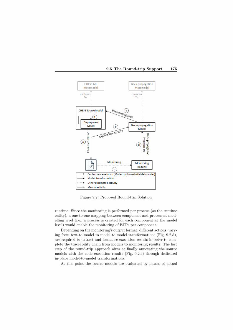
9.5 The Round-trip Support 175
Figure 9.2: Proposed Round-trip Solution
runtime. Since the monitoring is performed per process (as the runtimeentity), a one-to-one mapping between component and process at mod-elling level (i.e., a process is created for each component at the modellevel) would enable the monitoring of EFPs per component.
Depending on the monitoring’s output format, different actions, vary-ing from text-to-model to model-to-model transformations (Fig. 9.2.d),are required to extract and formalise execution results in order to com-plete the traceability chain from models to monitoring results. The laststep of the round-trip approach aims at finally annotating the sourcemodels with the code execution results (Fig. 9.2.e) through dedicatedin-place model-to-model transformations.
At this point the source models are evaluated by means of actual

176 Paper D
EFPs’ values and, if needed, the allocation of components to processescan be tuned (Fig. 9.2.f) by the developer to generate more resource-efficient code. Thanks to the automated support, the process can bere-iterated until the developer is satisfied with the generated code.
9.6 From Models to Code and BackIn this section we show the application of the round-trip support to theAAL2 subsystem in terms of generation of C++ code from the sourcemodel described in Section 9.4, monitoring of the code execution onOSE and back-propagation of gathered values to the CHESS model.Moreover, after performing deployment tuning based on such values, were-iterate the process to show how these modifications at modelling levelcan affect EFPs of re-generated code.
9.6.1 Generation of C++ from CHESS ModelA set of model-to-model transformations operates on the CHESS modelto generate three different intermediate artefacts: i) Instance model, thatstores component instances and links among them via ports [31], ii) In-termediate model, that represents the main intermediate artefact in theprocess and contains all the information needed to generate code [5],and iii) Back-propagation model, that contains explicit traceability linksbetween model elements and code as well as place-holders for EFPs val-ues coming from the following monitoring activities [5]. The intermediatemodel is enriched with behavioural information defined in ALF by meansof parsing operations and in-place model-to-model transformations. Atthis point, the C++ implementation code is generated through model-to-text transformations taking as input the intermediate model [5].
Each of these intermediate artefacts conforms to its correspondingmetamodel that we expressly defined for the code generation process.With regards to the technologies employed in the generation process,model-to-model transformations are defined by means of OperationalQVT, while model-to-text transformations are defined in Xpand [32].
As aforementioned, the synthesis described in [5] was limited tosingle-process applications, which prevented its employment for deploy-ment issues. The approach has been therefore enhanced in order to beable to consider deployment configurations specified at modelling level

9.6 From Models to Code and Back 177
Figure 9.3: Multiprocess Deployment Configuration of AAL2 Subsystem
and therefore generate single- or multi-process implementation accord-ingly. Deployment is described in CHESS-ML by means of an ad-hocmodel in which the modeller defines allocation of components instancesto processes with the help of specific concepts provided by MARTE.In Figure 9.3 a portion of the deployment model concerning the AAL2subsystem is depicted.
More specifically the following possible allocations are shown:• Different instances of a same component on different processes:represented by the two instances of the component NCIClient_i(SwSystem_NCIClient_inst) respectively allocated to processAand processB (Figure 9.3.a);
• Single component instance on a process: represented by the in-stance of AAL2RIClient_i (SwSystem_AAL2RIClient_inst) allo-cated to processC (Figure 9.3.b);
• Multiple set of component instances on a single process: repre-sented by the entire set of NetConn_i (SwSystem_NetConn_inst)

178 Paper D
instances allocated to processE (Figure 9.3.c).In order to achieve this, the transformation process proposed has beenenhanced to take into account the information carried by the deploy-ment model that, together with the functional model, drives the codegeneration. More specifically, in the case of code tailored for OSE, thatinformation is exploited to create processes and deploy component in-stances on them, as well as generate the communication code in orderto distinguish between:• Intraprocess communication: communication between compo-
nents deployed on a same process is achieved by function calls;• Interprocess communication: components allocated to differ-
ent processes communicate via signals across processes.More specifically, the communication between components defined in
the CHESS-ML model in terms of ALF as function calls on ports had tobe properly translated into appropriate intermediate concepts. Depend-ing on the deployment configuration of the communicating components,a function call in the model is translated into (i) a function call, if thecomponents are deployed on the same process, or (ii) into a messagesend (i.e, OSE signal) in the case of components deployed on differentprocesses. This means that the entailment of different deployment con-figurations has introduced a higher degree of variability in the semanticinterpretation of the design models that depends on the modelled deploy-ment. The ability to correctly interpret such information and therebygenerate code that reflects the modelled deployment configuration hasbeen embedded in the model transformations responsible for the codegeneration.
Due to the complexity of the multi-process code generation, the de-tails related to the involved artefacts ranging from intermediate meta-models to model transformations will be dealt with separately. For theinterested reader, preliminary information about the single-process gen-eration chain can be found in [5].
9.6.2 Monitoring Code ExecutionIn order to enable the needed monitoring features, specific extensionsto the execution platform have been made. These extensions have beenimplemented mainly in the form of two additional system processes: onefor monitoring and another for logging. These two processes are assignedlower priorities than the generated application ones. The monitoring pro-

9.6 From Models to Code and Back 179
cess is responsible for calculating and determining the values for EFPsof interest for both the whole system (e.g., overall CPU usage) as wellas per process. The actual task of logging such information is separatedfrom the monitoring process and performed by the logging one. Thisseparation allows to mitigate the side effects of resource-demanding I/Oactivities. When a request for monitoring is issued by one of the applica-tion processes, the monitoring process starts executing and determiningEFPs’ values. The information to be logged is sent to the logging processby the monitoring one through apposite signals. Therefore, if the loggingprocess does not get the needed CPU time to perform its job, the signalssent to it are pushed in its signal queue, maintained automatically byOSE, and processed as soon as it gets to execute.
The implemented monitoring process is capable of determining valuesfor the following properties:• System-level properties: total CPU load, total number of gener-ated signals in the system, system throughput (sent and receivedpackets), total number of processes in the system;
• Process-level properties: total execution time of a process (fromthe startup of the system including all invocations of it), instanceexecution time of a process (one invocation and instance), responsetime of a process, heap and stack usage for a process, number ofsignals generated by a process, and CPU load of a process.
To calculate execution and response times, swap_in and swap_outhandlers of OSE have been used. The former event handler is invokedeach time a process gets CPU to execute, and the latter is invoked whenCPU is taken from a process and it is preempted. The algorithms andmechanisms for the calculation of execution and response times havebeen implemented into these two event handlers. However, since theyare invoked for every process in the system, additional tweaks were madein order to filter their executions for only the generated application pro-cesses which are of interest.
The monitoring activities give a textual description of the gatheredvalues as output. The results of monitoring the execution of the C++code generated from the AAL2 model and with the deployment con-figuration partially depicted in Fig. 9.3 are shown partially in Listing9.1.
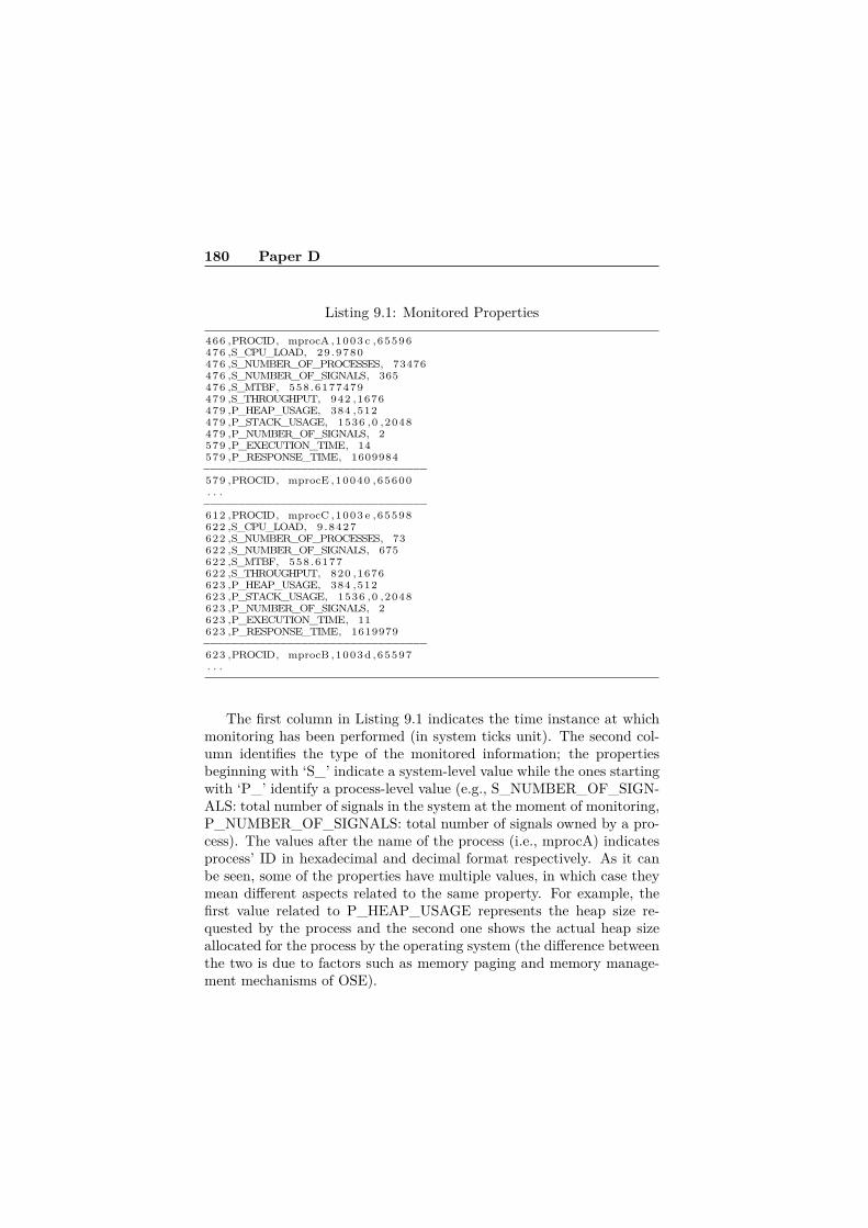
180 Paper D
Listing 9.1: Monitored Properties
466 ,PROCID, mprocA ,1003 c ,65596476 ,S_CPU_LOAD, 29.9780476 ,S_NUMBER_OF_PROCESSES, 73476476 ,S_NUMBER_OF_SIGNALS, 365476 ,S_MTBF, 558.6177479479 ,S_THROUGHPUT, 942 ,1676479 ,P_HEAP_USAGE, 384 ,512479 ,P_STACK_USAGE, 1536 ,0 ,2048479 ,P_NUMBER_OF_SIGNALS, 2579 ,P_EXECUTION_TIME, 14579 ,P_RESPONSE_TIME, 1609984−−−−−−−−−−−−−−−−−−−−−−−−−−−−−−−−579 ,PROCID, mprocE ,10040 ,65600. . .−−−−−−−−−−−−−−−−−−−−−−−−−−−−−−−−612 ,PROCID, mprocC ,1003 e ,65598622 ,S_CPU_LOAD, 9.8427622 ,S_NUMBER_OF_PROCESSES, 73622 ,S_NUMBER_OF_SIGNALS, 675622 ,S_MTBF, 558.6177622 ,S_THROUGHPUT, 820 ,1676623 ,P_HEAP_USAGE, 384 ,512623 ,P_STACK_USAGE, 1536 ,0 ,2048623 ,P_NUMBER_OF_SIGNALS, 2623 ,P_EXECUTION_TIME, 11623 ,P_RESPONSE_TIME, 1619979−−−−−−−−−−−−−−−−−−−−−−−−−−−−−−−−623 ,PROCID, mprocB ,1003 d ,65597. . .
The first column in Listing 9.1 indicates the time instance at whichmonitoring has been performed (in system ticks unit). The second col-umn identifies the type of the monitored information; the propertiesbeginning with ‘S_’ indicate a system-level value while the ones startingwith ‘P_’ identify a process-level value (e.g., S_NUMBER_OF_SIGN-ALS: total number of signals in the system at the moment of monitoring,P_NUMBER_OF_SIGNALS: total number of signals owned by a pro-cess). The values after the name of the process (i.e., mprocA) indicatesprocess’ ID in hexadecimal and decimal format respectively. As it canbe seen, some of the properties have multiple values, in which case theymean different aspects related to the same property. For example, thefirst value related to P_HEAP_USAGE represents the heap size re-quested by the process and the second one shows the actual heap sizeallocated for the process by the operating system (the difference betweenthe two is due to factors such as memory paging and memory manage-ment mechanisms of OSE).

9.6 From Models to Code and Back 181
9.6.3 Back-propagation to CHESS ModelWhile a similar approach had been proposed in [5], since the monitoringfeatures, and thereby the output format, had entirely changed, the back-propagation facilities had to be consequently adapted. More specifically,a specific in-place text-to-model transformation has been implementedfrom scratch in order for the monitoring results of interest to be ma-nipulated and stored in the back-propagation model. Observed valuesas source for the back-propagating transformations are not enough. Infact, the traceability chain defined along the path from design modelsto observed values is also part of the source artefacts to be fed to thetransformations in order to correctly propagate values back to the designmodels. The actual enrichment of the CHESS model with such EFPsvalues is performed through a model-to-model transformation. Takingas input the CHESS model and the back-propagation model, it performsa set of in-place transformations (adapted version of the ones proposedin [5]) on the CHESS model to enrich it with the observed values storedin the back-propagation model. The results of the back-propagation arepartially shown by means of extra-functional decorations of the AAL2model in Fig. 9.4. More specifically, we can notice that values concerningmprocA are back-propagated to instance 1 of NCI_Client_i (marked by[1] – e.g., EXECUTION_TIME[1]) while the ones carried by mprocC ap-ply to the single instance of AAL2RI_Client_i. Such correspondence isstored in the back-propagation model and originates from the deploy-ment model depicted in Fig. 9.3. Regarding the technologies used inthe back-propagation process, model-to-model transformations are de-fined by means of Operational QVT as well as text-to-model transfor-mations (which are aided by structured text parsers defined in Java).Once the monitored results have been back-propagated, the developerhas at her disposal the modelled system enriched with actual valuesgathered at runtime. The values depicted in Listing 9.1 and propagatedback to the AAL2 model (in Fig. 9.4) are related to the deploymentconfiguration in which the component instance NCI_Client_i[1] is de-ployed on ProcessA (mprocA in Listing 9.1) and the component instanceAAL2RI_Client_i[1] is allocated to ProcessC (mprocC).
9.6.4 Evaluation of Deployment ConfigurationsAt this point, let us try out a different deployment configuration inwhich we allocate both NCI_Client_i[1] and AAL2RI_Client_i[1] to

182 Paper D
Figure 9.4: Decorated AAL2 model in CHESS
ProcessA, since the communication between them is quite dense. Oncethe model is modified, the code can be regenerated and its executionmonitored. In Table 9.1 the monitoring results concerning both the firstas well as the tuned deployment configurations are depicted. Configu-ration 1 represents the deployment of the two component instances onseparate processes, while 2 concerns the deployment of both instanceson a single process.
As we can see, by changing the deployment configuration, in the spe-cific case by allocating the two instances on the same process, we actu-ally experience a decrease of the execution time of AAL2RI_Client_ifrom 11 to 3. Besides this reduction which may not be relevant inthe actual employment of the system, what we aimed at pointing outwas the usefulness of having an automatic mechanism for gathering andback-propagating runtime values to model level for allowing thoroughevaluation of the system’s deployment configuration. While providingmeaningful values at model level, the approach is not yet able to provideany hint on how to interpret them. Limitations of the current solutionin this sense as well a future enhancements towards further automationin the tuning phase are discussed in the next section.

9.7 Discussion and Future Work 183
Config. Comp. Instance Process Exec. Time1 NCI_Client_i[1] A 141 AAL2RI_Client_i C 112 NCI_Client_i[1] A 142 AAL2RI_Client_i A 3
Table 9.1: Different deployments that induce different monitoring results
9.7 Discussion and Future Work
Validating the approach against an industrial case-study gave us thepossibility to evaluate the scalability of the proposed solution by testingseveral design model sizes for the same system. The hardware configu-ration was composed by a Windows machine running on a 2.6GHz CPUand 8GB RAM. Moreover, we employed the OSE Soft-Kernel (SFK)5.5.1 as target platform for code execution. The SFK edition providesa simulated environment of the actual target embedded board on a hostmachine (a Windows or Linux host) and accurately reproduces the be-haviour of the real environment. Focusing on the most time-consumingtask in the approach (i.e., automatic code generation) and consideringn as the greatest number of instances per component, m as the greatestnumber of instances per port, and k as the number of hierarchical compo-sition level, the general limit behaviour of the computation is representedby O((n ∗m)k). Overall the proposed solution, on a model with k = 2,resulted very scalable up to n + m = 103 (i.e., within 5 minutes) whilegradually slowing down for greater number of instances (e.g., over 30minutes for n+m = 104). More specifically, in terms of number of com-ponent and port instances (i), the generation time (in seconds) was: (i)52s for i = 90, 113s for i = 1853, and 831s for i = 16003 (complete AAL2subsystem). However, the presented validation has been performed on apreliminary implementation of the code generator which focuses mostlyon the correctness of the generation process with no major emphasis onperformance issues. That is why we expect to achieve better results, interms of scalability, with a more mature version of the code generator.
Regarding the time needed for monitoring activities, it heavily de-pends on the duration of the code execution since the measurementsthemselves are mostly performed by parallel processes during the exe-cution. Nevertheless, the calculation of more complex EFPs could in-troduce additional complexity hence requiring additional computation

184 Paper D
time.Concerning back-propagation tasks, they resulted to be more scalable
thanks to the detailed information, concerning the path to the specificmodel element to be annotated, carried by the back-propagation model.This means that most of the needed computation is performed whengenerating the back-propagation model, while the actual values injection,first from monitoring results to back-propagation model and thereforefrom the latter to the design model only involves an update of specificvalues with no need of complex searches nor navigations.
Generally, the number of iterations for reaching the desired EFPsdepends on the accuracy of measurements as well as the modeller’s abil-ity in both modelling the system and also effectively employ the back-propagated values to tune the models accordingly. That is to say thatthe developer is supposed to be able to understand the back-propagatedvalues in relation to the expected behaviour and thereby tune the modelsaccordingly to generate a better-performing implementation. In aid tothe modeller, model-based analysis and deployment optimization tech-niques could be exploited to minimise the number of iterations.
As described in the previous sections, measurements of EFPs are gen-erally performed at process level, which means that in order to obtaincomponent-level values, each component should be deployed on a sepa-rate process. This, although representing an important step forward incomparison to the previous version of our approach, only opens up tofurther enhancements. In fact, while in principle the back propagationcan handle the case of several components mapped to one process, themonitoring facilities cannot due to the execution platform. Therefore,future improvements will entail the possibility to always monitor prop-erties at runtime per component even when several components wouldbe deployed on a same process. In order to achieve this, both improveddedicated marking in the generated code as well as specific tweaks atplatform level should be defined and implemented.
We plan to further enhance the code generation in order to addressdeployment on multiple processing units, which would amplify the ben-efits of multiprocessing addressed in this work (i.e., multi-process onsingle processing unit).
As aforementioned, starting from an initial model, the approach isiterated at will until the EFPs requirements are fulfilled. Therefore, onceproviding support for multicore solutions, there would be the possibil-ity to minimise the number of such iterations by exploiting model-based

9.8 Conclusion 185
deployment optimization techniques (e.g., [33] by Feljan et al.) to en-hance the deployment-tuning phase with a semi-automated approachthat combines both runtime measurements as well as design-time per-formance predictions.
Additionally, as for the monitoring part, by adding the support forfurther EFPs, it becomes possible to take into consideration more param-eters for tuning the deployment of the system. It would be possible, asan extension of the monitoring part, to enable the calculation of MTBFfor each generated process, and therefore for the components that aremapped to it. Having MTBF values as one of the parameters indicatingthe dependability of the system, would add a further dimension (i.e.,dependability) at model level that may help in making deployment deci-sions. Similarly, if there would be a mechanism to determine an indicatorvalue for the energy consumption of each process (e.g., something similarto the ACPI standard [34]) it would become possible to even tune thesystem in terms of energy consumption. The feasibility of this possibleenhancement needs further investigations.
9.8 ConclusionIn this paper we described a possible solution to relieve the developer’s ef-fort in optimising deployment configuration when developing component-based embedded systems with the help of accurate measurements gath-ered at system implementation level and avoiding manual editing of code.The solution consists of a fully automated model-driven round-trip ap-proach that enables: (i) generation of full-fledged code from source mod-els entailing customisable single- and multi-process deployment configu-rations, (ii) monitoring of code execution for measuring a selected set ofEFPs at system implementation level, and (iii) back-propagation facili-ties to enrich the source models with such measurements.
By operating exclusively at modelling level, the developer is dis-charged from inspecting as well as editing generated code. At the sametime, through automatic back-propagation of measurements gathered atsystem implementation level, the approach assists the developer in un-derstanding at first sight the relationships between expected and actualbehaviour hence enabling a well-aware tuning of deployment configura-tion at model level.
While a previous version of the round-trip support (i.e., only single-

186 Paper D
process deployment was entailed) had been already described in [5], inthis work we describe how we enhanced it to enable synthesis of designmodels to generate either highly resource efficient (in terms of inter-system communications) single-process applications or exploit multi-process configurations that could run in parallel on multicores. More-over, having at our disposal this variety of deployment options, we wereable to focus on how the round-trip support can employ measurementsat system implementation level towards deployment optimization andwe showed it by applying the solution to an industrial example in thetelecom-domain. Additionally, we described complexity and scalabilityof the different steps constituting the solution, as well as interestingdirections for possible future enhancements.
9.9 AcknowledgmentsThis research is supported by the RALF3 (Swedish Foundation for Strate-gic Research (SSF), http://www.mrtc.mdh.se/projects/ralf3/) projectand the Swedish Knowledge Foundation (KKS) through the ITS-EASYresearch school.

Bibliography
[1] J. Bezivin. On the unification power of models. Software and Sys-tems Modeling, pages 171–188, 2005.
[2] Ivica Crnkovic. Component-based software engineering for embed-ded systems. In Procs of ICSE’05, pages 712–713. ACM.
[3] R. Land, J. Carlson, S. Larsson, and I. Crnkovic. Project Monitoringand Control in Model-driven and Component-based Developmentof Embedded Systems - The CARMA Principle and PreliminaryResults. In Procs of ENASE’10, pages 253–258.
[4] N. Siegmund, M. Rosenmuller, M. Kuhlemann, C. Kastner, andG. Saake. Measuring Non-Functional Properties in Software Prod-uct Line for Product Derivation. In Procs of APSEC’08, pages 187–194, 2008.
[5] F. Ciccozzi, A. Cicchetti, and M. Sjödin. Round-trip support forextra-functional property management in model-driven engineeringof embedded systems. Information and Software Technology, 2012.
[6] M. Saadatmand, M. Sjödin, and N. U. Mustafa. Monitoring Ca-pabilities of Schedulers in Model-Driven Development of Real-TimeSystems. In Procs of ETFA 2012, 2012.
[7] K. Czarnecki and S. Helsen. Feature-based survey of model trans-formation approaches. IBM Systems Journal, pages 621–645, 2006.
[8] S. Kent. Model Driven Engineering. In IFM, 2002.
[9] Object Management Group (OMG). UML Superstructure Specifica-tion V2.3. http://www.omg.org/spec/UML/2.3/Superstructure/PDF/, 2011. [Online. Last access: 11/04/2012].
187

188 Bibliography
[10] N. Delgado, A.Q. Gates, and S. Roach. A taxonomy and catalogof runtime software-fault monitoring tools. Software Engineering,IEEE Transactions on, 30(12):859 – 872, 2004.
[11] A. Cicchetti, F. Ciccozzi, S. Mazzini, S. Puri, M. Panunzio, A. Zovi,and T. Vardanega. CHESS: a model-driven engineering tool envi-ronment for aiding the development of complex industrial systems.In Procs of ASE’12, pages 362–365. ACM.
[12] OMG. Action Language For FoundationalUML - ALF. http://www.omg.org/spec/ALF/, Oct 2010.
[13] Enea. http://www.enea.com, Last Accessed: January 2013.
[14] Enea. The Architectural Advantages of Enea OSE in Telecom Appli-cations. http://www.enea.com/software/solutions/rtos/, LastAccessed: January 2013.
[15] Z. Navabi, S. Day, and M. Massoumi. Investigating Back Annota-tion of Timing Information into Dataflow descriptions. In Procs ofVHDL International User Forum, pages 185–195, 1992.
[16] G. Mahadevan and J. R. Armstrong. Automatic Back Annotationof Timing into VHDL Behavioral Models. In Procs of VHDL Inter-national User Forum, pages 27–41, 1995.
[17] Á. Hegedüs, G. Bergmann, I. Ráth, and D. Varró. Back-annotationof Simulation Traces with Change-Driven Model Transformations.In Procs of SEFM’10, pages 145–155, 2010.
[18] E. Guerra, D. Sanz, P. Díaz, and I. Aedo. A transformation-drivenapproach to the verification of security policies in web designs. InProcs of ICWE’07, pages 269–284, Berlin, Heidelberg. Springer-Verlag.
[19] H. Koziolek. Performance evaluation of component-based softwaresystems: A survey. Performance Evaluation, 67(8):634–658, 2010.
[20] S. Yacoub. Performance Analysis of Component-Based Applica-tions. In Software Product Lines, LNCS, pages 299–315. SpringerBerlin Heidelberg, 2002.

Bibliography 189
[21] A. Mos and J. Murphy. A framework for performance monitor-ing, modelling and prediction of component oriented distributedsystems. In Procs of WOSP’02, pages 235–236. ACM.
[22] A. Diaconescu and J. Murphy. Automating the performance man-agement of component-based enterprise systems through the use ofredundancy. In Procs of ASE’05, pages 44–53. ACM.
[23] T. Parsons and J. Murphy. Detecting Performance Antipatterns inComponent Based Enterprise Systems. Journal of Object Technol-ogy, pages 55–91, 2008.
[24] A. Wall, J. Kraft, J. Neander, C. Norström, and M. Lembke. In-troducing Temporal Analyzability Late in the Lifecycle of ComplexReal-Time Systems. In Procs of RTCSA’03. Springer Berlin Hei-delberg.
[25] S.E. Chodrow, F. Jahanian, and M. Donner. Run-time monitoringof real-time systems. In Procs of RTSS’91, pages 74 –83.
[26] M. Saadatmand, A. Cicchetti, and M. Sjödin. Design of adaptivesecurity mechanisms for real-time embedded systems. In Procs ofESSoS’12, pages 121–134. Springer-Verlag, 2012.
[27] J. Huselius and J. Andersson. Model Synthesis for Real-Time Sys-tems. In Procs of CSMR’05, pages 52–60. IEEE Computer Society.
[28] M. Saadatmand, A. Cicchetti, and M. Sjödin. UML-Based Modelingof Non-Functional Requirements in Telecommunication Systems. InProcs of ICSEA’11.
[29] M. Saadatmand, A. Cicchetti, and M. Sjödin. Toward Model-BasedTrade-off Analysis of Non-Functional Requirements. In Procs ofSEAA’12.
[30] B. Grammel and S. Kastenholz. A generic traceability frameworkfor facet-based traceability data extraction in model-driven softwaredevelopment. In Procs of ECMFA-TW’10. ACM.
[31] F. Ciccozzi, A. Cicchetti, and M. Sjödin. Exploiting UML SemanticVariation Points to Generate Explicit Component Interconnectionsin Complex Systems. In Procs of ITNG’13). IEEE CS.
[32] Eclipse Projects. Xpand. http://www.eclipse.org/modeling/m2t/?project=xpand, October 2011.
[33] J. Feljan, J. Carlson, and T. Seceleanu. Towards a model-basedapproach for allocating tasks to multicore processors. In Procs ofSEAA’12.
[34] ACPI: Advanced Configuration & Power Interface. http://www.acpi.info/, Last Accessed: January 2013.

Chapter 10
Paper E:Towards AccurateMonitoring ofExtra-FunctionalProperties in Real-TimeEmbedded Systems
Mehrdad Saadatmand, Mikael SjödinThe 19th Asia-Pacific Software Engineering Conference (APSEC), HongKong, December, 2012.
191
Abstract
Management and preservation of Extra-Functional Properties (EFPs) iscritical in real-time embedded systems to ensure their correct behavior.Deviation of these properties, such as timing and memory usage, fromtheir acceptable and valid values can impair the functionality of thesystem. In this regard, monitoring is an important means to investigatethe state of the system and identify such violations. The monitoringresult can also be used to make adaptation and re-configuration decisionsin the system as well. Most of the works related to monitoring EFPs arebased on the assumption that monitoring results accurately representthe true state of the system at the monitoring request time point. Insome systems this assumption can be safe and valid. However, if in asystem the value of an EFP changes frequently, the result of monitoringmay not accurately represent the state of the system at the time pointwhen the monitoring request has been issued. The consequences of suchinaccuracies can be critical in certain systems and applications. In thispaper, we mainly introduce and discuss this practical problem and alsoprovide a solution to improve the monitoring accuracy of EFPs.

10.1 Introduction 193
10.1 IntroductionSuccessful design of real-time embedded systems depends heavily on howthey behave with respect to their extra-functional properties. This ismainly due to the constraints and limitations of these systems in termsof available resources [1]. Therefore, a real-time embedded system needsto achieve its functionality under these limitations and constraints. Thisimplies that the extra-functional properties of the system should remainwithin an acceptable range and violations in this aspect should be man-aged and prevented. For example, due to memory constraints, differentcomponents of a system should not consume more memory than ex-pected. Similarly, in terms of timing properties, a task may not executemore than its allowed execution time budgets; otherwise, it can affectthe overall behavior and functionality of the system.
Monitoring extra-functional properties is an important means in thisregard not only to detect and identify violations but also to provide nec-essary information for runtime adaptation and reconfiguration in systems[2, 3]. However, accuracy of the monitored values plays a significant rolein the correct identification of violations and also making appropriatedecisions for performing runtime adaptation. The term accuracy in thispaper is used in the sense that to what extent a monitored value rep-resents the actual state of the system and the extra-functional propertythat is monitored at a certain time point.
One of the factors that contribute to the accuracy of monitored extra-functional properties is the time difference between the point when a re-quest for monitoring an extra-functional property is issued and the timepoint when it is actually monitored and its value is obtained. This timedifference (referred to as ‘monitoring time difference’ in this paper) isespecially critical in systems where frequent changes of extra-functionalproperties can happen. An example could be when CPU load in a systemchanges constantly due to frequent termination and execution of differentjobs or when memory usage varies rapidly because of frequent allocationand deallocation of memory. For this reason, it is also deemed necessaryto consider timestamps in monitoring of extra-functional properties to beable to judge their accuracy and validity. A point to remember thoughis that how this time difference affects the accuracy of monitored valuescan change from one system and even execution scenario to another.For example, in one system, rapid changes in CPU load may happenwhile memory usage can remain at a certain level. In such a system, the

194 Paper E
aforementioned monitoring time difference is critical for validity and ac-curacy of CPU load measurements while it may not be so for monitoringmemory usage. In another system the situation could be the opposite ofthis case.
In this paper, we focus on this problem and how we can improve theaccuracy of monitored values by having more control over the time differ-ence between a request for monitoring and the actual act of monitoring.We introduce an approach which enables to reduce this time differenceand thus helps with the accuracy of the monitored extra-functional prop-erties. This is achieved by considering priorities for performing moni-toring of different extra-functional properties. The approach works byperforming the task of monitoring properties with higher frequency ofchanges (for which the monitoring time difference can greatly affect theaccuracy of the obtained values) at a higher priority level than otherproperties. We have implemented the approach using OSE Real-TimeOperating System (RTOS) [4] which is a commercial RTOS used heav-ily in telecommunication systems and is embedded in millions of devicesaround the world.
The remainder of the paper is structured as follows. In Section 10.2 ashort introduction to OSE RTOS is provided. Section 10.3 describes thegeneral approach along with its implementation and in Section 10.4, anevaluation of the implemented approach is done. Discussions on severalimportant points regarding the suggested approach is done in 10.5. InSection 10.6 related works are mentioned and finally in Section 10.7conclusions are made and future directions are explained.
10.2 OSE Real-Time Operating SystemOSE is a real-time operating system developed by Enea [4] designed fromthe ground for use in fault-tolerant distributed systems that are com-monly found in telecommunication domain, ranging from mobile phonesto radio base stations [4]. It provides preemptive priority-based schedul-ing of tasks. OSE offers the concept of direct and asynchronous mes-sage passing for communication and synchronization between tasks, andOSE’s natural programming model is based on this concept. The Inter-process Communication Protocol (IPC) in OSE, allows tasks to run ondifferent processors or cores, utilizing the same message-based communi-cation model as on a single processor. This programing model provides
10.3 Priority-Based Monitoring Approach 195
the advantage of not needing to use shared memory among tasks. Therunnable real-time entity equivalent to a task is called process in OSE,and the messages that are passed between processes are referred to assignals (thus, the terms process and task in this paper can be consideredinterchangeably). Processes can be created statically at system start-up,or dynamically at runtime. Static processes last for the whole life timeof the system and cannot be terminated. Types of processes that canbe created in OSE are: interrupt process, timer interrupt process, pri-oritized process, background process, and phantom process. A processcan be in one of the following states: ready, running or waiting. Oneinteresting feature of OSE is that the same programming model basedon signal passing can be used regardless of the type of a process. OSEalso has a tool for debugging, profiling and monitoring called Optima.Among many other features, Optima enables to monitor properties suchas CPU load and number of signals by communicating with a targetembedded system using OSE signals.
10.3 Priority-Based Monitoring Approach10.3.1 Background ScenarioTo monitor different properties in the system, a monitoring process hasbeen implemented. In this process, by using the APIs provided by theoperating system, values for different properties such as total CPU load,CPU load of a specific process, memory usage (both heap and stack us-age), total number of generated signals in the system, number of signalsbelonging to a certain process, etc. can be monitored. When an applica-tion (e.g., a monitoring and profiling tool) needs to obtain the value forany of the properties, it just sends a signal containing a code identifyingthe desired property to the monitor process. Upon the receipt of thissignal, the monitor process which is in waiting state, starts and obtainsthe property value and sends it back to the requesting process. In thisscenario, the monitor process needs to compete with other processes inthe system based on their assigned priority levels to obtain CPU andperform its job. Therefore, it is natural that there will be some timedifference until the monitor process can successfully obtain the value ofa property. This scenario is shown in Figure 10.1. We aim to reduce thetime difference which is denoted in the figure by t for properties whosevalues can change during this time and also this change is considered

196 Paper E
important and sensitive.
Figure 10.1: Monitoring a property and the time difference between therequest for monitoring and the reply
As stated before, if a property in the system changes so frequentlythen this time difference affects the accuracy of its read value. In thiscase, if the application requesting this value needs to perform some cal-culations and make decisions based on the value of the property at theexact time point that it issued the request for monitoring, the accuracyof the monitored value can affect the correctness of such calculations anddecisions.
10.3.2 Priorities for Extra-Functional Properties
As described so far, the frequency of change in the value of properties inthe system can be different from one property to another. Consideringthis fact, the user may prefer to fetch the value of a specific propertywith a shorter monitoring time difference to have better accuracy forit. To capture this need, we let different priority levels be assigned fordifferent properties for performing monitoring. This way, the monitoringof CPU load, for example, can be done at a higher priority level thanthe monitoring of memory usage. It is achieved by dynamically adjust-ing the priority of the monitoring process for each property, instead ofalways invoking the monitoring process at the same fixed priority level.Therefore, the system becomes more flexible and monitoring of differentproperties does not have to be done at the fixed and default priority levelof the monitoring process.

10.4 Evaluation 197
10.3.3 ImplementationThe preferred way of communication between processes in OSE is throughsignals. Send and Receive APIs are provided in OSE for this purpose.To send a signal, a pointer to the signal structure along with the PIDof the receiver is specified as: send(&sig, pid). In our implementation,the signal contains an identifier code to tell the monitor process whichpriority to monitor, which is defined in the system in the form of anenum structure in C/C++.
To allow the specification of priority levels for properties, we havedefined a wrapper around the send API as: send_w_prio(&sig, pid,prio). What send_w_prio does is basically that it first sets the priorityof the monitor process (which is in the waiting mode to receive a signal)to the value of prio, and then sends to it the rest of the parameters usingthe normal send API. This way, it can be triggered to execute at a loweror higher priority level than its default value.
10.4 EvaluationTo test the suggested approach, a simulation environment has beensetup. A monitor process is implemented which waits to receive a signalcontaining the identifier of a property based on which it then obtainsthe value for that property from the system and sends back the resultto the requester. Another process (referred to as P) is also implementedwhich constantly changes the value of a dummy property (representedby a variable called N ) to a random number and logs it in a file for laterinspections and comparisons. The purpose of this process is to simulatea property whose value changes very frequently and constantly in thesystem. Two additional processes are defined in the system with prioritylevels below that of process P but above the default priority of monitorprocess (we call them I1 and I2). A shell command (in the OSE shell)called App has also been created which when executed sends a requestfor monitoring the property N to the monitor process.
When a request for monitoring the property N is initiated using theadded shell command, the execution of the monitor process is delayedby higher priority processes. This situation is demonstrated in the Table10.1 where log records corresponding to such cases (extracted from thelog files generated by the P and monitor processes) are listed.
The first row in the table, for example, shows that the request for

198 Paper E
MRTP* Monitoring Done at Monitored Value Value at MRTP*(µs) (µs)
5140013 5150001 838 32006630025 6630026 5600 56007350011 7360001 5883 9600
13460011 13470001 5032 1600
Table 10.1: Discrepancy between property values at monitoring requesttime and when actual monitoring is done.(* MRTP:Monitoring Request Time Point - from the startup of the system)
monitoring property N is issued at 5140013µs (from the start of thesystem). Due to the interferences from the two other processes (I1 andI2) in the system, the actual monitoring is performed at time point5150013µs which results in obtaining 838 as the value for the property(remember that when P executes, it repeatedly generates a random num-ber and sets it as the value of N ). However, by consulting the generatedlog file from process P, we can see that the actual value of the propertyat the time when monitoring request has been issued was 3200.
In the next step, we initiate again a request for monitoring but thistime with a priority higher than those of I1 and I2 processes. Part of theresult from the generated log files is shown in Table 10.2.
MRTP* Monitoring Done at Monitored Value Value at MRTP*(µs) (µs)
5970013 5970014 6804 68048630001 8630002 6698 6698
12060001 12060002 3629 362914500018 14520000 7673 960021590011 21590012 6400 6400
Table 10.2: Property values using flexible priority levels for the monitorprocess.(* MRTP:Monitoring Request Time Point - from the startup of the system)
From the result of the second case, we can see that more instancesof monitoring have managed to obtain accurate results for the property.The discrepancies which are still observed in this scenario, such as thesecond row from the bottom of Table 10.2, are due to the re-activationsof process P which still has higher priority than the monitor process (the1µs difference between the monitoring request time point and actual timeof performing monitoring is the natural increment of internal clock of thesystem).

10.5 Discussions 199
10.5 DiscussionsIn the previous section, it was shown how by allowing to assign prior-ity levels for monitoring of different properties it becomes possible toachieve better accuracy. However, there are some important points thatneed careful attention. If the priority of the monitor process is increased,it also means that other processes in the system can suffer delays dueto preemption by the now higher priority monitor process. The con-sequences of such delays are of course dependent on the nature andresponsibilities of those processes in the system. Therefore, the user ini-tiating a monitoring request at a high priority level should also considerits consequences.
Another factor that contributes to the monitoring time difference andthus accuracy of monitored properties is the time length of the monitor-ing process itself. Implementation efficiency of the monitor process canthus help with the reduction of monitoring time difference.
A point which can be specific to our implementation is that the shelldaemon in OSE is a system process which also has an assigned prioritylevel. This can be important for knowing how the shell command that weimplemented is interpreted by the shell daemon and executed and howthe daemon behaves in terms of getting CPU time to execute comparingits priority level to other processes in the system. In our settings, sincethe priority of the shell daemon was the same default value in both cases,its effect on monitoring was simply ignored.
Here we mainly discussed the frequency of change in the value of aproperty. Another aspect that can also be added to the picture is themagnitude of such changes and its importance for accurate monitoring.For example, the value of a property can change quite frequently in smallincrements from 1.0 to 5.0. But depending on the use of the monitoredvalue, the difference between 1.45 and 1.80 may not be significant at all.Therefore, deciding for which properties we need more accurate moni-toring is dependent on the use of the monitored values as well as theimportance, tolerance and negligible fluctuations in the value of thoseproperties. Moreover, in this paper we did not discuss how exactly thevalues of different extra-functional properties are calculated and deter-mined. For some properties such as CPU load or the number of signals(in case of OSE and signal-based systems) it may be straightforward toobtain such values, while for some other properties such as reliability, itmight be very cumbersome and complicated. This topic, however, is out

200 Paper E
of the scope of the paper.
10.6 Related Work
The work done in [5] discusses the issue of accuracy in monitoring per-formance of a system using the hardware counters and registers that areavailable on modern microprocessors. One of the differences betweenthis work and ours is that it compares the accuracy of monitoring usinghardware counters versus hardware sampling while we basically discussedthe issue of accuracy by targeting the monitoring time difference. It alsotouches on the effects of adding monitoring features by acknowledgingthe fact that “as in any physical system, the act of measuring perturbsthe phenomenon being measured” [5]. [6] which introduces a very inter-esting approach to reduce energy consumption in real-time distributedembedded systems, defines the concept of monitoring intervals for cycli-cally monitoring the system to identify and exploit dynamic slacks. Itdiscusses the overhead of monitoring and how to find an optimal intervalvalue for it. However, it does not deal with the accuracy of monitoringresults versus constant changes in the state of the system.
As for the application of monitoring, [7] serves an example for theuse of monitoring results where models of real-time systems are synthe-sized based on the monitoring information that is collected. In [3], wehave introduced and implemented an adaptive approach using monitor-ing information about timing behaviors of encryption algorithms to bal-ance security and timing requirements in real-time systems. Regardingthe implementation of monitoring mechanisms, in [2], we have discussedthe challenges and practicalities of monitoring timing properties in real-time systems, especially in industrial RTOSes, and provided a solutionto improve monitoring of real-time events. The work in [8] providesa framework for monitoring of timing properties and a model for thespecification of timing constraints. It provides two general approachesfor synchronous and asynchronous monitoring of real-time constraints.The disturbances of adding monitoring features and issues related toprobe-effect are discussed in detail in [9].
10.7 Conclusion and Future Work 201
10.7 Conclusion and Future WorkIn this paper, we discussed the issue of accuracy in monitoring EFPsand its importance in real-time embedded systems. Mainly, the mon-itoring time difference has been discussed as an important factor thatcontributes to the accuracy of monitoring results. An approach wasintroduced to reduce this time difference. An implementation of theapproach was also provided and it was evaluated and shown how theapproach reduces the monitoring time difference.
By implementing the approach as part of OSE and Optima, moreflexibility can be provided for monitoring the system in terms of accu-racy levels, and also regarding the inclusion of timestamps for monitoredvalues, the users can get a better idea about the monitoring time differ-ence. One point to remember is that adding monitoring features bringalong their own costs and effects which should also be taken into accountin the design of systems. In our evaluation example, the monitoring re-quest was always initiated with a priority less than the priority of themain process P. If not so, the monitoring could preempt process P whichcould represent a main task in the system such an engine control task,and thus impair the functionality of the system. Therefore, there is atype of trade-off between the monitoring accuracy and other functionsof the systems. Considering this issue especially on multi-core systemscould be an interesting direction of this work.
As a continuation of this work, we are working on building a moni-toring framework to provide a flexible environment to the user to tunethe monitoring of different properties based on different factors that con-tribute to its accuracy. Towards this goal, we are also investigating otherpossible factors that can affect the accuracy of monitoring results.
10.8 AcknowledgementsThis work has been supported by the CHESS European Project (ARTEMIS-JU100022) [10] and XDIN AB [11] through the ITS-EASY program.


Bibliography
[1] Thomas Henzinger and Joseph Sifakis. The Embedded SystemsDesign Challenge. In Jayadev Misra, Tobias Nipkow, and Emil Sek-erinski, editors, FM 2006: Formal Methods, volume 4085 of LectureNotes in Computer Science, pages 1–15. Springer Berlin / Heidel-berg.
[2] Mehrdad Saadatmand, Mikael Sjödin, and Naveed Ul Mustafa.Monitoring Capabilities of Schedulers in Model-Driven Develop-ment of Real-Time Systems. In 17th IEEE International Conferenceon Emerging Technologies & Factory Automation (ETFA 2012),September 2012.
[3] Mehrdad Saadatmand, Antonio Cicchetti, and Mikael Sjödin. De-sign of adaptive security mechanisms for real-time embedded sys-tems. In Proceedings of the 4th international conference on En-gineering Secure Software and Systems, ESSoS’12, pages 121–134,Berlin, Heidelberg, 2012. Springer-Verlag.
[4] Enea. The Architectural Advantages of Enea OSE in Telecom Appli-cations. http://www.enea.com/software/products/rtos/ose/,Last Accessed: May 2012.
[5] Michael E. Maxwell, Patricia J. Teller, and Leonardo Salay. Ac-curacy of performance monitoring hardware. In Proceedings of theLACSI Symposium, Sante Fe, New Mexico, 2002.
[6] Subrata Acharya and Rabi Mahapatra. A Dynamic Slack Man-agement Technique for Real-Time Distributed Embedded Systems.IEEE Trans. Comput., 57(2):215–230, February 2008.
203

[7] Joel Huselius and Johan Andersson. Model Synthesis for Real-Time Systems. In Proceedings of the Ninth European Conferenceon Software Maintenance and Reengineering, CSMR ’05, pages 52–60, 2005.
[8] S.E. Chodrow, F. Jahanian, and M. Donner. Run-time monitor-ing of real-time systems. In Real-Time Systems Symposium, 1991.Proceedings., Twelfth, pages 74 –83, dec 1991.
[9] Henrik Thane. Design for Deterministic Monitoring of DistributedReal-Time Systems. Technical Report ISSN 1404-3041 ISRN MDH-MRTC-23/2000-1-SE, Målardalen University, May 2000.
[10] CHESS Project: Composition with Guarantees for High-integrity Embedded Software Components Assembly. http://chess-project.ning.com/, Last Accessed: June 2012.
[11] XDIN AB. http://ny.xdin.com/om-xdin/enea-experts/, Ac-cessed: June 2012.

Chapter 11
Paper F:A Model-Based TestingFramework forAutomotive EmbeddedSystems
Raluca Marinescu, Mehrdad Saadatmand, Alessio Bucaioni, Cristina Se-celeanu, Paul Pettersson40th Euromicro Conference on Software Engineering and Advanced Ap-plications (SEAA), Verona, Italy, August, 2014.
205

Abstract
Architectural models, such as those described in the East-adl language,represent convenient abstractions to reason about automotive embed-ded software systems. To enjoy the fully-fledged advantages of reason-ing, East-adl models could benefit from a component-aware analysisframework that provides, ideally, both verification and model-based test-case generation capabilities. While different verification techniques havebeen developed for architectural models, only a few target East-adl. Inthis paper, we present a methodology for code validation, starting fromEast-adl artifacts. The methodology relies on: (i) automated model-based test-case generation for functional requirements criteria based onthe East-adl model extended with timed automata semantics, and (ii)validation of system implementation by generating Python test scriptsbased on the abstract test-cases. The scripts represent concrete test-cases that are executable on the system implementation. We apply ourmethodology to analyze the ABS function implementation of the Brake-by-Wire system prototype.

11.1 Introduction 207
11.1 Introduction
The complexity of embedded systems in the automotive domain is con-tinuously increasing, in part due to the replacement of mechanical orhydraulic technologies with electrical/electronic systems that implementcomplex functions, such as cruise control, automatic braking, etc. Conse-quently, the system development needs to conform with stringent safetystandards. To align with such standards, the development process mustprovide evidence that requirements are satisfied at each level of systemabstraction, from architectural and behavioral models to implementa-tion (e.g., as required by ISO 26262). In this context, there is a realneed for advanced and formal methodologies for verification and testingof automotive systems, which can provide industrially relevant artifacts.
Although there is a solid research know-how of generating test-casesfrom behavioral specification models [1, 2, 3], in principle these meth-ods are not directly applicable to architectural models where the systembehavior is defined in terms of function blocks with no formal supportto specify and analyze their internal behaviors. The latter is usuallydescribed in semi-formal languages such as UML, Simulink etc. Theoperation of each function block can, for instance, be formalized usingnotations such as timed automata (TA) [4], which could serve as thesemantic representation of the block behavior [5]. Assuming this, theabstract test-case generation can then be carried out using component-aware model-checking algorithms [6]. The resulting abstract test-casescontain internal state information not corresponding to the actual code.Hence, the abstract test-cases need to be transformed into executablescripts that would then be used as concrete test-cases to analyze thesystem implementation. This need has kindled our motivation to intro-duce a methodology (see Section 11.4) for model-based testing againstfunctional requirements of embedded systems, starting from the East-adl architectural models, an emerging standard for automotive industry,already used by Volvo Group Trucks Technologies, Sweden. As part ofthe methodology, we show how to generate executable test-cases for thesystem implementation automatically, starting from abstract tests gen-erated by model-checking East-adl high-level artifacts extended withTA behavior. The main goal of this paper is to check the feasibilityof the East-adl+TA generated abstract test-cases by actually runningthe corresponding executable test-cases on the implemented code, in anattempt to obtain a pass or fail verdict. If the endeavor succeeds, the

208 Paper F
testing effort of the code could then be reduced by the automatic provi-sion of valid test-cases.
Our contribution assumes three actors in the system developmentprocess: the System Designer, the Developer, and the Tester. Themethodology presented in this paper describes only two main phases:model-based system implementation and testing. Concretely, we adoptViTAL [7] as our main modeling and analysis framework, as it inte-grates component-aware model-checking with East-adl models. In Sec-tion 11.5 we define an executable semantics of the Uppaal Port TAthat facilitates code implementation (see Section 11.5) in a semantics-preserving manner. Next, we we show how to generate abstract test-cases for functional requirements, from the TA model of the East-adlsystem description (see Section 11.6.1). The functional requirement cri-terion is formalized as a reachability property in Uppaal Port [8], andthe result is an abstract test-case defined by an execution trace of theTA models corresponding to the function blocks. In Section 11.6.2 wetransform the states and transitions of the test-case into C/C++ codesignals, by generating Python test-scripts in Farkle test execution envi-ronment [9]. These test-scripts are run against the system under test(SUT) to obtain a pass or fail verdict w.r.t. the testing goal. Our frame-work adapts already existing model-checking based testing techniques,to obtain a novel integrated approach for testing automotive embeddedsystems, starting from high-level system artifacts modeled in East-adl,and their requirements specification. To check the applicability of ourframework, we illustrate it on a simplified version of Volvo’s Brake-by-Wire System prototype, which we describe in Section 11.3. We compareto related work in Section 11.8, and summarize our work, together withoutlining ideas for future work in Section 11.9.
11.2 PreliminariesIn this section we give a brief overview of: (i) ViTAL, used for generatingabstract test-cases, and (ii) Farkle, used for transforming the latter intotest-scripts.
11.2.1 ViTALViTAL, a Verification Tool for East-adl Models using Uppaal Port,integrates architectural languages and verification techniques to provide

11.2 Preliminaries 209
simulation and model-checking of timing and functional behavioral re-quirements. To achieve this, the tool provides functional and timing be-havior for East-adl functional blocks using timed automata semantics,and performs an automatic model transformation to the input languageof Uppaal Port, which enables the model-checker to handle East-adlmodels for formal verification.
The tool is an integrated environment based on Eclipse plug-ins andcontains an editor for the East-adl model (i.e., Papyrus), an editor fortimed automata description of the behavior of EAST-ADL blocks, anda semantic mapping between each East-adl block and a correspondingTA model (e.g., mapping internal TA variables to East-adl externalports). The result of the transformation is compliant to the input lan-guage of the Uppaal Port model-checker, able to simulate the systemmodel and verify various requirements (e.g., functional, timing), speci-fied in Timed Computation Tree Logic (TCTL). ViTAL integrates thefollowing artifacts:
EAST-ADL East-adl is an architecture description language ded-icated to the development of automotive embedded systems [10]. Thedefinition of an East-adl system model is given at five levels of ab-straction representing different stages of the engineering process withcomplete traceability between them. At each level, the behavioral de-scription relies on the definition of a set of function prototypes (refereedas blocks) fps, executed assuming the "read-execute-write” semantics.A block starts executing by reading data, which are constantly replacedby fresh data arriving on ports, performs some calculation and finallyoutputs data on the output ports.This enables analysis, behavioral com-position, and makes the function execution independent of its internalbehavior. The functionality of each fp is defined using different notationsand tools, e.g., Simulink or Uppaal Port TA in ViTAL.
UPPAAL PORT TA Component As depicted in Figure 11.1, anUppaal Port [6] component is defined by its interface and its timedbehavior. The interface consists of a set of input data ports, a set ofoutput data ports, and a set of trigger ports that define the control flow.The timed behavior is modeled as a tuple:
B = (N, l0, lf , VD, VC , r0, rf , Ed, I) (11.1)

210 Paper F
Component
Port1 Port2
Entry
b>5 [c=a+b]
b<=5 [c=a-b]
x<2[a=10]
Calc Exit
Figure 11.1: UPPAAL PORT TA Component.
where N is a finite set of locations, l0 is the initial location, lf is the finallocation, VD and VC are sets of data and clock variables, respectively,r0 and rf are sets of initial and final clock resets, and Ed is a set ofedges. The function I : N ∪ {l0, lf} → B(VC), with B(VC) denoting theset of conjunctive formulas of clock constraints of the form xi ∼ m, orxi − xj ∼ n, xi, xj ∈ VC , ∼∈ {≤, <,=,≥, >}, m,n ∈ N , assigns eachlocation l ∈ N ∪ {l0, lf} to its invariant I(l). To describe an edge fromlocation l to l′, with guard g, update action e, and clock resets r, wewrite l g,e,r−−−→ l′, for (l, g, e, r, l′) ∈ Ed.
The timed behavior associated to the Uppaal Port TA componentdepicted in Figure 11.1 has three locations Entry, Calc, and Exit, threedata variables a, b, and c, and a clock variable x. When the executionof the TA is triggered, it enters the Entry location, updates variable ato 10 along the first edge to location Calc, where it remains as long asthe invariant x < 2 holds. The update of variable c is determined basedon the evaluation to "TRUE" of guards b > 5 and b <= 5, placed on theedges to location Exit.
The semantics of an Uppaal Port TA component are defined as astate: (l, u, v), where l is a location, v is a data valuation, and u is aclock valuation. Uppaal Port [6] allows the following transitions fromone state to another:
• internal transitions: (l, u, v) τ−→ (l′, u′, v′), along an edge l g,e,r−−−→ l′,
• delay transitions: (l, u, v) δ−→ (l, u, v + δ) whereδ ∈ R≥0,
• read transitions: (idle, u, v) read−−−→ (lo, input(u),[r0 := 0]u) if triggered(v),
• write transitions, (lf , u, v) write−−−→ (idle, output(u), [rf := 0]u).

11.2 Preliminaries 211
UPPAAL PORT Model-checker Uppaal Port is an extensionof the Uppaal tool, which supports simulation and model-checking ofcomponent-based systems, without the usual flattening of the TA net-work [8]. This is complemented by thePartialOrderReductionTechnique(PORT) that improves the efficiency of analysis by exploring only a rel-evant subset of the state-space when model-checking. The tool also useslocal time semantics [11] to increase independence, being suited for theanalysis of “read-execute-write” component models.
11.2.2 FarkleFarkle is a test execution environment that enables testing an embeddedsystem in its target platform. It uses LINX as the Inter-Process Com-munication (IPC) protocol to provide direct and asynchronous messagepassing between tasks. This allows tasks to run on different processors orcores, while utilizing the same message-based communication model ason a single processor, but without using shared memory. The messagesthat are passed between processes (i.e., tasks) are referred to as signals.An example signal definition is shown in Figure 11.2.
1 #define WHEEL_SPEED_SIG 10262 typedef struct WheelSpeedSignal{3 SIGSELECT sigNo;4 float WheelSpeed;5 } WheelSpeedSignal;
Figure 11.2: Signal example
Using the signal passing mechanisms of LINX, Farkle runs on a hostmachine and communicates with the target. Hence, Farkle enables test-ing an embedded system by providing certain inputs to the target inthe form of signals and receiving the result as signals containing outputvalues. The test-scripts that are used to send and receive signals, andalso decide the verdict of a test-case are implemented in Python. More-over, in order for the signal passing mechanism to work between thehost and target, the host needs to also have information about signalstructures. For this purpose, Farkle also generates signal definitions inPython from the signal definitions of the application source code, whichis then imported and used in the Python test-script.

212 Paper F
11.3 Brake-by-Wire Case Study: Function-ality and Structure
Through the paper we use the Brake-by-Wire (BBW) system as a run-ning example. Figure 11.3 shows the East-adl model of the BBWsystem at the analysis level. To simplify, we have modeled only two outof the four wheels of the system. The Brake Pedal Sensor reads theposition of the pedal and the Brake Torque Calculator computes thedesired braking force based on this value. Similarly, the Wheel Sensorreads the rotation speed of the wheel. The Global Brake Controllercalculates the actual braking force by updating the desired braking forcebased on the speed of the wheels, and provides it to the ABS block,which calculates the slip rate to decide if the braking force can be ap-plied without locking the wheel. Finally, the braking force is applied bythe Wheel Actuator.
The ABS fp calculates the slip rate s based on the equation:
s = (v − w ×R)/v, (11.2)
where w is the rotation speed of the wheel, v is the speed of the car, andR is the radius of the wheel. The friction coefficient of the wheel has anonlinear relationship with the slip rate: when s starts increasing, thefriction coefficient also increases, and its value reaches the peak whens is around 0.2. After that, further increase in s reduces the frictioncoefficient. For this reason, if s is greater than 0.2 the brake actuatoris released and no brake is applied, or else the requested brake torqueis used. Our goal is to test whether the actual system implementationmeets this functional requirement.

11.3 Brake-by-Wire Case Study: Functionality and Structure213
<<
desig
nF
un
ctionT
ype>
>
Fu
nctio
nalD
esig
nA
rchite
cture
<<
desig
nF
un
ctionP
roto
type>
>
pB
rakeP
edalS
enso
r<
<desig
nF
un
ctionP
roto
type>
>
pB
rakeT
orq
ueC
alcu
lator
<<
desig
nF
un
ctionP
roto
type>
>
pG
lob
alBrak
eC
on
troller
<<
desig
nF
un
ctionP
roto
type>
>
pW
heelS
enso
rFL
<<
desig
nF
un
ctionP
roto
type>
>
pA
BS
FL
<<
desig
nF
un
ctionP
roto
type>
>
pW
heelA
ctuato
rFL
structu
re
Po
sition
Po
sition_percen
tB
rakeP
edalP
os_
percen
tD
riverR
eqT
orq
ue
Whee
l_rp
m_F
LW
hee
lTorq
ue
Sp
eed_rp
m_F
LR
otatio
n_F
L
Requested
Torq
ue_F
L
Whee
lSpeed
_rp
m_F
L
Glo
balT
orq
ue
AB
ST
orq
ue_
FL
To
rqu
eCm
d_F
L
Brak
eT
orq
ue_
FL
Whee
l_rp
m_F
RV
ehic
leSp
eedE
st_km
ph
Vehic
leSp
eed_km
ph
_F
L
<<
desig
nF
un
ctionP
roto
type>
>
pW
heelS
enso
rFR
<<
desig
nF
un
ctionP
roto
type>
>
pA
BS
FR
<<
desig
nF
un
ctionP
roto
type>
>
+ W
hee
l Actu
ator
Sp
eed_rp
m_F
RR
otatio
n_F
R
Requested
Torq
ue_F
R
Whee
lSpeed
_rp
m_F
R AB
ST
orq
ue_
FR
To
rqu
eCm
d_F
RBrak
eT
orq
ue_
FR
Vehic
leSp
eed_km
ph
_F
R
Figure11.3:
The
EAST
-ADLmodelofthe
BBW
system.

214 Paper F
11.4 From EAST-ADL to Code Validation:Methodology Overview
This section overviews our model-based testing (MBT) framework, whichallows test-case generation starting from East-adl models, down totheir execution on the system under test (SUT). This framework fol-lows the MBT methodology [12], and it is implemented by a tool chainconsisting of ViTAL and Farkle, as depicted in Figure 11.4.
ViTAL
Extended Farkle
System
Designer
UPPAAL PORT Timed
Automata Models
EAST-ADL System Models
Import/ create models
fp
Port Port
fp
Port Port
Abstract Test-Cases
C Code
(SUT)Concrete Test-Cases
Integration
Test case generation by model-
checking using UPPAAL PORT
Tester
Code implementation
Test Execution Engine
Pass/Fail
Verdict
Generation of
test scripts
Coverage Criterion
in TCTL
Requirements
Document
Formalize
requirements
Execution of
test scripts Linx protocol
Developer
UPPAAL PORT Integrated
Formal Model
Figure 11.4: From ViTAL to Farkle: The Methodology
We assume three actors in the process: the System Designer, theDeveloper, and the Tester. Their roles are explained below.
The System Designer performs the following actions:
• Imports the East-adl model and creates the associated TA be-havior to each EAST-ADL fp.
• Performs an automatic transformation from the EAST-ADL + TAmodels to the input language of Uppaal Port, in ViTAL. The

11.5 Implementation Activities 215
result is the integrated abstract formal model used for formal ver-ification and test-case generation by means of model-checking.
TheDeveloper implements the code (here the SUT) manually, basedon the system’s integrated abstract formal model (for which we definean executable semantics).
The Tester performs the following actions:
• Formalizes the system requirements manually into TCTL prop-erties, the query language of Uppaal Port. Each requirementrepresents a testing goal, whereas their collection is our coveragecriterion.
• Generates abstract test-cases with Uppaal Port for the inte-grated formal model, against the above formalized criterion.
• Converts the abstract test-cases into concrete test-cases automat-ically, by generating Python test-scripts executable by Farkle.
• Executes the concrete test-cases against the SUT, to obtain a passor fail verdict, and also code-related information (e.g., variablevalues).
The activities performed by the System Designer are part of ourprevious work, and for further details we refer the reader to our previouspublication [7]. The next sections provide details on semantics preservingcode implementation (see Section 11.5), as well as our method for test-case generation from East-adl models with TA semantics, up to test-case execution on the SUT (see Section 11.6).
11.5 Implementation ActivitiesThe implementation is an important, labor intensive, and error pronephase in the development process of any software system. To ease theimplementation process, we are interested in providing guidelines thatcould help the developers to implement C code, based on the East-adlsystem models extended with TA semantics. For this, we introduce anexecutable semantics for Uppaal Port TA that could serve as the basisof future code synthesis.

216 Paper F
11.5.1 Executable Semantics of UPPAAL PORT TA
In principle, the TA behavior of an East-adl block can be non-determin-istic. To obtain an implementation of the East-adl component whosebehavior is modeled as Uppaal Port TA, we need to define its deter-ministic semantics that needs to be obeyed by the code. For this, weadapt the approach proposed by Amnell et. al [13] for task automatacode synthesis, to Uppaal Port TA.
Similar to ordinary timed automata, the semantics of an UppaalPort timed automaton is given in terms of a labeled transition system.Assume that the set of VD variable valuations is ranged by v, the set ofVC clock valuations by u, and l stores the automaton’s current location,l ∈ N ∪{l0, lf}. In addition, we say that a transition trs = (l g,e,r−−−→ l′) isenabled in state s = (l, u, v), denoted by Enabled(trs,s), when its guardholds, that is, u, v |= g.
The non-determinism of the semantic representation of the UppaalPort TA stems from the internal, read, or write actions, as well as fromtime-delays. As in previous work on TA, we resolve non-determinism,as follows: (i) Let Pr : E 7→ N be a function that assigns unique pri-orities to each edge in the Uppaal Port TA. If several transitions areenabled in a state, the function Pr establishes the order in which thetransitions are fired. This resolves the action non-determinism; (ii) Timenon-determinism is resolved by implementing the maximal progress as-sumption [14], in which delay transitions are forbidden if an action tran-sition is enabled. The TA should fire all the enabled transitions until noenabled transition exists anymore.
In the following, we write (l, u, v) e,r−−→ (l′, u′, v′) for a state-changingdiscrete transition (internal, read, or write) on which update actionsin form of assignments e, or clock resets r, occur. In case of a delaytransition that does not result in a state-change, we write (l, u, v) t−→(l, u′, v′), where u′ = u+ t, and (u+ t) |= I(l) holds.
Definition 1 (Deterministic Semantics). Let B = (N, l0, lf , VD, VC , r0,rf , Ed, I) be a Uppaal Port TA behavior of an EAST-ADL compo-nent. Assuming a function Pr that assigns priorities to TA edges, thedeterministic semantics of the component’s behavior is a labeled transi-tion system defined by the following rules:
• (l, u, v) e,r−−→ (l′, u′, v′) if Enabled(l g,e,r−−−→ l′, (l, u, v)), and there is no

11.5 Implementation Activities 217
edge ∈ Ed such that Pr(edge) > Pr(l g,e,r−−−→ l′) and Enabled(edge, (l, u, v));• (l, u, v) t−→ (l, u + t, v′) if (u + t) |= I(l), and for all edge ∈ Ed andd < t, ¬Enabled(edge, (l, u+ d, v)).
The above definition ensures conformance of the implementation tothe high-level behavioral model, since the behavior defined by the deter-ministic semantics is a subset of the Uppaal Port TA behavior. Hence,all the transition sequences possible in the (deterministic) implementa-tion model are also possible in the original (possibly non-deterministic)one, thus guaranteeing preservation of the safety properties of the East-adl behavioral TA model. However, the code generation is not au-tomated yet. Even if the latter were achieved, the code might stillneed human intervention in implementing primitives or aggregations thatwould improve its performance. Hence, testing the code itself cannot beavoided.
11.5.2 Implementing the System ModelWe approach the problem of code implementation as a mapping activitybetween the East-adl system model extended with TA behavior andC code. We propose a simple 1-to-1 mapping to code elements startingwith the elements of the East-adl model focusing on: (i) components,(ii) ports, (iii) connectors and (iv) triggering information. The mappingis defined in Table 11.1.
Table 11.1: Mapping East-adl fp’s interface to C code
East-adl fp C CodeComponent (block) C functionPort (input and output) Buffer of size 1Connector Connection between buffersTriggering information Function calls and time interrupts
This mapping provides guidelines for the structure of the C code,which should also conform to the semantics of Definition 1. For in-stance, for each fp in the East-adl model we will create a C functionimplementing its behavior. Since the input and output data-flow ports

218 Paper F
can store only the latest value of the corresponding variable, the im-plemented C function will have a buffer of size 1 for each port. Thisimplies that the connection between a block’s output ports and anotherone’s input ports is translated into a link between buffers. The trigger-ing information for each fp is implemented as a function call or a timeinterrupt. However, some of the features of the East-adl model are lostat the implementation level. For instance, the C code does not respectthe “read-execute-write” semantics of the model.
The C code inside each function is implemented based on the TAbehavior. Each element in the TA tuple is mapped to code elementsaccording to Table 11.2.
Table 11.2: Mapping TA behavior to C code
TA model C codedata variables variablesclock variables variables of type longlocations state variablesclock reset (initial and final) assignment to zeroinvariant while loopenabled action selection if/case statementaction update assignment
Based on these rules and Definition 1, a complete implementationof the system can be obtained. The implementation conforms with themodel. This conformance is an important aspect in model-based testing,as the formal model and the SUT need to be in close relation for theabstract test-cases to really aid the generation of executable test-cases,in a meaningful way.
11.6 Testing ActivitiesIn model-based testing, the formal model is a faithful yet abstract rep-resentation of the intended system, based on requirements and spec-ification, and describes rigorously the intended behavior using formalmodeling notations. In our framework, we employ ViTAL to create theformal model starting from the architectural representation of the sys-tem in East-adl and describe the behavior of each fp as a Uppaal

11.6 Testing Activities 219
Port TA model using the specific TA semantics. In this section, we usesuch a model to generate abstract test-cases with Uppaal Port auto-matically, followed by their automatic conversion to Python scripts, andtheir execution on the SUT.
11.6.1 Generation of Abstract Test-Cases in ViTALViTAL employs Uppaal Port to automate the abstract test-case gen-eration and takes as input: (i) the abstract formal model representedby the "Uppaal Port compliant" East-adl model with TA semantics,and (ii) a testing goal, i.e., a functional requirement of the system (ora collection of such requirements) formalized as a TCTL reachabilityproperty (properties).
Uppaal Port is a model-checker designed for the simulation andthe formal verification of component-based embedded systems, and isnot tailored for test-case generation. However, we exploit its ability toautomatically generate witness traces for reachability properties specifiedin TCTL. Such properties are encoded as E <> q, where E representsthe existential path quantifier, <> is the temporal operator, and q isthe goal state. The property can be read as follows: there exists anexecution path such that, eventually, the state q is reached. The testgoal guides the generation of a witness trace from an infinite number ofpossible executions of the system.
The witness trace is a sequence of states and transitions, and it rep-resents the abstract test-case (ATC) for the test goal specified by thereachability property:
ATC , (l0, u0, v0) a0−→ (l1, u1, v1) a1−→ ...an−1−−−→ (ln, un, vn)
In the above, the state of the system is defined by the current locationsli, data valuations ui and clock valuations vi in the TA network thatdescribes the system behavioral model. The transition actions aj repre-sent either delays, or internal TA transitions, or the special read/writetransitions from/to ports, respectively.
For each test goal, the Uppaal Port model-checker generates onlyone trace representing the execution of the system from its initial stateto the goal state encoded by the reachability property. Such a tracerepresents our abstract test-case with respect to a particular system re-quirement. A collection of such abstract test-cases is provided to Farkle,for further transformations and execution on the code.

220 Paper F
11.6.2 Generation and Execution of Concrete Test-Cases in Farkle
The abstract test-cases generated by ViTAL are provided as input tothe Extended Farkle environment (i.e., Farkle plus Parser, etc.). Theabstract test-cases are parsed and the order of states and transitions,along with the values of variables in each state, are identified. Based onthis information a test-script is created. The test-script basically createssignals with values of variables at each state extracted by parsing theabstract test-cases, which are then sent to the target system. The initialvalues of variables that are sent to the target system by the test-script,in form of signals, trigger the SUT to execute and evolve through aset of states and transitions. The information about the actual set ofstates and transitions taken by the SUT during execution is collectedand sent back to the script (again in form of signals). An importantcontribution here is that we enable tracking of state changes at runtimeby implementing the code based on the formal models. In other words, aswitch-case structure is used and some variable keeps track of the currentsystem state, and changes accordingly when moving to a different state.
The test-script receives the result, that is, the information on the setof states and transitions, as well as the values of variables at each state.This information, collected during execution and at runtime, is thenused to compare the actual order of states and transitions against theexpected one originated from the models and specified in the abstracttest-case. If any discrepancy between the actual and expected ordersof traversed states and transitions (with the option of also checking theexpected values of variables) is found, the test result is evaluated to fail,otherwise a pass verdict is issued. In other words, it is checked that,based on the given inputs, the exact same order of states as in the traceand abstract test case appears at runtime, during the execution of thesystem.
In the above steps, the generation of executable test-scripts is basedon the following principles:• For each variable (in the Uppaal Port TA), we create an array
containing all of its expected values, respectively, at each state and inthe exact same order as it appears in the abstract test-case, as follows:<statemachine_name>_<variable> = [x,..,y].• The initial values of variables are used in the structure of a signal,
which is then sent to the target.

11.7 Brake-by-Wire Revisited: Applying the Methodology221
•We define an additional array to preserve the order of states, in theform of: <statemachine_name>_state = [x,..,y]; e.g., line 18 in Figure11.8, where the numbers serve as IDs, and each represents a unique statein the automaton, respectively.• Based on the number of states, we create a loop in the script.• Inside the loop, we add assertion statements for each variable, e.g.,
line 28 in Figure 11.8, to check its expected value at the current stateversus its received value at that state, which is retrieved from the loginformation sent back from the target (in the form of a signal), respec-tively.• An additional assertion statement is used in a similar way, for
checking the actual order of visited states in the code, versus the expectedones in the model.
Basically, this allows to verify the internal state of the system, and todetermine whether it is behaving as expected (as specified in the models)or not. Moreover, it makes it possible to determine exactly betweenwhich states a deviation from the expected behavior has occurred. Thismechanism provides a defect localization feature as well. In other words,testers can get some insight into the vicinity of a problem in the code,which can ease debugging and fixing that respective problem.
11.7 Brake-by-Wire Revisited: Applying theMethodology
We illustrate and exercise the applicability of our approach on the BBWsystem, introduced in Section 11.3.
11.7.1 Creating the formal modelIn ViTAL, we have imported the East-adl model described in Section11.3 and created nine TA describing the behavior of each East-adl fp,respectively. Figure 11.5 shows the behavior of the pABSFL fp as anUppaal Port TA model.
The functionality of the timed automaton is described as follows.First, the speed of the car is evaluated; if the car has no speed thenno brake force is applied which corresponds to transversing the edgeannotated with v == 0[torqueABS = 0], otherwise the slip rate is eval-uated. If the slip rate exceeds 0.2, no braking force should be applied

222 Paper F
Entry
CalcSlipRate
Exitv>0 [ ]
v==0 [torqueABS=0]
v<5*(v-w*R) [torqueABS=0]
v>=5*(v-w*R) [torqueABS=wheelABS]
Figure 11.5: The TA description of the ABS function.
to not block the wheel. In our TA model, we are evaluating s > 0.2 asv < 5× (v − w ×R).
Table 11.3: Mapping TA variables to EAST-ADL ports
TA variable EAST-ADL portw WheelSpeed_rpm_FLwheelABS RequestedTorque_FLtorqueABS ABSTorque_FLv VehicleSpeed_kmph_FL
In ViTAL, the TA local variables need to be mapped to the East-adl ports shown in Figure 11.3. This mapping is presented in Table11.3. Next, ViTAL performs an automatic transformation to the inputlanguage of Uppaal Port. At this point, we can use the UppaalPort model-checker to simulate and formally verify the model againstits requirements. Once the correctness of our model is ensured, we startgenerating test-cases.
11.7.2 Code implementationBased on the guidelines of Section 11.5, we have implemented the codefor the BBW system. A section of the code, depicting the functionalityof the ABS component is shown in Figure 11.6.
Each location in the TA model depicted in Figure 11.5 representsa possible value of the variable state, which is initially set to Entry.While state is different from Exit, the code implements all the possiblecomputations of the TA, e.g., if v == 0 then torqueABS is set to zero.
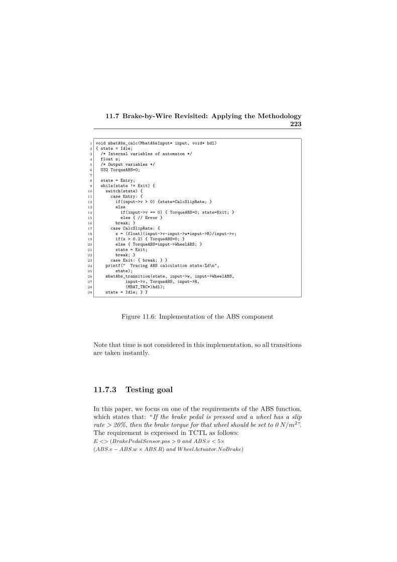
11.7 Brake-by-Wire Revisited: Applying the Methodology223
1 void mbatAbs_calc(MbatAbsInput* input, void* hdl)2 { state = Idle;3 /* Internal variables of automaton */4 float s;5 /* Output variables */6 U32 TorqueABS=0;78 state = Entry;9 while(state != Exit) {
10 switch(state) {11 case Entry: {12 if(input->v > 0) {state=CalcSlipRate; }13 else14 if(input->v == 0) { TorqueABS=0; state=Exit; }15 else { // Error }16 break; }17 case CalcSlipRate: {18 s = (float)(input->v-input->w*input->R)/input->v;19 if(s > 0.2) { TorqueABS=0; }20 else { TorqueABS=input->WheelABS; }21 state = Exit;22 break; }23 case Exit: { break; } }24 printf(" Tracing ABS calculation state:%d\n",25 state);26 mbatAbs_transition(state, input->w, input->WheelABS,27 input->v, TorqueABS, input->R,28 (MBAT_TRC*)hdl);29 state = Idle; } }
Figure 11.6: Implementation of the ABS component
Note that time is not considered in this implementation, so all transitionsare taken instantly.
11.7.3 Testing goal
In this paper, we focus on one of the requirements of the ABS function,which states that: “If the brake pedal is pressed and a wheel has a sliprate > 20%, then the brake torque for that wheel should be set to 0 N/m2”.The requirement is expressed in TCTL as follows:E <> (BrakeP edalSensor.pos > 0 and ABS.v < 5×(ABS.v −ABS.w ×ABS.R) and W heelActuator.NoBrake)

224 Paper F
11.7.4 Abstract test-case generation
As presented in Section 11.6.1, we employ Uppaal Port to generateabstract test-cases from the abstract model previously constructed. Themodel-checker takes as input the formal model together with the testgoal specified as the TCTL reachability property above.
1 State:(ABSFL.idle)2 ABSFL.w=0 ABSFL.wheelABS=0 ABSFL.torqueABS=-13 ABSFL.v=0 ABSFL.R=1/24 Transitions: ABSFL.idle->ABSFL.Entry { w:= 8, wheelABS:= 1,5 v:= 12}6 State:(ABSFL.Entry)7 ABSFL.w=8 ABSFL.wheelABS=1 ABSFL.torqueABS=-18 ABSFL.v=12 ABSFL.R=1/29 Transitions: ABSFL.Entry->ABSFL.CalcSlipRate { v> 0}
10 State:(ABSFL.CalcSlipRate)11 ABSFL.w=8 ABSFL.wheelABS=1 ABSFL.torqueABS=-112 ABSFL.v=12 ABSFL.R=1/213 Transitions: ABSFL.CalcSlipRate->ABSFL.Exit14 { v< 5* (v- w* R), torqueABS:= 0 }15 State: (ABSFL.Exit)16 ABSFL.w=8 ABSFL.wheelABS=1 ABSFL.torqueABS=017 ABSFL.v=12 ABSFL.R=1/218 Transitions: ABSFL.Exit->ABSFL.idle { }19 State:(ABSFL.idle)20 ABSFL.w=8 ABSFL.wheelABS=1 ABSFL.torqueABS=021 ABSFL.v=12 ABSFL.R=1/2
Figure 11.7: Abstract Test-Case
The Uppaal Port model-checker generates the witness trace pre-sented in Figure 11.7 automatically. The trace represents the executionof the pABSFL fp. Initially, the TA is in location idle and all variablesare zero. The first transition to state Entry is a read transition, wherethe latest variable values of w, wheelABS, and v are read. Since v > 0,the TA moves to the CalcSliprate location. On the transition to Exit,the torqueABS variable is set to zero, and after the write transition,the TA returns to the idle location.
Model-checking this particular instance has involved exploring 154182states out of 203384 stored ones, and the abstract test-case generationtook 3.27 seconds on a 1.8 GHz Intel Core i5 processor, with 8 GB ofRAM memory.

11.7 Brake-by-Wire Revisited: Applying the Methodology225
11.7.5 Python scripts generation
From the abstract test-case of Figure 11.7, the input variable valuesdetermining transitions in the TA model are identified automatically,and a Python test-script is generated. When executed by Farkle on thehost system, the script sends the signals representing those input valuesto the target. An excerpt of the generated script is shown in Figure 11.8.Lines 6-10 in the script set the content of the input signal with the initialvariable values, whereas line 11 encodes sending the signal to the target.The expected values of variables, as well as the expected order of visitedstates are defined in lines 13-18, according to the principles describedin Section 11.6.2. The log information sent back to the host, from thetarget, in the form of a signal is then received (line 20). Again, followingthe aforementioned principles, a set of assertion statements for checkingthe returned values versus the expected values are also generated as thebody of a loop, depicted in lines 23-39 of the script.
When the test-script is executed, an input signal is sent to the tar-get. Upon the receipt of a signal, the process to which the signal is sentstarts executing. The different states that a process enters are trackedand logged at runtime and during the execution of the code. This infor-mation is then sent back to the script, where it is checked whether theorder of the states at runtime and also the value of variables after eachstate change match the specification in the abstract test-case generatedfrom the TA models. To enable tracking of different states at runtime,the code is implemented in the form of deterministic state-machines, asshown in Figure 11.6. The Python script of Figure 11.8 delivers a "pass"verdict on the implementation of Figure 11.6.

226 Paper F
1 import sys2 import signals3 import xmlrunner4 ...5 # Sending input signal to ABSFL6 sig_send_ABSFL = signals.ABSFL_INPUT_SIG()7 sig_send_ABSFL.input.ABSFL_w = 88 sig_send_ABSFL.input.ABSFL_v = 129 sig_send_ABSFL.input.ABSFL_wheelABS = 1
10 sig_send_ABSFL.input.ABSFL_R = 111 self.linx.send(sig_send_ABSFL, self.pid_ABSFL)12 # Expected values13 ABSFL_w = [8, 8, 8]14 ABSFL_wheelABS = [1, 1, 1]15 ABSFL_torqueABS = [-1, -1, 0]16 ABSFL_v = [12, 12, 12]17 ABSFL_R = [0.5, 0.5, 0.5]18 ABSFL_state = [1, 2, 3]19 # Receive signals from test targets20 sig_recv_ABSFL = self.linx.receive21 ([signals.ABSFL_OUTPUT.SIGNO])22 # Testing of ABSFL23 for i in range(sig_recv_ABSFL.num_states):24 print "Transition %d:" %(i+1)25 self.assertEqual(sig_recv_ABSFL.states[i].state,26 ABSFL_state[i])27 print " state = %d" %sig_recv_ABSFL.states[i].state28 self.assertEqual(sig_recv_ABSFL.states[i].w, ABSFL_w[i])29 print " w = %d" %sig_recv_ABSFL.states[i].w30 self.assertEqual(sig_recv_ABSFL.states[i].wABS,31 ABSFL_wABS[i])32 print " wheelABS = %d" %sig_recv_ABSFL.states[i].wheelABS33 self.assertEqual(sig_recv_ABSFL.states[i].tABS,34 ABSFL_tABS[i])35 print " torqueABS = %d"36 %sig_recv_ABSFL.states[i].torqueABS37 self.assertEqual(sig_recv_ABSFL.states[i].v, ABSFL_v[i])38 print " v = %d" %sig_recv_ABSFL.states[i].v39 self.assertEqual(sig_recv_ABSFL.states[i].R, ABSFL_R[i])40 print " R = %d" %sig_recv_ABSFL.states[i].R41 ...
Figure 11.8: Generated Python script
11.7.6 Conformance between the abstract test-caseand the Python script
Our abstract test-case presented in Figure 11.7 can be represented op-erationally by a sequence of states and transitions as follows:(idle, w = 0, wheelABS = 0, torqueABS = −1, v = 0, R = 1/2)

11.8 Related Work 227
read(v,wheelABS,v)−−−−−−−−−−−−−−→(Entry, w = 8, wheelABS = 1, torqueABS = −1, v = 12, R = 1/2)v>0−−−→(CalcSlipRate, w = 8, wheelABS = 1, torqueABS = −1, v = 12, R = 1/2)v<5∗(v−w/R),torqueABS=0−−−−−−−−−−−−−−−−−−−−−→(Exit, w = 8, wheelABS = 1, torqueABS = 0, v = 12, R = 1/2)write(torqueABS)−−−−−−−−−−−−−→(idle, w = 8, wheelABS = 1, torqueABS = −1, v = 12, R = 1/2)
In a similar manner, the Python scripts give rise to the following:(ABSF L_state = 1, ABSF L_w = 8, ABSF L_wheelABS = 1,
ABSF L_torqueABS = −1, ABSF L_v = 12, ABSF L_R = 1/2)v>0−−−→(ABSF L_state = 2, ABSF L_w = 8, ABSF L_wheelABS = 1,
ABSF L_torqueABS = −1, ABSF L_v = 12, ABSF L_R = 1/2)v<5∗(v−w/R),torqueABS=0−−−−−−−−−−−−−−−−−−−−−→(ABSF L_state = 3, ABSF L_w = 8, ABSF L_wheelABS = 1,
ABSF L_torqueABS = 0, ABSF L_v = 12, ABSF L_R = 1/2)
In the above we have the following: the Entry state in the TA modelis ABSFL_state = 1 in the Python script. Given this, we observe thatthe trace generated from executing the Python script is included in thetrace generated by executing the TA model. Thus, it follows that we canactually use the Python script as a concrete test-case on the SUT, sothe abstract test-case of Figure 11.7 has proven to be a feasible abstracttest-case candidate.
11.8 Related WorkModel-based testing by model-checking is a technique introduced almostfifteen years ago [15] as an efficient way of using a model-checker tointerpret traces as test-cases. Some approaches to testing with model-checkers are applied on real-time reactive systems. Hessel et al. haveproposed test-case generation using the Uppaal model-checker for real-time systems [1] using timed automata specifications. In comparison, inour work we provide an approach suited to an architectural descriptionlanguage, and we offer an end-to-end tool-chain with support for test-

228 Paper F
case generation and execution.Over the last few years, researchers in the software testing commu-
nity have been investigating how design components and architecturedescription languages (ADLs) can be used for testing purposes. Thisled several research groups to develop concrete testing techniques forADLs[16, 17, 18]. Our framework allows the formal specification of boththe interface, and the internal behavior of each East-adl block as Up-paal Port TA. In addition, in this work we have provided functionaltest goals to be considered by the Uppaal Port model-checker, de-fined an executable semantics for the Uppaal Port TA, and describeda method for generating code that preserves the semantics of the TAmodel.
While a number of groups have made a distinction between abstractand concrete test cases [19, 20, 21], there are also differences in eachcase. For instance, Peleska [20] has proposed the RT-Tester tool-suitealong with the corresponding methodology, and discussed the two typesof test-cases, abstract and executable. The major goal in RT-Tester isto execute test-cases against the models of the system. In our work,we have introduced an approach that generates abstract test cases andthen concrete ones, which the latter are actually executable against therunning system in its target environment. In [22] based on a subset andpreliminary version of the approach (which is extended here in this work)and focusing only on the concrete test cases part, we have discussedhow having such executable test scripts to test the system behavior alsoserves as a method to verify architectural consistency. Finally, it isworth noting that there are different static analysis methods that canbe applied to ensure that expected properties in a system hold, thusincreasing confidence in its correctness. However, despite the applicationof such methods, there are still situations/systems where the resultsof such analysis may be invalidated at runtime due to different factors[23, 24]. In this work, we have tackled this issue by complementingformal verification of the system at the model level with the testing ofits behavior at runtime.
11.9 Conclusions and Future WorkIn this paper, we have presented a methodology for testing system im-plementations, starting from East-adl architectural models that are

11.10 Acknowledgment 229
extended by TA behavioral models. The methodology is supported by atool-chain consisting of ViTAL and Farkle, which can produce and runtest-cases automatically. The abstract test-cases for functional require-ments result by model-checking the “TA enriched” East-adl modelsin Uppaal Port. Next, such test-cases are transformed into Pythonscripts representing the executable test-cases that are finally run on theactual code that is implemented based on the (verified) formal model.Our work is an attempt to exercise the feasibility of test-case generationfrom East-adl models. The method has shown encouraging resultswhen applied on a Brake-by-Wire prototype from Volvo. As future work,we plan to also investigate abstract test-case generation for timing prop-erties of East-adl models, and integrate the results in our methodology.In addition, we envision extending our work towards other ADLs.
11.10 AcknowledgmentThe authors would like to thank Elaine Weyuker for her valuable com-ments on this work. This research has received funding from the ARTE-MIS JU, grant agreement number 269335, and from VINNOVA, theSwedish Governmental Agency for Innovation Systems, within the MBATproject, and also partially from the Swedish Knowledge Foundation(KKS) through the ITS-EASY industrial research school.


Bibliography
[1] Anders Hessel, Kim Larsen, Brian Nielsen, Paul Pettersson, andArne Skou. Time-Optimal Real-Time Test Case Generation Us-ing UPPAAL. In Lecture Notes in Computer Science, Formal Ap-proaches to Software Testing, pages 114–130. Springer Berlin Hei-delberg, 2004.
[2] Tretmans Jan. Model based testing with labelled transition systems.In Formal methods and testing, pages 1–38. Springer, 2008.
[3] Manoranjan Satpathy, Michael Leuschel, and Michael Butler.ProTest: An automatic test environment for B specifications. Elec-tronic Notes in Theoretical Computer Science, 111:113–136, 2005.
[4] Rajeev Alur and David L Dill. A theory of timed automata. Theo-retical computer science, 126(2):183–235, 1994.
[5] Aditya Agrawal, Gyula Simon, and Gabor Karsai. Semantic transla-tion of Simulink/Stateflow models to hybrid automata using graphtransformations. Electronic Notes in Theoretical Computer Science,109:43–56, 2004.
[6] John Håkansson and Paul Pettersson. Partial order reduction forverification of real-time components. In Formal Modeling and Anal-ysis of Timed Systems, pages 211–226. Springer, 2007.
[7] Eun-Young Kang, Eduard Paul Enoiu, Raluca Marinescu, CristinaSeceleanu, Pierre-Yves Schobbens, and Paul Pettersson. A method-ology for formal analysis and verification of EAST-ADL models.Reliability Engineering & System Safety, 120:127–138, 2013.
231

232 Bibliography
[8] John Håkansson, Jan Carlson, Aurelien Monot, Paul Pettersson,and Davor Slutej. Component-based design and analysis of em-bedded systems with uppaal port. In Automated Technology forVerification and Analysis, pages 252–257. Springer, 2008.
[9] Daniel Digerås. Integration between Optima and Farkle and ver-ification with a use case about file storage stack integration in aquality of service manager in OSE - Master Thesis. http://liu.diva-portal.org/smash/record.jsf?pid=diva2:624122, April 2011.
[10] The ATESST2 ATESST2 Consortium. EAST-ADL Profile Specifi-cation, 2.1 RC3 (Release Candidate). pages 10–75. www.atesst.org,2010.
[11] Johan Bengtsson, Bengt Jonsson, Johan Lilius, and Wang Yi. Par-tial order reductions for timed systems. In CONCUR’98 Concur-rency Theory, pages 485–500. Springer, 1998.
[12] Mark Utting, Alexander Pretschner, and Bruno Legeard. A taxon-omy of model-based testing approaches. Software Testing, Verifica-tion and Reliability, 22(5):297–312, 2012.
[13] Tobias Amnell, Elena Fersman, Paul Pettersson, Hongyan Sun, andWang Yi. Code synthesis for timed automata. Nord. J. Comput.,9(4):269–300, 2002.
[14] Wang Yi. CCS+ time= an interleaving model for real time sys-tems. In Automata, Languages and Programming, pages 217–228.Springer, 1991.
[15] André Engels, Loe Feijs, and Sjouke Mauw. Test generation for in-telligent networks using model checking. In Tools and Algorithms forthe Construction and Analysis of Systems, pages 384–398. Springer,1997.
[16] Antonia Bertolino and Paola Inverardi. Architecture-based soft-ware testing. In Joint proceedings of the second international soft-ware architecture workshop (ISAW-2) and international workshopon multiple perspectives in software development (Viewpoints’ 96)on SIGSOFT’96 workshops, pages 62–64. ACM, 1996.

[17] Henry Muccini, P Inverardi, and A Bertolino. Using software archi-tecture for code testing. Software Engineering, IEEE Transactionson, 30(3):160–171, 2004.
[18] Hassan Reza and Suhas Lande. Model based testing using softwarearchitecture. In Information Technology: New Generations (ITNG),2010 Seventh International Conference on, pages 188–193. IEEE,2010.
[19] C. Nebut, F. Fleurey, Y. Le-Traon, and J.-M. Jezequel. Automatictest generation: a use case driven approach. Software Engineering,IEEE Transactions on, 32(3):140–155, 2006.
[20] Jan Peleska. Industrial-Strength Model-Based Testing - State of theArt and Current Challenges. In Proceedings of the Eighth Workshopon Model-Based Testing, pages 3–28, March 2013.
[21] Wolfgang Prenninger, Mohammad El-Ramly, and Marc Horstmann.Chapter 15: Case Studies. In Manfred Broy, Bengt Jonsson, Joost-Pieter Katoen, Martin Leucker, and Alexander Pretschner, editors,Model-Based Testing of Reactive Systems: Advanced Lectures (Lec-ture Notes in Computer Science). Springer-Verlag New York, Inc.,Secaucus, NJ, USA, 2005.
[22] Mehrdad Saadatmand, Detlef Scholle, Cheuk Wing Leung, Sebas-tian Ullström, and Joanna Fredriksson Larsson. Runtime Verifica-tion of State Machines and Defect Localization Applying Model-based Testing. In Proceedings of the WICSA 2014 Companion Vol-ume. ACM, 2014.
[23] Mehrdad Saadatmand, Antonio Cicchetti, and Mikael Sjödin. De-sign of adaptive security mechanisms for real-time embedded sys-tems. In Proceedings of the 4th international conference on En-gineering Secure Software and Systems (ESSoS), pages 121–134,Berlin, Heidelberg, 2012. Springer-Verlag.
[24] S.E. Chodrow, F. Jahanian, and M. Donner. Run-time monitoringof real-time systems. In Real-Time Systems Symposium (RTSS),1991. Proceedings., Twelfth, pages 74–83, 1991.


Chapter 12
Paper G:Testing of TimingProperties in Real-TimeSystems: Verifying ClockConstraints
Mehrdad Saadatmand, Mikael SjödinThe 20th Asia-Pacific Software Engineering Conference (APSEC), Bangkok,Thailand, December, 2013.
235

Abstract
Ensuring that timing constraints in a real-time system are satisfied andmet is of utmost importance. There are different static analysis methodsthat are introduced to statically evaluate the correctness of such systemsin terms of timing properties, such as schedulability analysis techniques.Regardless of the fact that some of these techniques might be too pes-simistic or hard to apply in practice, there are also situations that canstill occur at runtime resulting in the violation of timing properties andthus invalidation of the static analyses’ results. Therefore, it is impor-tant to be able to test the runtime behavior of a real-time system withrespect to its timing properties. In this paper, we introduce an approachfor testing the timing properties of real-time systems focusing on theirinternal clock constraints. For this purpose, test cases are generatedfrom timed automata models that describe the timing behavior of real-time tasks. The ultimate goal is to verify that the actual timing behaviorof the system at runtime matches the timed automata models. This isachieved by tracking and time-measuring of state transitions at runtime.
12.1 Introduction 237
12.1 IntroductionIn building real-time systems, it is very important to ensure that timingproperties are in accordance with the specified timing requirements andconstraints. The correctness of these systems is not only dependent onthe correctness of the logical results of computations, but also on the timeat which the results are produced [1]. The criticality of this issue canvary from one real-time system to another, such as in a real-time mediaplayer vs. the airbag system in an automobile. Different methods havebeen suggested in order to verify the correctness of timing properties inreal-time systems. For example, there are diffeent schedulability analysismethods [2] that help to determine whether a set of real-time tasks areschedulable or not. There are several assumptions that are taken intoaccount in performing such analyses, for instance, Worst-Case Execu-tion Times (WCETs) of tasks. Some of the approaches for determiningexecution times can result in assigning very pessimistic values [3]. More-over, at runtime, situations may occur that lead to the violation of theassumptions that were taken into account for performing the analyses,and thus invalidation of the analysis results [4, 5]. It should also be notedthat for complex systems, such as those in telecommunication domainwith huge number of concurrent tasks handling big loads of calls, dataconnections, billing, routing, and so on, it can be very hard in practiceto get such detailed information about each task in the whole system inorder to perform schedulability analysis [4, 6].
In this paper, we introduce an approach to test the timing behavior ofreal-time systems at runtime. The main intention is to basically verifythat the timing properties of the tasks constituting the system matchthe specifications by testing the running system. This is achieved in ourapproach by consulting the timed automata models [7, 8, 9] of the systemand automatically generating test cases from them1. Timed automatamodels representing the timing constraints are used as the source for thegeneration of test cases and determining pass/fail criteria for them. Thetest cases when executed against the running system determine whetherthe observed timing behaviors match what is specified for the tasks in
1In this paper, the term verify is used as its ordinary meaning in English andnot to refer to ’formal verification’ in software engineering, unless explicitly stated.Moreover, the term state machine is used as a synonym to refer to a timed automatonwhenever the main concern is only the states and transitions in the model regardlessof the timing specifications.

238 Paper G
the timed automata models or not. The focus in this work is mainly onthe verification of the clock constraints that are specified in the models.
While most of the methods for verification of timing properties mainlytarget development phases before the actual execution of a real-timesystem, such as static analysis and model checking methods [1], our ap-proach provides a way to dynamically test and verify the actual runningsystem. This is especially important to alleviate the issues mentionedabove, particularly scenarios which may occur at runtime that can causeinvalidation of the results of static analysis methods, and to identify suchmisbehaviors. On the other hand, the approach can also be very wellused to complement static analysis methods to gain more confidence inthe correctness of designed systems in terms of their timing properties.We demonstrate the applicability of our approach by using it for testingof timing properties in a Brake-By-Wire (BBW) system from automo-tive industry. As the platform for implementation of the system, we haveused OSE Real-Time Operating System (RTOS) [10], on top of which,BBW application is developed in C/C++.
The remainder of the paper is structured as follows. In Section 12.2,background information about the used technologies and the BBW sys-tem is provided. Section 12.3 describes the details of the proposed ap-proach and in Section 12.4, we discuss how we have implemented theapproach and applied it on the BBW system. In Section 12.5, relatedworks are discussed and possible scenarios for combination of our ap-proach with those works are also identified. Finally in Section 12.6, asummary of the paper along with highlights and conclusions are pro-vided.
12.2 Background Context12.2.1 Timed AutomataTimed Automata (TA) are essentially finite state machines which areannotated and extended with real-valued clocks [7, 8, 9]. The clocks, ini-tially set to zero at system start-up, progress and increase synchronouslyand at the same rate. The value of clocks can also be reset if needed.Timed automata are used to provide an abstract model of real-time sys-tems. Timing constraints are specified using clocks whose values canbe checked in the form of guards and invariants. Invariants can be re-garded as progress conditions and are used to restrict the way that time

12.2 Background Context 239
may elapse at a state (location). For example, using invariants, it can bespecified that the system is not allowed to stay in a state more than sometime units and the transition has to be taken by the specified amount oftime. Guards are specified on a transition (edge) as conditions to restrictits temporal occurrence.
Figure 12.1 shows an example timed automata for modeling a real-time lamp introduced in [8]. In this system, there is a timing requirementon how the user presses a button. The action of the user in pressing thebutton is modeled with the right-hand automaton. The timing require-ment in this example states that if the user presses the button, the lampis switched off or on (on in the low mode). However, if he is fast enoughin pressing the button again, the lamp is switched on and ends up in thebright mode. The decision whether the user has been fast in pressingthe button or not is determined by using the clock y.
Figure 12.1: TA model of a real-time lamp [8]
12.2.2 OSE RTOS & FarkleOSE is a commercial and industrial real-time operating system devel-oped by Enea [10] which has been designed from the ground specifi-cally for fault-tolerant and distributed systems. It provides preemptivepriority-based scheduling of tasks. OSE offers the concept of direct andasynchronous message passing for communication and synchronizationbetween tasks, and OSE’s natural programming model is based on thisconcept. Linx, which is the Inter-Process Communication protocol (IPC)in OSE, allows tasks to run on different processors or cores, utilizing thesame message-based communication model as on a single processor. This

240 Paper G
programing model provides the advantage of not needing to use sharedmemory among tasks. The runnable real-time entity equivalent to atask is called process in OSE, and the messages that are passed betweenprocesses are referred to as signals (thus, the terms process and task inthis paper can be considered interchangeably). Processes can be createdstatically at system start-up, or dynamically at runtime by other pro-cesses. Static processes last for the whole life time of the system andcannot be terminated. Types of processes that can be created in OSEare: interrupt process, timer interrupt process, prioritized process, back-ground process, and phantom process. A process can be in one of thefollowing states: ready, running or waiting. One interesting feature ofOSE is that the same programming model based on signal passing canbe used regardless of the type of process.
Farkle is a test execution framework that is originally developed fortesting systems built using OSE. It enables testing embedded systemsin their target environments. This capability has become possible byusing the signal passing mechanism of OSE which allows Farkle to runon a host machine and communicate with the target by passing signals.In other words, Farkle basically enables testing an embedded system byproviding certain inputs to the target in the form of signals and receivingthe result as signals containing output values. The test scripts that areused to send and receive signals, and also decide the verdict of test casesare implemented in Python. Figure 12.2 provides an overall idea on howFarkle works.
Figure 12.2: Farkle test execution environment.

12.2 Background Context 241
12.2.3 Brake-by-Wire SystemThe Brake-by-Wire (BBW) is a braking system in which mechanicalparts are replaced by electronic sensors and actuators and thus remov-ing the hydraulic connections between the brake pedal and each wheelbrake. Anti-lock Braking System (ABS) is usually an inherent func-tionality provided by BBW systems [11]. The purpose with the ABSsubsystem is to prevent locking of the wheels by controlling brakingbased on calculated slip rate value. Slip rate is calculated according tothe following formula (where r is the radius of the wheel):
s = (vehicleSpeed− wheelSpeed ∗ r)/vechileSpeed
If s is greater than a certrain limit, then the brake actuator is re-leased and no brake is applied, otherwise the requested brake torque isused. The Electronic Control Unit (ECU) for each wheel will have threeapplication software components: one is a sensor to measure the wheelspeed, one is an actuator for the brake, and the third one implementsthe ABS controller for the wheel. A schematic view of the BBW sys-tem components is shown in Figure 12.3 considering only one wheel forbrevity.
Figure 12.3: Components composing a BBW system
There are several timing requirements in BBW systems. For exam-ple, the total brake reaction delay could be specified not to be more than

242 Paper G
200ms (in a sample implementation of the BBW system), or require-ments on the periods of samplings done by sensors. Generally, BBW isan example of safety-critical, distributed and real-time systems in whichmeeting timing requirements has also direct impacts on the safety of thesystem.
A Timed Automata (TA) model, designed in Uppaal tool [8], de-scribing the internal behavior of the ABS component of BBW system isshown in Figure 12.4. In this model, y is a clock whose specification onthe states indicates the amount of time units that can be spent in eachstate (non-deterministically, between 0 and the specified value) beforea transition has to be made to the next state. These timing specifica-tions are naturally derived from high level timing requirements of theBBW system and its components. The values in the TA model here arejust samples, and the exact values for each implementation of the BBWsystem might be different.
Figure 12.4: Timed automata model of the ABS component
12.3 Proposed ApproachIn this section we describe our proposed approach to generate test casesin order to verify that the timing properties of the system at runtimematch the clock constraints specified in the timed automata models ofthe system. This is made possible basically by annotating the codeso that state changes can be determined and tracked at runtime, andmeasuring the time difference between the state changes. The followingare the steps that constitute the approach:

12.3 Proposed Approach 243
1. Based on the automata models, C/C++ enumerations (enum) thatrepresent each state machine and their internal states are gener-ated. These enumeration structures are stored in a C/C++ filealong with a helper function called set_state_wtime(StateMachine,State). The file is then included in the implementation code ofthe target application (i.e., to be tested).
2. The states in the timed automata model are mapped to the codeusing the above helper function. This is done by adding calls tothe set_state_wtime() helper function at places where a statechange occurs in the code. The helper function basically logs thenew state belonging to the specified state machine along with thetime stamp at which the transition and change to the new statehas occurred.
3. According to the timing specifications in the timed automata model,a test script is generated which verifies the measured time dif-ference between (pairs of) consecutive states against the model.In other words, if the time difference and also the order of statechanges match the model, then the result of the test is determinedas pass, otherwise a fail verdict is decided.
The generation of executable test scripts described in Step 3 is donein the following way:
• Minimum number of paths covering all clock constraints in thetimed automata model are identified (clock constraint coverage).For example, in case of the TA model of the ABS componentshown in Figure 12.4, the following paths are selected: Entry →CheckSpeed → AsigT1 → Exit and Entry → CalcSlipRate →AsigT2→ AsigT3→ Exit.
• For each of the identified paths a test script is generated. Thescript basically provides and sends necessary input(s) causing thestate machine to start from the Entry state, taking the states andtransitions constituting the selected path until reaching the Exitstate. Considering the example in Figure 12.4, this means provid-ing a value for wABS variable resulting in a value for V causingthe desired transition and path to be taken. Based on the log infor-mation generated by the helper function, the script checks whetherthe order of the states and the time spent in each state with a clock

244 Paper G
constraint match the extracted path from the timed automata ornot.
12.4 Application & Implementation of theApproach
We have implemented the BBW system on OSE 5.5.1. An OSE process iscreated and developed for each component shown in Figure 12.3, and thecommunication between them is implemented by defining and passingappropriate OSE signals. For example, the signal definition for passingwheel speed information between processes is shown in Listing 12.1.
Listing 12.1: Signal definition for wheel speed#define WHEEL_SPEED_SIG 1026typedef struct WheelSpeedSignal {
SIGSELECT sigNo ;f loat WheelSpeed ;
} WheelSpeedSignal ;
To test and verify the clock constraints in the running system, theapproach described in the previous section is followed. First informa-tion about different states is extracted from the timed automata modelsand enumeration structures (C/C++ enums) representing them are au-tomatically generated:
enum StateMachines {BrakePedalSensor , BrakeTorqueCalculator ,GlobalBrakeContro l l e r , WheelActuator , ABS, WheelSensor } ;
enum Sta t e s {Entry , CheckSpeed , CalcSl ipRate , AsigT1 , AsigT2 ,AsigT3 , Exit , Brake , NoBrake , Reac , . . . } ;
The result of this step is a C/C++ file containing the generateddata structures along with the aforementioned helper function (that hasa fixed implementation), which is then included in the implementationcode of the BBW-ABS system. The next step is to map the statesin the timed automata models to the code by adding calls to the helperfunction. The result is depicted in Figure 12.5 in case of the ABS process.
This is the only manual step in the whole approach. This step mayalso be automated if in a model-driven development methodology, for

12.4 Application & Implementation of the Approach 245
Figure 12.5: Mapping of states to the code (ABS function)
example, the code is generated taking into account the timed automatamodels of the system and thus aware of different states and transitions.
The final step is the generation of executable test scripts. For eachidentified path for covering the clocks constraints in the model, a testscript is generated which, by investigating the generated log informationabout state changes, verifies that:
1. the order of visited states is in accordance with the timed automatamodel,
2. the amount of time spent in each state matches the timing speci-fications in the timed automata model. This is done by consultingthe time stamps associated with and logged for each state change.
These details (order of states and timing specifications) are inherentand present in the timed automata models and are extracted from themin generating test scripts.
The test scripts are generated in the form of Python scripts whichare then executed by the Farkle test execution framework (describedin Section 12.2.2). Farkle which runs on the host machine enables testscripts to communicate with the target system. The scripts send signalsto the BBW processes running on the target. These signals (e.g., wheelspeed signal in Listing 12.1) contain input values which are received,

246 Paper G
extracted and acted upon by the recipient process. In terms of statemachines in the models, passing these input values invoke transitions inthe recipient process’s internal states. Whenever during the execution ofa process the set_state_wtime(StateMachine,State) helper function(added during the mapping step) is called, a log record is created fortracking the states and the time point that a state change has occurred.This is used by test scripts to determine test verdicts. Finally, the passor fail results returned by executing the test scripts show whether theactual behavior of the system at runtime has been in accordance withand respecting the constraints specified in the timed automata modelsor not.
12.5 Related WorkIn [12], we have previously introduced an approach for monitoring oftiming properties of real-time tasks at runtime by enriching schedulerswith the necessary monitoring mechanisms. The approach does not onlyenable provision of information about timing properties such as actualexecution time (vs. estimated WCET), response time, deadline misses,and observed period and Minimum Inter-Arrival Time (MIAT) of tasks,but also helps to preserve and enforce such properties at runtime. Inother words, if, for example, a task is taking too much time than itsallowed time budget, this time budget is enforced by preempting thetask, to let other tasks in the system perform as expected and pre-determined. Although in [12], we have not explicitly discussed and dealtwith testing of such timing properties, the approach and the monitoringmechanisms introduced there can be regarded as the core functionalityneeded for dynamic testing of properties such as execution time of tasks,determining occurrence of deadline misses in the system, violation ofperiod and MIAT values, and so on. In this paper, however, we moredirectly addressed testing of real-time systems. Moreover, we focusedmainly on timing properties specifiable in the form of timed automatadescribing the internal behavior of real-time tasks, as well as the systemin general (e.g., end-to-end deadlines). Extending the work done in [12]for testing purposes, and combining it with the approach suggested hereto provide a comprehensive testing framework for timing properties isleft as future directions of this work to investigate. Beside the monitoringmethod we have introduced in [12], we have also provided a survey of

12.5 Related Work 247
different available methods and tools for monitoring of timing constraintsin [13].
Uppaal is a tool suite for modeling and verification of real-time sys-tems modeled as networks of timed automata [8, 14]. Three main partsthat constitute Uppaal are a description language, a simulator and amodel-checker. Uppaal is an example of prominent tools and meth-ods for verification of real-time systems at the modeling level and doesnot concern implementation code and actual execution of the system.Uppaal TRON [15, 16] is a testing tool based on the Uppaal enginethat is designed for black-box conformance testing of real-time systems.The testing approach provided by TRON is similar to ours in the sensethat both communicate with and execute test cases against the runningsystem, and also both use timed automata models. Uppaal TRON de-rives, executes, and evaluates test cases against the implementation ofthe system in real-time. However, the main difference between the test-ing method of Uppaal TRON and our approach is that Uppaal TRONaddresses online generation and execution of test cases based on the re-sults of previous executed test cases, and focuses mainly on observableinput and output actions considering the Implementation Under Test(IUT) as black-box and assuming that its internal states are not observ-able [16]. While in our approach, test cases are only generated offline,and also the IUT is considered as white-box whose internal state changesare fully tracked and compared against the TA models. The mapping ofstates to code in our approach is thus needed and introduced to enablethis feature. Also what is tested in our approach is not the output fromthe IUT and the time at which it is produced, but the order of statesand the time spent in each one which has a time constraint. From thisperspective, there seems to be potentials for combining our testing ap-proach with Uppaal TRON. Shin, Drusinsky and Cook present in [17]an approach for white-box testing of timing properties. They introduceassertion state charts as a way to specify and keep track of timing con-straints. From these state charts, some test cases are derived manually(e.g., testing single use case scenarios) and some are automatically gen-erated (e.g., testing the state chart under test itself). Their approachis however closer to Uppaal TRON with respect to what is actuallytestable and tested in the running system.
In [18], we have discussed the general idea of combining static analysisand testing. Its potentials and different combination scenarios along withan example are also provided in that work.

248 Paper G
12.6 ConclusionIn this paper, we introduced an approach for dynamic testing of timingproperties in real-time systems. By tracking state changes at runtime,the approach allows for more detailed testing of timing properties of real-time systems and their tasks whose internal behaviors are representedin the form of timed automata. Testing and runtime verification oftiming properties becomes especially important in cases where staticanalysis methods are hard to apply in practice or can be invalidated atruntime. In general, however, both approaches (static analysis methodsand testing) can be considered complementary and used together to gainmore confidence in temporal correctness of real-time systems.
Timed automata models are used in our approach as a representa-tion and source for timing requirements and constraints from which testcases are automatically generated. We demonstrated the applicabilityof our approach on the ABS subsystem of Brake-By-Wire system, veri-fying the timing constraints specified on different states constituting itsbehavioral model. Also, as for the implementation of our approach, weused OSE as the core platform and real-time operating system, C/C++for implementing the BBW application, and Python as the languagefor generating executable test scripts. Using OSE along with its testexecution environment, Farkle, enables to test an embedded system inits target environment. This is a valuable feature considering that re-source constraints originating from the execution environment (e.g., bat-tery/power, layout and size, heat generation, available memory, CPU,etc.) affect and dictate, to a great degree, how an embedded systemshould be designed and perform. It should, however, be noted that theapproach is not necessarily dependent on these technological choices andmay be well implemented differently.
As mentioned in the paper, the mapping step of the approach, inwhich state changes are annotated and marked in the code using thehelper function, is the only step which needs manual intervention. As afuture work, we are working on solutions for automating this step, andthus automating the whole testing approach. Also, in this work, sincewe were only interested in the time difference between state changes,the execution time of the added calls to the helper function (to log andtimestamp state changes) had no effect on the test result and was simplyignored. However, if, for example, end-to-end response times are to betested, it is important to take into account the added timing-cost of

12.7 Acknowledgements 249
the helper function. Considering that the helper function has a fixedexecution time, though, its impacts on the execution time of a task towhich it is added may be easily predicted and reduced from the task’stotal execution time. Also, it might be possible to claim that in somesystems, if tests are passed while having helper function calls in thecode, they might also work fine in terms of timing properties when thehelper function calls are removed, e.g., in the release and final version ofa product. Careful investigation of such claims and scenarios, and sideeffects of adding helper functions to enable testing, as well as differentways to mitigate them are left as other future directions of this work.
12.7 AcknowledgementsThis work has been supported by the MBAT European Project [19]and Xdin Stockholm AB (formerly Enea Services Stockholm AB) [20]through the ITS-EASY industrial research school [21]. The researchleading to these results has received funding from the ARTEMIS JointUndertaking under grant agreement no 269335 (see Article II.9. of theJU Grant Agreement) and from the Swedish Governmental Agency forInnovation Systems (VINNOVA). We would also like to thank RalucaMarinescu and Cristina Seceleanu for their technical tips and supportfor this work.


Bibliography
[1] Joachim Wegener and Matthias Grochtmann. Verifying TimingConstraints of Real-Time Systems by Means of Evolutionary Test-ing. Real-Time Syst., 15(3):275–298, November 1998.
[2] Robert I. Davis and Alan Burns. A survey of hard real-time schedul-ing for multiprocessor systems. ACM Comput. Surv., 43(4):35:1–35:44, October 2011.
[3] Reinhard Wilhelm, Jakob Engblom, Andreas Ermedahl, Niklas Hol-sti, Stephan Thesing, David Whalley, Guillem Bernat, ChristianFerdinand, Reinhold Heckmann, Tulika Mitra, Frank Mueller, Is-abelle Puaut, Peter Puschner, Jan Staschulat, and Per Stenström.The worst-case execution-time problem-overview of methods andsurvey of tools. ACM Trans. Embed. Comput. Syst., 7(3):36:1–36:53,May 2008.
[4] Mehrdad Saadatmand, Antonio Cicchetti, and Mikael Sjödin. De-sign of adaptive security mechanisms for real-time embedded sys-tems. In Proceedings of the 4th international conference on En-gineering Secure Software and Systems, ESSoS’12, pages 121–134,Eindhoven, The Netherlands, 2012. Springer-Verlag.
[5] S.E. Chodrow, F. Jahanian, and M. Donner. Run-time monitor-ing of real-time systems. In Real-Time Systems Symposium, 1991.Proceedings., Twelfth, pages 74 –83, dec 1991.
[6] Mehrdad Saadatmand, Antonio Cicchetti, and Mikael Sjödin. UML-Based Modeling of Non-Functional Requirements in Telecommuni-cation Systems. In The Sixth International Conference on SoftwareEngineering Advances (ICSEA), October 2011.
251

252 Bibliography
[7] Rajeev Alur and David L. Dill. A theory of timed automata. The-oretical Computer Science, 126(2):183 – 235, 1994.
[8] Gerd Behrmann, Re David, and Kim G. Larsen. A tutorial on Up-paal 4.0. http://www.it.uu.se/research/group/darts/papers/texts/new-tutorial.pdf, November 2006.
[9] Johan Bengtsson and Wang Yi. Timed Automata: Semantics, Al-gorithms and Tools. In W. Reisig and G. Rozenberg, editors, InLecture Notes on Concurrency and Petri Nets, Lecture Notes inComputer Science vol 3098. Springer–Verlag, 2004.
[10] Enea. http://www.enea.com, Last Accessed: June 2013.
[11] S. Anwar. An anti-lock braking control system for a hybrid elec-tromagnetic/electrohydraulic brake-by-wire system. In AmericanControl Conference, 2004. Proceedings of the 2004, volume 3, pages2699–2704 vol.3, 2004.
[12] M. Saadatmand, M. Sjodin, and N.U. Mustafa. Monitoring capa-bilities of schedulers in model-driven development of real-time sys-tems. In 17th IEEE Conference on Emerging Technologies FactoryAutomation (ETFA), pages 1–10, Krakow, Poland, 2012.
[13] Nima Asadi, Mehrdad Saadatmand, and Mikael Sjödin. Run-TimeMonitoring of Timing Constraints: A Survey of Methods and Tools.In The Eighth International Conference on Software EngineeringAdvances (ICSEA), Venice, Italy, October 2013.
[14] Uppaal. http://www.uppaal.org/, Accessed: August 2013.
[15] Uppaal for Testing Real-Time Systems Online (TRON). http://people.cs.aau.dk/~marius/tron/, Accessed: August 2013.
[16] Kim G. Larsen, Marius Mikucionis, Brian Nielsen, and Arne Skou.Testing real-time embedded software using UPPAAL-TRON: an in-dustrial case study. In Proceedings of the 5th ACM internationalconference on Embedded software, EMSOFT ’05, pages 299–306,New York, NY, USA, 2005. ACM.
[17] Man-Tak Shing, D. Drusinsky, and T.S. Cook. Quality assuranceof the timing properties of real-time, reactive system-of-systems. In

2006 IEEE/SMC International Conference on System of SystemsEngineering, pages 6 pp.–, 2006.
[18] Mehrdad Saadatmand and Mikael Sjödin. On Combining Model-Based Analysis and Testing. In 10th International Conference onInformation Technology : New Generations (ITNG 2013), Las Ve-gas, NV, USA, April 2013.
[19] MBAT Project: Combined Model-based Analysis and Testing ofEmbedded Systems. http://www.mbat-artemis.eu/home/, Ac-cessed: June 2013.
[20] XDIN AB. http://xdin.com/en/about-xdin/enea-experts/,Accessed: June 2013.
[21] ITS-EASY post graduate industrial research school for embed-ded software and systems. http://www.mrtc.mdh.se/projects/itseasy/, Accessed: June 2013.