Embed Size (px)
Citation preview

IDG, CEERI, Pilani.
VHDL Tutorial
Presenter : Ravi Saini
Tel : 01596-242359 E-Mail : [email protected]
IC Design Group CEERI, Pilani - 333 031Rajasthan, India
IDG, CEERI, Pilani.
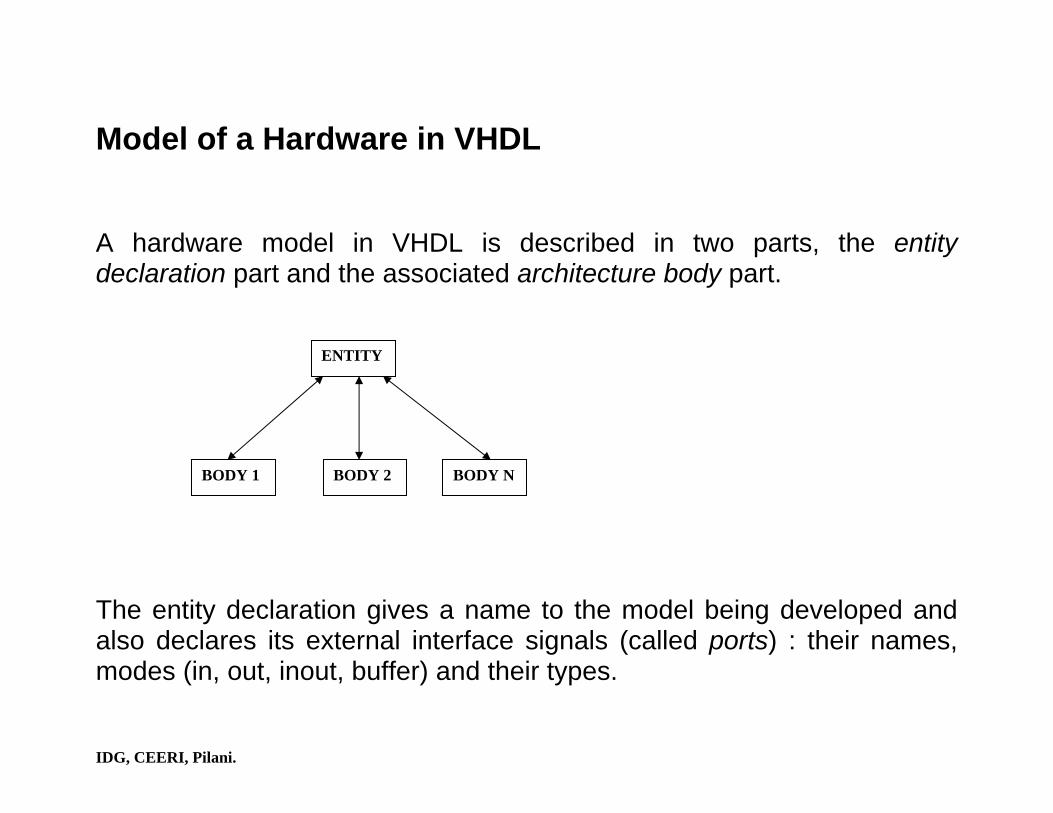
Model of a Hardware in VHDL A hardware model in VHDL is described in two parts, the entity declaration part and the associated architecture body part. The entity declaration gives a name to the model being developed and also declares its external interface signals (called ports) : their names, modes (in, out, inout, buffer) and their types.
ENTITY
BODY 1 BODY 2 BODY N

IDG, CEERI, Pilani.
What is Synthesis? Synthesis is the process of constructing a gate-level netlist from a model of a circuit described in VHDL. A synthesis program generates a RTL netlist (FF’s, ALU, multiplexer, interconnected by wires). So, the RTL module builder is necessary and the purpose of this builder is to build each of the required RTL blocks from a library of predefined components (user-specified target technology). After producing a gate-level netlist, a logic optimizer reads in this netlist and optimizes the circuit for the user-specified area and timing constraints.

IDG, CEERI, Pilani.
Synthesis
VHDL model
RTL module builder Target
technology
Area and Timing constraints
Unoptimized Gate level netlist
Logic optimizer
Optimized Gate level netlist
The synthesis process

IDG, CEERI, Pilani.
Literals (enumeration, integer, ….) Data types (enumeration types, record types,….) Data objects (variables, constants, signals) Statements (signal assignment, if, case, ……) Structure (process, block, component, …..)
Values (logic-0, logic-1, don’t-care, floating, unknown) Elements (wire, latch, flip-flop, ALU, multiplexer,……)
Hardware world
VHDL world

IDG, CEERI, Pilani.
Questions to ask are: • How are literals mapped to logic values?
• How does a data type translate to hardware?
• How do data objects map to hardware?
• How are statements translated to hardware?

IDG, CEERI, Pilani.
Synthesis in a design process A circuit can be described in many different ways, not all of which may be synthesizable. This is due to the fact that VHDL was designed primarily as simulation language and not for synthesis. There is no standardized subset of VHDL for synthesis. There is no direct object in VHDL that means a latch or a flip-flop, therefore, each synthesis system provide different mechanism to model a flip-flop or a latch.
Circuit
Style A Style B Style C Style D
Models

IDG, CEERI, Pilani.
Value Holders for Hardware Modeling VHDL provides two classes of data objects, signal and variable, that can be used to model the basic value holders in hardware. The basic value holders in hardware are
• Wire • Flip-flop (an edge-triggered device) • Latch (a level-sensitive device)

IDG, CEERI, Pilani.
In VHDL, a signal, or a variable declared in a process, retains its value through the entire simulation run, thus inferring memory. Example : signal A, B, C, Z : bit; ……. No_memory : process(A, B, C) variable temp : bit; begin temp := A and B; Z <= temp or C; end process; VHDL semantics says that variable temp retains its value through the entire simulation run.

IDG, CEERI, Pilani.
Logic generated after synthesis is
A
B
C
tempZ
IDG, CEERI, Pilani.
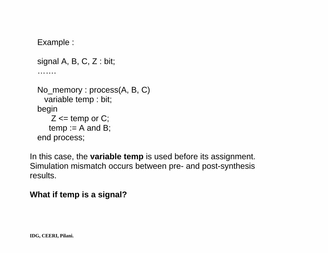
Example : signal A, B, C, Z : bit; ……. No_memory : process(A, B, C) variable temp : bit; begin Z <= temp or C; temp := A and B; end process;
In this case, the variable temp is used before its assignment. Simulation mismatch occurs between pre- and post-synthesis results. What if temp is a signal?

IDG, CEERI, Pilani.
Computing Bit-widths Signal A : integer range 0 to 15; Type MYINT is range –128 to +15; Variable B : MYINT; Variable Z : integer; A synthesis system may automatically determine the size of Z by performing a data-flow analysis of the model. Example: Z <= Ax + By; Note: Use signed and unsigned type defined in arithmetic packages (numeric_bit and numeric_std).

IDG, CEERI, Pilani.
Arithmetic Operators Library ieee; Use ieee.std_logic_1164.all; Use ieee.numeric_std.all; Entity adder is port( A : in signed (3 downto 0); B : in unsigned (3 downto 0); Result1 : out signed (3 downto 0); Result2 : out unsigned (3 downto 0)); end adder; architecture arith of adder is begin Result1 <= A + “11”; Result2 <= B + “11”; end arith;

IDG, CEERI, Pilani.
There are two adders synthesized in this example. In the first assignment statement, the right operand “11” is sign-extended to 4 bits before the addition is performed. In the second assignment statement, the right operand “11” is zero-extended to 4 bits before the addition is performed. Computing result size • +, - : Result size is the larger of input1’length and input2’length
where input1 and input2 are the two operands. • * : Result size is input1’length + input2’length.
• / : Result size is input1’length.

IDG, CEERI, Pilani.
Modeling a Carry Example : Signal A : unsigned (5 downto 0); Signal result : unsigned (6 downto 0); …………. Result <= (‘0’ & A) + 1;

IDG, CEERI, Pilani.
Sequential and combinational logic can be synthesized from a VHDL description. Combinational logic can be described : • Using concurrent signal assignment statements. • Using sequential statements in a process.
Synchronous logic elements (FF’s, latches) can be inferred by describing statements within a process in a certain style. The target of a signal or variable assignment is a wire, a flip-flop, or a latch is decided by the context under which the assignment statement appears.

IDG, CEERI, Pilani.
Example :
signal flop : bit; ……. Inferring_FF : process(clk) begin If RISING_EDGE(clk) then flop <= input; end if; end process;

IDG, CEERI, Pilani.
A variable holds a temporary value and does not necessarily infer an unique wire in hardware. Example : L1 : process(A, B, C)
variable t1, t2 : bit; begin
t1 := A and B; t2 := t1 and C; t1 := t2 and A; Z <= t1 and t2;
end process;
A
B
C
t1
t2
t1 Z

IDG, CEERI, Pilani.
An example where latch is inferred :
signal A, B, C : bit; ……. LATCH : process(A, C) variable temp : bit; begin If (A = ‘0’) then temp := C; end if; B <= not temp;
end process; If a variable declared inside a process, or a signal, is not assigned in all the branches of an if statement, then a latch is inferred. What about variable declared in a subprogram??
IDG, CEERI, Pilani.
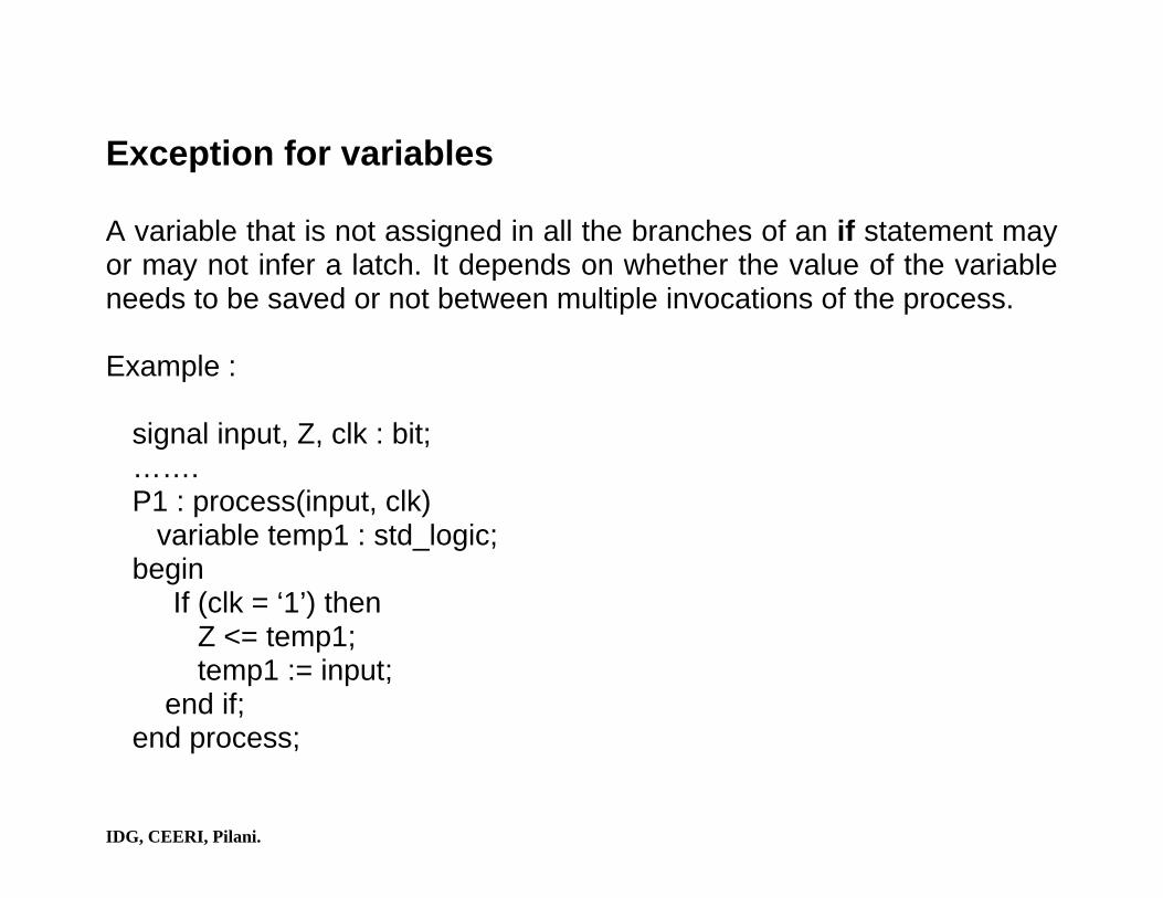
Exception for variables A variable that is not assigned in all the branches of an if statement may or may not infer a latch. It depends on whether the value of the variable needs to be saved or not between multiple invocations of the process. Example :
signal input, Z, clk : bit; ……. P1 : process(input, clk) variable temp1 : std_logic; begin If (clk = ‘1’) then Z <= temp1; temp1 := input; end if; end process;

IDG, CEERI, Pilani.
P2 : process(input, clk) variable temp2 : std_logic; begin If (clk = ‘1’) then temp2 := input; Z <= temp2; end if; end process;
In process P1, the variable temp1 is read before it is assigned. So, the value of temp1 needs to be saved between multiple iterations of the process. Thus temp1 becomes a latch. In process P2, the variable temp2 is first assigned a value and then its value is read. So there is no need to save the value of temp2. In this case temp2 is not synthesized to a latch.

IDG, CEERI, Pilani.
General Rules for latch inferencing Rule 1 : A variable is assigned in a conditional statement (if or case). Rule 2 : Variable is NOT assigned in all branches of conditional statement. Rule 3 : Value of variables need to be saved between multiple invocations of the process. All the three conditions must be satisfied before a variable is inferred as a latch.

IDG, CEERI, Pilani.
Avoiding Latches There are two ways of avoiding a latch. In the first approach define a value for the variable in the else branch of an if statement. Example :
signal A, B, C : bit; ……. LATCH : process(A, C) variable temp : bit; begin If (A = ‘0’) then temp := C; else temp := ‘0’; end if;
end process;

IDG, CEERI, Pilani.
In the second approach, initialize the value of the variable before the if statement. Example :
signal A, B, C : bit; ……… LATCH : process(A, C) variable temp : bit; begin temp := ‘0’; -- value of variable is initialized. If (A = ‘0’) then temp := C; end if;
……… end process;

IDG, CEERI, Pilani.
Wait Statement There are three basic forms of wait statement in VHDL : wait for time; wait until condition; wait on signal-list; The wait-until form is supported for synthesis. The wait statement with the various forms of clock expressions that are allowed are : wait until clock_name = clock_value; wait until clock_name = clock_value and clock_name’EVENT; wait until clock_name = clock_value and clock_name’STABLE; wait until RISING _EDGE (clock_name); wait until FALLING_EDGE (clock_name);

IDG, CEERI, Pilani.
A flip-flop can also be inferred by using a special if statement in a process. The difference between the if statement style and the wait statement style : • In the if statement style, more than one clock can be modeled in a
single process and also the combinational logic and sequential logic can be described in a single process.
• In the wait statement style, logic associated with each clock has to be described in a different process and synchronous logic has to be separated from combinational logic.
IDG, CEERI, Pilani.
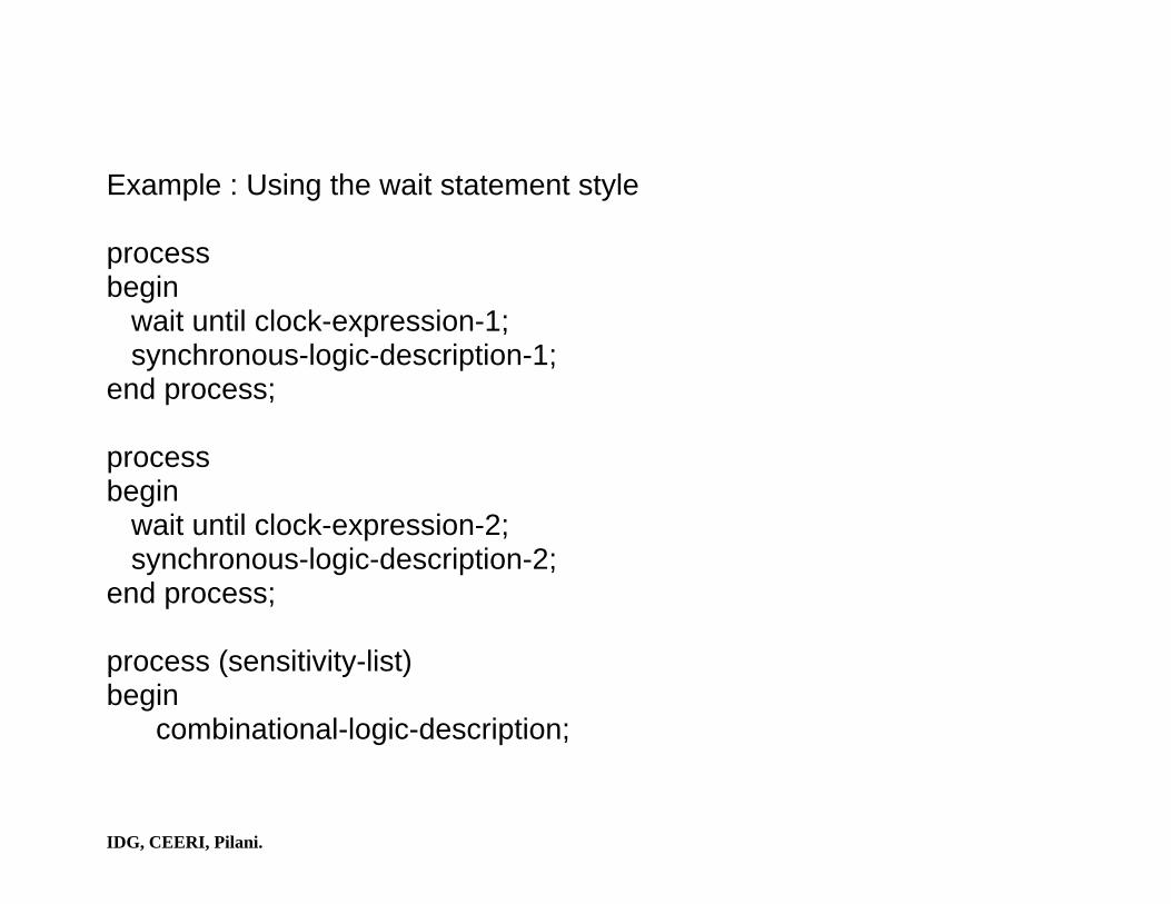
Example : Using the wait statement style process begin wait until clock-expression-1; synchronous-logic-description-1; end process; process begin wait until clock-expression-2; synchronous-logic-description-2; end process; process (sensitivity-list) begin combinational-logic-description;

IDG, CEERI, Pilani.
end process; Example : Using the if statement style Process (sensitivity-list-with-clocks) begin if (clock-expression-1) then; synchronous-logic-description-1; end if; if (clock-expression-2) then; synchronous-logic-description-2; end if; combinational-logic-description; end process;

IDG, CEERI, Pilani.
Inferring Flip-flops with Asynchronous Preset and Clear if (condition-1) then; asynchronous-logic-1; elsif (condition-2) then; asynchronous-logic-2; elsif (condition-3) then; asynchronous-logic-3;
-- Any number of elsif’s ………….. elsif clock-expression then synchronous-logic;
end if;

IDG, CEERI, Pilani.
Example : Library ieee; Use ieee.std_logic_1164.all; Use ieee.numeric_std.all; Entity updown_counter is port( clk, preset, updown, clear : in std_logic; input : in std_logic_vector (1 downto 0); output : out std_logic_vector (1 downto 0)); end updown_counter; architecture arith of updown_counter is signal counter : unsigned (1 downto 0); begin process (clk, preset, updown, input, clear, counter) begin

IDG, CEERI, Pilani.
if preset = ‘0’ then counter <= unsigned (input); elsif clear = ‘0’ then counter <= (others => ‘0’); elsif (clk’event and clk = ‘1’) then if updown = ‘1’ then counter <= counter + 1; else counter <= counter - 1; end if; end if; output <= std_logic_vector (counter); end process; end arith;

IDG, CEERI, Pilani.
Inferring Flip-flops with Synchronous Preset and Clear Library ieee; Use ieee.std_logic_1164.all; Use ieee.numeric_std.all; Entity updown_counter is port( clk, preset, updown : in std_logic; input : in unsigned (1 downto 0); output : out unsigned (1 downto 0)); end updown_counter; architecture arith of updown_counter is signal counter : unsigned (1 downto 0); begin process begin

IDG, CEERI, Pilani.
wait until clk’event and clk = ‘1’ if preset = ‘1’ then counter <= input; else if updown = ‘1’ then counter <= counter + 1; else counter <= counter - 1; end if; end if; output <= counter; end process; end arith;

IDG, CEERI, Pilani.
Modeling a Finite State Machine There are two types of FSM’s mainly Moore FSM and Mealy FSM. 1. Moore FSM
Next state Logic (Combinational)
Machine state (Sequential)
Output logic (Combinational)
Inputs Next state
Present state outputs

IDG, CEERI, Pilani.
Example : A Moore finite state machine Library ieee; Use ieee.std_logic_1164.all; Entity MOORE is port( clk, A : in std_logic; Z : out std_logic); end MOORE; architecture FSM of MOORE is type state is (S0, S1, S2, S3); signal moore_state : state; begin process begin wait until clk = ‘1’;

IDG, CEERI, Pilani.
case moore_state is when S0 => Z <= ‘1’; if A = ‘0’ then moore_state <= S0; else moore_state <= S0; end if; when S1 => Z <= ‘0’; if A = ‘0’ then moore_state <= S0; else moore_state <= S2; end if;

IDG, CEERI, Pilani.
when S2 => Z <= ‘0’; if A = ‘0’ then moore_state <= S2; else moore_state <= S3; end if; when S3 => Z <= ‘1’; if A = ‘0’ then moore_state <= S1; end if; end case; end process; end FSM;

IDG, CEERI, Pilani.
2. Mealy FSM
Next state Logic (Combinational)
Machine state (Sequential)
Output logic (Combinational) Inputs Next
state Present state outputs

IDG, CEERI, Pilani.
Example : A Mealy finite state machine Library ieee; Use ieee.std_logic_1164.all; Entity MEALY is port( clk, A : in std_logic; Z : out std_logic); end MEALY; architecture FSM of MEALY is type state is (S0, S1, S2, S3); signal present_state, next_state : state; begin state_reg : process (clk) begin if clk’event and clk = ‘1’; present_state <= next_state;

IDG, CEERI, Pilani.
end if; end process; comb_logic : process (present_state, A) begin case present_state is when S0 => if A = ‘1’ then Z <= ‘1’; next_state <= S3; else Z <= ‘0’; next_state <= S0; end if; when S1 => if A = ‘1’ then Z <= ‘1’;

IDG, CEERI, Pilani.
next_state <= S0; else Z <= ‘0’; next_state <= S1; end if; when S2 => if A = ‘0’ then Z <= ‘0’; next_state <= S2; else Z <= ‘1’; next_state <= S1; end if; when S3 => if A = ‘0’ then Z <= ‘0’;

IDG, CEERI, Pilani.
next_state <= S2; else Z <= ‘1’; next_state <= S1; end if; end case; end process; end FSM; An alternate way of modeling either the Mealy finite state machine or the Moore finite state machine is to use three processes, one for the next state generation logic, one for the output logic and one for the machine state.

IDG, CEERI, Pilani.
Synthesizable Constructs Design Entities and Configurations Entity Declarations Entity Header
Supported
Generics are also supported.
Entity Declarative part
Supported
Entity Statements
Ignored
Architecture Bodies
Supported
Multiple architecture bodies are allowed.
Configurations Ignored

IDG, CEERI, Pilani.
Subprogram and Packages Subprogram Declaration
Supported
Recursion is not supported. Default values for formal parameters not supported.
Subprogram Bodies
Supported
Subprogram Overloading
Supported
Operator Overloading
Supported
Multiple architecture bodies are allowed.

IDG, CEERI, Pilani.
Resolution Functions Ignored Package Declarations Supported Package Bodies Supported Types Scalar types
Enumeration Types
Supported
Integer Types Supported Physical Types
Ignored
Multiple architecture bodies are allowed.
Real Types Ignored Composite Types
Array Types Supported Record Types Supported

IDG, CEERI, Pilani.
Access Types Ignored Use of access types is not supported.
File Types Ignored Declarations Type Declarations
Supported
Subtype Declarations
Supported
Object Declarations
Constant Declarations
Supported
Signal Declarations
Supported Initial values are ignored.
Variable Declarations Supported Initial values are

IDG, CEERI, Pilani.
ignored. File Declarations Ignored Alias Declarations Ignored Attribute Declarations
Supported
Component Declarations
Supported
Configuration Specification
Ignored

IDG, CEERI, Pilani.
Expressions Operators
Logical operators
Supported
Relational operators
Supported
Adding operators
Supported
Multiplying operators
Supported
Operands
Integer literals
Supported
Floating point literals Not Supported

IDG, CEERI, Pilani.
Physical literals
Ignored
Enumeration literals
Supported
Bit-string literals
Supported
Function Calls
Supported
Type conversions
Supported

IDG, CEERI, Pilani.
Sequential Statements
Wait Statement
Supported Only the “wait until” form is supported.
Assertion Statement
Ignored
Signal Assignment Statement
Supported Guarded option not supported. Multiple waveform elements are not supported.
Variable Assignment Statement
Supported
Procedure Call Statement
Supported Type conversion on formal parameters is not supported.
If Statement Supported

IDG, CEERI, Pilani.
Case Statement Supported
Loop Statement
Supported Only “For-iteration” scheme is supported. Ranges must be globally static.
Next Statement
Supported
Exit Statement
Supported
Return Statement
Supported
Null Statement
Supported

IDG, CEERI, Pilani.
Concurrent Statements
Block Statement
Supported Guards are not supported. Ports and generics are not supported.
Process Statement
Supported Sensitivity list is ignored.
Concurrent Signal Assignment Statement
Supported
Guarded option not supported. Multiple waveform elements are not supported.
Concurrent procedure call
Supported
Concurrent Assertion Ignored

IDG, CEERI, Pilani.
Statement Conditional signal Assignment
Supported
Selected Statement Assignment
Supported
Component Instantiation Statement
Supported
Type conversion on a formal port is not supported.
Generate Statement Supported

IDG, CEERI, Pilani.
Case Study : Design and implementation of an exponential block.
The steps for the calculation of exponential function are as follows :
(1) Using recursive equation:
ii
iii
byybxx
i=
−=
+
+
1
ln1

IDG, CEERI, Pilani.
Choice of bi :
So that,
( ) ( )1,0,121 ∈+ −i
ii swheres
0ln0
01 →−= ∑=
+
i
lii bxx

IDG, CEERI, Pilani.
(2) Si takes values from the set {-1, 0, 1}. In this case we have used
the reduced set {-1, 1} for si. After m iterations, the contents of X register
converge to zero. When X becomes zero, Y register will contain the
exponential of the input as given by
( )∏−
=
−+=1
00 21
m
l
iisyy

IDG, CEERI, Pilani.
(3) To find si values, the difference ( )iixD −+−= 21ln is calculated. Now a
two-sided selection rule is used in the following way to get si values:
⎩⎨⎧
≥<−
=0101
DifDif
si
(4) The above computation is valid for the input argument range
56.124.1 0 ≤≤− x for 20≥m .

IDG, CEERI, Pilani.
Implementation Steps Step 1 :
Put the argument of the exponential function into the register Xext_reg.
The input is in 25-bit special format in which the first two most-significant
bits specify the integer part and the rest 23 bits specify the fraction part.
Reset the counter.

IDG, CEERI, Pilani.
Step 2 : Put 1 in the output register Yreg_int and copy the contents of Xext_reg
into input register Xint_reg.
Step 3 :
Compute the difference ( )iixD −+−= 21ln . If the difference D is positive,
compute both the equations by considering si = +1 or if the difference D
is negative compute both the equations by considering si = -1. Increment
the counter. If counter is equal to 25 then go to Step 1 else remain in
Step 3. Result will be available in Yreg_int after 27 clock cycles.

IDG, CEERI, Pilani.
ST0
ST1
ST2
Reset = ‘1’
Reset = ‘0’ and start_reg = ‘1’
Counter = 25
State Diagram of Exponential block
Counter /= 25

IDG, CEERI, Pilani.
Architecture of Exponential Block

IDG, CEERI, Pilani.
library IEEE; use IEEE.std_logic_1164.all; use IEEE.numeric_std.all; use work.all; entity SEXP is port(Dbus : in std_logic_vector(24 downto 0); clock, reset : in std_logic; b2fc : in std_logic_vector(3 downto 0); output : out std_logic_vector(24 downto 0)); end SEXP; architecture rtl_SEXP of SEXP is type exp_fsm_state is (st0,st1,st2); type exp_table is array(0 to 26) of signed(24 downto 0);
IDG, CEERI, Pilani.
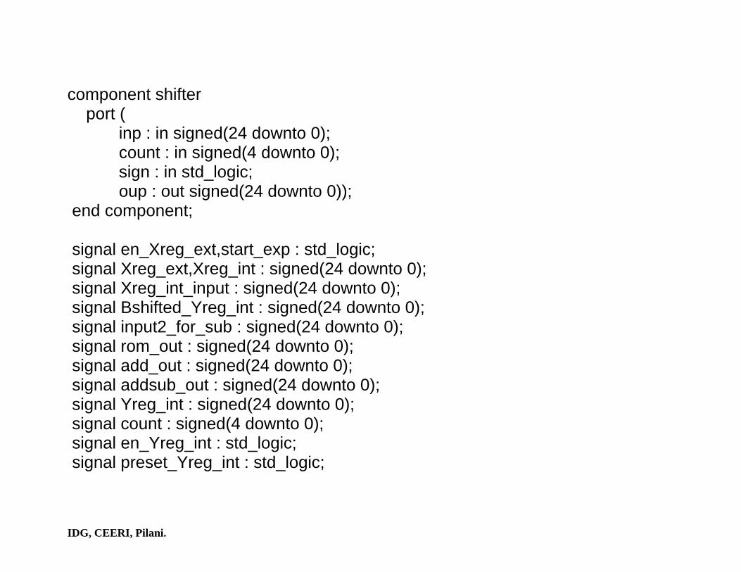
component shifter port ( inp : in signed(24 downto 0); count : in signed(4 downto 0); sign : in std_logic; oup : out signed(24 downto 0)); end component; signal en_Xreg_ext,start_exp : std_logic; signal Xreg_ext,Xreg_int : signed(24 downto 0); signal Xreg_int_input : signed(24 downto 0); signal Bshifted_Yreg_int : signed(24 downto 0); signal input2_for_sub : signed(24 downto 0); signal rom_out : signed(24 downto 0); signal add_out : signed(24 downto 0); signal addsub_out : signed(24 downto 0); signal Yreg_int : signed(24 downto 0); signal count : signed(4 downto 0); signal en_Yreg_int : std_logic; signal preset_Yreg_int : std_logic;

IDG, CEERI, Pilani.
signal en_Xreg_int : std_logic; signal present_state : exp_fsm_state; signal Xreg_int_input_control : std_logic; signal reset_counter : std_logic; signal en_counter : std_logic; signal counter : integer range 0 to 27; begin --------------------------------------------------------- output <= std_logic_vector(Yreg_int); --------------------------------------------------------- start_exp_decode : process(clock) begin if (clock'event and clock = '1') then if (reset = '1') then start_exp <= '0'; elsif (b2fc = "1001") then start_exp <= '1';

IDG, CEERI, Pilani.
else start_exp <= '0'; end if; end if; end process; --------------------------------------------------------- Sexp_decode : process(b2fc) begin if (b2fc = "1001") then en_Xreg_ext <= '1'; else en_Xreg_ext <= '0'; end if; end process; --------------------------------------------------------- PXreg_ext : process(clock) begin if (clock'event and clock = '1') then if ( en_Xreg_ext = '1') then Xreg_ext <= signed(dbus);

IDG, CEERI, Pilani.
end if; end if; end process; ------------------------------------------------------------ PXreg_int : process(clock) begin if (clock'event and clock = '1') then if (en_Xreg_int = '1') then Xreg_int <= Xreg_int_input; end if; end if; end process; ------------------------------------------------------------ Pcounter : process(clock) begin if (clock'event and clock = '1') then if(reset_counter = '1') then counter <= 0;

IDG, CEERI, Pilani.
elsif (en_counter = '1') then counter <= counter + 1; end if; end if; end process; ------------------------------------------------------------ PYreg_int : process(clock) begin if (clock'event and clock = '1') then if(preset_Yreg_int = '1') then Yreg_int <= "0100000000000000000000000"; elsif (en_Yreg_int = '1') then Yreg_int <= addsub_out; end if; end if; end process; ------------------------------------------------------------ PXreg_int_input : process(add_out,Xreg_ext,

IDG, CEERI, Pilani.
Xreg_int_input_control) begin if ( Xreg_int_input_control = '1') then Xreg_int_input <= Xreg_ext; else Xreg_int_input <= add_out; end if; end process; ------------------------------------------------------------ add_out <= Xreg_int - rom_out; ------------------------------------------------------------ -- instance of barrel shifter ------------------------------------------------------------ count <= to_signed(counter,5); b1 : shifter port map ( Yreg_int, count, Yreg_int(24), Bshifted_Yreg_int);

IDG, CEERI, Pilani.
------------------------------------------------------------ Pinput2_for_addsub : process(Bshifted_Yreg_int,Xreg_int, Yreg_int) begin if (Xreg_int(24) = '0') then addsub_out <= Yreg_int + Bshifted_Yreg_int; else addsub_out <= Yreg_int - Bshifted_Yreg_int; end if; end process; ------------------------------------------------------------ Pexp_rom : process(counter, Xreg_int) constant exp_rom : exp_table := (("0010110001011100100001011"), ("0001100111110011001000111"), ("0000111001000111111110111"), ("0000011110001001110000011"), ("0000001111100001010001100"),

IDG, CEERI, Pilani.
("0000000111111000001010011"), ("0000000011111110000001010"), ("0000000001111111100000001"), ("0000000000111111111000000"), ("0000000000011111111110000"), ("0000000000001111111111100"), ("0000000000000111111111111"), ("0000000000000011111111111"), ("0000000000000001111111111"), ("0000000000000000111111111"), ("0000000000000000011111111"), ("0000000000000000001111111"), ("0000000000000000001000000"), ("0000000000000000000100000"), ("0000000000000000000001111"), ("0000000000000000000001000"), ("0000000000000000000000011"), ("0000000000000000000000001"), ("0000000000000000000000000"), ("0000000000000000000000000"),

IDG, CEERI, Pilani.
("0000000000000000000000000"), ("0000000000000000000000000")); constant exp_rom1 : exp_table := (("1101001110100011011110100"), ("1101001110100011011110100"), ("1110110110010110100111100"), ("1111011101110100001110010"), ("1111101111011110100110100"), ("1111110111110111110101001"), ("1111111011111101111110110"), ("1111111101111111011111111"), ("1111111110111111111000000"), ("1111111111011111111110000"), ("1111111111101111111111100"), ("1111111111110111111111111"), ("1111111111111100000000000"), ("1111111111111110000000000"), ("1111111111111111000000000"),

IDG, CEERI, Pilani.
("1111111111111111100000000"), ("1111111111111111110000000"), ("1111111111111111111000000"), ("1111111111111111111100000"), ("1111111111111111111110000"), ("1111111111111111111111000"), ("1111111111111111111111101"), ("1111111111111111111111111"), ("0000000000000000000000000"), ("0000000000000000000000000"), ("0000000000000000000000000"), ("0000000000000000000000000")); begin if (Xreg_int(24) = '0') then rom_out <= exp_rom(counter); else rom_out <= exp_rom1(counter); end if; end process;

IDG, CEERI, Pilani.
------------------------------------------------------------ -- controller for the above exp ------------------------------------------------------------ controls : process ( present_state ) begin case present_state is when st0 => Xreg_int_input_control <= '0'; en_Xreg_int <= '0'; reset_counter <= '1'; en_counter <= '0'; preset_Yreg_int <= '0'; en_Yreg_int <= '0'; when st1 => Xreg_int_input_control <= '1'; en_Xreg_int <= '1';

IDG, CEERI, Pilani.
reset_counter <= '0'; en_counter <= '1'; preset_Yreg_int <= '1'; en_Yreg_int <= '0'; when st2 => Xreg_int_input_control <= '0'; en_Xreg_int <= '1'; reset_counter <= '0'; en_counter <= '1'; preset_Yreg_int <= '0'; en_Yreg_int <= '1'; end case; end process; exp_fsm : process(clock,reset) begin

IDG, CEERI, Pilani.
if (clock'event and clock='1') then if (reset = '1') then present_state <= st0; else case present_state is when st0 => if(start_exp = '0') then present_state <= st0; elsif(start_exp = '1') then present_state <= st1; else present_state <= st0; end if; when st1 => present_state <= st2;

IDG, CEERI, Pilani.
when st2 => if (counter = 25) then present_state <= st0; else present_state <= st2; end if; end case; end if; end if; end process; end rtl_SEXP; ------------------------------------------------------------

IDG, CEERI, Pilani.
Test Bench Writing File Types and File Objects Objects of file types represent files in the host environment. They provide a mechanism by which a VHDL design communicates with the host computer environment. Syntax (of a file type is) : type file-type-name is file of type-name;

IDG, CEERI, Pilani.
Example : type VECTORS is file of BIT_vector; type NAMES is file of STRING;
A file of type VECTORS has a sequence of values of type BIT vector; a file of type NAMES has a sequence of strings as values in it. A file object is declared using a file declaration. Note that these files are binary files. For text files, use TEXTIO package.
Syntax (of a file object is) : file file-name : file-type-name is mode string-expression;

IDG, CEERI, Pilani.
Example : file VEC_FILE : VECTORS is in "/home/rs/asp/div.vec"; file OUTPUT : NAMES is out "stdout"; VEC_FILE is declared to be a file that contains a sequence of BIT vectors and it is an input file. It is associated with the file "/home/rs/asp/div.vec" in the host environment.
Procedures and functions that are implicitly declared for each file type are : procedure READ(F : in file-type-name; VALUE : out type-name); -- Gets the next value in VALUE from file F. procedure WRITE(F : out file-type-name; VALUE : in type-name); -- Appends a given value in VALUE to file F.

IDG, CEERI, Pilani.
function ENDFILE(F : in file-type-name) return BOOLEAN; -- Returns FALSE if a read on an input file F will be successful in getting -- another value, otherwise it returns TRUE. procedure READ (F : in file-type-name; VALUE : out type-name; LENGTH : out NATURAL); -- LENGTH returns the number of elements of the array that was read. A -- file cannot be opened or closed explicitly, and values within a file can --- only be accessed sequentially.

IDG, CEERI, Pilani.
Example : Usage of files. entity FA_TEST is end FA_TEST; architecture IO_EXAMPLE of FA_TEST is component FULL_ADD port(CIN, A, B : in BIT; COUT, SUM : out BIT); end component; subtype STRING3 is BIT_vector(0 to 2); subtype STRING2 is BIT_vector(0 to 1); type IN_TYPE is file of STRING3; type OUT_TYPE is file of STRING2; file VEC_FILE : IN_TYPE is in "/home/rs/asp/fadd.vec"; file RESULT_FILE : OUT_TYPE is out /home/rs/asp/fadd.out";

IDG, CEERI, Pilani.
signal S : STRING3; signal Q : STRING2; begin FA : FULL_ADD port map(S(0), S(1), S(2), Q(0), Q(1)); process constant PROPAGATION_DELAY : TIME := 25 ns; variable IN_STR : STRING3; variable OUT_STR : STRING2; begin while(not ENDFILE(VEC_FILE)) loop READ(VEC_FILE, IN_STR);
IDG, CEERI, Pilani.
S <= IN_STR; wait for PROPOGATION_DELAY; OUT_STR := Q; WRITE(RESULT_FILE, OUT_STR); end loop; assert FALSE report "Completed"; end process; end IO_EXAMPLE;

IDG, CEERI, Pilani.
Text File Usage The pre-defined TEXTIO package contains procedures and functions that provide a means for reading and writing text files. Thus, text files containing vectors (perhaps generated manually or by another program) can be used to drive simulations. Similarly, the simulation outputs being monitored can be written onto text files for manual examination or use by another tool. Examples: use STD.TEXTIO.all; This clause makes all the procedures and functions for text input/output contained in package TEXTIO analysed in library STD visible in the following design unit.

IDG, CEERI, Pilani.
file VECTORS : TEXT is in "/home/rs/vec.txt"; Open file "/home/rs/vec.txt" as file object named VECTORS of file type TEXT in input mode. Type TEXT is a pre-declared type in package TEXTIO whose declaration is as follows : type TEXT is file of STRING; The process in which the file is read may look as follows : process(CLOCK) variable BUF : LINE; -- LINE is pre-declared type in package TEXTIO whose declaration is as follows :

IDG, CEERI, Pilani.
-- type LINE is access STRING; -- Thus, type LINE is an access type (pointer) which points to a STRING. variable N1_VAR : BIT_vector(0 to 3); variable N2_VAR : integer; begin if ((CLOCK'event and CLOCK = '1') and (not ENDFILE(VECTORS)) then READLINE(VECTORS, BUF); -- READ() is an overloaded procedure READ(BUF, N1_VAR); READ(BUF, N2_VAR);

IDG, CEERI, Pilani.
-- apply values read to input signals of entity under test
N1 <= N1_VAR; N2 <= N2_VAR; elsif (ENDFILE(VECTORS)) then report "Finished All the Vectors"; end if; end process;

IDG, CEERI, Pilani.
Test Bench To test the VHDL model of any digital hardware we need to apply test stimuli waveforms to its inputs, capture the response waveforms at the model's outputs and compare the captured response waveforms with the expected output waveforms. A VHDL model written for the above purpose essentially simulates the running of a test on a hardware test setup with the Device Under Test (DUT) plugged in the DUT socket - and is typically called a test bench.
IDG, CEERI, Pilani.
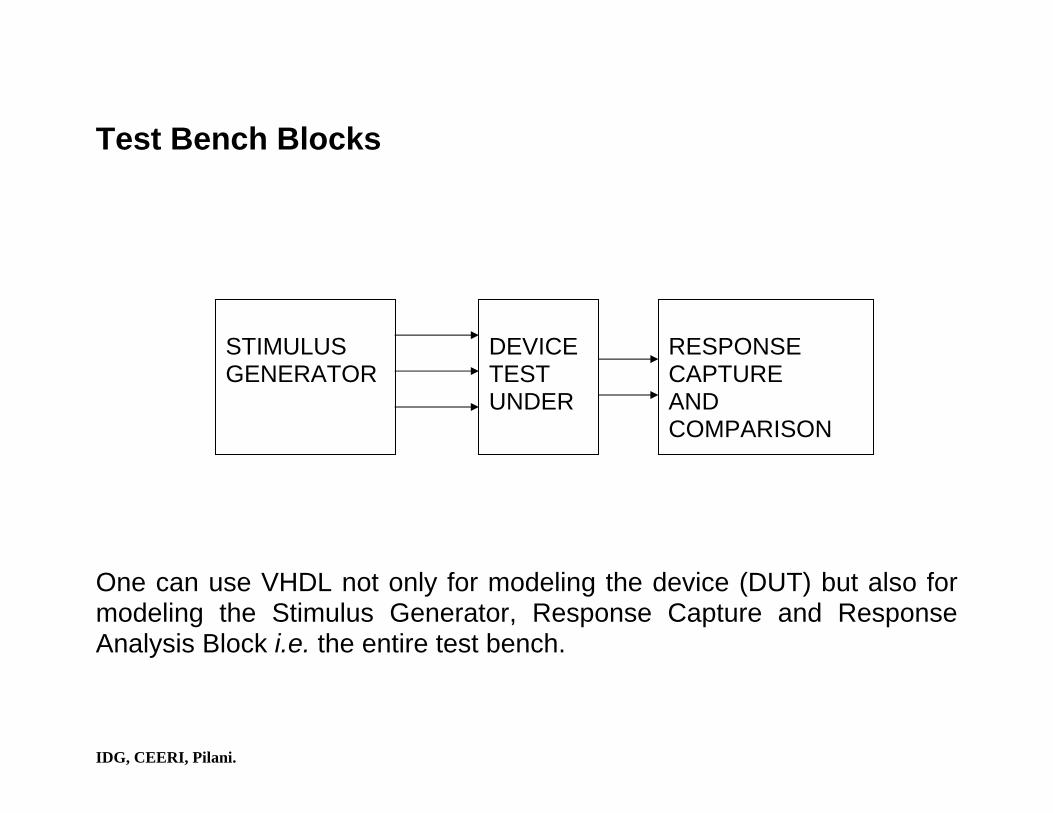
Test Bench Blocks One can use VHDL not only for modeling the device (DUT) but also for modeling the Stimulus Generator, Response Capture and Response Analysis Block i.e. the entire test bench.
STIMULUS GENERATOR
DEVICE TEST UNDER
RESPONSE CAPTURE AND COMPARISON

IDG, CEERI, Pilani.
Example : A typical test bench template. entity TEST_BENCH is end TEST_BENCH; architecture ILLUSTRATIVE of TEST_BENCH is -- declare DUT in a component declaration. -- declare local signals that will connect to the -- DUT's I/O's. begin -- Include a process that will generate the stimulus waveforms on signals -- that will connect to the DUT's inputs. Instantiate the DUT such that -- these signals connects to the DUT's inputs. Include a process that will -- monitor and compare the captured response waveforms from the
IDG, CEERI, Pilani.
-- DUT's outputs by having all the local signals that connect to the DUT's -- outputs on its sensitivity list. end ILLUSTRATIVE;

IDG, CEERI, Pilani.
library IEEE; use IEEE.STD_LOGIC_1164.ALL; use ieee.std_logic_arith.all; use std.textio.all; entity testbench is end; architecture structure of testbench is component SEXP port(Dbus : in std_logic_vector(24 downto 0); clock, reset : in std_logic; b2fc : in std_logic_vector(3 downto 0); output : out std_logic_vector(24 downto 0)); end component; signal data_in,output:std_logic_vector(24 downto 0); signal clock,rst:std_logic:='0'; signal b2fc : std_logic_vector(3 downto 0);

IDG, CEERI, Pilani.
file in_file : text open read_mode is "C:\ravi\test_tb_exp\input.binary"; file out_file : text open write_mode is "C:\ravi\test_tb_exp\parameter.out"; begin processor1: SEXP port map(data_in,clock,rst,b2fc,output); process variable rline : line:=null; variable in1_v: string(1 to 25); variable wline : line:=null; variable out_v:std_logic_vector(24 downto 0); begin wait until clock'event and clock='1'; while not endfile (in_file) loop

IDG, CEERI, Pilani.
b2bc <= "1001"; readline (in_file, rline); --reading data from the file. read (rline,in1_v); data_in<=TO_STDLOGICVECTOR(in1_v); for i in 0 to 27 loop wait until clock'event and clock='1'; end loop; out_v:=output; -- writing output data into the file. write (wline,TO_STRING(out_v)); writeline (out_file,wline); end process; clock<=not clock after 20 ns; rst<='1' after 10 ns, '0' after 15 ns; end structure;