Embed Size (px)
Citation preview
1
PRESENTED BY:PRIYANK GUPTA
04/02 /2012
Generic Low Latency NoC Router Architecture for FPGA Computing Systems
&A Complete Network on Chip Emulation Framework

2
Introduction
Moore’s law is pushing towards more complex SoCsNetwork on Chip one of the technologies which
enable us to keep up with the law.Designing and evaluation of NoC has been a
challenge Complexity of design Inaccurate network/component models Simulation/CAD tools
FPGA provides a platform where above concerns can be addressed and real life data can be measured.
Present on-chip FPGA resources can be used as underlying interconnect fabric

3
NoC Fundamentals
Block diagram of a router.

4
NoC Fundamentals
5
Router Architecture
Simplified block diagram of a router. Flits arriving over the input channels are stored in buffers associated with each input. A set of allocators assigns buffers on the next node and channel bandwidth to pending flits. When a flit has been allocated the resources it needs, it is forwarded by the crossbar switch to an output channel.

6
Crossbar Example
A 4×5 crossbar switch as implemented with 5 4:1 multiplexers. Each multiplexer selects the input to be connected to the corresponding output.

7
Crossbar Symbol

8
Data Packet Example
Packet format for our simple network. Time, in cycles, is shown in the vertical direction, while the 18 signals of a channel are shown in the horizontal direction. The leftmost signals contain the phit type, while the 16 remaining signals contain either a destination address or data, or are unused in the case of a null phit.
9
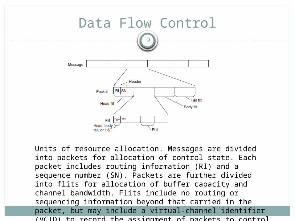
Data Flow Control
Units of resource allocation. Messages are divided into packets for allocation of control state. Each packet includes routing information (RI) and a sequence number (SN). Packets are further divided into flits for allocation of buffer capacity and channel bandwidth. Flits include no routing or sequencing information beyond that carried in the packet, but may include a virtual-channel identifier (VCID) to record the assignment of packets to control state.

10
Data Flow Algorithms
Deterministic: Algorithm always chooses the same path between x and y even if multiple options exist
Simple to implement Poor job of balancing load
Oblivious: Algorithm decides on a path between x and y without any information on the network’s prior state. Deterministic is a subset.
Adaptive: Algorithm adapts to the state of the network. Information includes node status, channel load information, queue length etc.

11
Routing Mechanics
Mechanism used to implement any routing algorithm
Table based Routing: The set of paths for each pair of nodes is stored in the table, and the table is indexed by the source and destination node. Only that portion of the table that is needed on a particular node need be stored on that node.
Algorithmic Routing: Routing relation is computed using a network specific algorithm. More efficient in terms of both area and speed.

12
Flow Control
Determines how network resources such as channel bandwidth, buffer capacity and control state are allocated to the data traversing.
Bufferless Flow Control Simple to implement Packets are dropped or misrouted if resource is not
available
Buffered Flow Control Temporarily store packets in a buffer therefore less
probability of dropped packets Additional cost of hardware for implementation
13
Network Topologies
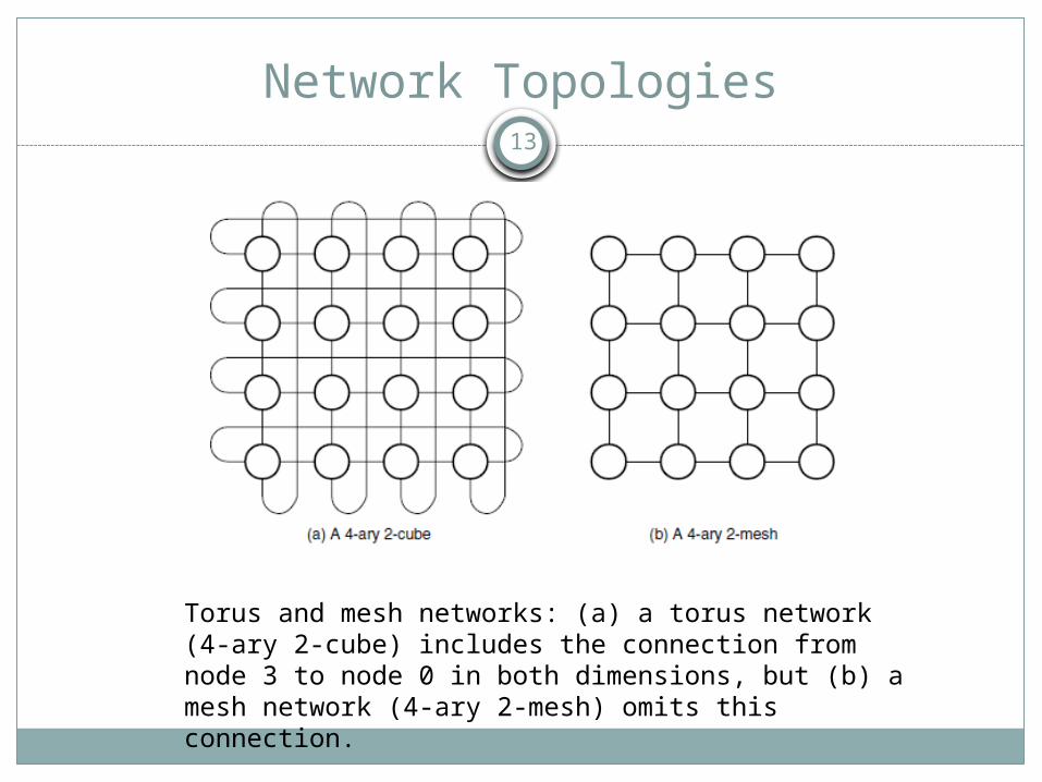
Torus and mesh networks: (a) a torus network (4-ary 2-cube) includes the connection from node 3 to node 0 in both dimensions, but (b) a mesh network (4-ary 2-mesh) omits this connection.

14
FPGA Emulation Framework
Emulation environment developed to explore, evaluate and compare a variety of NoC solutions.
Current FPGA implementations are limited in flexibility and do not allow full test of NoC implementations
Cycle accurate simulations using a combination of hardware and software modules.
Added flexibility due to modular approach of architecture.
16000 times faster than HDL simulator
15
NoC Emulation Architecture

16
NoC Emulation Architecture
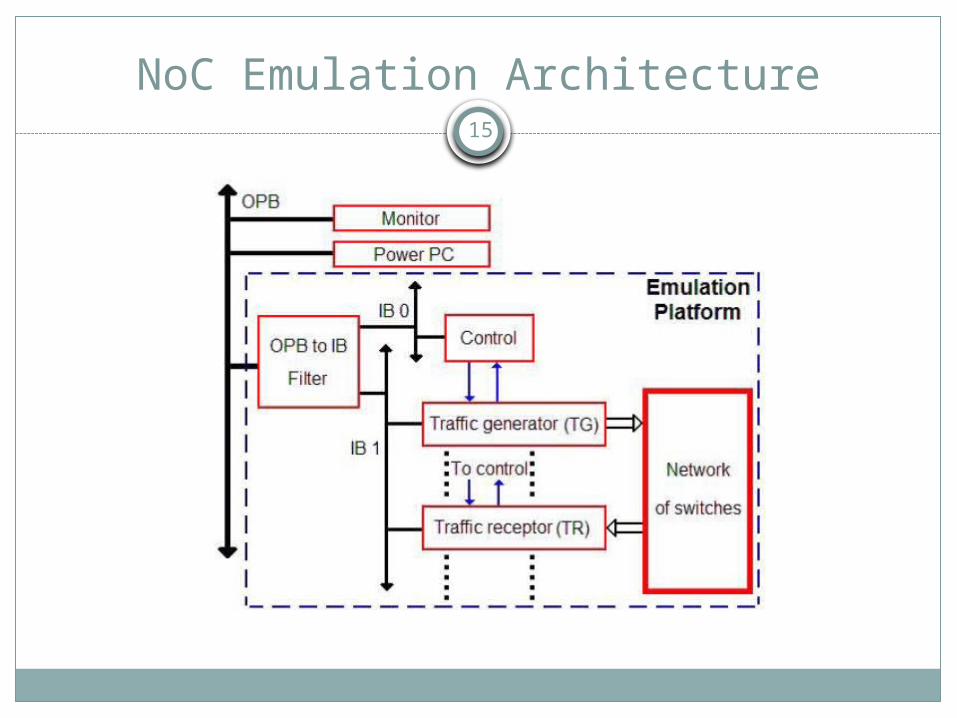
Xilinx Virtex 2 Pro V20 with an embedded power PC: Processor is povides the much needed flexibility for the emulation proces.
Monitor Module: Responsible for the interface between the host PC and FPGA board. Also streams out data generated from various tests.
Programmable NoC Platform: Responsible for traffic generators and receptors. Also keeps the user defined interconnection set between switches and network.

17
Data Flow
Above Traffic Generator (TG) can provide an image of the congestion of the network at each moment in time of the emulation.
Each time a flit is not acknowledged by its receptor (i.e. switch or TR) andhas to be resent, a readable counter by the processor is incremented.

18
NoC Emulation Flow
19
NoC Emulation Flow
No re synthesizing or re mapping of system due to HW-SW structure
Processor is able to initialize parameters in hardware
Emulation flow is categorized as: Stochastic Emulation Flow: Implemented at the hardware
level only. Configuration is implemented at the compilation level
Trace-based Emulation Flow: Entire NoC trace is loaded via software located on RAM. Processor streams the data into the emulated NoC and collects information on latency and congestion.

20
Results – Run Time
The total delivery time with the same amount of packets for the burst-mode is higher than for the uniform traffic. This is because the probability of collisionsbetween packets in the burst-mode is significantly higher.

21
Results – Congestion Rate
Plots indicate that the congestion rate does not increase linearly with the number of delivered packets in a burst mode.

22
Results – Avg. Latency
The average latency of packets reaches a limit of congestion, which is the limit ofthe NoC in terms of latency

23
Generic Low Latency Router - Motivation
New Generation of FPGAs comprise of millions of LUTs and will contain many parallel soft processor cores and glue/extra logic.
Use of traditional interconnect schemes will lead to under utilization.
Future designs are perceived to be at a higher level than traditional gate level. Functionality will be implemented through programmability of such cores.
Increased complexity of FPGA will lead to inefficient RTL based design flow.

24
Proposed Solution
Network on Chip can provide a flexible, scalable and reliable communication solution for such large and complex solutions.
NoC provides the ability to change bandwidth and add processing elements. Cost is linear in this case whereas, traditional cross bar interconnects scale exponentially.
FPGA contains significant global and local routing resources which can be used to construct the interconnect fabric and implement routing algorithm.
25
Prior Work
Many routers have been designed for NoC FPGA implementation
Circuit switch router: Head flit charts out the path, body follows. It has long circuit setup latency and low bandwidth utilization but once path is setup, Q0S is guaranteed and data latency is less.
Time multiplexed router: Precomputed communication pattern. Less flexible. Works well when communication loads are 100% but performance drops significantly when load < 40%
Packet switch router: Negotiate network resources dynamically at run time. Flexible and scalable and low resource utilization but have high latency (about 8 clock cycles per hop).
FPGAs primarily used for prototyping and evaluating latency, throughput, cost and power.
26
Generic Low Latency NoC Router - Overview
Reconfigurable wormhole router for packet-switched NoC designs
Low routing latency, low complexity and high buffer utilization
Designed to be scalable, flexible and reliable for a variety of FPGA platforms and network configurations.
1-D ring, 2-D mesh and 3-D cube network topologies were used to measure the feasibility of design and implementation on the FPGA.
2 Cycles per hop latency

27
Wormhole Router Block Diagram
Three main components: flow control, components and pipeline control
Wormhole flow controlComponents include input
and output ports, arbiter to arbitrate between multiple requests and FSM to maintain state of output port
Pipeline control is instrumental in achieving low latency per hop and parallel computation

28
Wormhole Flow Control
(a) the header arrives at the node, while the virtual channel is in the idle state (I) and the desired upper (U) output channel is busy — allocated to the lower (L) input.
(b) the header is buffered and the virtualchannel is in the waiting state (W), while the first body flit arrives.

29
Wormhole Flow Control
(c) the header and first body flit are buffered, while the virtual channel is still in the waiting state. In this state, the input channel is blocked. The second body flit cannot be transmitted, since it cannot acquire a flit buffer.
(d) the output virtual channel becomes available and allocated to this packet. The state moves to active (A) and the head is transmitted to the next node.

30
Wormhole Flow Control
(e) The body flits follow
(f) The body flits follow

31
Wormhole Flow Control
(g) the tail flit is transmitted and frees the virtual channel, returning it to the idle state.
(h) a time-space diagram showing this process.
32
Packet Format
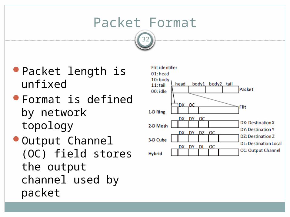
Packet length is unfixed
Format is defined by network topology
Output Channel (OC) field stores the output channel used by packet
33
Input Port
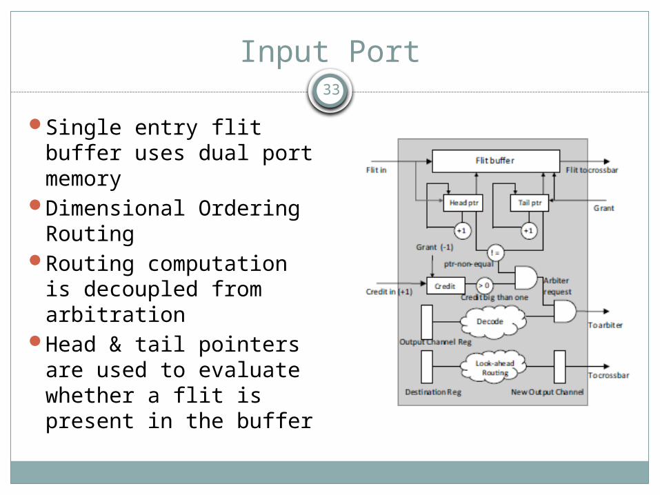
Single entry flit buffer uses dual port memory
Dimensional Ordering Routing
Routing computation is decoupled from arbitration
Head & tail pointers are used to evaluate whether a flit is present in the buffer
34
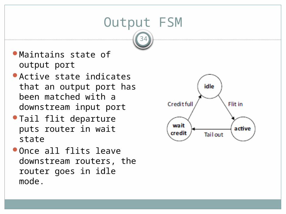
Output FSM
Maintains state of output port
Active state indicates that an output port has been matched with a downstream input port
Tail flit departure puts router in wait state
Once all flits leave downstream routers, the router goes in idle mode.

35
Router Pipeline Organization
a. Clock 1: Destination address and output channel latched in. Flit is written in flit buffer. During this period, arbitration result and look ahead routing is computed.
b. Clock 2: Crossbar control signal latched in and flit is read from the granted port.

36
Timing of Second Pipeline Stage
T = Tco + Tlut + Trot + Tsu
• Tco is clock to register (or memory) output delay
• Tlut is the delay of LUT cells (multiplexer logic)
• Trot is the delay due to programmable wire routing
• Tsu isthe setup time of the device

37
Pipeline Diagram ASIC vs FPGA Router

38
Network Topologies Used
39
Credit Based Routing
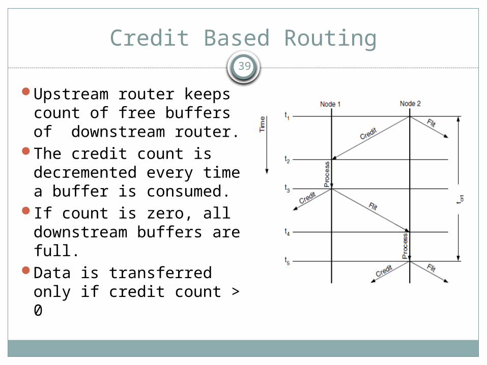
Upstream router keeps count of free buffers of downstream router.
The credit count is decremented every time a buffer is consumed.
If count is zero, all downstream buffers are full.
Data is transferred only if credit count > 0
40
Results – Resource Utilization
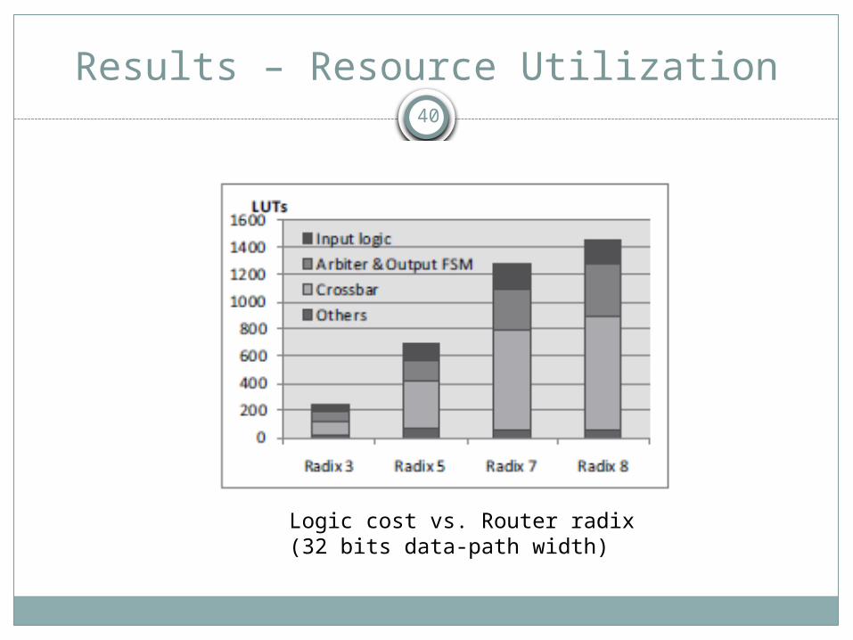
Logic cost vs. Router radix(32 bits data-path width)

41
Results – Resource Utilization
logic cost vs. Data-path width

42
Results - Timing
(a)Maximum clock rate vs. Router radix(b) two important critical paths within a router
43
Results - Power
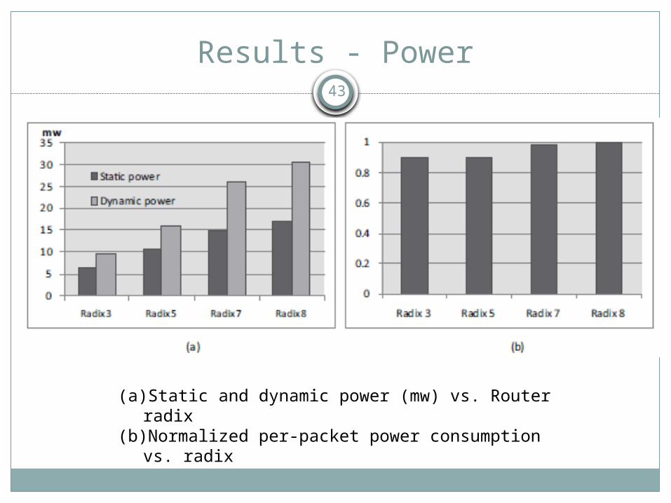
(a)Static and dynamic power (mw) vs. Router radix(b)Normalized per-packet power consumption vs.
radix

44
Packet Generator and Receiver
Due to pin limitations, packets must be generated using on chip logic within the FPGA rather than external sources. Each node of the NoC system is attached with a packet generator and receiver.

45
Results – Resource Utilization per Configuration
Resource utilization of different network configurations
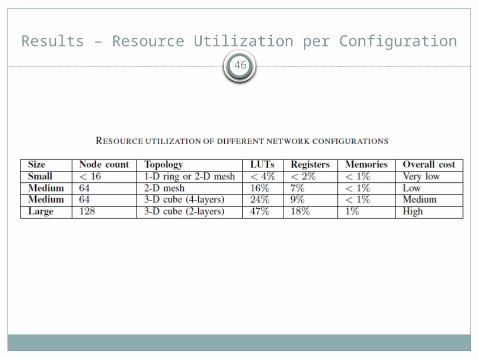
46
Results – Resource Utilization per Configuration

47
Summary
Highly scalable router which is easily used among different network topologies.
Low hop by hop propagation delay using a packet switch NoC router.
Analysis of router in terms of scalability, hardware cost, operation speed and power dissipation.
Real world feasibility of such router architecture has been demonstrated and its usage within FPGA platform provides a very robust and cost effective solution.