Embed Size (px)
Citation preview

Solvent recovery
February 2016

2
Solvent recovery

3
from liquid stream: Distillation
In many pharmaceutical, chemical and textile processes, solvents areused as solvent mixtures or as water solutions. Solvents can (“must”)be recovered.
TMIP manufactures both batch and continuous distillation plantssuitable for the above mentioned process. Discontinuous (batch) unitsare normally used for recovering solvents from complex mixtures,usually present in pharmaceutical industry.
Continuous distillers are aimed at chemical industries.
TMIP distillation plants include units for operating under pressure orvacuum, double or triple effect, with yields above 95% and controlledby some of the most sophisticated control systems available.

4
Distillation
Typical recovered compounds:

5
Distillation
The distillation process cannot always be optimized in a theoretical way. In some cases the presence of substances deriving from the proprietary production process that generated the pollutant wastes can hinder and/or limit distillation.
Process Solution
Continuous Distillation
Batch Distillation
Azeotropic Distillation
Extractive Distillation
Vacuum Distillation
High pressure Distillation
With Mechanical Compression
With Thermocompression
Multiple effects
TMIP offers its distillation experience in order to recover the solvents into the original process or other process.

6
Ethanol –water
Process Data
• Operation:
Continuous Double Effects
• Type: Sieve Trays
• Capacity: 3000 kg/h
• Operating pressure: Atm
• Top operating Temperature:
78 °C
• Bottom operating Temperature:
100 °C
• Recovered Ethanol: >98%
• Concentration of Recovered
Ethanol: >95% wt.
• Material of construction:
AISI 304 SS
7
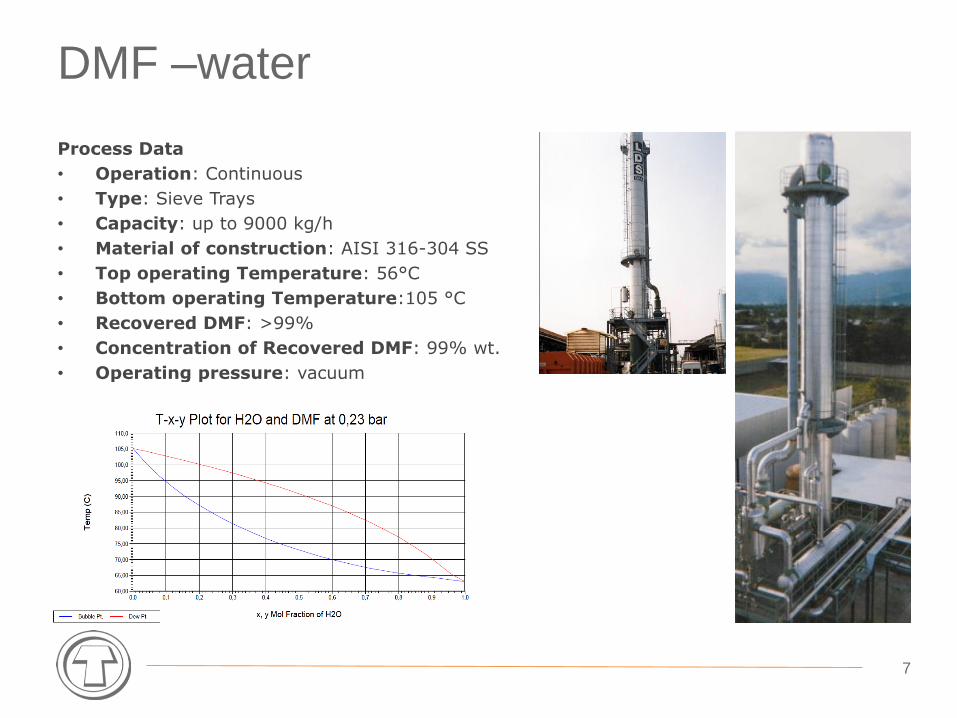
DMF –water
Process Data
• Operation: Continuous
• Type: Sieve Trays
• Capacity: up to 9000 kg/h
• Material of construction: AISI 316-304 SS
• Top operating Temperature: 56°C
• Bottom operating Temperature:105 °C
• Recovered DMF: >99%
• Concentration of Recovered DMF: 99% wt.
• Operating pressure: vacuum

8
MC / ACETONE / IPA / TEA-DEA
MC -water IPA -water TEA/DEA –water ACETONE -water
Operation Continuous Continuous Batch Continuous/Batch
Type Sieve Trays Sieve Trays Structured Packing
Structured Packing
Capacity 1500 kg/h 1500 kg/h 800 kg/h 1500 kg/h
Operating pressure
Atm. Atm. Atm. Atm.
Concentrationof Recovered Compounds
99% wt 85% wt 99% wt 95% wt99% wt
Material of construction
AISI 316 SS AISI 316 SS Carbon steel, Glass linedColumn,
Titanium heat exchanger
AISI 316 SS

9
IPA –water
Process Data
• Operation: Continuous double effects
• Type: Sieve Trays
• Capacity: 5000 kg/h
• IPA inlet concentration: 50% wt
• Top operating Temperature: 80°C
• Bottom operating Temperature:100 °C
• Recovered IPA: >98%
• Concentration of Recovered IPA: >87% wt.
• Operating pressure: atm
• Material of construction: AISI 316 SS / HastelloyC22

10
Ethyl acetate –water
Process Data
• Operation: Continuous
• Type: Sieve Trays
• Capacity: 1000 kg/h
• EtAcinlet concentration: 50% wt
• Top operating Temperature: 70°C
• Bottom operating Temperature:100 °C
• Concentration of Recovered EtAc: >99% wt.
• Operating pressure: atm
• Material of construction: AISI 304 SS

11
from gaseous stream: Absorption

12
DMF, NMP is highly soluble in water; TM.I.P.exploits this characteristic of the soluble watersolvent that can be recovered by washing the airin counter current air stream with water in a platestower. Solvent is collected on the bottom of thetower in solution with water. The solution will bedistilled to recover pure solvent.
Absorption: solvent recovery

13
Pollutants removal takes place through a “washing” processby means of liquid. Particles with diameter > 1 μm thatimpact water droplets or wet surface generates theabsorption process. A liquid detains small particles byabsorption that is the selective passage of one or moregaseous components into liquid phase.
The liquid incorporating the pollutants is then recovered onthe bottom of the washing tower and treated.
Absorption: pollutant removal

15
from gaseous stream: Adsorption
It’s adopted for treating exhaust gas recoveringpollutants with the possibility of recycling them in anew process.
Adsorbing materials are micro porous substanceswith a huge surface/height (up to 1700 m2/gr) suchas activated carbons, synthetic zeolite, silica gel andactivated alumina.
TMIP designs & manufactures adsorption plants withpollutant removal levels of 97% and with aparticularly fast investment payback.

16
Adsorption
Process Solution:
• Activated Carbon regeneration by steam
• Activated Carbon regeneration by hot nitrogen
• with Thermocompression for steam saving
• With Distillation Units

17
Hexane recovery
Process Data
• Operation: Continuous
• Type: Steam regeneration
• Capacity: 200.000 Nm3/h
• Number of adsorbers: 5
• Solvent inlet concentration: 5 g/Nm3
• Recovery percentage: >96%
• Steam specific
consumption: 3.5 kgsteam/kgsolvent

18
Toluene recovery
Process Data
• Operation: Continuous
• Type: Steam regeneration
• Capacity: 200.000 Nm3/h
• Number of adsorbers: 5
• Solvent inlet concentration: 5 g/Nm3
• Recovery percentage: >96%
• Steam specific
consumption: 3.5 kgsteam/kgsolvent

19
Ethyl acetate recovery
Process Data
• Operation: Continuous
• Type: Steam regeneration and Ethyl acetate water mixer distillation
• Capacity: 80.000 Nm3/h
• Number of adsorbers: 3
• Solvent inlet concentration: 8 g/Nm3
• Recovery percentage: >96%
• Steam specific
consumption: 3 kgsteam/kgsolvent

20
Vapour Recovery Unit
The main advantages for recovering vapours are:
• Reduce emission of environmentally hazardous compounds;
• Increase safety and reduce health risks linked with the distribution net of gasoline or crude oil;
• Recovery of valuable energy resources;
• VRU capacity: from 150 to 3500 m3/h of vapours.
Main application of VRU:
Storage terminals;
Truck and rail car loading;
Marine loading system;
Vapour balance systems.

21
All emission regulations can be achieved:
TA-Luft: 150 mg/m3
EU Directive: 35 g/m3
US EPA: 5 mg/l loaded
Our VRU may even coupled with a second stage plant, reducing emissions to as low as 50 mg/m3.
Process consists of three main steps:
Adsorption of the VOC on activated carbon bed;
Regeneration of the carbon by means of vacuum;
Re-absorption and recovery of VOC by absorbent liquid.
Vapour Recovery Unit
22
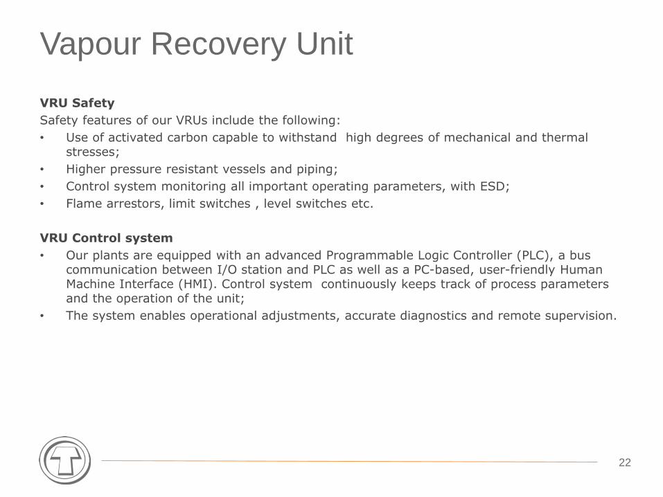
Vapour Recovery Unit
VRU Safety
Safety features of our VRUs include the following:
• Use of activated carbon capable to withstand high degrees of mechanical and thermal stresses;
• Higher pressure resistant vessels and piping;
• Control system monitoring all important operating parameters, with ESD;
• Flame arrestors, limit switches , level switches etc.
VRU Control system
• Our plants are equipped with an advanced Programmable Logic Controller (PLC), a bus communication between I/O station and PLC as well as a PC-based, user-friendly Human Machine Interface (HMI). Control system continuously keeps track of process parameters and the operation of the unit;
• The system enables operational adjustments, accurate diagnostics and remote supervision.

TM.I.P. S.r.l. - Termomeccanica Industrial Process
Via Fossamastra 22- 19126
La Spezia – Italy
Tel. +39 0187 513.410 - Fax. +39 0187 515.352
www.tmip.termomeccanica.com
thank you


![Compresor Gas Vru 7CDL 37-1-614[1]](https://img.pdfslide.us/doc/110x75/577cc5551a28aba7119c0e42/compresor-gas-vru-7cdl-37-1-6141.jpg)