Embed Size (px)
Citation preview
AFRL-RY-WP-TP-2009-1306
A MODULATION BASED APPROACH TO WIDEBAND-STAP (BRIEFING CHARTS) Ke Yong Li, Unnikrishna S. Pillai, Peter Zulch, and Michael Callahan C & P Technologies, Inc. OCTOBER 2007
Approved for public release; distribution unlimited.
See additional restrictions described on inside pages
STINFO COPY
AIR FORCE RESEARCH LABORATORY SENSORS DIRECTORATE
WRIGHT-PATTERSON AIR FORCE BASE, OH 45433-7320 AIR FORCE MATERIEL COMMAND
UNITED STATES AIR FORCE

i
REPORT DOCUMENTATION PAGE Form Approved OMB No. 0704-0188
The public reporting burden for this collection of information is estimated to average 1 hour per response, including the time for reviewing instructions, searching existing data sources, gathering and maintaining the data needed, and completing and reviewing the collection of information. Send comments regarding this burden estimate or any other aspect of this collection of information, including suggestions for reducing this burden, to Department of Defense, Washington Headquarters Services, Directorate for Information Operations and Reports (0704-0188), 1215 Jefferson Davis Highway, Suite 1204, Arlington, VA 22202-4302. Respondents should be aware that notwithstanding any other provision of law, no person shall be subject to any penalty for failing to comply with a collection of information if it does not display a currently valid OMB control number. PLEASE DO NOT RETURN YOUR FORM TO THE ABOVE ADDRESS.
1. REPORT DATE (DD-MM-YY) 2. REPORT TYPE 3. DATES COVERED (From - To) October 2007 Conference Briefing Charts 25 May 2006 – 19 October 2007
4. TITLE AND SUBTITLE A MODULATION BASED APPROACH TO WIDEBAND-STAP (BRIEFING CHARTS)
5a. CONTRACT NUMBER FA8750-06-C-0117
5b. GRANT NUMBER
5c. PROGRAM ELEMENT NUMBER 62204F
6. AUTHOR(S)
Ke Yong Li (C & P Technologies, Inc.) Unnikrishna S. Pillai (Polytechnic University) Peter Zulch (AFRL/RIEC) Michael Callahan (AFRL/RYRT)
5d. PROJECT NUMBER
5017 5e. TASK NUMBER
RL 5f. WORK UNIT NUMBER
517R1511 7. PERFORMING ORGANIZATION NAME(S) AND ADDRESS(ES) 8. PERFORMING ORGANIZATION C & P Technologies, Inc. 317 Harrington Avenue Suites 9 & 10 Closter, NJ 07624-1911 ------------------------------ Polytechnic University Brooklyn, NY 11201
Communications Exploitation Branch (AFRL/RIEC) Information and Intelligence Exploitation Division Air Force Research Laboratory 525 Brooks Road, Rome, NY 13441-4505 United States Air Force -------------------------------------------------------------------------------------- Radar Signal Processing Branch (AFRL/RYRT) RF Sensor Technology Division Air Force Research Laboratory, Sensors Directorate Wright-Patterson Air Force Base, OH 45433-7320 Air Force Materiel Command, United States Air Force
REPORT NUMBER
9. SPONSORING/MONITORING AGENCY NAME(S) AND ADDRESS(ES)
Air Force Research Laboratory
10. SPONSORING/MONITORING AGENCY ACRONYM(S)
Sensors Directorate Wright-Patterson Air Force Base, OH 45433-7320 Air Force Materiel Command United States Air Force
AFRL/RYRT 11. SPONSORING/MONITORING AGENCY REPORT NUMBER(S) AFRL-RY-WP-TP-2009-1306
12. DISTRIBUTION/AVAILABILITY STATEMENT Approved for public release; distribution unlimited.
13. SUPPLEMENTARY NOTES Conference presentation published in the Proceedings of the 41st Annual Asilomar Conference on Signals, Systems, and Computers, held November 04 - 07, 2007 at the Asilomar Hotel and Conference Grounds, Pacific Grove, CA. PAO Case Number: WPAFB 07-0332; Clearance date: 05 Nov 2007. Briefing contains color. See also, AFRL-RY-WP-TP-2009-1307 for a preprint version of the paper based on the briefing, and AFRL-RY-WP-TP-2009-1308 for a postprint version. The U.S. Government is joint author of this work and has the right to use, modify, reproduce, release, perform, display, or disclose the work. Paper contains color.
14. ABSTRACT In this presentation, a new method for processing wideband radar data is presented. To perform the full degree of freedom wideband processing, 3-D space-time adaptive processing (STAP) needs to be implemented, which involves intense computational burden. One approach in this case is to do subband STAP processing and combine these outputs. In this presentation, instead of traditional subband processing, the incoming wide band data signal is modulated by multiple carriers, combined, and filtered prior to processing using narrowband STAP. This method offers a significant decrease in computation burden compared to the subband method.
15. SUBJECT TERMS wideband space-time adaptive processing
16. SECURITY CLASSIFICATION OF: 17. LIMITATION OF ABSTRACT:
SAR
18. NUMBER OF PAGES
30
19a. NAME OF RESPONSIBLE PERSON (Monitor) a. REPORT Unclassified
b. ABSTRACT Unclassified
c. THIS PAGE Unclassified
Michael J. Callahan 19b. TELEPHONE NUMBER (Include Area Code)
N/A Standard Form 298 (Rev. 8-98)
Prescribed by ANSI Std. Z39-18
Ke Yong Li Ke Yong Li C & P Technologies, Inc., Closter, NJC & P Technologies, Inc., Closter, NJ
Unnikrishna Pillai Unnikrishna Pillai Polytechnic University, Brooklyn, NYPolytechnic University, Brooklyn, NY
P t Z l hP t Z l hPeter Zulch Peter Zulch AFRL, Rome, NYAFRL, Rome, NY
Michael CallahanMichael Callahan
2007 ASILOMAR Conference, Pacific Grove, CA. 1
Michael Callahan Michael Callahan AFRL, WrightAFRL, Wright--Patterson AFB, OHPatterson AFB, OH

OutlineOutline
•• Wideband Array Data ModelingWideband Array Data Modeling
•• Optimum Wideband ProcessorOptimum Wideband Processor
•• Subband ProcessingSubband Processing
•• New Approach:New Approach: Subband CombiningSubband Combining•• New Approach: New Approach: Subband Combining Subband Combining without Partitioningwithout Partitioning
•• ConclusionsConclusions
2007 ASILOMAR Conference, Pacific Grove, CA. 2

TimeTime--Domain Wideband Clutter GenerationDomain Wideband Clutter Generation
••Wideband signal is transmitted from all sensorsWideband signal is transmitted from all sensors
••Delay taps are used at sensors to focus the transmitted Delay taps are used at sensors to focus the transmitted ( )s t
signal to a specific look angle signal to a specific look angle o
( , )f t ( ) :f t combined signal at anglecombined signal at angle( , ) :f t combined signal at angle combined signal at angle
Combined signal at desired angle : Combined signal at desired angle : o
o ( , )of t N s t
The combined signal at theThe combined signal at the 2 1N
( )s tsin( )ods tc
( 1) sin( )oN ds tc
d
The combined signal at the The combined signal at the desired look angle has desired look angle has been coherently amplified been coherently amplified
2007 ASILOMAR Conference, Pacific Grove, CA. 3
by a factor of .by a factor of .N

TimeTime--Domain Wideband Clutter GenerationDomain Wideband Clutter Generation••For any other angle the signals from different sensors willFor any other angle the signals from different sensors willFor any other angle, the signals from different sensors will For any other angle, the signals from different sensors will
add up incoherently resulting in a transmit array gain patternadd up incoherently resulting in a transmit array gain pattern
Combined signal at an arbitrar angle is gi en bCombined signal at an arbitrar angle is gi en b••Combined signal at an arbitrary angle is given by:Combined signal at an arbitrary angle is given by:
sin sin( , ) ( 1) .
Nod
f t s t n
1
( , ) ( )n
fc
••BandwidthBandwidth••Center frequencyCenter frequency
80BW MHz435f MH••Center frequency Center frequency
••Number of sensorsNumber of sensors••Interelement spacing Interelement spacing
435cf MHz14N 0.33d m
••Look angle Look angle ••PRF = 625 HzPRF = 625 Hz
0oo
Mountain Top RadarMountain Top Radar
2007 ASILOMAR Conference, Pacific Grove, CA. 4
Mountain Top Radar Mountain Top Radar Parameters are usedParameters are used

Frequency Sensitive Array Gain PatternFrequency Sensitive Array Gain PatternArray Gain PatternArray Gain PatternArray Amplitude PatternArray Amplitude Pattern
2 ( 1)sin( , ) ,k
dN j i
kC e
2( , ) ( , )k kG C
Array Gain PatternArray Gain Patterny py p
1i
2007 ASILOMAR Conference, Pacific Grove, CA. 5
Bandwidth = 395 MHz Bandwidth = 395 MHz -- 475 MHz (80 MHz), Sensors used: 14475 MHz (80 MHz), Sensors used: 14

Array Gain Pattern (Freq. Domain)Array Gain Pattern (Freq. Domain)
A i tt f ti fA i tt f ti f Array gain pattern as function ofArray gain pattern as function ofArray gain pattern as function of Array gain pattern as function of frequency for different anglesfrequency for different angles
Array gain pattern as function of Array gain pattern as function of angle for different frequenciesangle for different frequencies
2007 ASILOMAR Conference, Pacific Grove, CA. 6

TimeTime--Domain Wideband Clutter GenerationDomain Wideband Clutter Generation••The received signal vector arrivingThe received signal vector arrivingThe received signal vector arriving The received signal vector arriving
from for all the sensors is given from for all the sensors is given
bbi
sin id by:by:( , )
( )if t
f t
sin ii
dc
Look di ti( , )
( , )
( ( 1) , )
i ii i
i i
f tr t
f t N
oi direction
Clutter Clutter scatterscatter
••Wideband data vector received Wideband data vector received
( ( ) , )i if i
scatter scatter returnreturn
from all the azimuth angles is:from all the azimuth angles is:
( ) ( )x t r t 2007 ASILOMAR Conference, Pacific Grove, CA. 7
( ) ( , )ii
x t r t

Wideband STAPWideband STAP
NN sensorssensors MM pulses Target in Clutter and Noisepulses Target in Clutter and NoiseNN sensors, sensors, MM pulses, Target in Clutter and Noisepulses, Target in Clutter and Noise( ) ( ) ( )x t f t c t
Mth pulse outputpulse output
1 2( ) ( ), ( ), , ( )T
Mx t x t x t x t
Nth sensor output
,1 ,2 ,( ) ( ), ( ), , ( )i i i i Nx t x t x t x t
Target at , moving with velocity (both parameters Target at , moving with velocity (both parameters o V
1 2( ) ( 1) ( 1)i kf t f t i k
g , g y ( pg , g y ( pare unknown)are unknown)
o
sind 2 sinr oV T
SensorSensor PulsePulse
Spatial:Spatial: Temporal:Temporal:
2007 ASILOMAR Conference, Pacific Grove, CA. 8
1sin ,odc 2 1
r o
c Spatial: Spatial:
(Azimuth)(Azimuth)Temporal: Temporal: (Doppler)(Doppler)
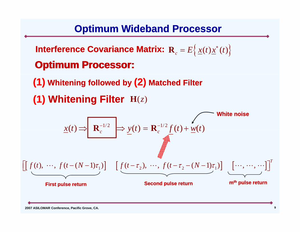
Optimum Wideband ProcessorOptimum Wideband Processor
( ) ( )I t f C i M t iI t f C i M t i ( ) ( )c E x t x tR
Optimum Processor:Optimum Processor:Optimum Processor:Optimum Processor:Interference Covariance Matrix:Interference Covariance Matrix:
(1)(1) Whitening FilterWhitening Filter(1)(1) Whitening followed byWhitening followed by (2)(2) Matched FilterMatched Filter
( )zH(1)(1) Whitening FilterWhitening FilterWhite noiseWhite noise
1/ 2 1/ 2( ) ( ) ( ) ( )x t y t f t w t R R
( )
( ) ( ) ( ) ( )c cx t y t f t w t R R
1 2 2 1( ), , ( ( 1) ) ( ), , ( ( 1) ) , ,T
f t f t N f t f t N
First pulse returnFirst pulse return Second pulse returnSecond pulse return mmthth pulse returnpulse return
2007 ASILOMAR Conference, Pacific Grove, CA. 9
First pulse returnFirst pulse return pp
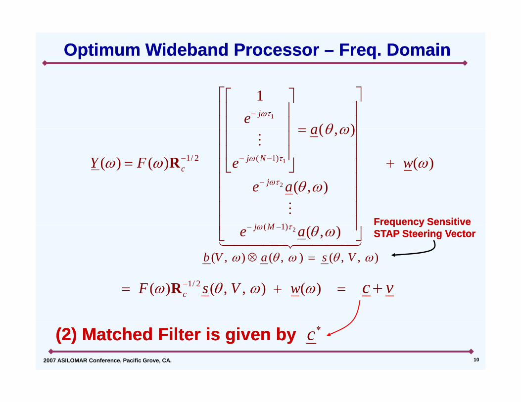
Optimum Wideband Processor Optimum Wideband Processor –– Freq. DomainFreq. Domain
1
1
( )je
a
11/ 2 ( 1)
( , )
( ) ( ) ( )j Nc
a
Y F we
R
2
( 1)
( , )j
j M
e a
Frequency Sensitive Frequency Sensitive
2( 1)
( , ) ( , ) ( , , )
( , )j M
b V a s V
e a
q yq ySTAP Steering VectorSTAP Steering Vector
1/ 2( ) ( , , ) ( )cF s V w c v R
2007 ASILOMAR Conference, Pacific Grove, CA. 10
(2) Matched Filter is given by (2) Matched Filter is given by c
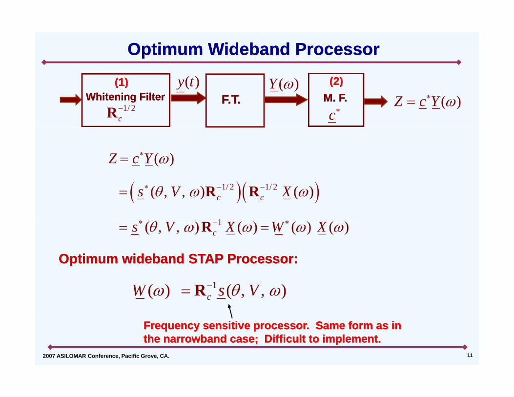
Optimum Wideband ProcessorOptimum Wideband Processor
( )t ( )Y(1)(1) (2)(2)
1/ 2cR
Whitening FilterWhitening Filter F.T.F.T.( )y t ( )Y
cM. F.M. F. ( )Z c Y
(1)(1) (2)(2)
( )Z c Y
1/ 2 1/ 2
1
( , , ) ( )
( ) ( ) ( ) ( )
c cs V X
V X W X
R R
R 1( , , ) ( ) ( ) ( )cs V X W X R
Optimum wideband STAP Processor:Optimum wideband STAP Processor:
1( ) ( , , )cW s V R
2007 ASILOMAR Conference, Pacific Grove, CA. 11
Frequency sensitive processor. Same form as in Frequency sensitive processor. Same form as in the narrowband case; Difficult to implement.the narrowband case; Difficult to implement.

Wideband STAP ProcessorWideband STAP Processor
•• Phase delays become frequency sensitive Phase delays become frequency sensitive filtersfilters
•• STAP Processor must be compensated at STAP Processor must be compensated at allallfrequencies frequencies –– difficult to implementdifficult to implement
In practice, use subband schemes In practice, use subband schemes Subband schemes are suboptimal sinceSubband schemes are suboptimal sinceSubband schemes are suboptimal since Subband schemes are suboptimal since narrowband processing is done on each narrowband processing is done on each subbandsubband
Objective: Avoid subband processingObjective: Avoid subband processing
2007 ASILOMAR Conference, Pacific Grove, CA. 12

Multiple Subband STAPMultiple Subband STAPInput
subbandInput Spectrum
Multiple Beamformers Multiple Beamformers or other STAP methodsor other STAP methods
21 K
or other STAP methodsor other STAP methods
Beamformer 1
Subband Channel 1
1
Beamformer 2
Subband Channel 2
( )x k 2
( , )P V
2
Beamformer
Channel 2
Subband
( )
K
2007 ASILOMAR Conference, Pacific Grove, CA. 13
KChannel KK
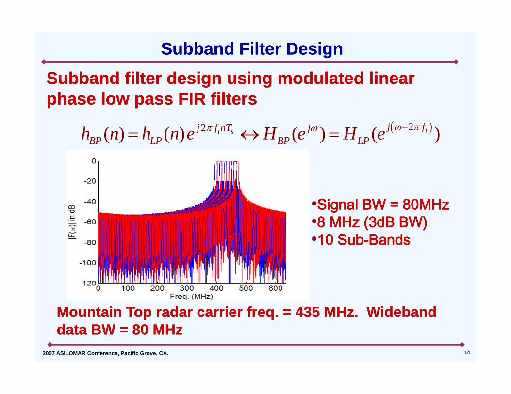
Subband filter design using modulated linearSubband filter design using modulated linearSubband Filter DesignSubband Filter Design
Subband filter design using modulated linear Subband filter design using modulated linear phase low pass FIR filtersphase low pass FIR filters
22 j fj f nT j 22( ) ( ) ( ) ( )ii s j fj f nT jBP LP BP LPh n h n e H e H e
••Signal BW = 80MHzSignal BW = 80MHz••8 MHz (3dB BW)8 MHz (3dB BW)••8 MHz (3dB BW)8 MHz (3dB BW)••10 Sub10 Sub--BandsBands
Mountain Top radar carrier freq. = 435 MHz. WidebandMountain Top radar carrier freq. = 435 MHz. Wideband
2007 ASILOMAR Conference, Pacific Grove, CA. 14
Mountain Top radar carrier freq. 435 MHz. Wideband Mountain Top radar carrier freq. 435 MHz. Wideband data BW = 80 MHzdata BW = 80 MHz

Typical Subband STAP Outputs (SMIDL)Typical Subband STAP Outputs (SMIDL)SMIDL with subarray smoothing using 20 SamplesSMIDL with subarray smoothing using 20 SamplesSMIDL with subarray smoothing using 20 SamplesSMIDL with subarray smoothing using 20 Samples
(a) Subband 1, Freq. = 395 MHz (b) Subband 4, Freq. = 419 MHz
(c) Subband 7, Freq. = 443 MHz (d) Subband 10, Freq. = 467 MHz
2007 ASILOMAR Conference, Pacific Grove, CA. 15
CNR = 40dB, SNR = 0dB, CNR = 40dB, SNR = 0dB, Target at 0Target at 0°° moving at 40m/smoving at 40m/s( ) q
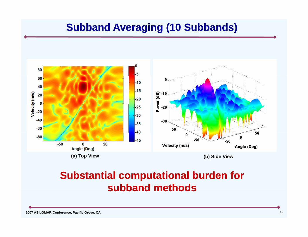
Subband Averaging (10 Subbands)Subband Averaging (10 Subbands)
(a) Top View (b) Side View
Substantial computational burden for Substantial computational burden for subband methodssubband methods
2007 ASILOMAR Conference, Pacific Grove, CA. 16
subband methodssubband methods

New Approach New Approach Subband Combining WithoutSubband Combining WithoutSubband Combining Without Subband Combining Without
Subband PartitioningSubband Partitioning
Objectives:Objectives:jj
•• Use the entire wideband informationUse the entire wideband information
•• Avoid/minimize subbandingAvoid/minimize subbanding
•• Take advantage of narrowband STAPTake advantage of narrowband STAP
2007 ASILOMAR Conference, Pacific Grove, CA. 17
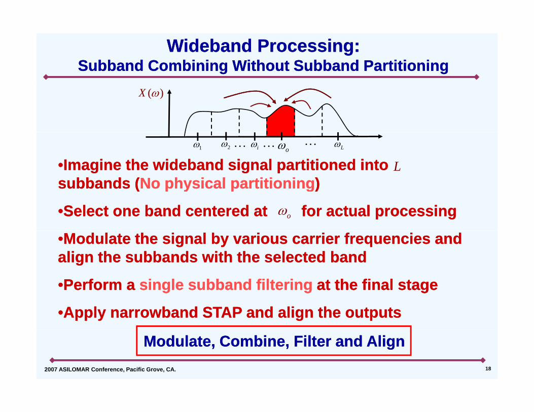
Wideband Processing: Wideband Processing: Subband Combining Without Subband PartitioningSubband Combining Without Subband Partitioning
( )X
••Imagine the wideband signal partitioned into Imagine the wideband signal partitioned into subbands (subbands (No physical partitioningNo physical partitioning))
1 2 i o L
Lsubbands (subbands (No physical partitioningNo physical partitioning) )
••Select one band centered at for actual processingSelect one band centered at for actual processingo
••Modulate the signal by various carrier frequencies and Modulate the signal by various carrier frequencies and align the subbands with the selected band align the subbands with the selected band
P fP f i l bb d filt ii l bb d filt i t th fi l tt th fi l t••Perform a Perform a single subband filteringsingle subband filtering at the final stage at the final stage
••Apply narrowband STAP and align the outputsApply narrowband STAP and align the outputs
2007 ASILOMAR Conference, Pacific Grove, CA. 18
Modulate, Combine, Filter and AlignModulate, Combine, Filter and Align

Subband Combining Without Subband PartitioningSubband Combining Without Subband PartitioningExampleExample
( )X••Original signal with total Original signal with total bandwidth of bandwidth of
( )X
1 o 2
oB
oB••Entire bandwidth is Entire bandwidth is partitioned into subbandspartitioned into subbands
+1( )X
1 o 2
••Data is modulated by Data is modulated by different carrier freq. different carrier freq. and then combinedand then combined
+
+2 ( )X
and then combinedand then combined
••A single band pass filter A single band pass filter is applied to the summed is applied to the summed
+
1 o 2( )BFH
2
2( )
0( ) ( ) ( )o kj n
BPk
y n x n e h n
Bandpass Bandpass filterfilter
ppppdatadata
1 o 2 0k
( )Y 1 2( ) ( ) ( ) ( ) ( )BPY X X X H
Narrowband STAP onNarrowband STAP on ( )y n
2007 ASILOMAR Conference, Pacific Grove, CA. 19
1 o 2
Narrowband STAP onNarrowband STAP on ( )y

Modulate, Combine and Filter Modulate, Combine and Filter –– 10 Modulations 10 Modulations DopplerDopplerDoppler Doppler spreadspread
(a) Top View (b) Side View
Data is modulated by 10 carrier frequencies to 435 MHz. Data is modulated by 10 carrier frequencies to 435 MHz. SMIDL i d t t 435 MH ith 10 lSMIDL i d t t 435 MH ith 10 l
(a) Top View (b) Side View
2007 ASILOMAR Conference, Pacific Grove, CA. 20
SMIDL using data at 435 MHz with 10 range samples.SMIDL using data at 435 MHz with 10 range samples.

Modulate, Combine and Filter Modulate, Combine and Filter –– 20 Modulations 20 Modulations DopplerDopplerDoppler Doppler spreadspread
(a) Top View (b) Side View
Data is modulated by 20 carrier frequencies to 435 MHz. Data is modulated by 20 carrier frequencies to 435 MHz. SMIDL i d t t 435 MH ith 10 lSMIDL i d t t 435 MH ith 10 l
(a) Top View (b) Side View
2007 ASILOMAR Conference, Pacific Grove, CA. 21
SMIDL using data at 435 MHz with 10 range samples.SMIDL using data at 435 MHz with 10 range samples.

Modulate, Combine, Filter and AlignModulate, Combine, Filter and Align
A single target at in the filtered dataA single target at in the filtered data••A single target at in the filtered data A single target at in the filtered data generates multiple direction vectors generates multiple direction vectors corresponding to frequenciescorresponding to frequencies
1
corresponding to frequencies corresponding to frequencies
••Or equivalently, processing at generates Or equivalently, processing at generates 1 2, , , L
omultiple targets at where multiple targets at where 1 2, , , L
1sin sin , 2, 3, ,o k k k L
••“Angle“Angle--Doppler spread” in STAP output Doppler spread” in STAP output spectrum processed at a single frequencyspectrum processed at a single frequency
1 , , , ,o k k
spectrum processed at a single frequency spectrum processed at a single frequency
••Align the angleAlign the angle--Doppler spectrum to Doppler spectrum to o
2007 ASILOMAR Conference, Pacific Grove, CA. 22
compensate for the Doppler spreadcompensate for the Doppler spread

••Target returnTarget return
Waveform Design for Coherent CombiningWaveform Design for Coherent CombiningSpatioSpatio--temporal temporal
( ) ( ) ( , , )tt t dS S a
••Target returnTarget return
T itT it
steering vectorsteering vector
( )S
Transmit Transmit WaveformWaveformDesirable Tx WaveformDesirable Tx Waveform
( )S Undesirable Tx WaveformUndesirable Tx Waveform
1 o 2 1o
2
••Transmit waveform magnitude/phase variations should Transmit waveform magnitude/phase variations should be minimized (Waveform Design)be minimized (Waveform Design)( g )( g )
••Present method avoids subband processing (one Present method avoids subband processing (one subband only) and uses the entire wideband informationsubband only) and uses the entire wideband information
2007 ASILOMAR Conference, Pacific Grove, CA. 23
••Takes advantage of narrowband STAPTakes advantage of narrowband STAP

ConclusionsConclusions
••Method presented here is ideal for initial Method presented here is ideal for initial search over a large regionsearch over a large regionsearch over a large regionsearch over a large region
••Present method avoids subband Present method avoids subband processing (one subband only) and uses processing (one subband only) and uses the entire wideband informationthe entire wideband information
••Doppler spreading needs to be Doppler spreading needs to be compensatedcompensatedcompensated compensated
••Use waveform diversity for coherent Use waveform diversity for coherent
2007 ASILOMAR Conference, Pacific Grove, CA. 24
combining.combining.


![A DSP-Based Space Vector Modulation Direct Torque …journal.esrgroups.org/jes/papers/5_3_4.pdf · complex. In [10, 11], discrete space vector modulation DTC approach is used to reduce](https://img.pdfslide.us/doc/110x75/5a953d657f8b9adb5c8c5e69/a-dsp-based-space-vector-modulation-direct-torque-in-10-11-discrete-space.jpg)