Embed Size (px)
Citation preview

Part One
Phase I: Project Requirement
Section 1
Project Overview
1.1 Purpose
Elections are one of the most critical functions of democracy. Not only do they provide for the
orderly transfer of power, but they also cement citizens’ trust and confidence in government when
they operate as expected. The events that transpired in Florida during the 2000 presidential
election focused national attention on how elections are administered.
The subject of voting systems has taken center stage, and is under intense scrutiny by
policymakers, interest groups, and the American people in general. Over the last year, there has
been strong interest in voting over the Internet as a way to make voting more convenient and
precise. In addition to adding convenience and precision, it is believed that Internet voting may
reverse the historical and downward trend of voter turnout in the United States.
As an MSE project, this project will define the scope of the Internet voting system for
Kansas State elections from the technical perspectives and address the technical
challenges. Within this scope, a model of the Internet voting system will be set up, and
the corresponding technical and design requirements will be analyzed and specified in a
formal language; approaches and methodologies to the addressed challenges will be
proposed and implemented. Naturally, all the requirements have to be met when the
model is implemented. The topics addressed in this project, while all related to Internet
voting, are also relevant to discussions about other electronic voting systems.
1.2 Constraints
Internet voting is seen as a logical extension of Internet applications in commerce and
government. In the wake of the 2000 election, Internet systems are among those being considered
to replace older, less reliable systems. Election systems, however, must meet standards with
regard to security, secrecy, equity, and many other criteria, making Internet voting much more
1

challenging than most electronic commerce or electronic government applications. The contested
2000 Presidential election highlighted awareness of the critical importance of ensuring
confidence in the integrity and fairness of election systems.
Technological threats to the security and integrity of Internet ballots are significant. The
possibility of "Virus" and "Trojan Horse" software attacks on home and office computers
used for voting is very real and, although they are preventable, could result in a number
of problems ranging from a denial of service to the submission of electronically altered
ballots.
One of the most difficult tasks for an Internet voting system is the authentication of
voters. To ensure that every voter has the opportunity to cast a ballot and no voter is able
to vote more than one time, this task force believes election officials should initially test
Internet Voting technology through the use of Internet Voting machines that are under the
direct control of election personnel in traditional polling places.
Eventually, election officials can transition toward allowing voters to cast ballots at
publicly accessible county-controlled kiosks or computers and, in the future, provide the
option of remote computer voting from any computer with Internet access.
The democratic process warrants an extremely high level of security, but the security
measures cannot be so cumbersome to voters that the new process would prevent
participation. An appropriate balance between security, accessibility and ease of use must
be achieved before Internet voting systems should be deployed.
1.3 Directions
Despite these challenges, it is technologically possible to utilize the Internet to develop a
method of voting. At this time, it would not be legally and practically to develop a
comprehensive remote Internet voting system that would completely replace the current
paper process used for voter registration, voting, and the collection of initiative,
referendum and recall petition signatures.
To achieve the goal of providing voters with the opportunity to cast their ballots at any
time from any place via the Internet, this task force believes that the elections process
would be best served by a strategy of evolutionary rather than revolutionary change.
2

As with most computer systems, increased security and higher levels of privacy can be
provided by increasing the complexity and the burden on the user of the system. The
success or failure of Internet voting in the near-term may well depend on the ability of
computer programmers and election officials to design a system where the burden of the
additional duties placed on voters does not outweigh the benefits derived from the
increased flexibility provided by the Internet voting system.
1.4 Reference:
1. http://www.acm.org/crossroads/xrds2-4/voting.html
2. http://www.calvoter.org/
3. http://www.cpsr.org/conferences/cfp93/shamos.html
4. http://www.netvoting.org/
3

Section 2
Software Requirement Specification
2.1 Introduction
This is a software requirement specification (SRS) for Internet Voting Management
System which includes components IVS Manager, Database Connection Manager, Query
Processing, Server, Mail Sender and Client component in Internet Voting project. It is
used to specify the requirement for the initial implementation of the system and up to
date in the future. The audience of this document is voting software designer,
implementer and tester, voting system manager, and voter.
2.1.1 Purpose
The purpose of this software requirement specification is to define the requirements that
will enable the development of the IVS Manager, Database Connection Manager, Query
processing and Server - and Client components. This specification can be updated in the
future to incorporate a new version of any of the components.
2.1.2 Scope
There will be two functional components developed using this SRS. The first will be the
IVS Manager. The essence of this component is to keep safe the information of the valid
voters, candidates and ballots. The IVS manager functional component includes the
server, query processing, database connection manager and mail sender. The IVS
manager accepts requests from clients by server, distributes query and converts the query
to executable statement by query processing; updates the database and gets the result
from database by connection manager; retrieves the data to server, then send back data to
client. The mail sender will send the voter password requests to voters’ email account.
The goal of IVS manager is to provide and store accurate information about the voters,
candidates, and the ballots. However, none of the other voters except the voter himself is
allowed to access the ballot; none of the voters except the authorized agency is allowed to
access the statistical result of the election which may be subject to further validation or
4

inspection. By limiting the access to ballot exclusively to the one who casts it, the
personal privacy concerning political opinion is protected.
The second component will be the Client. This component will provide the voter with
information that is to be authenticated and the ballot for the voter to cast. These interfaces
are open for the voter to input and will return authentication information for the voter to
confirm the input and the cast. A voter does not have the right to modify his personal
information or the candidate information under any circumstances. However, addition of
new candidates may be allowed. Further plans are for providing cross-reference or search
tools, etc.
2.1.3 Definitions, acronyms, and abbreviations
SLOC – Source Line of Code.
Connection Pool Manager – a program component providing the connection
to query processing with database
Query processing – a program component providing the communication
server and database.
Server – a program component providing services to remote voters.
Mail Sender – a program component providing services to send email to
voters
Client – a program component providing login and online ballot.
IEEE – Institute of Electrical and Electronics Engineers
SRS – Software Requirement Specification
2.1.4 References
IEEE Std-830, IEEE New York, 1993.
Course slides from Dr. David A. Gustafson,
www.cis.ksu.edu/~gustafson/cis748.
Emphasizing Software Quality in Undergraduate Programming Laboratories,
Frontiers in Education conference in 1998.
Pressman, Software Engineering: A Practitioner’s Approach. Fourth Edition,
McGraw Hill 1997.
5

Software Requirement Engineering and Management Process
http://utexas.edu/coe/sqi/seminar/SWRep.html
2.2 Overall Description
This section involves the description of the software being developed and the
corresponding requirements. The product will be compared with other similar products.
A description of any constraint that the product optionally has will be provided. This
project will implement part of following features due to time constraint of MSE project.
Specifically,
• Approaches to meeting the security, secrecy, scalability, and convenience requirements
of elections. Particular emphasis should be placed on the development of secure voting
platforms, and secure network architectures;
• Development of methods to reduce the risk of insider fraud;
• Development of reliable poll site and kiosk Internet voting systems that are not
vulnerable to any single point of failure and cannot lose votes;
• Development of new procedures for continuous testing and certification of election
systems, as well as test methods for election systems;
• The effects of potential open architecture and open source code requirements on
innovation, profitability, and public confidence;
• Human factors design for electronic voting, including the development of appropriate
guidelines for the design of human interfaces and electronic ballots, as well as approaches
to addressing the needs of the disabled;
• Protocols for preventing vote selling and reducing coercion;
• The economics of voting systems, including comparative analyses of alternative voting
systems;
• The effects of Internet voting on participation in elections, both in general and with
regard to various demographic groups—especially those with less access to or facility
with computers;
• The effects of Internet voting on elections, the public’s confidence in the electoral
process, and on deliberative and representative democracy;
• The implications of Internet voting for political campaigns;
6
• The appropriate role of the federal government in state-administered elections;
• Legal issues associated with and the applicability of existing statutes to Internet voting,
including jurisdiction, vote fraud, liability for system failures, international law
enforcement, and electioneering;
• Electronic authentication for kiosk and remote voting; and
• Experimentation, modeling, and simulation of election systems.
2.2.1 Product perspective
The IVS Manager, Client components will be dependent on the main interface of the IVS.
They are also interleaved with other components for message passing. The block
diagram for the total system in Figure 1 is shown on next page to represent the
relationship among the components.
Figure 1: IVS System sketch
2.2.2 Product functions
The IVS manager component will adopt some basic functions. These functions are:
Query Processing
DatabaseConnection
Manager
Query Processing
Server
Client
ConClient
ConClient
Server
DBM
MailSender
Query Processing
7

set up administrator login – define the administrator ID and password;
set up database – define candidates data and voters data;
set up voting period – define voter starting time and stop time;
initialize the server – set up the connection manager and cache manager;
run server – startup the server;
count the ballots – get the voting result.
The user diagram:
login
IVSM
enter passwd
setup database
schedule voting
initialize pool
run server
administrator
show result
Figure 2: User Diagram of IVSM
The Server will adopt some basic functions. These functions are:
accept – wait for any visiting.
query – get the data under the entered topic.
cache – store the data which will be available to next query
send– send the required data to the client.
The user diagram:
8

accept
query
cache
IVSM
send
server
Figure 3: User Diagram of Server
The client component will adopt some basic functions. These functions are:
login – confirm ID and cost a ballot.
vote – vote the candidate.
The User Diagram
client voter
login
vote
Figure 4: User Diagram of Client
2.2.3 User characteristics
The components will be produced as a project whose primary user will be citizens and
official voting administration in Kansas State. For such a case, the software will be
9

written in a manner in which it is assumed that the voters have no knowledge about the
software. The official voting administration who manager the voting should have basic
knowledge to launch the server. The user also must have the ability to interact with a
computer, using the keyboard and/or mouse.
2.2.4 Constraints
Java JDK 1.1.7 above, Internet browser, such as Netscape 4.0 or above, or Internet
Explore 4.0 or above must be installed in order to use this product. The component codes
must be compiled together with other components in order to integrate them together.
2.2.5 Assumptions and dependencies
It is assumed that the administrator can maintain the system properly and the database
will be set up properly. The voters ID and Code will be distributed in a private way. This
system will not handle the validity of citizen voting right. It is also assumed that the user
has background in the basic use of the GUI programs and the basic operation of the
computer.
2.2.6 Apportioning of requirements
The proper setup of the dataset and the structure of the database will affect the total
structure of the IVS manager components.
2.3 Specific Requirements
2.3.1 External interface requirements
There are four categories in this section. They are the interfaces of the user, hardware,
software, and communication respectively.
2.3.1.1 User interfaces
A Graphic User Interface (GUI) with all menus, toolbars, dialog box, and buttons should
be user friendly so that the user can run the program more efficiently.
10

2.3.1.2 Hardware interfaces
This project should be platform independent since Java is used as the programming
language.
2.3.1.3 Software interfaces
All the software interfaces among the components and classes are adapted from Java JDK
library, Java mail API, Oracle Database Driver.
2.3.1.4 Communication interfaces
The communication interfaces will be built using Java JDK library either appearing as
GUI or hiding into the system.
2.3.2 Classes / Objects
For the IVS Manager:
ADMINISTRATORS– will store the administrator’s name and password.
CONNECTION POOL – store the connection to the database for reusing of next
query.
CONNECTION MANAGER – will manager the connection which server
requests.
Mail Sender – will send emails to voters for their requests and result.
QUERY WRAPER – will handle information query between database and server.
IVS Manager – will have a GUI and manager all other object.
SERVER – will accept the voter logging on and kick out the idle logging and
dead connection.
Ballot – record the candidates of this election
Candidate – candidate data placeholder.
Message – send between server and client
11

Candidate
IVSM
ConnectionPool
ConnServer
ConnManager
QueryWrapper
Ballot
Ticker
Trigger
Server
MailSender
Administrator
Figure 5: Class Diagram of IVS Manager Component
For the Client:
CONCLIENT – connect to the server and communicate with it.
BALLOT – display the ballot.
VCLIENT – will manager data communication.
TIMEOUT THREAD – will restore the system to init status.
12

TimeroutThread
VClientBallot
ConnClient
Candidate
Figure 6 Class Diagram of Client Component
2.3.3 Performance requirements
This project is not processor intensive. The tool would not have any large memory
requirements and would not cause overloading of the system resources. No special
hardware and software consideration needs to be taken into account.
2.3.4 Design constraints
The components in this project come from the total IVS. All other components should be
integrated properly in order to make the total system working well.
2.3.5 Software system attributes
The system will provide all the integrated interfaces among all the components for
message passing. Also the system will verify the voter id and password when the voter
first logs in the system.
2.3.6 Other requirements
13

More important, the instructor will play an important role in the total system. She has
done many researches in software engineering and database management and is familiar
with the standard techniques of the software engineering. She has also supervised many
master projects in the area of software engineering, database management, distributed
system.
2.4 References
IEEE Standard 830, IEEE New York, 1993.
Pressman, Software Engineering: A Practitioner’s Approach. Fourth
Edition, McGraw Hill 1997.
Software Requirements Engineering and Management Process
http://utexas.edu/coe/sqi/seminar/SWRep.html
John L. Connell, Object-Oriented Rapid Prototyping. Prentice Hall 1995
James Noble, Prototype-Based Programming. Springer 1999
Section 3
14
Cost Estimate
3.1 Introduction
In this project, Function Point Analysis and COCOMO model are used for estimating the
size and cost of developing the tool. Function point analysis is used to estimate the
source lines of code. The IVS for java code is calculated after the function points are
calculated. COCOMO model is used to estimate the cost estimation of the project.
Number of man-months is calculated from the IVS using COCOMOII calculator. And
also a Gantt chart is plotted from the available man-months.
3.2 Function Points Analysis
The function point model includes three major steps for the cost estimation. First,
calculate the unadjusted function points (UFP) by counting the identical types, input,
output, file, inquiry, and interface. Second, calculate the adjusted function point (AFP)
based on the unadjusted function point and product complexity adjustment (PC). Third,
calculate the source lines of code (SLOC) based on the adjusted function point and
language factor (LF).
3.2.1 Calculate UFP
Calculate for the unadjusted function points (UFP) through classifying and counting
different types. There are five file types. They are external input type, external output
type, logical internal file type, external interface, and external inquiry type. External
input types refer to each user input that provides distinct application-oriented data to the
software.
External output types refer to the user output that provides application-oriented
information to the user. Logical internal file type refers to data stored for an application,
as logically viewed by the user. External interface refers to
all machine readable interfaces (e.g. data files on tape or disk) that are used to transmit
information to another system. External inquiry refers to a n
on-line input that results in the generation of some immediate software response in the
form of an on-line output.
15

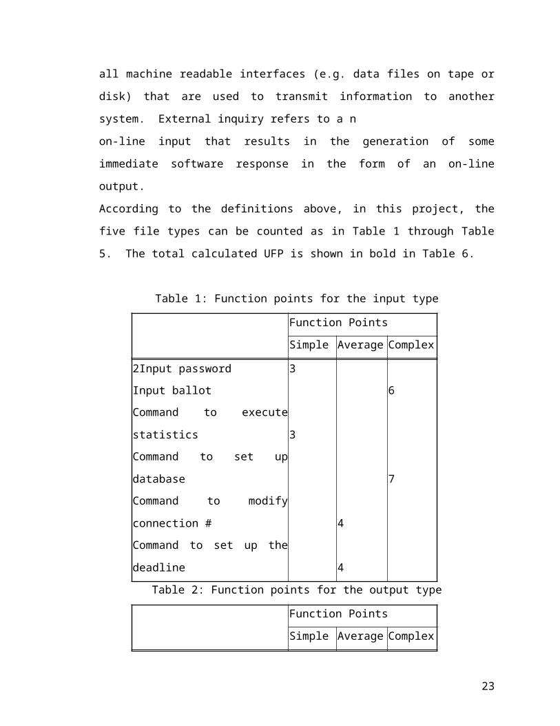
According to the definitions above, in this project, the five file types can be counted as in
Table 1 through Table 5. The total calculated UFP is shown in bold in Table 6.
Table 1: Function points for the input type
Function Points
Simple Average Complex
2Input password 3
Input ballot 6
Command to execute statistics 3
Command to set up database 7
Command to modify connection # 4
Command to set up the deadline 4
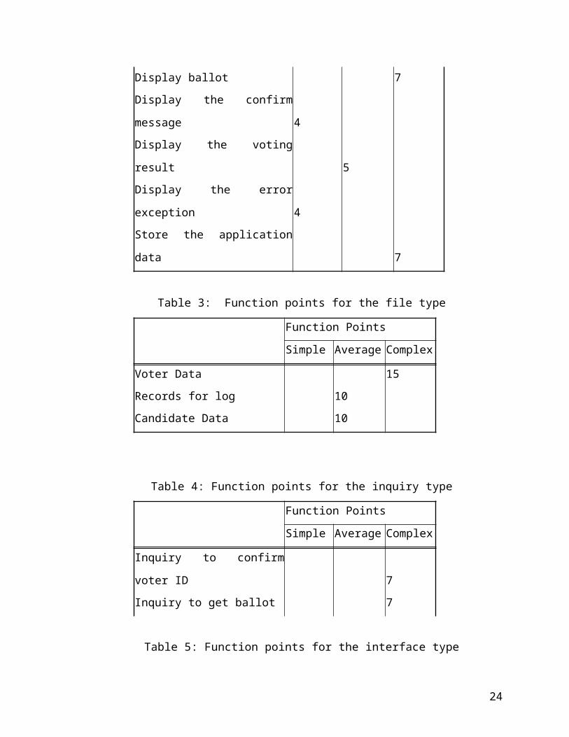
Table 2: Function points for the output type
Function Points
Simple Average Complex
Display ballot 7
Display the confirm message 4
Display the voting result 5
Display the error exception 4
Store the application data 7
Table 3: Function points for the file type
Function Points
Simple Average Complex
Voter Data 15
Records for log 10
Candidate Data 10
Table 4: Function points for the inquiry type
16

Function Points
Simple Average Complex
Inquiry to confirm voter ID 7
Inquiry to get ballot 7
Table 5: Function points for the interface type
Function Points
Simple Average Complex
Server to local machine 10
Server to database server 10
Remote 10
Table 6: Total function points for all the types
Function Points Total
Simple Average Complex Function Points
Value Amount Value Amount Value Amount
Inputs 3 3 4 1 6 1 19
Outputs 4 2 5 1 7 2 27
Files 10 2 15 1 35
Inquiries 7 2 14
Interfaces 10 2 20
Total 115
3.2.2 Calculation for the adjust for the processing complexity (PC)
To decide the processing complexity, several factors have to be taken into account, e.g.,
backup and recovery, code design for reuse, etc. All the factors and their estimated
values in this project are shown in Table 7. The Processing Complexity is shown in
BOLD letter and the calculation formula is shown in the next section.
17

Table 7: Summary of function point influence factors
Complexity Weighting Factor Value
Backup and recovery 1
Data communications 5
Distributed processing 5
Performance critical 5
Existing operating environment 4
On-line data entry 3
Input transaction over multiple screens 0
Master files updated on-line 3
Information domain values complex 5
Internal processing complex 4
Code designed for reuse 5
Conversion/installation in design 3
Multiple installations 3
Application designed for change 5
Sum of complexity weighting factors 48
Complexity adjustment factor 1.13
3.2.3 Calculation for the source lines of code (SLOC) and the formulas used
Total Unadjusted Function Points (UFP) = 115
Product Complexity Adjustment (PC) = 0.65 + (0.01 *48) = 1.13
Total Adjusted Function Points (FP) = UFP * PC = 122
Language Factor (LF) for Java assumed as = 38
Source Lines of Code (SLOC) = FP * LF = 5100
3.3 Cost Estimation By COCOMO Model
To simplify the calculation, we can refer to the Table 8 for selecting the correct formula
for this project. This project is in the type of application program, therefore we can select
the associated formula to calculate the PM and TDEV.
18
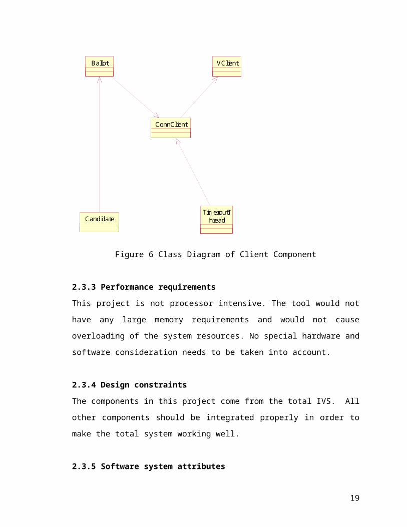
Table 8: Summary of formulas for different programs
Programmer Development Time
TDEV Productivity (Month)
Application Programs
PM = 2.4*(KDSI) 1.05 TDEV = 2.5* (PM) 0.38
Utility Programs
PM = 3.0*(KDSI) 1.12 TDEV = 2.5*(PM) 0.35
System Programs
PM = 3.6*(KDSI) 1.20 TDEV = 2.5*(PM) 0.32
KDSI = 5.1 KLOC
PM = 2.4*(KDSI) 1.05 = 13 person-month
TDEV = 2.5 * (PM) 0.38 = 6.7 month
3.4 References
Software Engineering: A practitioner’s approach by Roger S. Pressman
Lecture Notes from Dr. David A. Gustafson, http : //www.cis.ksu.edu/~dag
19
Section 4. Project Plan
This project plan includes the total schedule for the project at all the three phases.
4.1 Phase One: Requirements
August 23, 2001 to November 16, 2001
1 Literature Review: August 23, 2001 to August 27, 2001
Learn the basic concepts and understand the software requirement, specification
design and testing techniques; read literature on electronic voting systems.
2 Overview: August 28, 2001 to September 12, 2001
Write project overview, including the purpose, background, constraints, and
requirements.
3 Project Plan: September 8, 2001 to October 14, 2001
Set up milestones of the project; draw the corresponding Gantt chart.
4 Software Requirement Specification: September 14, 2001 to October 8, 2001
Document overall requirements of the project; draw system model, scenarios.
5 Cost estimation: September 3, 2001 to September 7, 2001
Document the estimation of the size, cost and effort required for the project,.
6 MSE presentation (phase I): October 15, 2001
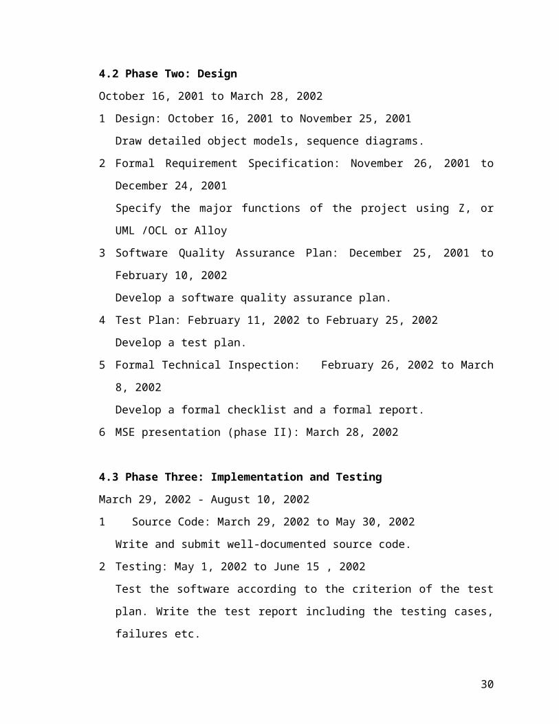
4.2 Phase Two: Design
October 16, 2001 to March 28, 2002
1 Design: October 16, 2001 to November 25, 2001
Draw detailed object models, sequence diagrams.
2 Formal Requirement Specification: November 26, 2001 to December 24, 2001
Specify the major functions of the project using Z, or UML /OCL or Alloy
3 Software Quality Assurance Plan: December 25, 2001 to February 10, 2002
Develop a software quality assurance plan.
4 Test Plan: February 11, 2002 to February 25, 2002
Develop a test plan.
5 Formal Technical Inspection: February 26, 2002 to March 8, 2002
20

Develop a formal checklist and a formal report.
6 MSE presentation (phase II): March 28, 2002
4.3 Phase Three: Implementation and Testing
March 29, 2002 - August 10, 2002
1 Source Code: March 29, 2002 to May 30, 2002
Write and submit well-documented source code.
2 Testing: May 1, 2002 to June 15 , 2002
Test the software according to the criterion of the test plan. Write the test report
including the testing cases, failures etc.
3 Project Evaluation: June 16, 2002 to July 1, 2002
Review the methodologies and quality of the project.
4 User Manual: July 2, 2002 to July 26, 2002
Compile a user manual that includes common usage of the software.
5 Documentation: July 27, 2001 to August 2, 2002
Edit and finish up the final version of the software with cited references.
6 Final MSE presentation (Phase III): August 12, 2002
21
4.4 Gantt Chart
ID Task Name1 Literature Rev iew
2 Overv iew
3 Cost Estimatation
4 Project Plan
5 SRS
6 MSE Presenatation 1
7
8 Design
9 Formal Requirement Specif ication
10 Sof tware Quality Assurance Plan
11 Test Plan
12 Formal Technique Rev iew
13 MSE Presentation 2
14
15 Code Development
16 Testing
17 Project Evaluation
18 User Manual
19 Documentation
20 Final Presentation
10/15
3/28
8/12
F S S M T W T F S S M T W T F S S M TJul 29, '01 Sep 16, '01 Nov 4, '01 Dec 23, '01 Feb 10, '02 Mar 31, '02 May 19, '02 Jul 7, '02 Aug 25, '02
Figure 7: Gantt Chart of Project Plan
22
Section 5
Time Log for Phase One
Date Start Stop Time Activity Comment
8/2/01 3:00 3:30 0.5 hr Meet with Dr.
Bleyberg
Initial meeting
8/4/01 9:00 11:00 2 hrs Read materials Preparation
8/9/01 3:00 3:30 0.5 hrs Meet with Dr.
Bleyberg
Discuss the
project
8/11/01 2:00 3:00 1 hrs Read materials Choose topic
8/16/01 3:00 4:30 1.5 hrs Meet with Dr.
Bleyberg
Choose topic
8/18/01 2:00 4:00 2 hrs Read material Choose project
8/23/01 3:00 3:30 0.5 hrs Meet with Dr.
Bleyberg
Discuss project
8/25/01 2:00 6:00 4 hrs Read material Prepare for the
project
8/26/01 2:00 6:00 4 hrs Read material Prepare for the
project
8/30/01 3:00 3:30 0.5 hr Meet with Dr.
Bleyburg
Discuss the
project
8/31/01 2:00 5:00 3 hrs Design
9/1/01 1:00 6:00 5 hrs Read MSE
project
9/2/01 2:00 4:00 2 hrs Read MSE
project
9/3/01 8:00 11:00 3 hrs Software
Requirement
Specification
(SRS)
23
9/4/01 1:00 4:00 3 hrs SRS
9/5/01 2:00 6:00 4 hrs Modify SRS
9/6/01 2:00 5:00 3 hrs SRS Add new content
9/8/01 3:00 6:00 3 hrs System diagram
9/9/01 9:00 11:00 2 hrs More diagram OK
9/10/01 2:00 6:00 4 hrs SRS Add new content
9/11/01 2:00 4:30 2.5 hrs SRS
9/12/01 8:00 12:00 4 hrs SRS Overview
9/13/01 3:00 3:30 0.5 hr Meet with Dr.
Bleyberg
Discuss SRS
9/15/01 2:00 6:00 4 hrs SRS OK
9/18/01 2:00 3:00 1 hr Review
9/20/01 2:00 6:00 4 hrs Project plan
9/22/01 9:30 12:00 2.5 hrs Project plan OK
9/25/01 2:00 6:00 4 hrs Cost estimate
9/28/01 2:00 5:30 3.5 hrs Cost estimate
9/30/01 8:00 9:00 1 hr Cost estimate OK
10/5/01 2:00 5:00 3 hrs Review the
document
10/8/01 2:00 5:00 3 hrs Prepare for
presentation I
Make slides
10/9/01 11:00 12:00 1 hr Prepare for
presentation
10/10/01 2:00 6:00 4 hrs Prepare for
presentation
10/11/01 3:00 3:30 0.5 hr Meet with Dr.
Bleyberg
Discuss
presentation
10/15/01 2:30 3:30 1.0 hrs Presentation OK
24

Part Two
Phase II: Project Design
Section 6
Software Quality Assurance Plan
An important part of achieving quality is to plan for quality, that is, to plan those
activities that will help to achieve quality. The software quality assurance (SQA) plan is
to provide a guideline for activities that will ensure the quality of software. I use the
IEEE standard Std 730-1989 for developing the Software Quality Assurance Plan
(SQAP) of my project.
6.1 Purpose
This SQA plan covers the software requirement, design, and implementation phases
of the development of Internet Voting System Manager (IVSM). This plan does not
cover the Cryptix and the Cryptix software that will be used by my project.
This SQAP provides a foundation for managing the IVSM software quality assurance
activities, and is based on project activities and work products as documented in the
project plan. This SQAP plan:
Identifies the SQA responsibilities of the project developer and the SQA
consultant
Defines how to review and audit the development of IVSM system.
Lists the activities, processes, and work products that the SQA consultant will
review and audit
Identifies the SQA work products
6.2 References
Software Engineering, Roger S. Pressman
Lecture Notes, CIS541 Software Engineering II, Dr. David Gustafson, Spring
2001.
25

Lecture Notes, CIS740 Advanced Software Engineering, Dr. David
Gustafson, Fall 1999.
Lecture Notes, CIS748 Software Management, Dr. David Gustafson, Summer
1998.
IEEE Standard for Software Test Documentation, IEEE Std 829-1983
IEEE Standard for Software Quality Assurance Plans, ANSI/IEEE Std 730-
1989
IEEE Guide for Software Quality Assurance Planning, DRAFT, P730.2/D4
6.3 Management
Organization:
The committee consists of Dr. Maria Zamfir-Bleyberg, Dr. William Hsu and
Dr. Gustafson
Major Professor: Dr. Maria Zamfir-Bleyberg
Developer: MSE student Yonghua Li.
Tasks:
Develop the requirement specification, cost estimation for distributed multiple
sequence alignment system.
Develop the design plan and test plan for distributed multiple sequence
alignment system.
Implement and test the distributed multiple sequence alignment system.
Deliver the final version along with the documentation.
On completion of the analysis, design and testing phases, the developer gives
a formal presentation to the committee. The committee reviews the work
performed by the developer and provides feedback.
Responsibilities
The developer will perform all software development tasks for internet voting
system manager under the supervision of the major professor.
26

The committee will review the work performed by the developer and provide
feedback and advice.
6.4 Documentation
The following documents will be provided at the end of each phase.
Phase 1: Software Requirement
Project Overview
System Diagram
Project Gantt Chart Timeline
Cost Analysis
System Requirements Specification (SRS)
Time Log
Phase 2: Software Design
Software Quality Assurance Plan (SQAP)
Object Model
Formal Specifications
Test Plan
Formal Technical Review (checklist)
Time Log
Phase 3: Software Implementation
Source Code
User Manual
Testing and Reliable Evaluation
Project Evaluation
Final Report
Time Log
27

Appendix:
Source Code
6.5 Standard, Practices, Conventions, and Metrics
Standards
Document Standards – MSE portfolio
Coding Standards - Java 1.2
Coding Documents - Java Documentation
Test Standards - IEEE Standard for Software Test
Documentation
Metrics
LOC - line of code is used to measure the size of the software
6.6 Review and Audits
There will be three formal presentations prepared by the developer and evaluated
by the committee at the end of each phase (Requirement, Design, and Implementation).
In the preliminary design review at the end of design phase, the technique adequacy of
top-level design will be evaluated. All documents pertaining to one specific phase will be
presented at the review. The evaluation is subject to be approved by the committee
members. All deficiencies or inconsistency must be rectified by the developer and
resubmitted to the committee members for approval.
6.7 Test, Tools, Techniques, and Methodologies
A Software Test Plan (STP) will be written to satisfy the software requirements. The
plan will provide management and the testing function with an overview of the test
activities, schedules and resources required to perform testing. The plan will describe
how the testing specifications found in the following sections will be implemented.
28

Unit Test:
All code will be unit tested to ensure that the individual unit (class) performs the
required functions and outputs the proper results and data.
Integration Test:
There are two levels of integration testing. One level is the process of testing a
software capability. A second level of integration testing occurs when sufficient
modules have been integrated to demonstrate a scenario.
Java Virtual Machine will be used for this project during the implementation. For
measuring the size of the project, the function points analysis and COCOMO II were
used. The design of the project is object oriented. Rational-Rose was used for making
object diagram.
I will use the Cryptix framework to encrypt the communication between the
server and client.
6.8 Problem Reporting and Corrective Action
During the whole development process of the project, the developer can report the
problems to his major professor or his committee member. The major professor or
committee member gives their suggestions. In the three presentations, the major
professor or committee member also can ask questions and give their advice. After
presentation, the developer corrects his mistakes.
6.9 Code control
N/A
6.10 Media control
N/A
6.11 Supplier control
29
The source code of the Cryptix and the Cryptix frameworks are from their
developer’s website. Assume that all these source code are reliable.
6.12 Records
All the documents of each phase will be posted on my personal website in the CIS
department. At the end of the phase III, the thesis composed of all the documents of the
project will be committed to the CIS department.
6.13 Training
CIS540 Software Engineering Project
CIS740 Software Engineering
CIS748 Software Management
6.14 Risk Management
The most important risk is that the Cryptix framework is from third party. We do not
know how well it works. I plan to run this system with boundary testing cases first,
then apply it to general running.
Section 7
30
Formal Specification
-----------------------------------------------------------------------------------------------------------
-- Beginning of the formal specification
-- This is the OCL(USE) specification of internet voting manager system.
-- This is the result of validating the UML model and OCL constrains by using USE tool
--------------------------------------------------------------------------------------- --------------------
---compiling specification revised_mse.use...
---done.
---Model IVSM (11 classes, 14 associations, 13 invariants, 9 operations)
------------------------------------------------------------------------------------------------------------
model IVSM
enum TYPE
{SHUTDOWN,DISCONNECT,INIT,PWDREQUEST,WAITCONFIRM,CONFIRM,CO
NFIRMFAIL,BALLOT,WAITBALLOT,VOTEDBALLOT,WARNING,MULTILOG,T
HANK}
-- classes
-- class DB
class DB
attributes
url:String
end
-- class voter
class Voter
attributes
id:Integer
31

name:String
pwd:String
voted:Boolean
operation
vote()
end
-- class candidate
class Candidate
attributes
name:String
comm:String
votes:Integer
voted:Boolean
operation
voted()
end
-- class committee
class Committee
attributes
name:String
position:Integer
end
-- class administrator
class Administrator
attributes
id:String
password:String
32

operations
verifyPassword(password:String):Boolean
end
-- class Ballot
class Ballot
end
-- class IVSM
class IVSM
attributes
startTime:Integer
overTime:Integer
end
-- class server
class Server
attributes
MaxInactivity:Integer
currentTime:Integer
operations
run()
tick()
end
-- class ConClient: the client who is logging on
-- In this class, the boolean variable inCritical to model the conclient to update the DB
class ConClient
attributes
key:String
33

status:TYPE
inactivity:Integer
inCritical:Boolean
operations
enterCritical()
exitCritical()
run()
end
-- class Voting Client
class VClient
attributes
id:Integer
status:TYPE
operations
run()
end
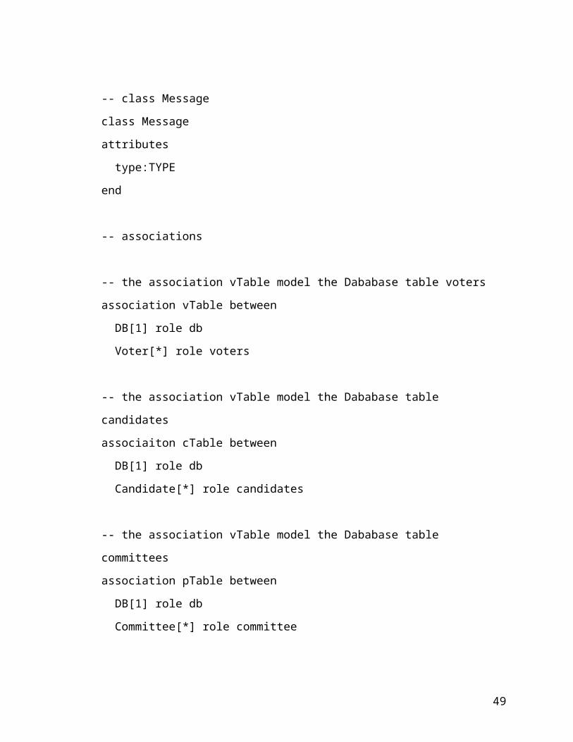
-- class Message
class Message
attributes
type:TYPE
end
-- associations
-- the association vTable model the Dababase table voters
association vTable between
DB[1] role db
34

Voter[*] role voters
-- the association vTable model the Dababase table candidates
associaiton cTable between
DB[1] role db
Candidate[*] role candidates
-- the association vTable model the Dababase table committees
association pTable between
DB[1] role db
Committee[*] role committee
association dbConnection between
DB[1] role db
ConClient[*] role client
association candidancy between
Ballot[1..*] role ballot
Candidate[1..*] role cands
association writein between
Ballot[1..*] role ballot
Candidate[*] role writein
association oneToOneLinkage
DB[1] role db
IVMS[1] role manager
association acceptconnection between
Server[1] role server
ConClient[*] role con
35

-- a voter may have many sessions
association session between
Voter[1] role voter
VClient[*] role logon
end
association logon between
VClient[1] role patron
ConClient[1] role receiper
association admin between
Administrator[1] role manager
IVSM[1] role system
end
association service between
Server[1] role server
IVSM[1] role system
end
association belongsTo between
Candidate[1..*] role cands
Committee[1] role com
end
association castballot between
Ballot[1] role ballot
VClient[1] role voter
36

--constraints
constraints
context DB
-- the system only maintain one db
inv oneDB
DB.allInstances->size() = 1
context Administrator::VerifyPassword(psword : String) : Boolean
pre:self.password.isdefined
post:result = self.password.equals(psword)
context Voter
-- Voter ID can't be same
inv nosamevoterid:
Voter.allInstances->forAll(v1,v2:Voter|v1<>v2 implies (v1.id <> v2.id));
-- Every vote can only vote one time
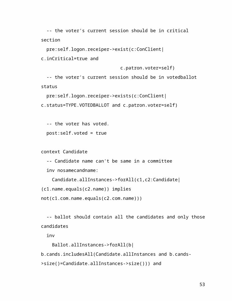
context Voter::vote()
-- the voter did not vote yet
pre:self.voted = false
-- the voter's current session should be in critical section
pre:self.logon.receiper->exist(c:ConClient|c.inCritical=true and
c.patron.voter=self)
-- the voter's current session should be in votedballot status
pre:self.logon.receiper->exists(c:ConClient|c.status=TYPE.VOTEDBALLOT and
c.patron.voter=self)
37

-- the voter has voted.
post:self.voted = true
context Candidate
-- Candidate name can't be same in a committee
inv nosamecandname:
Candidate.allInstances->forAll(c1,c2:Candidate|(c1.name.equals(c2.name)) implies
not(c1.com.name.equals(c2.com.name)))
-- ballot should contain all the candidates and only those candidates
inv
Ballot.allInstances->forAll(b|b.cands.includesAll(Candidate.allInstances and b.cands-
>size()=Candidate.allInstances->size())) and
Candidate.allInstances.includesAll(Ballot.allInstances.cands)
context Candidate::voted()
-- the ballot's holder should be in critical section
pre:self.ballot.voter.receiper->exist(c:ConClient|c.inCritical=true and
c.status = TYPE.VOTEDBALLOT and
c.patron.ballot.cands.includes(self))
post:self.votes = self.votes@pre+1
context Committee
-- Committee name can't be same
inv nosamecommittee:
Committee.allInstances->forAll(c1,c2:Committee|c1<>c2 implies
not(c1.name.equals(c2.name)))
-- Each committee should have at least candidates of number of the positions
38

inv numOfCandidates
Committee.allInstances->forAll(c:Committee|not(c.can->size() < c.position) and
c.can.forAll(cand:Candidate|
cand.comm.equals(c.name)))
context ConClient
-- only one conclient can be in critical section
inv oneconclientincritical
ConClient.allInstances->forAll(c1,c2:ConClient|(c1<>c2 and c1.inCritical=true)
implies c2.incritical = false
context ConClient::enterCritical()
-- no others are in critical section and it is in votedballot status
pre:ConClient.allInstances->forAll(c:ConClient|c.inCritical = false) and
self.status=TYPE.VOTEDBALLOT
-- it is safe to enter the critical section
post:self.inCritical=true
context ConClient::exitCritical()
-- done in critical, so exit
pre:self.inCritical=true
-- other may enter the critical section
post:self.inCritical=false
context IVSM
-- Over time must be greater than Start time
inv overtimeGreaterthanstart:
self.startTime < self.overTime
context Server::run()
-- Only after the start time does server begin
39
pre:self.system.startTime < self.currentTime
-- after the over time less than current time
post:self.system.overTime < self.currentTime
context Server::tick()
-- every time kick those inavtive conclient
post:self.con->forAll(c:ConClient|c.inactivity>self.MaxInactivity implies c.status =
TYPE.SHUTDOWN)
context Server
-- system is ready before it can accept the request
inv systemready:
self.connserver.isdefined() implies self.system.isdefined()
context VClient::run()
-- in starting status
pre:self.status = TYPE.INIT
-- in ending status
post:self.status = TYPE.SHUTDOWN
context Ballot
-- people voted in a ballot can't excess each committee positions
inv
Committee.allInstances->forAll(c:Committee|(self.cands->select(voted=true and
comm.equals(c.name)
)->size() +
self.writein->select(voted=true and
comm.equals(c.name)
)->size()) <= c.position
40

)
-- writein people can't have same name as in the same committee of a ballot
inv
Committee.allInstances->forAll(c:Committee|self.writein->select(
comm.equals(c.name)
)->forAll(
w:Candidate|
not self.cands->select(comm.equals(c.name))->forAll(
can:Candidate|
can.name.equals(w.name)
)
)
)
-- writein can't have the same name in one committee of a ballot
inv
Committee.allInstances->forAll(c:Committee|self.writein-
>select(comm.equals(c.name))->forAll(
c1,c2:Candidate|not c1.name.equals(c2.name)
)
---------------------------------------------------------------------------------------------------------
End of the specification
---------------------------------------------------------------------------------------------------------
Section 8
41

Formal Technical Inspection
8.1 Introduction
A formal technical inspection or formal technical review (FTR) is a software quality
assurance activity. The purpose of FTR is to find and eliminate defects. It can be applied
to any product or partial product of the software development process, including
requirements, designs, and code. The formal technical inspections are embedded in the
process of developing products and are done in the early stages of each product’s
development.
In this document, the system design will be subjected to the formal technical inspection.
Some formal checklists will be developed and used to inspect the all aspects of the
software development. This document contains a checklist for the SRS Documents, a
checklist for design, a checklist for OCL specification.
8.2 Reference
NASA Software Formal Inspections Guidebook
http://www.gsfc.nasa.gov/fi/gdb/fi.ps
8.3 Software requirement specification checklist
Completeness
Does SRS include all user requirements (as defined in the concept phase)?
Yes.
Do the functional requirements cover all abnormal situations?
N/A.
Have the temporal aspects of all functions been considered?
No.
Does SRS define those requirements for which future changes are anticipated?
No.
Are the environmental conditions specified for all operating modes (e.g., normal,
abnormal, disturbed)?
No.
42

Consistency
Is there any internal inconsistency between the software requirements?
No.
Does SRS use standard terminology and definitions throughout?
Yes.
Is SRS compatible with the operational environment of the hardware and
software?
N/A
Has the impact of software on the system and environment been specified?
N/A.
Has the impact of the environment on the software been specified?
N/A.
Correctness
Does the SRS conform to SRS standards?
Yes.
Does the SRS identify external interfaces in terms of input and output
mathematical variables?
N/A.
Is there justification for the design/implementation constraints?
Yes.
Feasibility
Will the design, operation, and maintenance of software be feasible?
Yes.
Modifiability
Are requirements organized to allow for modifications?
Yes.
43

Is each unique requirement defined more than once? Are there any redundant
statements?
No.
Traceability
Does the SRS show explicitly the mapping and complete coverage of relevant
requirements and design constraints defined in the concept phase?
Yes.
Is SRS traceable forward through successive development phases (e.g., into the
design, code, and test documentation)?
Yes.
Understandability
Is the language ambiguous?
No.
Does the SRS contain only necessary implementation details and no unnecessary
details?
Yes.
Is the SRS over specified?
No.
Are the requirements clear and specific enough to be the basis for detailed design
specs and functional test cases?
Yes.
Maintainability
Does the documentation follow MSE portfolio?
Yes
Is the documentation clear and unambiguous?
Yes
44

Verifiability/Testability
Are the requirements verifiable (i.e., can the software be checked to see whether
requirements have been fulfilled)?
Yes.
8.4 Software design checklist
Is each class a good abstraction?
Yes
Does each class have high cohesive?
Yes
Is there low coupling?
Yes
Is each function limited to necessary knowledge?
Yes
8.5 OCL checklist
Is the syntax of each expression correct?
Yes
For each operation, is it applied to an instance of the correct type?
Yes
For each equality, do the expressions on each side resolve to the same type?
Yes
Section 9
45

Object Model
9.1 Object model of Internet Voting System Manager
IVSM
admin : Administrator[]server : Serverquery : QueryWrappersDate : DateeDate : Date
verifyID(id : Sring, passwd : String) : booleansetVoters(voterDataAddr : String) : voidgetVoters() : StringsetCandidates(canddAddr : String) : voidgetCandidates() : StringsetStartDate(date : Date) : DatesetEndDate(date : Date) : DateisVotingOver() : boolean
ConnectionPoolcheckedOut : intfreeConnections : VectormaxConn : intname : Stringpassword : StringURL : Stringuser : String
freeConnections()getConnection()getConnection()release()newConnection()
Candidatevoted : booleanname : String
getName()setName()voted()isVoted()
ConnServertimeOfLastActivity : longstatus : Integerkey : String
run()
ConnManagerconn : ConnectionPoolquery : QueryWrapperinstance : ConnManagerclients : intdrivers : Vectorpools : Hashtablelog : PrintWriter
freeConnection()getConnection()getConnection()getInstance()release()
QueryWrapperconnManager : ConnManager
init()insertVoters()insertCandidates()confirmVoter()votingResult()sendingResult()pwdRequest()getBallot()addVotes()
BallotvotingGuide : Stringtitle : Stringissuer : Stringsubject : Stringdate : DatevoteID : Stringcommittee : String[]candidate : string[][]num : int[]newCand : String[][]
setCommittee()setCandidate()voteCandidate()voteNewCandidate()
Ticker
run()
TriggerServerwarning_if_inactive : inttime_to_close_a_warnreaper_time : intmaxinactivetimeparticipants : Hashtableticker : Ticker
run()getBallot()tick()
MailSenderhost : Stringid : Stringaccound : Stringfrom : String
singleMailSent()batchMailSent()
Administratorid : Stringpassword : String
setPassword(passwd : String) : voidgetID() : StringgetPassword() : StringverifyID(id : String) : booleanverifyPassword(passwd : String) : boolean
Figure 9: Object Model of IVS Manager - Server Side
9.2 Object Model of Internet Voting System Client
46

VClientintroFrame : IntroFramelogonFrame : LogonScreenvotingFrame : VotingScreenstatusFrame : ProgressScreencomm : ConnClient
BallotsetCommittee : voidsetCandidatevoteCandidatevoteNewCandidate
setCommittee()setCandidate()voteCandidate()voteNewCandidate()
ConnClient
run()
TimeroutThreadthreadStatus : boolean
stopThread()run()
Candidatevoted : Booleanname : String
setName()getName()Voted()isVoted()
Figure 10: Object Model of IVS Manager – Client Side
9.3 Interactive diagram of Server side:
47

ivsm : IVSM administrator : Administrator
server : Server connServer : ConnServer
Handler : ServerProtocol
wrapper : QueryWrapper
connManager : ConnManager
setCandidates(String)
verifyPassword(String)
setStartAndOverTime()
setDatabase(String)accept( )
start( ) xmlProcess(String)
verifiedQuery(String)
ballotQuery(String)
getConnection(String)
verifiedQuery(String)
ballotQuery(String)
accept( )
Figure 11: Interactive diagram of IVS Manager – Server Side
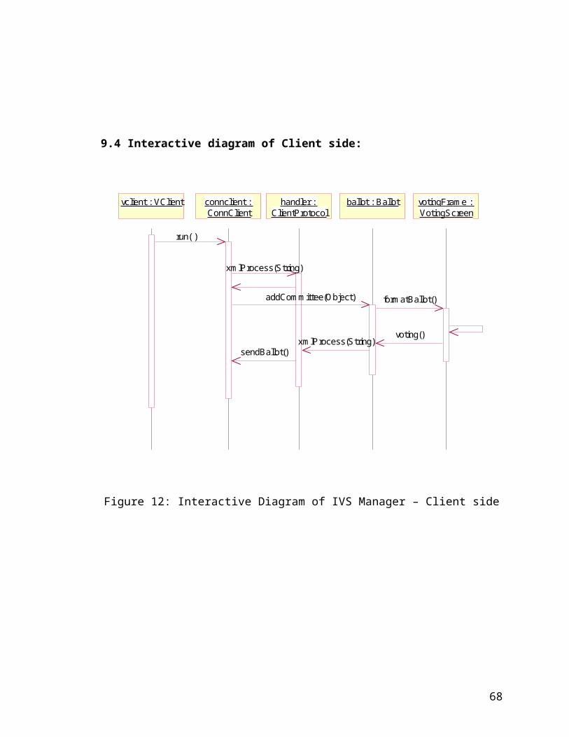
9.4 Interactive diagram of Client side:
48
vclient : VClient connclient : ConnClient
handler : ClientProtocol
ballot : Ballot votingFrame : VotingScreen
run( )
xmlProcess(String)
addCommittee(Object) formatBallot()
voting()xmlProcess(String)
sendBallot()
Figure 12: Interactive Diagram of IVS Manager – Client side
Section 10
49

Test Plan
10.1 Identifier
N/A
10.2 Introduction
The Software Test Plan (STP) describes plans for qualification testing of Server
side and client side components in IVSM (Internet Voting System MAnager) project.
The purpose of the test plan should be able to ensure that intended functionality is being
implemented properly in each module of the code. To fulfill this objective, a series of test
will be executed during the coding.
10.3 Scope
This test plan outlines the strategies on unit testing and integration testing. Unit
testing focuses verification effort on the major functions, and integration testing tests
the program structures built with unit-tested modules.
10.4 Approach
Unit testing: each class is tested separately. The testing is focused on the major
functions in each class. White box and black box techniques are both used.
Integration testing: For the Client and Server components, we want to test their
performance together with other components, such as Database and main window.
Stress testing and boundary testing will be used.
10.5 Test Cases
After a user enters the homepage of the program at client side, a friendly GUI
interface will show up with introducing of voting. Test whether the main window
appear properly
After a user press OK button in the introducing frame, a friendly GUI interface
will show up with asking for the inputs for user name and password. Test
whether the main window appear properly.
50

After the user inputs correctly, another widow will show up with the connection
status. Test whether the program can handle the correct inputs and other
exceptions.
At this point, If the client connects to the server correctly, the ballot will show up.
The user can cast the ballot now. Test whether the components has the correct
functionalities.
If the voter press send_the_ballot button, Test whether all functionalities have the
expected responses.
System has robust error handler. By given malicious input, the system will detect
its invalid, give error message and logging on it.
Stress testing, in a short time, a lot of clients will try to connect to the server,
testing if the server can handle it.
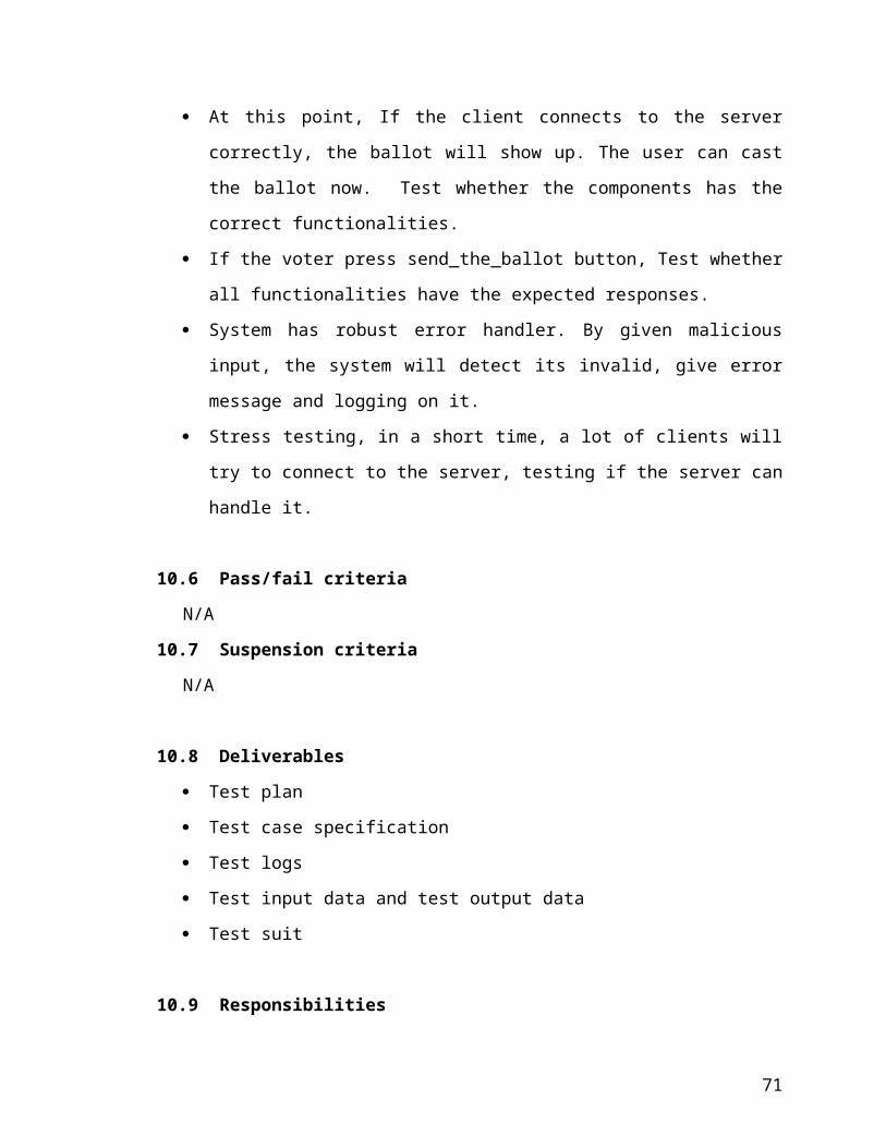
10.6 Pass/fail criteria
N/A
10.7 Suspension criteria
N/A
10.8 Deliverables
Test plan
Test case specification
Test logs
Test input data and test output data
Test suit
10.9 Responsibilities
The developer is responsible for all the testing activities to be carried out.
10.10 Schedule
Unit testing – each unit will be tested during implementation.
51

Integration testing – The program is constructed and tested in small segments
after all functions are finished and unit tested.
10.11 Contingency Plans
N/A
10.12 Approvals
Approved by Committee members.
Section 11
Time log for Phase Two
52
Date Start Stop Time Activity Comment
10/22/01 10:00 10:30 0.5 hr Reading rules, design Start
10/24/01 10:30 12:00 1.5 hrs Reading materials,
learning Formal Spec
10/28/01 2:00 6:00 4 hrs Design List required item
10/30/01 1:30 6:00 4.5 hrs Object model Add more details
11/1/01 8:30 12:00 3.5 hrs Object model Add more details
11/4/01 2:00 5.30 3.5 hrs Object model Add more details
11/9/01 8:30 10:30 2 hrs Write design document
11/10/01 11:00 2:00 3 hrs Formal specification
11/12/01 2:00 6:00 4 hrs Formal specification Modify
11/15/01 8:00 12:00 4 hrs SQA plan
11/18/01 7:00 11:00 4 hrs SQA plan Modify
11/22/01 3:00 7:00 4 hrs Formal specification Modify
11/23/01 8:00 10:00 2 hrs Test plan
11/25/01 8:00 11:30 3.5 hrs Test plan
11/28/01 2:30 5:30 3 hrs Test plan
12/5/01 2:00 6:00 4 hrs Formal technique
review
12/6/01 9:00 12:00 3 hrs Formal technique
review
12/13/01 2:00 6:00 3 hrs Formal specification Modify
12/14/01 8:00 12:00 4 hrs Formal specification Modify
1/17/02 7:00 11:00 4 hrs Modify object model
1/22/02 8:00 11:00 3 hrs Modify object model
1/24/02 3:00 3:30 0.5 hrs Meet with Dr. Bleyberg
2/2/02 8:00 12:00 4 hrs Formal specification Modify
2/9/02 2:00 6:00 4 hrs Modify object model
2/16/02 2:00 6:00 4 hrs Formal specification Modify
53

2/23/02 2:00 6:00 4 hrs Formal specification Modify
3/1/02 11:30 4:00 4.5 hrs Review Check document in
Phase I
3/7/02 8:00 12:00 4 hrs Write document
3/14/02 2:00 6:00 4 hrs Prepare for
presentation
Make slides
3/28/02 2:30 3:30 1.0 hrs Presentation Two
Part Three
54

Phase III Project Implementation
Section 12
Administrator Manual12.1 System requirement
Communication will be done using TCP/IP sockets. This requires that each
machine participating in the computation must be connected to the network.
Sun’s Java Runtime Environment, version 1.2 or higher must be installed in the
system.
Oracle DBMS 8i or other database must be installed.
The compiled source code is available in the following download site
(ftp://129.130.11.77/mseserver.jar).
12.2 How to install the Internet Voting System Manager – server side
a. Download the package mseserver.jar from ftp://129.130.11.77/mseserver.jar;
b. un-jar the mseserver.jar to destination directory;
c. change directory to the destination directory;
d. issue “runserver”
12.3 How to configure the Internet Voting System Manager – server side
a. After starting the system, first a welcome screen will appear. It will show up for
about 4 seconds.
Figure 13: Welcome Screen of IVMS
b. Set up the administrator
55

Then an administrator input dialog appears. The user should input the
administrator ID and password. The system will use the administrator ID to generate the
key for the whole system.
Figure 14: Administrator Input Dialog
c. IVS Manager main window
After inputting the administrator name and password, IVS Manager main window
comes. There is a menu bar in the main window which includes Election, Server, Result,
Admin and Help menus and a text display screen.
Figure 15: The Main Window for Configure the IVMS
d. Make Keys and Init DB
56

In main window, by selecting the election menu and clicking the Make Keys and
Init DB, user should select a database properties file to make the keys and initialize the
database for the system.
Before the administrator can set the database properties, make sure the database is
available. The administrator can use any database. The following is an example of
db.properties for an Oracle database and JDBC driver.
The data format of db.properties:
jdbc.drivers=oracle.jdbc.driver.OracleDriver
jdbc.url=jdbc:oracle:thin:@zaurak.cis.ksu.edu:1521:PROD
jdbc.user=******
jdbc.password=*******
jdbc.maxconn=10
After initiating the database, the system will build three tables: Voters, Candidates and
Committees
Create Table Voters (
name VARCHAR(50),
code NUMBER,
email VARCHAR(50),
pwd VARCHAR(20),
voted CHAR(5)
)
Create Table Candidates (
name VARCHR(50),
committee VARCHAR(255),
votes NUMBER
)
Create Table Committees (
committee VARCHAR(255),
pnum NUMBER
)
e. Import voters and candidates
57

By selecting the election menu and clicking the Import Voters/Candidates, user
should select a voters.dat/candidates.dat file to populate the voters/candidates/committees
table.
The data format of voters.dat:
Yonghua Li, 1, [email protected]
Maria Bleyberg, 2, [email protected]
William Hsu, 3, [email protected]
David Gustafson, 4, [email protected]
Table 9: The Voters Table in DB
Name Id email pwd voted
Yonghua Li 1 [email protected] **** no
The system will generate a password for each voter and set the voted to “no”.
The data format of candidates.dat:
Committee:CITY OFFICES MANHATTAN CITY COMMISSIONERS
Position number:3
Carol Peak
Roger P. Reitz
Mark Taussig
Brad Everett
David L. Johnson
Karen McCulloh
Committee: USD #383 SCHOOL BOARD MEMBER
Position number:3
Jim Shroyer
J. Scott Smith
Dorothy Soldan
Milo Kelly
Walter Pesaresi
Flordie Pettis
58
Table 10: The Candidates Table in DB
Name Committee votes
Carol Peak CITY OFFICES MANHATTAN 0
…… …… ……
The system will set the votes to 0.
Table 11: The Committees Table in DB
Committee Pnum
CITY OFFICES MANHATTAN 3
#383 SCHOOL BOARD MEMBER 3
f. Start the IVS Server
By selecting the server menu and clicking the Start Election Time, set the election
starting time. Then set the election ending time. After the election time has been set up,
the server can be start by selecting the server menu and clicking start server.
g. Set the mailSender
By selecting the result menu and clicking the outMailServer, set the mail server and
account.
Figure 16: The Dialog for Setup the Mail Server
h. Hiding the main screen.
59
By selecting the Admin menu and clicking the Log Off, the main windows can be hidden.
Then only the administrator can log on this system by inputting the administrator ID and
password set at the system starting.
12.4 How to install the Internet Voting System Manager - client side
a. Download the package mseclient.jar from ftp://129.130.11.77/mseclient.jar
b. un-jar the mseclient.jar to the destination directory.
c. Change directory to destination directory.
c. issue “runclient”. A flash screen appears for about 4 seconds, then come with
the IVS Client main windows. The voter can vote through this screen.
Section 13
60

Voter Manual
13.1 Overview
The client main GUI has a display screen and two buttons: Enter to Voter and Password
Request.
Figure 17: The Main GUI for IVMS - Client
13.2 Request Password
If the voter presses the Password Request button, the password request GUI will show.
The password request GUI has two text boxes for inputting the voter name, voter ID. The
requested password will be send to the voter’s email account if data voter enters are
correct and press Send button. If Exit button has been pressed, the system will return to
the client main windows
61

Figure 18: Password Request GUI
13.3 Vote
a. Log on
If the voter presses the Enter Vote button, the confirmation screen shows. The
confirmation screen has three text boxes and two buttons. Fill the boxes and press the
send, if confirmed, press vote button in the next windows to cast the ballot.
Figure 19: Confirmation GUI
b cast ballot
62
The voting ballot screen: each committee is listed as a column. According to the
instruction in the ballot, cast the ballot and press the Vote button. If successfully, return
to the main windows. If not, a wrong message shows, and voter can try again.
Figure 20: The Ballot GUI
63

Section 14
Test and Reliable Evaluation
14.1 Overview
The testing of Internet Voting Manager System (IVMS) was performed on CIS UNIX,
Win-XP machine and Linux machine. The test plan of phase2 was followed to conduct
the testing of the system. Besides testing the correctness of the tool, we also tested its
performance. Correctness test includes unit tests, integration tests, system test. On the
other hand, performance tests were tested by stress testing.
14.2 Unit and Integration test
The internet voting management system consists of two parts: the server side components
and client side components. The server side components includes internet voting system
manager component, database connection and query manager component, the server and
client connection component and mail sender component and client component. The
black box random testing and regression testing are adopted in integration testing.
The following testing technologies are adopted in component unit testing. For each
component, the functional testing, white box testing and/or black box testing, has been
used. In white box testing, path-based domain testing and/or boundary testing are used to
generate test cases. In black box testing, random testing and/or regression testing are used
to generate test case.
The percentage of test result will be used decide to if the software passes or fails. If the
test cases passing rate is greater than 90%, the component passes the testing. If the test
cases passing rate is less than 70%, the component fails in this test. If the rate is among
70 ~ 90%, more test cases are used.
A test bed was written for testing. In this test GUI system, menu bar has three menus,
Action menu, Kiosk Server Tests menu and Poll Server Tests menu. The following is the
snapshot of test bed.
64

Figure 19 Test Bed GUI
14.3 Test Log for Unit Testing and Integration Testing
Table 12: Test Log for Unit Testing
Component Testing method Functionality performance pass
DBConnectionPool Path-based
domain
getConnection,
freeConnection
Work well yes
DBConnectionManager Path-based
domain
getConnection,
freeConnection
Work well yes
DBQueryWrapper Path-based
domain
Boundary
Init()
importVoter
importCandidate
confirmVoter
votingResult
sendingResult
pwdRequest
getBallot
addVoter
Work well yes
IVMSManager Path-based actionPerformed Work well yes
65

domain
boundary
IVMSServer Path-based
domain
Tick
accept
Work well yes
ConClient Path-based
domain
Run Work well yes
MailSender Path-based
domain
singleMailSent
batchMailSent
Work well yes
IVMSClient Path-based
domain
boundary
actonPerformed Work well yes
Table 13: Test Log for Integration Testing
Integration Testing method Passing rate
DBManager-DBPool Regression, random 100%
DBWrapper-DBManager Regression, random 100%
ConClient-DBManager Regression, random 100%
mailSender-DBWrapper Regression, random 100%
14.4 System/Performance test
For system/performance testing, the following testing method are used.
All the GUI input box are tested by boundary testing. The client, server and DB
component are tested by stress testing to check the performance. Errors are injected in the
system to check if the system can catch all the errors. Stamp testing are used to check the
time between the client and server, server and DB. Error handling testing are used to
check the system robotics.
66

Table 14: Test Log for System/Performance Test
Testing type Functionality Performance pass
Boundary System Works well yes
Stress System Works well yes
Error injection System Catch all yes
Stamp System Works well yes
Error handling System Works well yes
14.5 Error-handling test
The following is the list used to Error handling testing.
Table 15: Test Log for Error-handling Test
Test items result
IVSManager can check if the db.properties is correctly file pass
IVSManager can check if the voter.dat file is correctly file Pass
IVSManager can check if the candidate.properties is correctly file pass
IVSManager can check if the election start time is correct Pass
IVSManager can check if the end time is correct Pass
IVSManager can check if the server port is ok pass
IVSManager can check if the mail sender server is right pass
IVSClient can check if the pwd request input boxes are filled pass
IVSClient can check if the confirm input boxes are filled pass
IVSClient can check if the ballot cast number is right pass
IVSClient can check if the new candidate is clicked and filled pass
14.6 Fairness and Integrity test
Fairness is one of the most important factors for a successful voting. For each candidate,
the probability of election should not be affected by the placement of candidate on the
ballot. So each candidate should have the same probability to appear on any place this
group of candidates could appear.
67
This following table is the result which put the candidates of one committee in the first
place. The probability of candidate appeared on other place is distributed totally same.
The total ballots is 10000. From the result we can see, it is pretty fair for each candidate.
Table16: Fairness Test
Candidate Count probability
Candidate 1 1662 16.62%
Candidate 2 1656 16.56%
Candidate 3 1673 16.73%
Candidate 4 1666 16.66%
Candidate 5 1671 16.71%
Candidate 6 1670 16.70%
The integrity is another most important factor in election. In this project, the voter should
not vote twice, and the voter’s ballot should not be lost.
Table 17: Integrity Test result
Test Item Performance pass
case for voting twice Works well yes
case for log on multi place Works well yes
case for losing ballot Works well yes
14.7 Conclusion
At this time, this project provides a reliable running program with satisfied result. Further
fairness and integrity are possible but beyond this project.
68

Section 15
Project Evaluation
15.1 Overview of the software development life cycle
I applied the most widely used software development life cycle model (Waterfall model)
to develop my MSE project. Waterfall model consists of five stages: (1). Requirement
specification; (2) software design; (3) code generation; (4).Testing and integration; (5).
Maintenance. My MSE project development process includes three phases: (1).
requirement specification phase, (2). design phase, and (3). implementation phase. These
three phases covered all stages in the waterfall model. Each development phase was well
documented, and all documents were reviewed by the committee members. New phase
was started after completion of the previous phase. More important, after each phase,
review and formal inspection was done. In the implementing phase, unit and integration
test were performed to assure quality of the software.
15.2 Evaluation of phase1
Phase one focuses on the requirement of the software development. This stage is based
on the discussion with Professor Bleyberg to make the requirements clear. After a
reasonable understanding is achieved, a basic idea and a preliminary design have been
formed that benefits the further understanding of the requirements. With this
understanding, next steps are to gather and specify the requirements of the project,
including background review, project overview, software requirement specification
(SRS), cost estimate and project plan. Some figure is also made to describe the system
configuration.
The SRS is the central task in this phase, it states the purpose of the tool, the expectation
of the potential user, and the functionality the tool will provide. When the project reaches
the final stage, it turned out that all the requirements specified in Phase 1 have been
achieved. I use the function positions to estimate the size of my product, use COCOMO
model to calculate the development time. The estimated size of my project is 5.1 kLOC.
The estimated development time of my project is 7.0 months. The actual size of my
project is 3.9 kLOC. The actual development time is 10 months. The actual size of code
69

is far less than the estimated value. This is understandable because java has a lot of
library packages which actual coding benefits from them for saving lines and time.
15.3 Evaluation of phase2
The major task in Phase II is to develop a detailed design guiding the implementation of
project. It includes object model, formal specification, SQA, test plan, and formal
technique inspection. The object model is the central task of this phase. The object model
outlines the overall software architecture of project.
It specifies what kinds of components consist of the whole project; what kinds of objects
constitute each component, what kinds of main methods is composed of each object. All
these design issues are very important for the implementation step. The raw idea formed
in Phase One is further developed in details, especially in the form of a computer
language (Java). The results of this make some changes with those object model roughly
designed in Phase One. To make the Phase One document consistent with the current
design requirement, the formal technique inspection has been performed in this phase.
After finishing the object model, we need to choose one formal specification language to
specify the project design. I choose UML/OCL to specify the object model of my project.
The formal specification specifies exactly what each object do, what each method of the
object do. The sequence diagram specified the call sequence of related methods. All this
information is very important fro the phase III. I use the tool USE version 2.0.0 to verify
the correction of my formal specification. Because this tool is a new tool, I spend one
week to study it, then I use it in my case.
The test plan, SQA plan, and formal inspection are also very important for software
design. With the test plan, I can improve the performance of my program by taking all
kinds of possibilities. The SQA plan gives me a guideline to make sure if the software
meets the all functionality requirements, technical requirements, and reliability
considerations. In the formal specification, committee member can gave me very helpful
suggestions.
70
15.4 Evaluation of phase3
Phase III of the project focus on the actual implementation and test of the tool. After
understanding the requirement properly and designing the project efficiently, the coding
was going smoothly for major functions. At first, I modified and developed the
DBConnectionManager component, and wrote a small application program to use the
DBConnectionManager component to connect the dababase. Secondly, I developed an
IVMSManager component, and wrote a small program to run this IVMSManager
component, which configure the system. Thirdly, I implemented the server component
class to handle all the clients logging on. Fourthly, I wrote the client component through
which voters can cast the ballots. Finally, I put these three components together to make
the whole system run.
In this phase, testing is also finished. Basically, this task is performed simultaneously
while coding. When the coding reaches the end, the system test and integration test are
performed using the test case designed in Phase II. At least, the test report has been
provided as in the above section. Refer to Section 14 for details.
15.5 Conclusion
The project is finished successfully according to the software requirement specification in
the Phase I. It was a great experience for me to complete such a parallel and distributed
computation project in a professional style. Working on the project not only gives me a
good understanding of software life cycle, but also gives me a chance to learn scientific
programming, framework implementation. I believe the whole process will make me a
better professional in this fascinating field.
71

Section 16
Time Log for Phase III
Date Start Stop Time Activity Comments
4/1/02 10:00 4:30 6.5 hrs Download java.mail
package and practice
Learning new thing is
time-consumed.
6:30 11:30 5 hrs Run examples
4/5/02 10:00 2:30 4.5 hrs Write simple test
application
Get everything work
4/8/02 7:00 11:00 4 hrs Coding some class for
the IVMS manager
component
Looks everything OK
4/12/02 10:00 4:00 5 hrs Writing server side
component
7:00 12:30 5.5 hr Redesigned some
helper class for the
task
4/20/02 10:30 5:00 6.5 hrs Coding client side
component
Meet a problem:
object input and
output stream in
network connection
6:00 12:00 6 hr Read material, study
Java API
Solving the problem
4/29/02 12:00 9:00 9 hrs Coding and debugging
Testbed component
5/4/02 8:00 10:00 14 hrs System Testing
5/12/02 8:00 11:00 3 hrs Continue testing Fix some bugs
9/1/02 7:00 11:30 4.5 hrs Testing in Unix
9/5/02 10:00 3:30 5.5 hrs Testing in Linux
9/12/02 7:00 11:00 4 hrs Coding the framework
72

for other components
9/13/02 10:00 4:00 6 hrs Try the Unix platform
to Windows
Class not found
problem
9/14/02 7:00 11:00 4 hrs Search web for help No clues
9/15/02 7:00 9:00 2 hrs Asking help from
System administrator
No clues
9/16/02 6:00 11:00 5 hrs Search web for help Found a paper and
solve the problem
9/20/02 7:00 10:00 3 hrs Try Linux platform to
Windows, Unix to
Linux
OK
9/26/02 9:00 11:30 2.5 hrs Writing documents
9/27/02 2:00 5:00 3 hrs Testing the project
9/28/02 10:00 4:00 6 hrs Testing the project Testing OK
10/1/02 8:30 11:30 3 hrs Writing documents
10/2/02 11:30 2:00 2.5 hr Writing testing report
10/3/02 7:00 10:00 3 hrs Writing documents
10/4/02 6:00 11:00 5 hrs Writing documents
10/5/02 2:30 6:30 4 hrs Prepare slides
10/14/02 2:30 3:30 1 hrs Pre - presentation Need to update the
web, some changes
are required
10/15/02 7:00 11:00 4 hrs Modify code to give
more popup dialoge
message, change the
candidate.dat format
10/16/02 6:00 10:00 4 hrs Edit final report
10/20/02 6:00 11:00 5 hrs Review final report
10/28/02 2:30 3:30 1 hr Final presentation
73

Appendix
Source Code
Final Report Document
Presentation Slides for Three Phases
74


![COCOMO-1 Only] [Compatibility Mode]](https://img.pdfslide.us/doc/110x75/577d27aa1a28ab4e1ea47e2f/cocomo-1-only-compatibility-mode.jpg)