Embed Size (px)
Citation preview

1
1/44
BEAM FORMINGBEAM-FORMING
2
Z A H R A N A G H S H
J U LY 2 0 0 9
2/44
CONTENT
Introduction
3
Smart antenna and SDRSeveral beam-forming methodsSeveral beam forming methodsAdaptive beam-forming algorithmssummerysummery
3/44
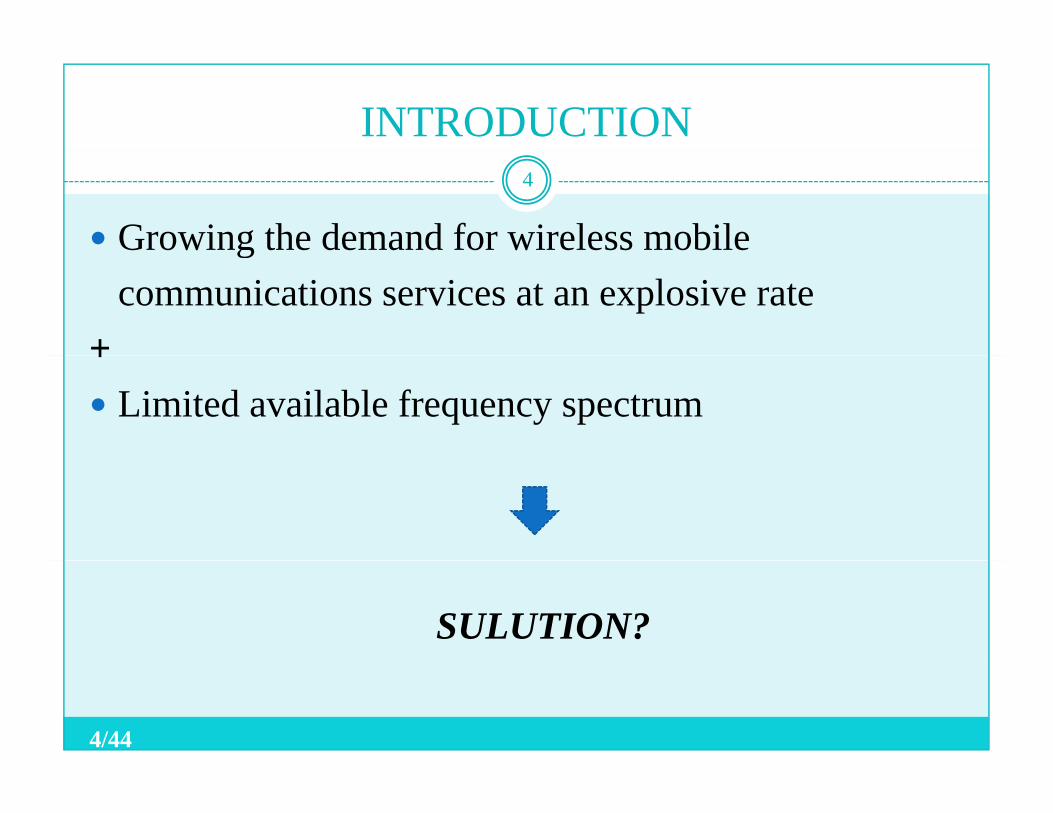
INTRODUCTION
Growing the demand for wireless mobile
4
gcommunications services at an explosive rate
++Limited available frequency spectrum
SULUTION?
4/44
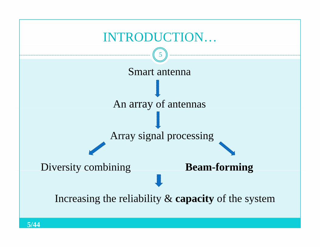
INTRODUCTION…
Smart antenna
5
An array of antennasy
Array signal processingay s g a p ocess g
Diversity combining Beam-formingDiversity combining Beam forming
Increasing the reliability & capacity of the systemIncreasing the reliability & capacity of the system
5/44
INTRODUCTION …
Smart the ability of the antenna
6
yto adapt itself to different signal environmentsthrough the use of different algorithmsthrough the use of different algorithms.
6/44
INTRODUCTION …
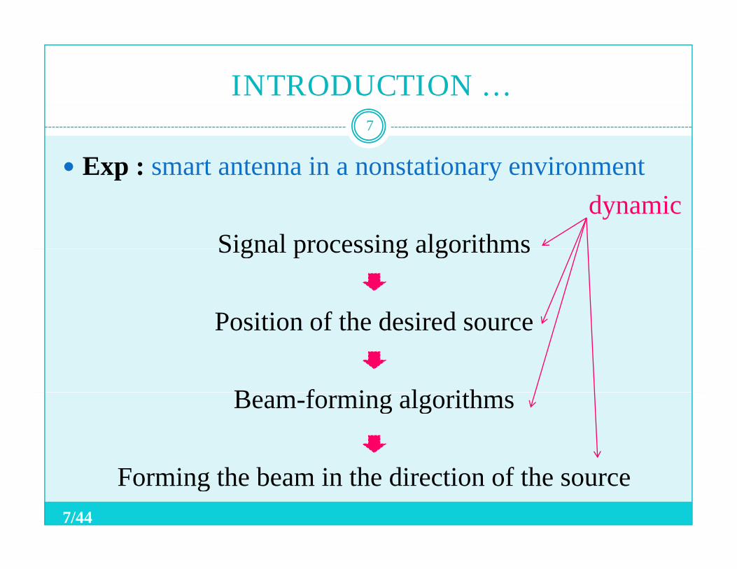
Exp : smart antenna in a nonstationary environment
7
p ydynamic
Signal processing algorithmsSignal processing algorithms
Position of the desired sourcePosition of the desired source
B f i l ithBeam-forming algorithms
Forming the beam in the direction of the source7/44
INTRODUCTION…
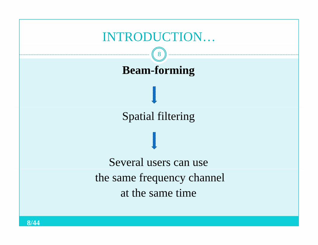
Beam-forming8
g
Spatial filtering
Several users can usethe same frequency channel
at the same time
8/44
INTRODUCTION…
Smart antenna was first used about 40 years ago
9
y gin RADAR applications.
The first issue ofThe first issue ofIEEE TRANSACTIONS ON ANTENNAS AND PROPAGATION bli h d i 1964PROPAGATION, published in 1964.
9/44
CONTENT
Introduction
10
Smart antenna and SDRSeveral beam-forming methodsSeveral beam forming methodsEssential signal-processing algorithmsAdaptive beam-forming algorithmsAdaptive beam forming algorithmssummery
10/44
SMART ANTENNA AND SDR
Smart antenna and SDR complement each other .11
p
• Smart antenna help software radio to adapt todifferent protocols, systems, channel conditions and … trough the use of signal processing algorithms toith bi th i d i l i tieither combine the received signals in an optimum
manner or beam-forming .
• Implementation of smart antenna algorithms require software and flexibility in hardware that is providedsoftware and flexibility in hardware that is providedby software radios.
11/44
CONTENT
Introduction
12
Smart antenna and SDRSeveral beam-forming methodsSeveral beam forming methodsEssential signal-processing algorithmsAdaptive beam-forming algorithmsAdaptive beam forming algorithmssummery
12/44
SEVERAL BEAM-FORMING METHODS
Terminology and signal model:13
Terminology and signal model:• An array of L omnidirectional elements in the far
field of M uncorrelated sinusoidal point sources offield of M uncorrelated sinusoidal point sources of frequency narrow band beam-forming 0f
• The time taken by a plane wave arriving from thei th source in direction and measured from the l th element to the origin is .
),( ii θϕ),( iil θϕτ
13/44
SEVERAL BEAM-FORMING METHODS14
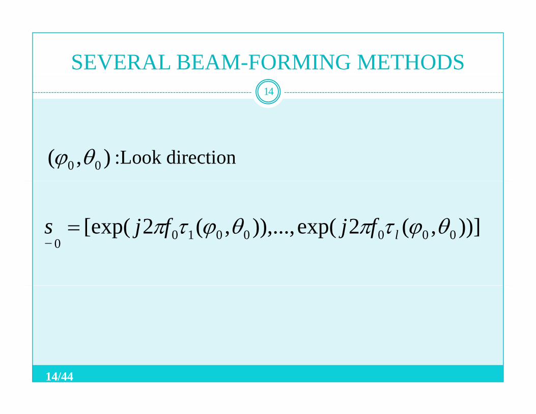
:Look direction),( 00 θϕ
))],(2exp()),...,,(2[exp( 0000010 θϕτπθϕτπ lfjfjs = ))],(2exp()),...,,(2[exp( 00000100
θϕτπθϕτπ lfjfjs−
14/44
15
SEVERAL
BEAM -FORMING
METHODSMETHODS…
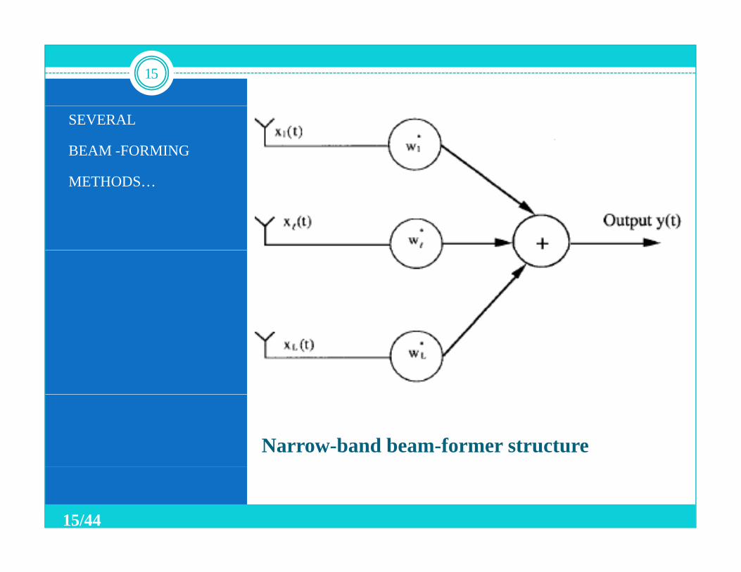
Narrow-band beam-former structure
15/44
SEVERAL BEAM-FORMING METHODS …
T
16
−=
T
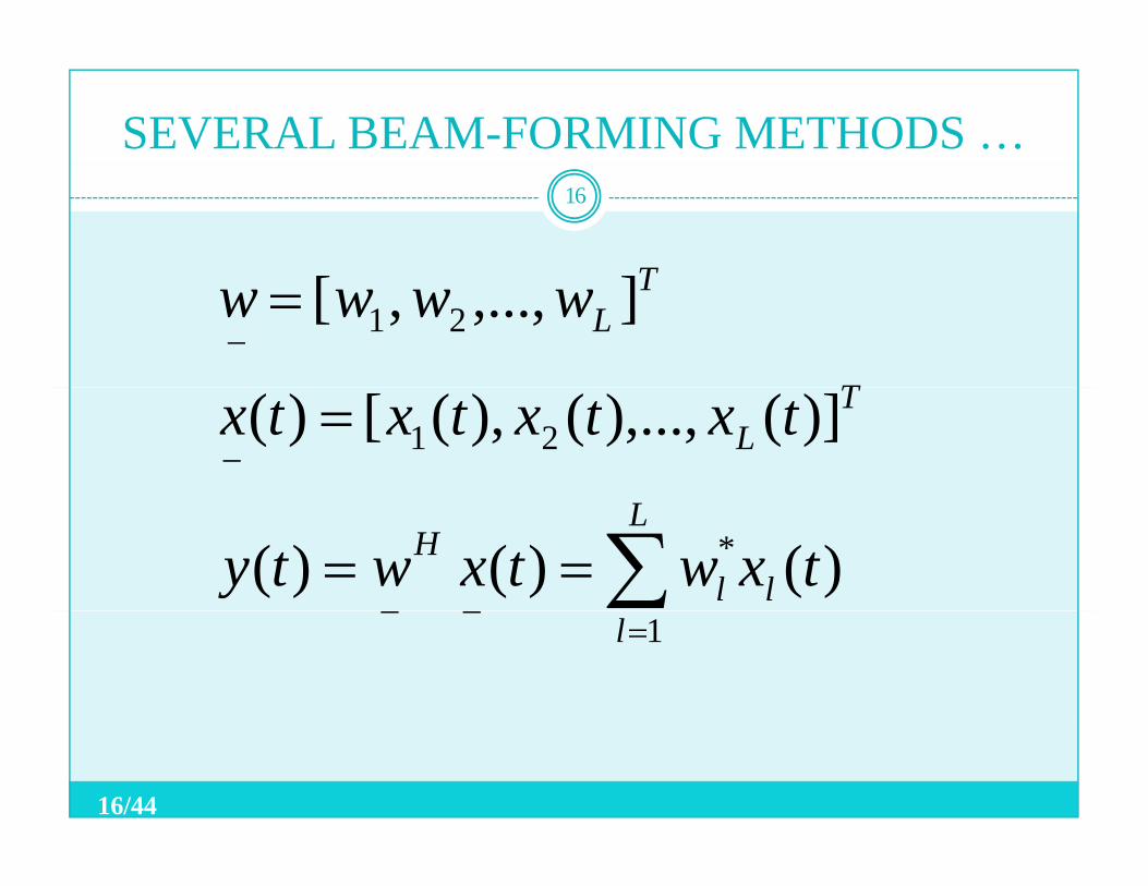
TLwwww 21 ],...,,[
−= T
L txtxtxtx 21 )](),...,(),([)(
∑==L
llH txwtxwty * )()()(
=−− l 1
16/44
SEVERAL BEAM-FORMING METHODS …
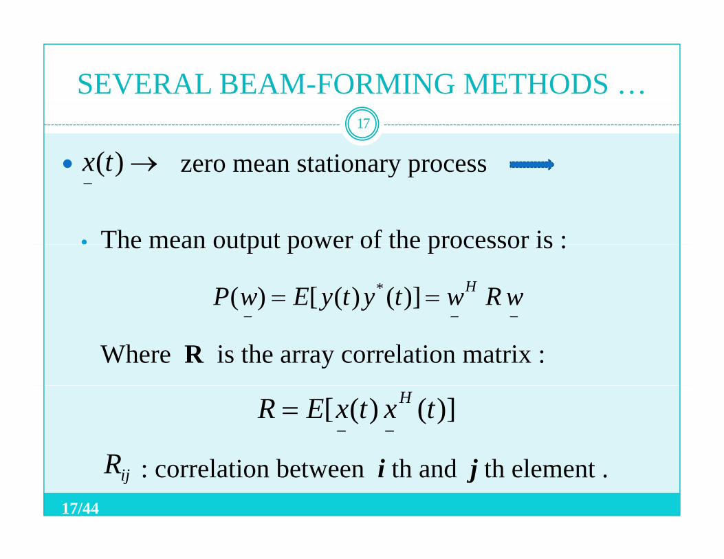
zero mean stationary process→)(tx17
y p
• The mean output power of the processor is :
−)(
The mean output power of the processor is :
== wRwtytyEwP H)]()([)( *
Where R is the array correlation matrix :−−−
)]()([ txtxER H
−−=
R : correlation between i th and j th element .ijR17/44
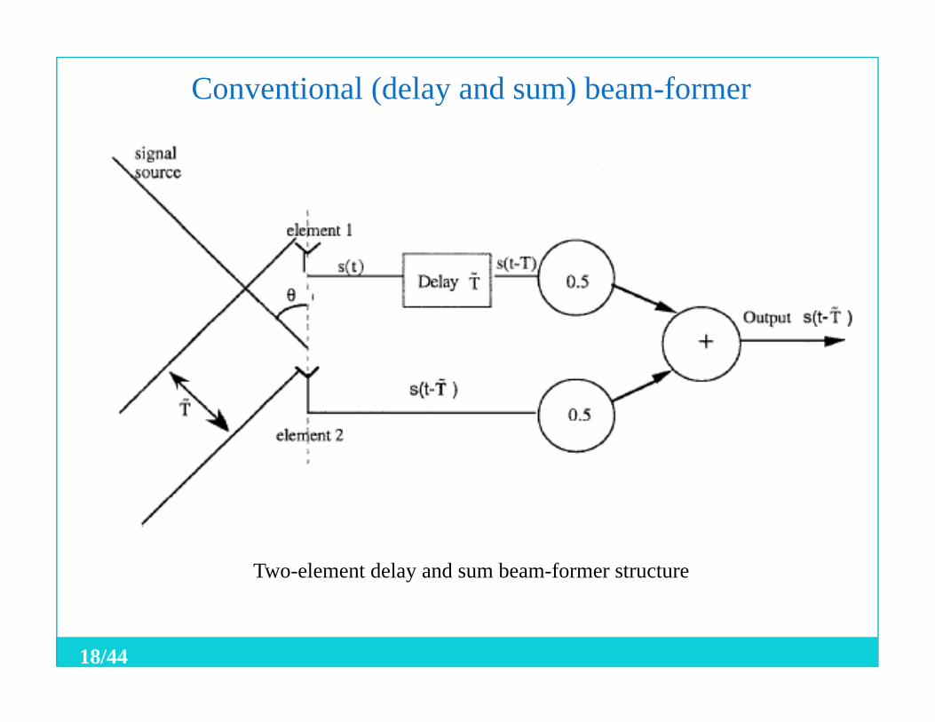
Conventional (delay and sum) beam-former
Two-element delay and sum beam-former structure
18/44
SEVERAL BEAM-FORMING METHODS …
Null-steering Beam-Former :19
Null steering Beam Former :• Goal :
Producing a null in the response pattern in aProducing a null in the response pattern in a response pattern in a known direction
Cancelling the plane wave arriving from thatdirection
19/44
SEVERAL BEAM-FORMING METHODS …
Limitations of null-steering beam-former :20
g
• It requires knowledge of the directions of interferers.
• It does not maximize the output SNR .
The optimal beam-forming overcome these limitations .
20/44
SEVERAL BEAM-FORMING METHODS …
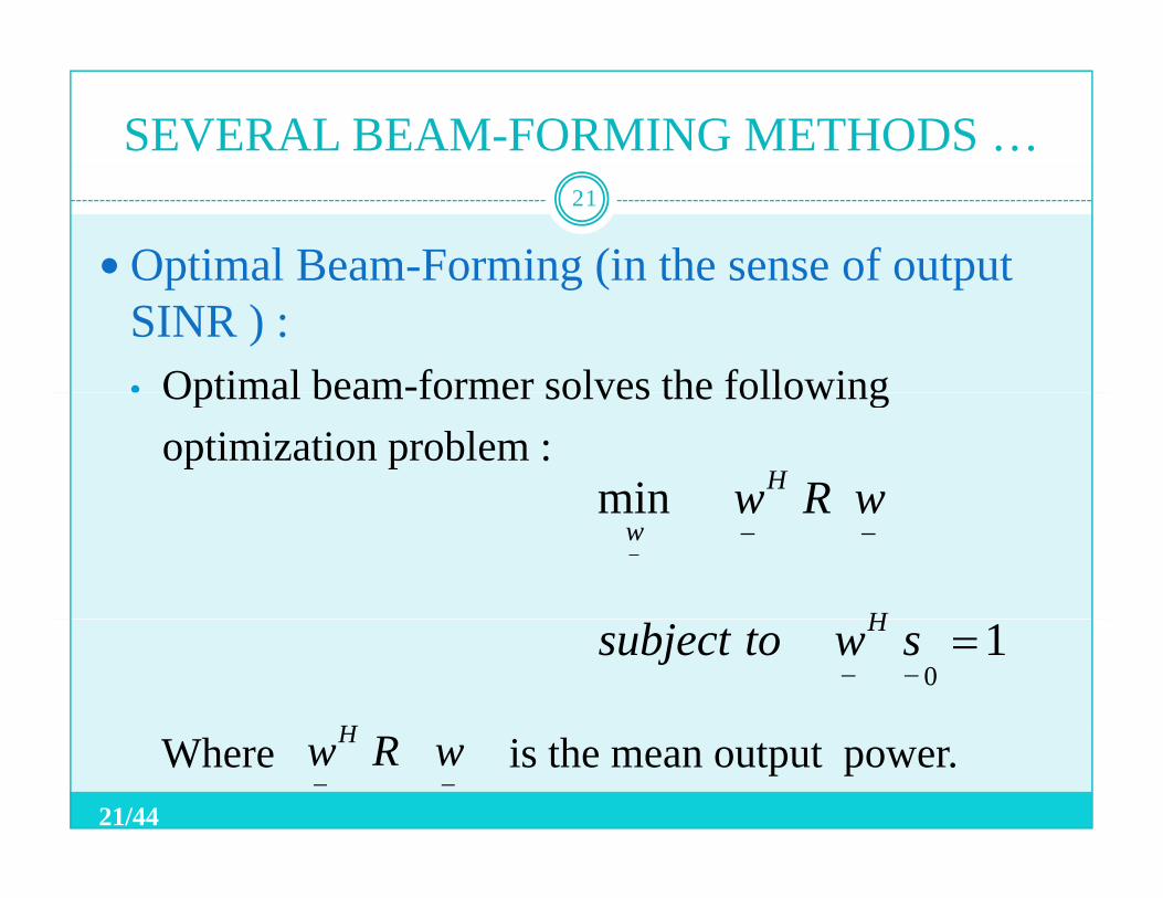
Optimal Beam-Forming (in the sense of output21
Optimal Beam Forming (in the sense of output SINR ) :• Optimal beam-former solves the followingOptimal beam former solves the following
optimization problem :min wRwHmin
−−−
wRw
H
w
10=
−−swtosubject H
HWhere is the mean output power.−−wRwH
21/44
SEVERAL BEAM-FORMING METHODS …
Minimizing the total output power while
22
g p pmaintaining the desired signal power in the output
equal to the desired source powerequal to the desired source power
Maximizing the output SINRMaximizing the output SINR
A i f f d ib l i th t t SNRAn increase of a few decibels in the output SNR can make a significant increase in the channel capacity of the system possible.
22/44
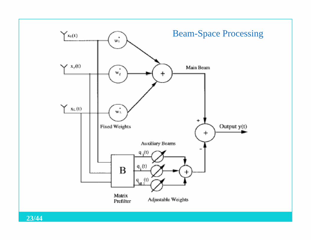
Beam-Space Processing
23/44
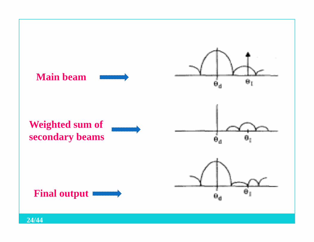
M i bMain beam
Weighted sum of secondary beamssecondary beams
Final output p
24/44
SEVERAL BEAM-FORMING METHODS …
Other beam-formers
25
• Broad- band beam-formers• Frequency-domain beam-formerq y• …
25/44
CONTENT
Introduction
26
Smart antenna and SDRSeveral beam-forming methodsSeveral beam forming methodsEssential signal-processing algorithmsAdaptive beam-forming algorithmsAdaptive beam forming algorithmssummery
26/44
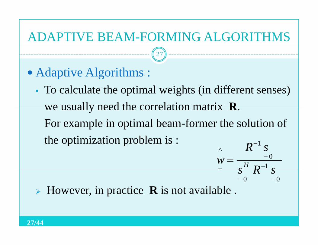
ADAPTIVE BEAM-FORMING ALGORITHMS
Adaptive Algorithms :27
Adaptive Algorithms :• To calculate the optimal weights (in different senses)
we usually need the correlation matrix Rwe usually need the correlation matrix R.For example in optimal beam-former the solution of th ti i ti bl ithe optimization problem is :
10
1^
−−
−
−=
sRs
sRw H
However, in practice R is not available .00 −−
− sRs
27/44
ADAPTIVE BEAM-FORMING ALGORITHMS …
The weights are adjusted using available
28
g j ginformation derived from the array output, arraysignals and so on to make an estimate of thesignals and so on to make an estimate of the optimal weights.
Th h h hi h llThere are many such schemes, which are normally referred to adaptive algorithms .
28/44
ADAPTIVE BEAM-FORMING ALGORITHMS …
LMS Algorithm (unconstrained) :29
LMS Algorithm (unconstrained) :• Reference signal :
For some applications enough may be known aboutFor some applications, enough may be known about the desired signal (arriving from the look direction )t t i t f i lto generate an appropriate reference signal.
The weights are chosen to minimize themean square error between the beam-former output and the reference signal.
29/44
ADAPTIVE BEAM-FORMING ALGORITHMS …
For example, if the desired signal is
30
p , gamplitude modulated, then acceptable performanceis often obtained by setting the reference signal equalis often obtained by setting the reference signal equalto the carrier.
In the unconstrained LMS algorithm reference signali dis used.
30/44
ADAPTIVE BEAM-FORMING ALGORITHMS …
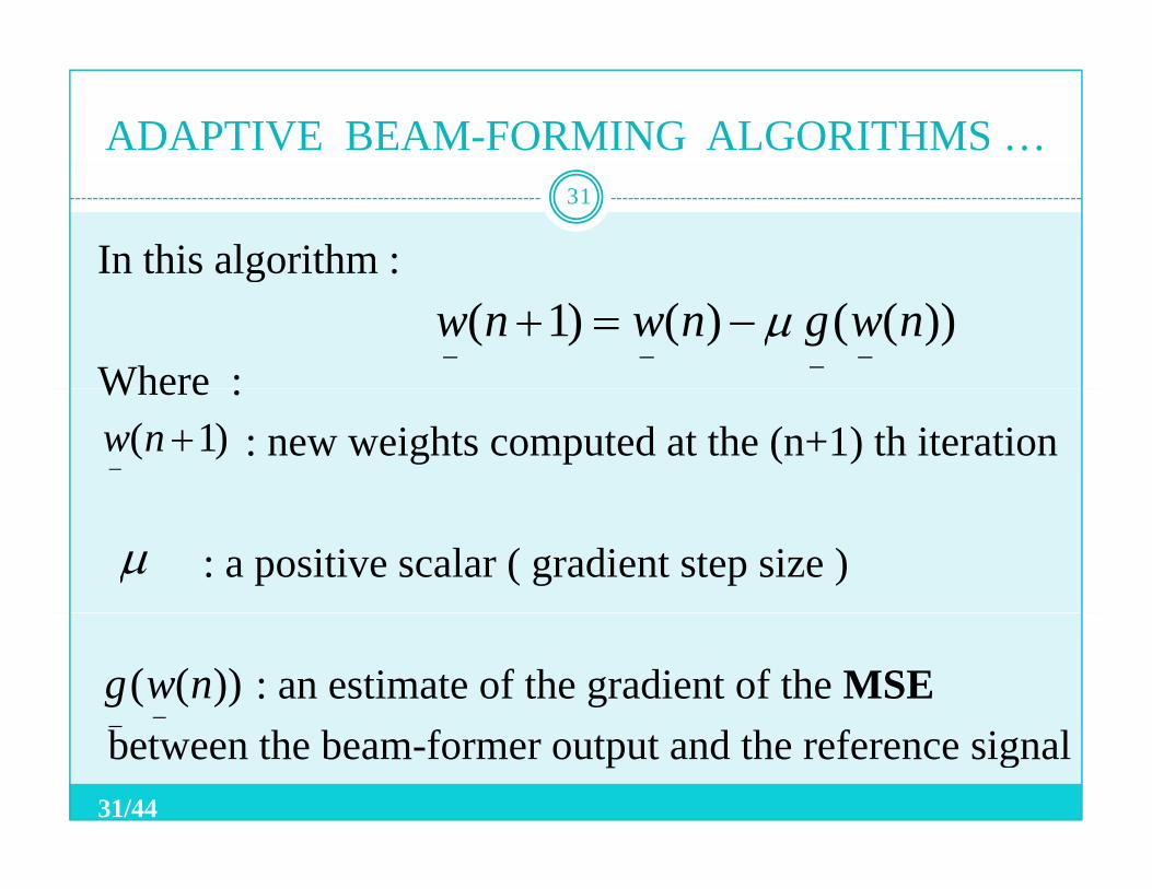
In this algorithm :
31
g
Where :))(()()1( nwgnwnw
−−−−−=+ µ
Where :: new weights computed at the (n+1) th iteration)1( +
−nw
: a positive scalar ( gradient step size ) µ
: an estimate of the gradient of the MSE))(( nwg−
between the beam-former output and the reference signal −
31/44
ADAPTIVE BEAM-FORMING ALGORITHMS …32
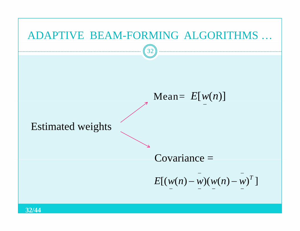
Mean= )]([ nwE
Estimated weights
)]([−
g
Covariance =Covariance
]))()()([( TwnwwnwE−−
−−−−−−
32/44
ADAPTIVE BEAM-FORMING ALGORITHMS …
The algorithm updates the weights at each iteration by
33
g p g yestimating the gradient of the MSE surface and thenmoving the weights in the negative direction of themoving the weights in the negative direction of the gradient by a small amount .)(µ
• should be small enough for convergence of the l ith t th ti i htµ
algorithm to the optimum weights .(convergence : convergence the mean of the estimated weights to the optimal weights )
33/44
ADAPTIVE BEAM-FORMING ALGORITHMS …
Convergence speed :
34
g pThe speed by which the mean of the estimated weights (ensemble average of many trials) approachesweights (ensemble average of many trials) approachesthe optimal weights .
• The larger the eigenvalue spread of the correlation t i R th l it t k f th l ith tmatrix R, the longer it takes for the algorithm to
converge.
34/44
ADAPTIVE BEAM-FORMING ALGORITHMS …
The availability of time for an algorithm to converge 35
y g gfor mobile communications depends on:
1-System design the duration that the user signal ispresent (e.g. User slot duration in a TDMA system)
2-The rate of the fading :The higher the rate at which the signal fades algorithm needs to converge faster
35/44
ADAPTIVE BEAM-FORMING ALGORITHMS …
Even when the mean of the estimated weights
36
gconverges to the optimal weights, they have finitecovariancecovariance .
The average MSE is more than MMSE
Misadjustment = ( average excess MSE ) /MMSE
Misadjustment the size of the region that i ht d i d it ft thweights wandering around it after the convergence.
36/44
ADAPTIVE BEAM-FORMING ALGORITHMS …
Increasing increases the misadjustment .µ37
g j
An increase in causes the algorithm to converge
µ
µAn increase in causes the algorithm to convergefaster.
µ
W h t d ff iWe have a trade off inthe selection of the gradient step sizeµ
37/44
ADAPTIVE BEAM-FORMING ALGORITHMS …
This trade off is between :
38
1-Reaching vicinity of the solution point more quickly1 Reaching vicinity of the solution point more quickly but wandering around over a larger region and causing a bigger misadjustmenta bigger misadjustment .
2 A i i th l ti i t l l ith th2-Arriving near the solution point slowly with thesmaller movement in the weights at the end.
38/44
ADAPTIVE BEAM-FORMING ALGORITHMS …
We select based on the following considerations :µ39
g
• The mentioned trade off
µ
The mentioned trade off • Being small enough for convergence • Application and requirements• Application and requirements
39/44
CONTENT
Introduction
40
Smart antenna and SDRSeveral beam-forming methodsSeveral beam forming methodsEssential signal-processing algorithmsAdaptive beam-forming algorithmsAdaptive beam forming algorithmssummery
40/44
SUMMARY
Smart antenna
41
• Beam-forming• Diversity combining• …
Smart antenna and SDR
Different beam-formerse e be o e s• Delay and sum beam-former
41/44
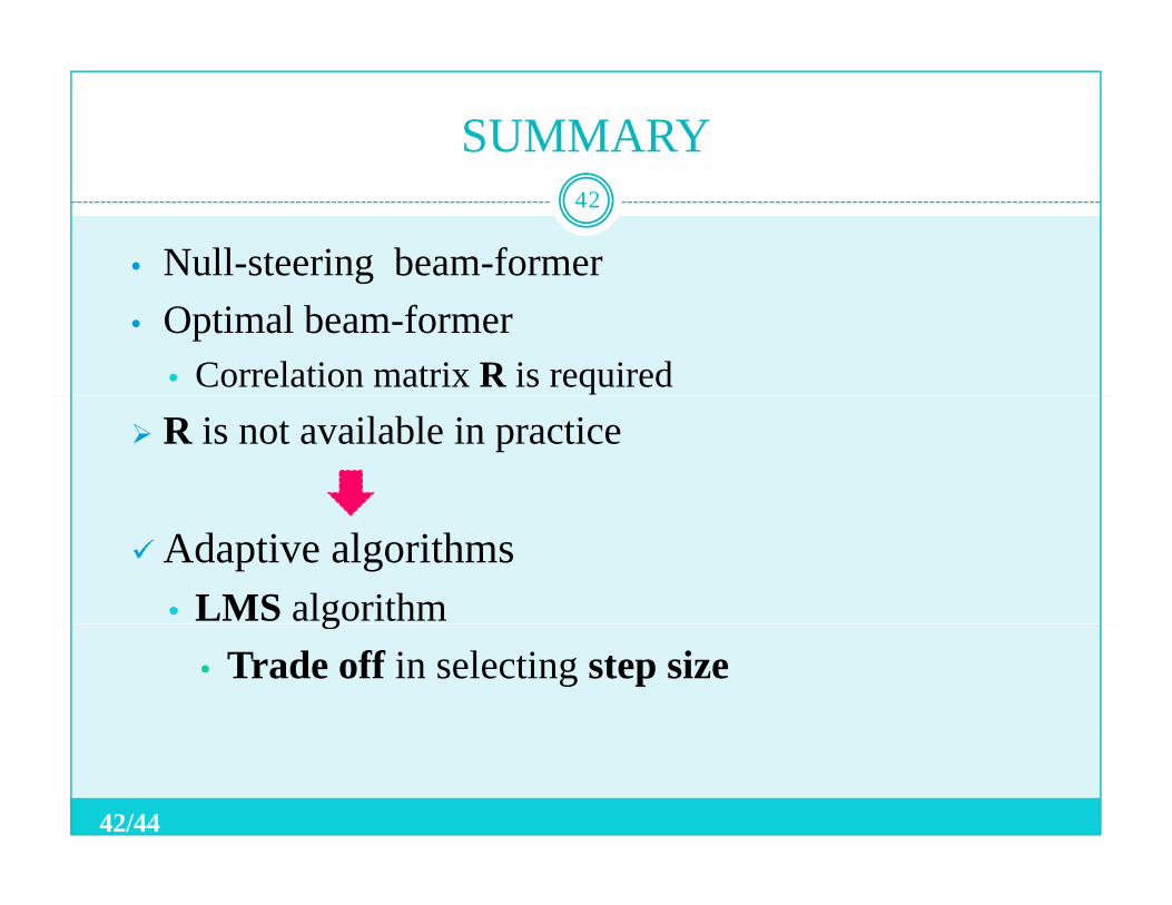
SUMMARY
• Null-steering beam-former
42
g• Optimal beam-former
• Correlation matrix R is requiredR is not available in practice
Adaptive algorithms• LMS algorithmg
• Trade off in selecting step size
42/44

QUESTIONS ?QUESTIONS ?
43/44

THANKS FOR YOUR ATTENTION
44/44


![[en] Itto Ts33](https://img.pdfslide.us/doc/110x75/577d23861a28ab4e1e9a0893/en-itto-ts33.jpg)