Embed Size (px)
Citation preview
Presentation forMACHINE TOOLS AND METROLOGYDEPARTMENT OF MECHANICAL ENGINEERING
B.TECH : V SEM
Dr. K CH APPARAOAssociate Professor
by
2
UNIT - I
BASIC MECHANISM OF METAL CUTTING
Manufacturing: The making of articles on a large scale usingMachinery. Converting raw material, components or parts in tofinished goods that meets a customer expectations.
- Machine and Machine Tool
- Machine: which will do only a particular work. It can’t make itsown parts
- example: Washing Machine
- Machine Tool: it is also a machine but it can produce its ownparts.
3
Definition of Manufacturing & Machine Tools
Existence of some form of crude machine tool is recorded asearly as 700 B.C. However, the most prominent beginning ofthe machine tool the John Wilkinson’s horizontal boringmachine towards 1775.
Henry Maudslay engine lathe 1794
Roberts Planer 1817
Maudslay combined a lead screw, a cross slide and changegears in a form, which is almost similar to the current daycentre lathe.
Eli Whitney Milling Machine 1818
4
Background of Machine Tools
John Nasmyth drilling machine 1840
Stefen Fitch first Turret Lathe 1845
Christoper Spencer automatic turret Lathe 1869
NC lathe 1952
5
NATURE OF RELATIVE MOTION BETWEEN THE TOOL AND WORKPIECE
1. FUNDAMENTALS OF METAL CUTTING2. FACTORS INFLUENCING CUTTING PROCESS 3. MECHANICS OF CHIP FORMATIO4. TYPES OF CHIPS5. CHIP BREAKERS6. CUTTING TOOL 7. TYPES OF CUTTING8. TEMPERATURE DISTRIBUTION 9. TOOL WEAR
ORGANIZATION

MACHIING CONDITIONS
M/C TOOL PRODUCT
WORKMATERAIL
CUTTINGTOOL
Metal Cutting Plastic Deformation/Flow Process
Orthogonal Cutting
Oblique Cutting
Classification of Cutting
INEFFICIENT BUT MOST IMPORTANT MANUFACTURING PROCESS
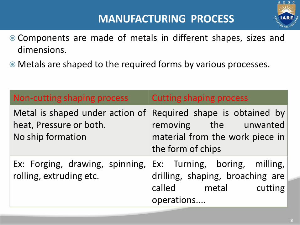
Components are made of metals in different shapes, sizes anddimensions.
Metals are shaped to the required forms by various processes.
8
MANUFACTURING PROCESS
Non-cutting shaping process Cutting shaping process
Metal is shaped under action ofheat, Pressure or both.No ship formation
Required shape is obtained byremoving the unwantedmaterial from the work piece inthe form of chips
Ex: Forging, drawing, spinning,rolling, extruding etc.
Ex: Turning, boring, milling,drilling, shaping, broaching arecalled metal cuttingoperations....
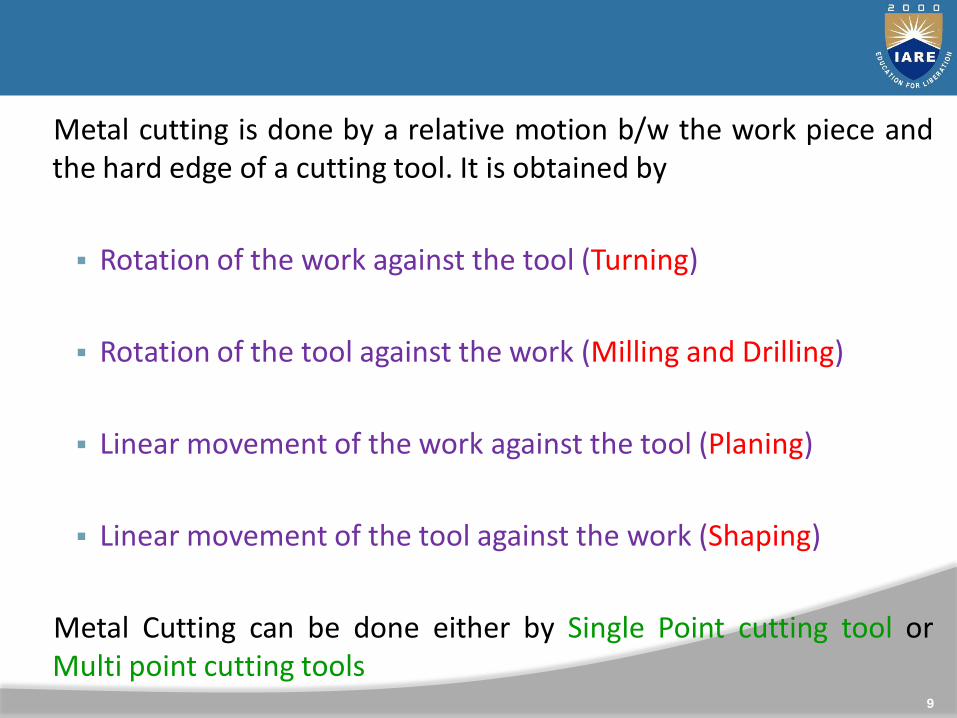
Metal cutting is done by a relative motion b/w the work piece andthe hard edge of a cutting tool. It is obtained by
Rotation of the work against the tool (Turning)
Rotation of the tool against the work (Milling and Drilling)
Linear movement of the work against the tool (Planing)
Linear movement of the tool against the work (Shaping)
Metal Cutting can be done either by Single Point cutting tool orMulti point cutting tools
9

Basic elements of cutting process:
Work piece, Tool, Chip
10
Elements of Metal Cutting
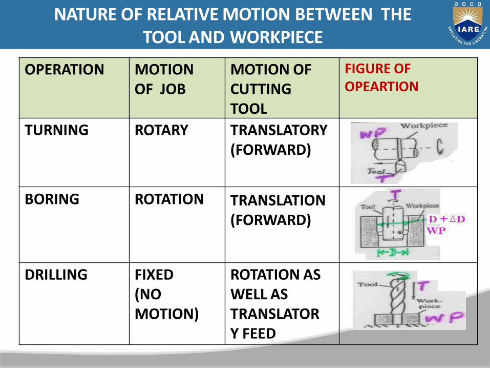
OPERATION MOTION OF JOB
MOTION OF CUTTING TOOL
FIGURE OF OPEARTION
TURNING ROTARY TRANSLATORY(FORWARD)
BORING ROTATION TRANSLATION(FORWARD)
DRILLING FIXED (NO MOTION)
ROTATION AS WELL AS TRANSLATOR Y FEED
NATURE OF RELATIVE MOTION BETWEEN THE TOOL AND WORKPIECE
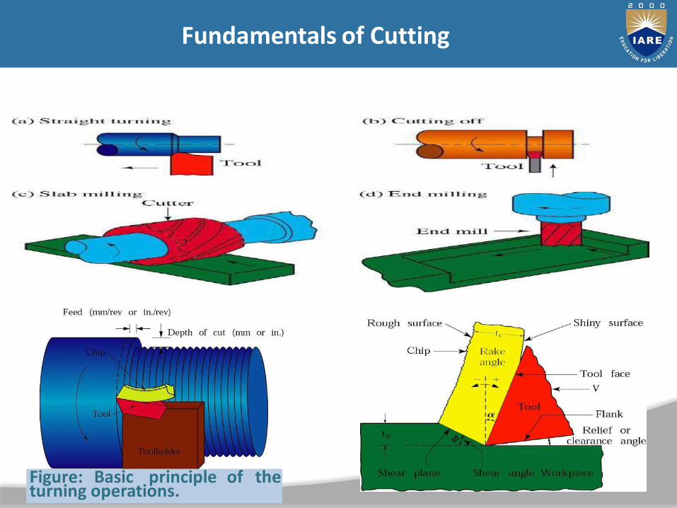
Figure: Basic principle of the turning operations.
Fundamentals of Cutting
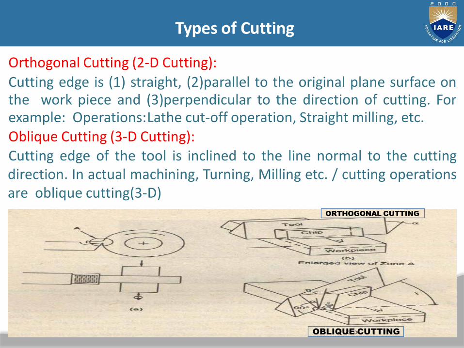
Orthogonal Cutting (2-D Cutting):
Cutting edge is (1) straight, (2)parallel to the original plane surface onthe work piece and (3)perpendicular to the direction of cutting. Forexample: Operations:Lathe cut-off operation, Straight milling, etc.Oblique Cutting (3-D Cutting):Cutting edge of the tool is inclined to the line normal to the cuttingdirection. In actual machining, Turning, Milling etc. / cutting operationsare oblique cutting(3-D)
ORTHOGONAL CUTTING
OBLIQUE CUTTING
Types of Cutting

14
When the tool advances in to the work piece, metal in front ofthe tool is severely stressed.
This cutting tool produces internal shearing action in the metal,so metal yields and flows plastically in the form of chips.
Compression of the metal under the tool takes place. When theultimate stress of the metal is exceeded, separation of metaltakes place in a localized area called shear plane and the chipmoves upward on the face of the tool.
This process is continued and a continuous chip formation takesplace.
15
Chip Formation Mechanism

The grains of the metal in front of the Tool cutting edge startelongating along line AB.
This elongation continues until the grains are completelydeformed along the line CD.
The region b/w the lines AB and CD is called shear zone.
After passing the shear zone, the deformed metal slides along thetool face due to the velocity of cutting tool.
16

(a) Basic mechanism of chip formation in metal cutting.
(b) Velocity diagram in the cutting zone.
V= Cutting velocity, Vs= Shear velocity, Vc=Chip velocity
Φ= Shear angle, α=Rake angle
Mechanics of Chip Formation
18

Types of Chips
Continues ChipsDiscontinues ChipsContinuous Chips
with Built up Edge (BUE)
Conditions for Continuous Chips:• Sharp cutting edges• Low feed rate (f)• Large rake angle (α)
• Ductile work material• High cutting speed (v=)• Low friction at Chip-Tool interface
Fig; Schematic ofchip formation
Fig; Schematic of different types ofchip
CHIP FORMATION
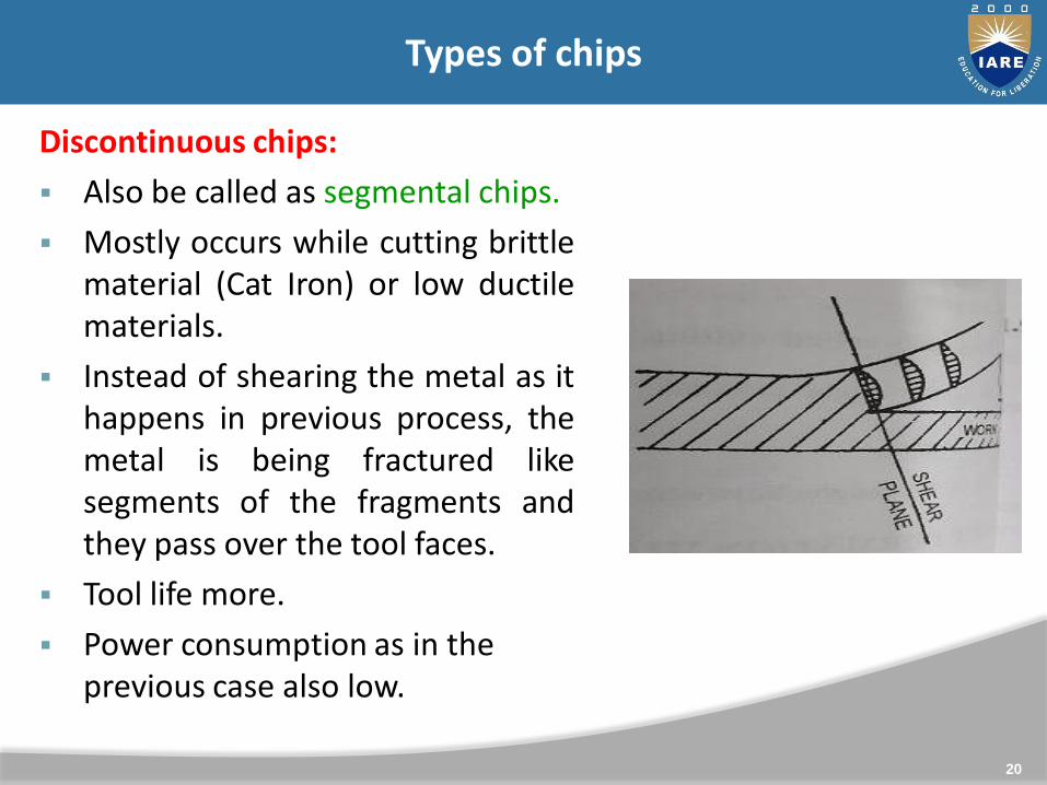
Discontinuous chips:
Also be called as segmental chips.
Mostly occurs while cutting brittlematerial (Cat Iron) or low ductilematerials.
Instead of shearing the metal as ithappens in previous process, themetal is being fractured likesegments of the fragments andthey pass over the tool faces.
Tool life more.
Power consumption as in the previous case also low.
20
Types of chips

Continuous Chips:
When cutting a ductile material, the compression of the metal is followed by the high heat at tool face.
This in turns enables the partof the removed metal to bewelded into the tool. Thisproduces rough surface finishand the tool life may bereduced.
21
Types of chips

22
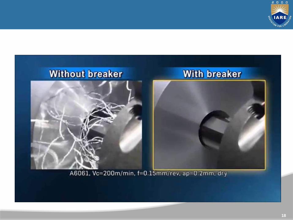
In operation at high cutting speeds, when a large quantity ofinconvenient and hazardous steel chips Is produced in a shorttime, the problem of curling or breaking the chips into smallpieces becomes one of primary importance
Types of chips
Chip Breakers
Long continuous chips are undesirable Chip breaker is a piece of metal clamped to the rake surface
of the tool which bends the chip and breaks it Chip can also be broken by changing the tool geometry,
thereby controlling the chip flow

23
Chip Breakers
24
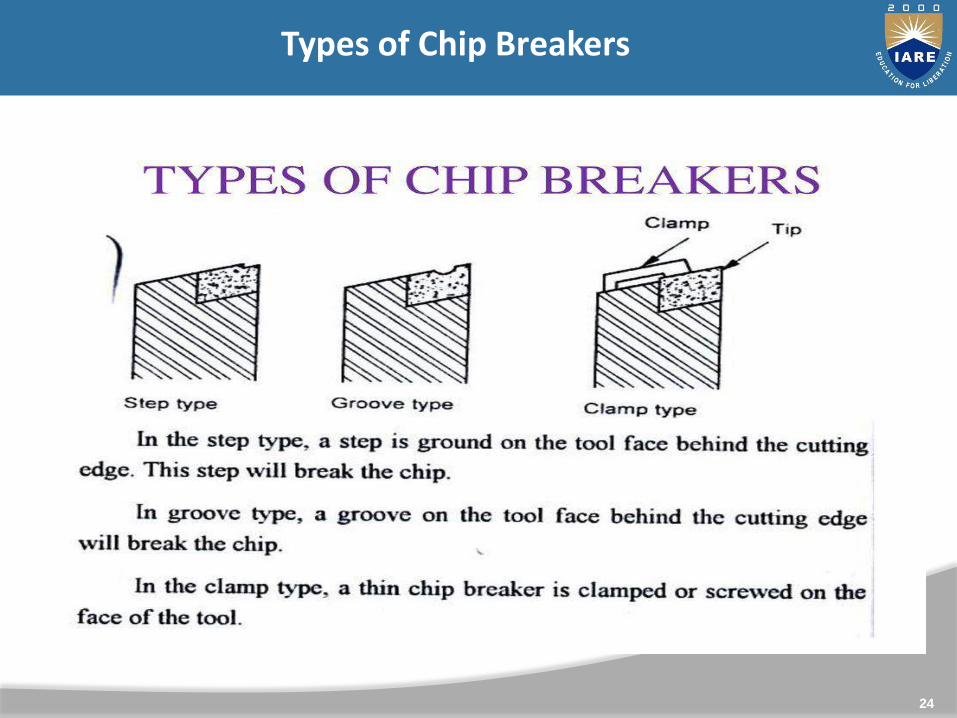
Types of Chip Breakers

• The chip breaker break the produced chips into small pieces.
• The work hardening of the chip makes the work of the chip
breakers easy. When a strict chip control is desired, some sort of
chip breaker has to be employed. The following types of chip
breakers are commonly used:
• Groove type
• Step type
• Secondary Rake type
• Clamp type
Fig: Schematics of different types of chip barkers
Chip- Breaking

(1) Single Point Cutting Tool
(2) Multi point Cutting Tool
Single Point Cutting Tool: It has effective cutting edge and removesexcess material along cutting edge
Types: (a) Ground Type, (b) Forged Type
(c) Tipped Type, (d) Bit Type
(a) Ground Type: Cutting edge is formed by grinding the endof a piece of tool steel stock
(b) Forged Type: Cutting edge is formed by rough forgingbefore hardening and grinding
26
Classification of cutting tools
(c) Tipped Type: Cutting edge is in the form of a small tip made ofhigh grade material which is welded to shankmade up of low grade material.
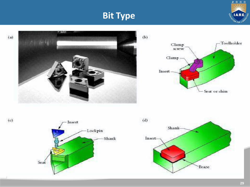
(d) Bit Type: A high grade material of square, rectangular or someother shape is held mechanically in a tool holder.
Single point cutting tools are commonly used in Lathe, shapers,planers, boring M/C and Slotters.
27
Classification of cutting tools
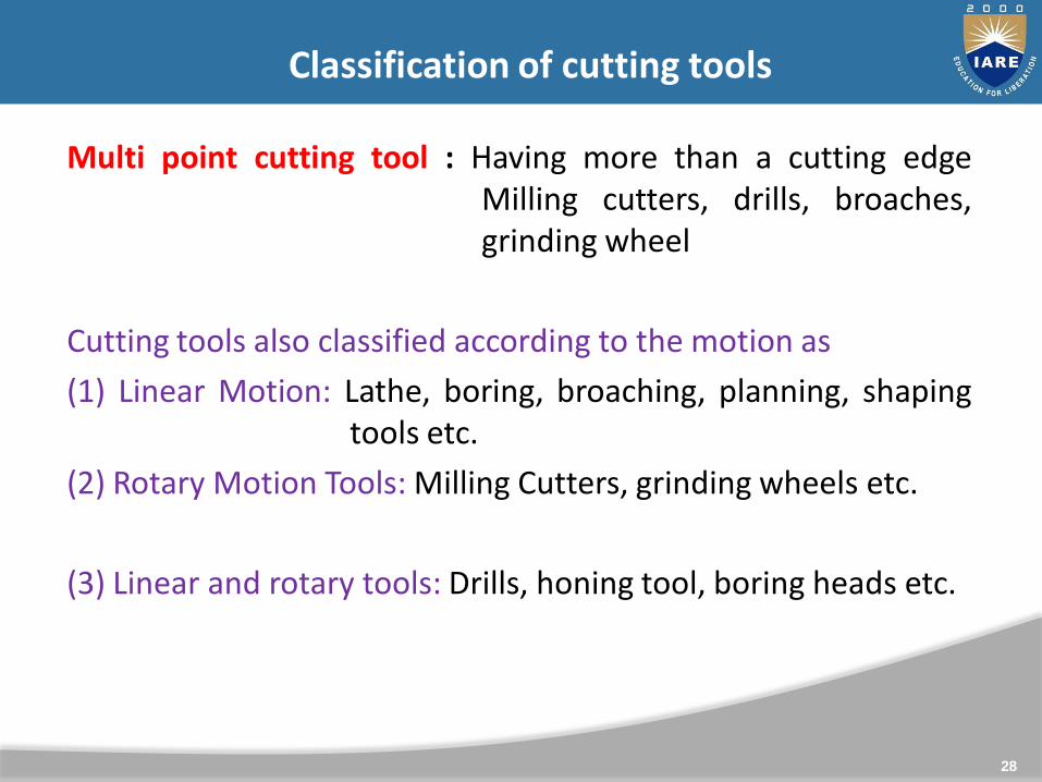
Multi point cutting tool : Having more than a cutting edgeMilling cutters, drills, broaches,grinding wheel
Cutting tools also classified according to the motion as
(1) Linear Motion: Lathe, boring, broaching, planning, shapingtools etc.
(2) Rotary Motion Tools: Milling Cutters, grinding wheels etc.
(3) Linear and rotary tools: Drills, honing tool, boring heads etc.
28
Classification of cutting tools
29
Bit Type
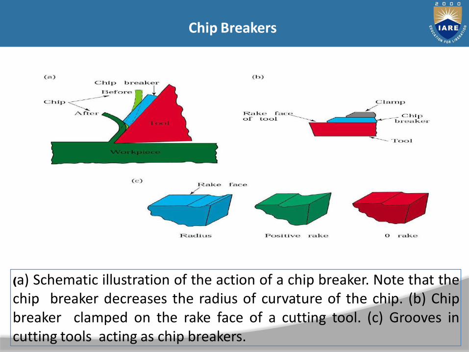
(a) Schematic illustration of the action of a chip breaker. Note that thechip breaker decreases the radius of curvature of the chip. (b) Chipbreaker clamped on the rake face of a cutting tool. (c) Grooves incutting tools acting as chip breakers.
Chip Breakers
31

32
33
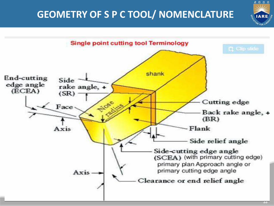
GEOMETRY OF S P C TOOL/ NOMENCLATURE
(a)
(c)
(b)
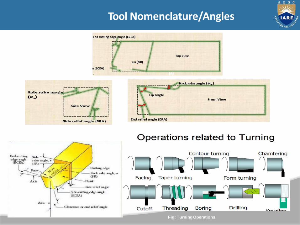
Fig: TurningOperations
Tool Nomenclature/Angles
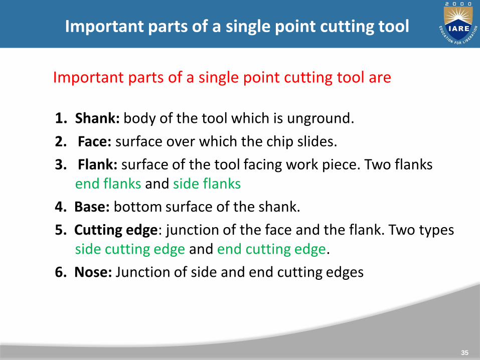
1. Shank: body of the tool which is unground.
2. Face: surface over which the chip slides.
3. Flank: surface of the tool facing work piece. Two flanks end flanks and side flanks
4. Base: bottom surface of the shank.
5. Cutting edge: junction of the face and the flank. Two types side cutting edge and end cutting edge.
6. Nose: Junction of side and end cutting edges
35
Important parts of a single point cutting tool are
Important parts of a single point cutting tool

(a)
Fig: Terms used in metal cutting (a) Positive rake; (b)Negative rake
Tool Nomenclature/Angles
(b)
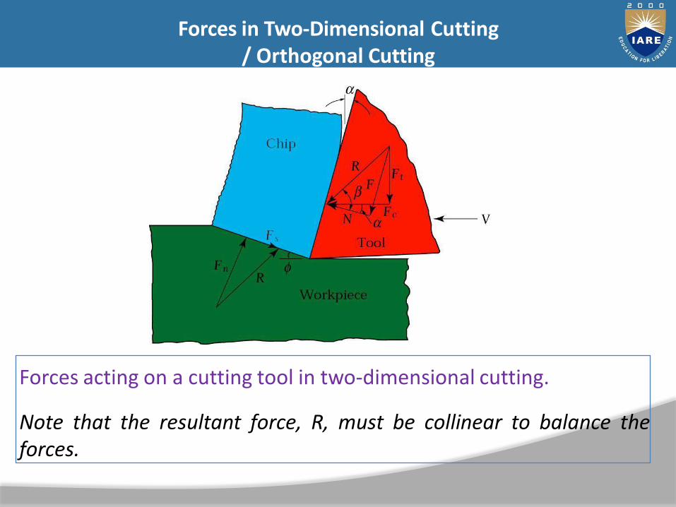
Forces acting on a cutting tool in two-dimensional cutting.
Note that the resultant force, R, must be collinear to balance theforces.
Forces in Two-Dimensional Cutting/ Orthogonal Cutting
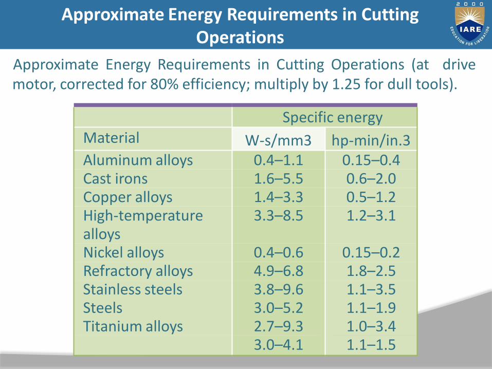
Approximate Energy Requirements in Cutting Operations (at drivemotor, corrected for 80% efficiency; multiply by 1.25 for dull tools).
Specific energyMaterial W-s/mm3 hp-min/in.3Aluminum alloys 0.4–1.1 0.15–0.4Cast irons 1.6–5.5 0.6–2.0Copper alloys 1.4–3.3 0.5–1.2High-temperature alloys
3.3–8.5 1.2–3.1
Nickel alloys 0.4–0.6 0.15–0.2Refractory alloys 4.9–6.8 1.8–2.5Stainless steels 3.8–9.6 1.1–3.5Steels 3.0–5.2 1.1–1.9Titanium alloys 2.7–9.3 1.0–3.4
3.0–4.1 1.1–1.5
Approximate Energy Requirements in CuttingOperations
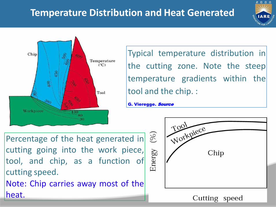
Typical temperature distribution in
the cutting zone. Note the steep
temperature gradients within the
tool and the chip. :
G. Vieregge. Source
Percentage of the heat generated incutting going into the work piece,tool, and chip, as a function ofcutting speed.Note: Chip carries away most of theheat.
Temperature Distribution and Heat Generated
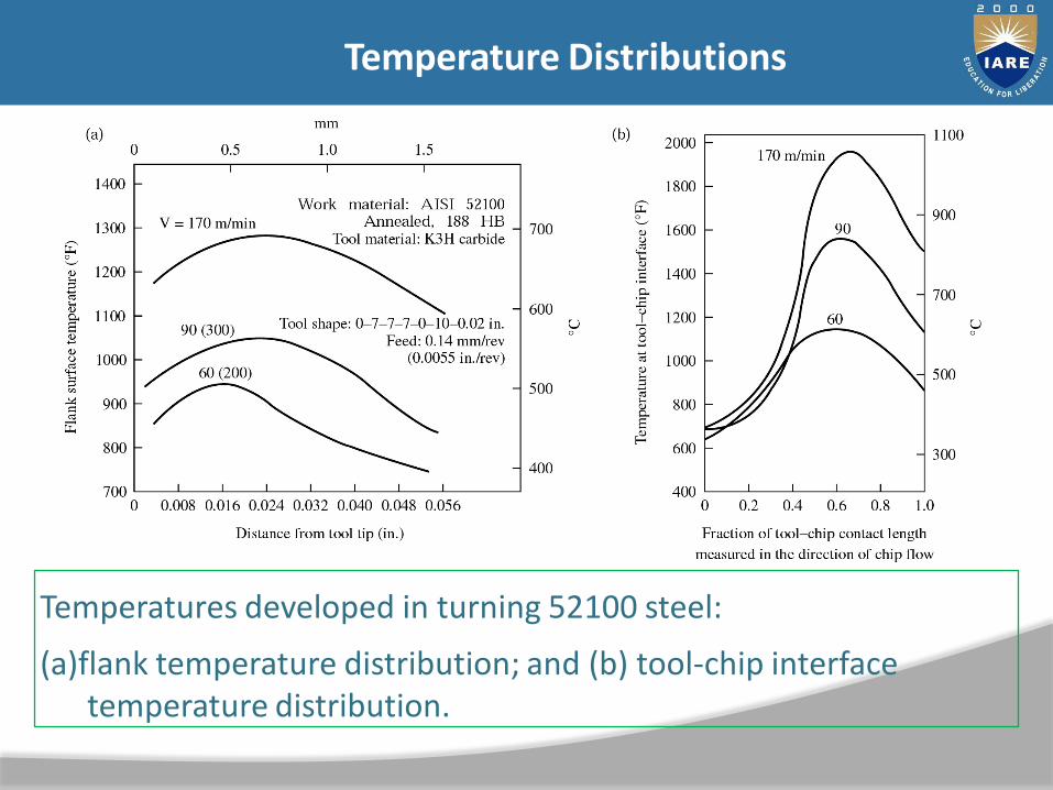
Temperatures developed in turning 52100 steel:
(a)flank temperature distribution; and (b) tool-chip interface temperature distribution.
Temperature Distributions
(e)(d)
(a)(b)
(c)
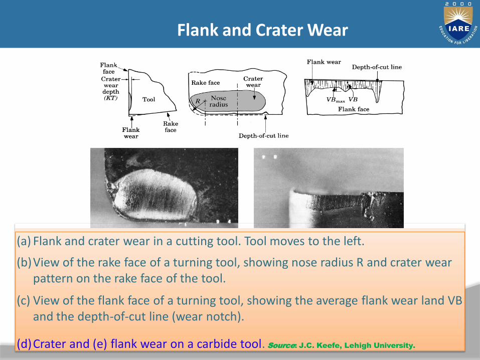
(a) Flank and crater wear in a cutting tool. Tool moves to the left.
(b)View of the rake face of a turning tool, showing nose radius R and crater wear pattern on the rake face of the tool.
(c) View of the flank face of a turning tool, showing the average flank wear land VB and the depth-of-cut line (wear notch).
(d)Crater and (e) flank wear on a carbide tool. Source: J.C. Keefe, Lehigh University.
Flank and Crater Wear
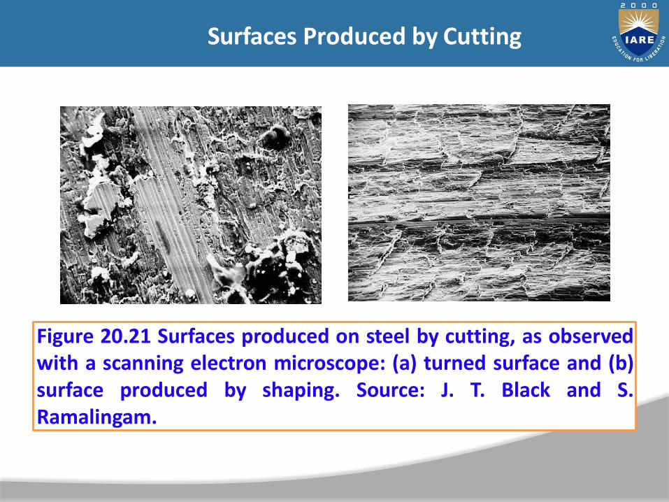
Figure 20.21 Surfaces produced on steel by cutting, as observedwith a scanning electron microscope: (a) turned surface and (b)surface produced by shaping. Source: J. T. Black and S.Ramalingam.
(b)(a)
Surfaces Produced by Cutting
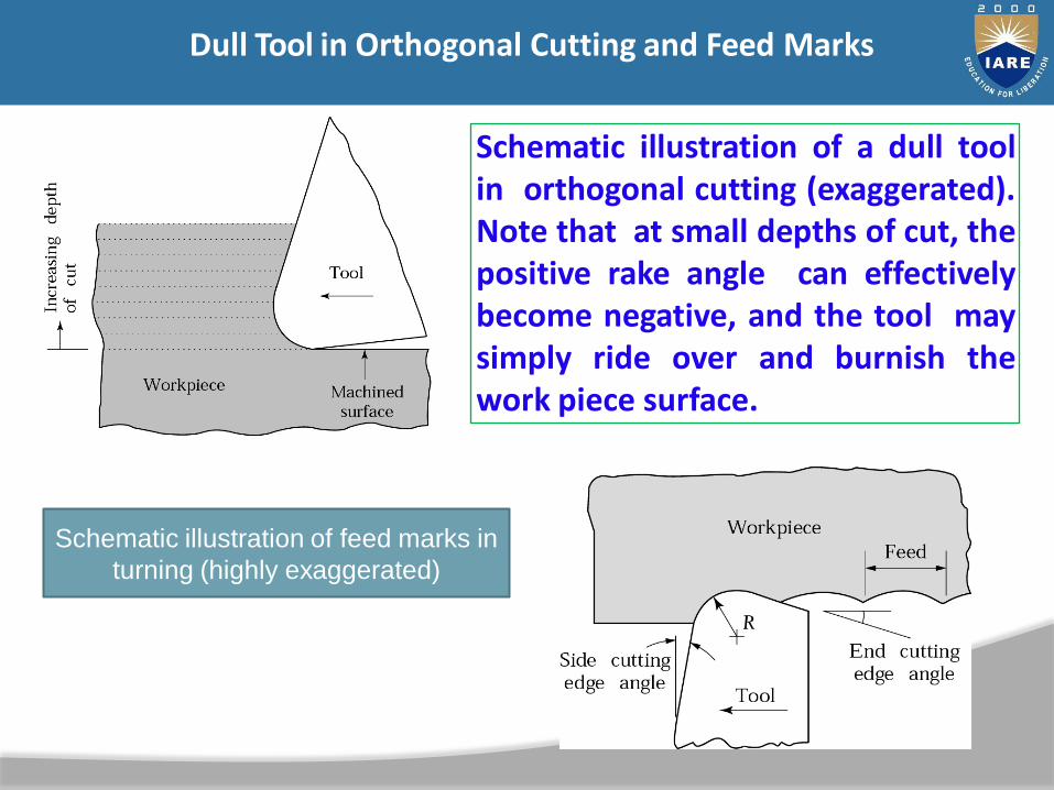
Schematic illustration of a dull toolin orthogonal cutting (exaggerated).Note that at small depths of cut, thepositive rake angle can effectivelybecome negative, and the tool maysimply ride over and burnish thework piece surface.
Dull Tool in Orthogonal Cutting and Feed Marks
Schematic illustration of feed marks in
turning (highly exaggerated)
44
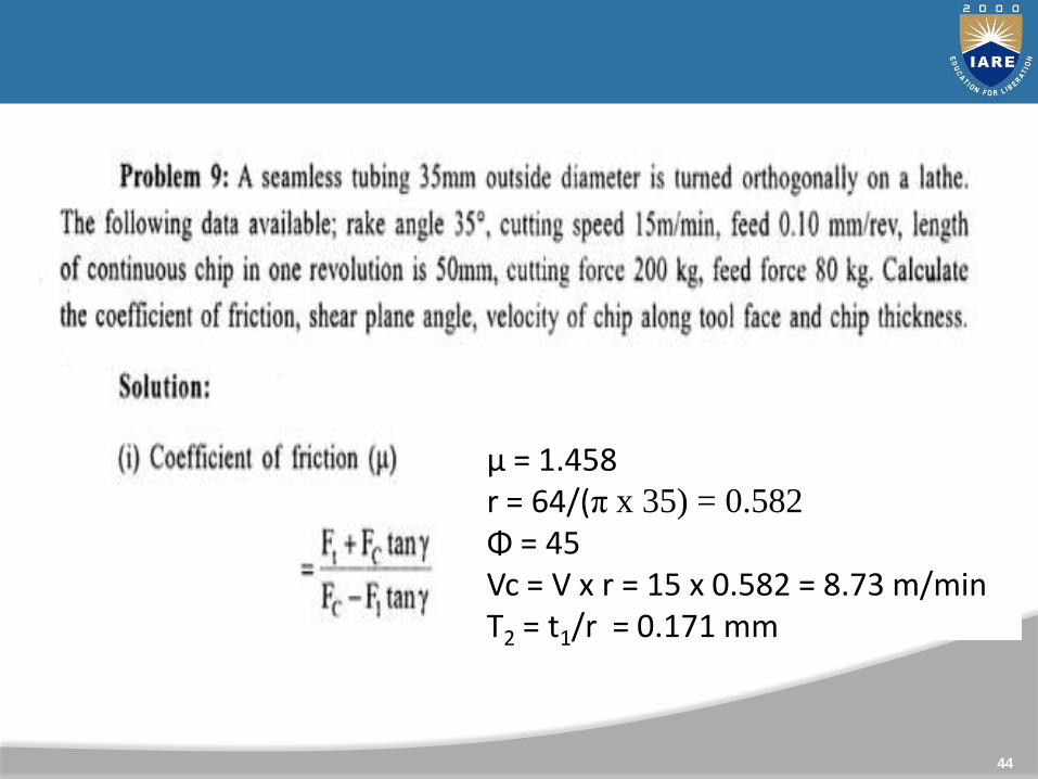
µ = 1.458r = 64/(π x 35) = 0.582
Φ = 45Vc = V x r = 15 x 0.582 = 8.73 m/minT2 = t1/r = 0.171 mm

45
Tool Life
Tool Life: It represents the use full life of the toolTime from the start of cut to some end point defined by failurecriterion
Factors influencing the tool life
1. Cutting Speed2. Feed and Depth of Cut3. Tool geometry4. Tool Material5. Cutting Fluid6. Work Materials7. Rigidity of work, tool and machine

46
1. Cutting Speed• It has the greater influence on the tool life.• When cutting speed increase , cutting Temperature
increases.• Hardness of the tool deceases• Hence, tool flank wear and crater wear occurs easily.• Due to these reasons tool life decreases.• The relation b/w the tool life and cutting speed is
expressed by Taylor’s formulaVTn = C
T : Tool lifeN : exponent (depends on tool and work)for HSS and MS …… n = 0.1
Factors influencing the tool life
47
2. Feed and Depth of cut• Tool life is depends up on the amount of material removed
by the tool per minute.• For a given cutting speed, if the feed or depth of cut is
increased, the rate of metal removal will reduce the tool life.
3. Tool geometry• Large rake angle reduces the tool cross section, so area of
tool which will absorb heat is reduced.• If the cutting angle increases, more power will be required
cutting.• Clearance angle will improve tool life at first, then TL
decreases because of decreased strength. So correctclearance angle is 100 to 150.
Factors influencing the tool life
48
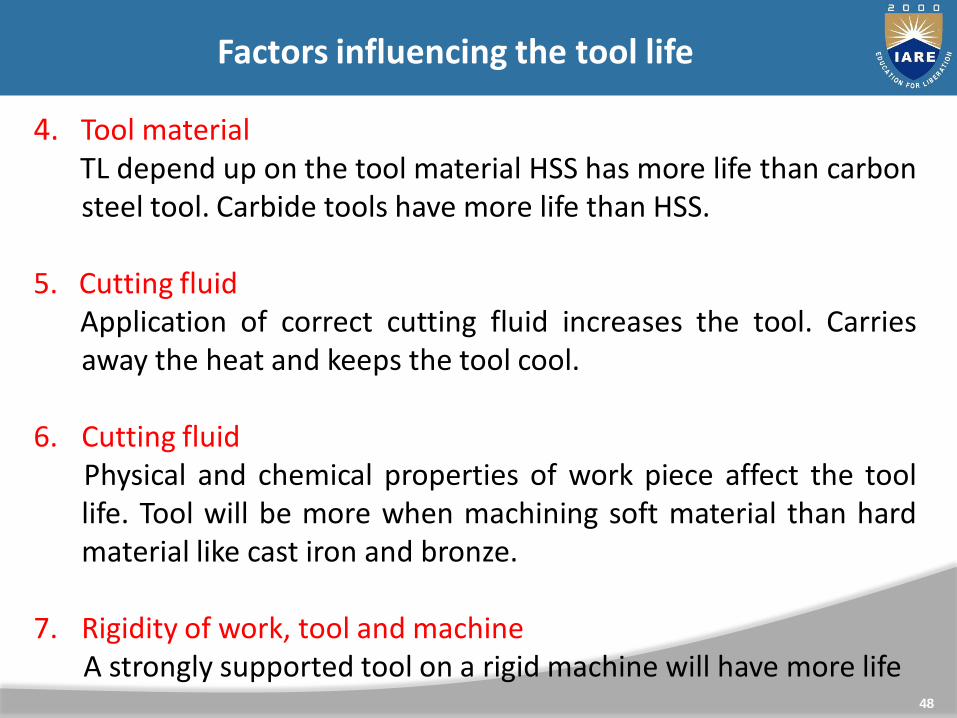
4. Tool materialTL depend up on the tool material HSS has more life than carbonsteel tool. Carbide tools have more life than HSS.
5. Cutting fluidApplication of correct cutting fluid increases the tool. Carriesaway the heat and keeps the tool cool.
6. Cutting fluidPhysical and chemical properties of work piece affect the toollife. Tool will be more when machining soft material than hardmaterial like cast iron and bronze.
7. Rigidity of work, tool and machineA strongly supported tool on a rigid machine will have more life
Factors influencing the tool life

49
Tool life equationsConstant C mainly depends upon the tool , work piece, feed,depth of cut, type of coolant and tool geometry etc.
Tool life equations (Taylor’s Equation)
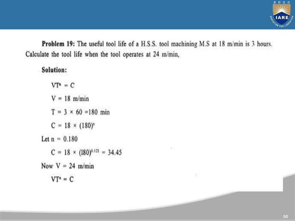
50
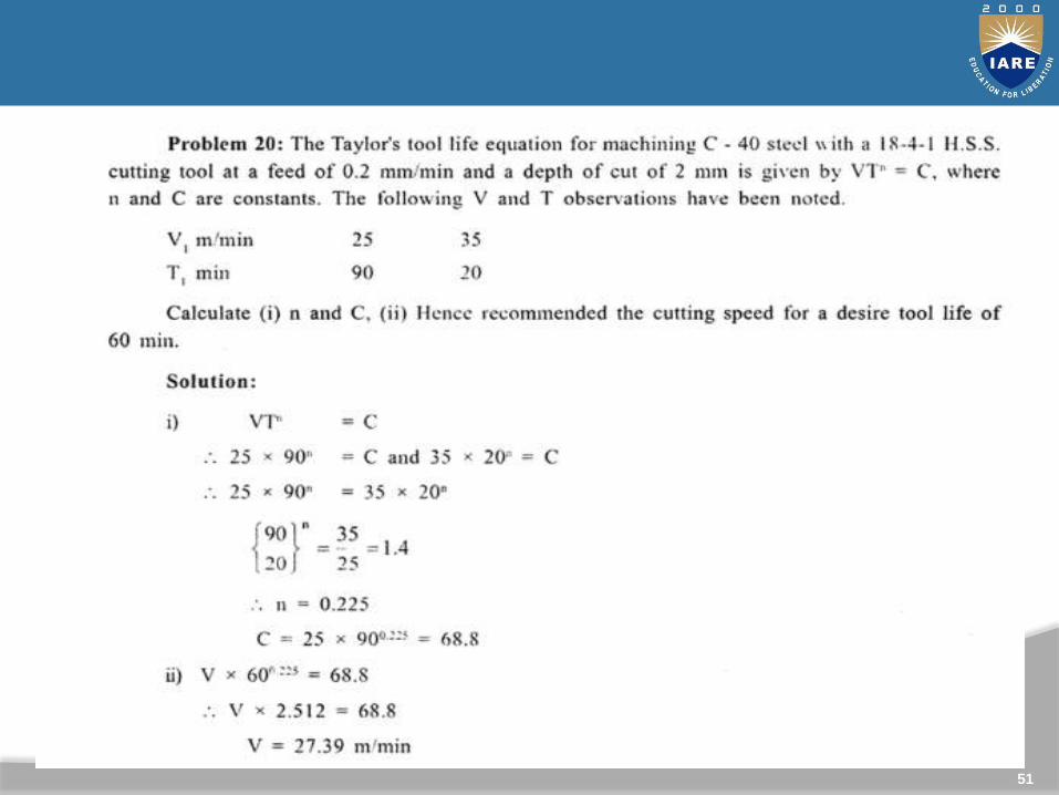
51
52
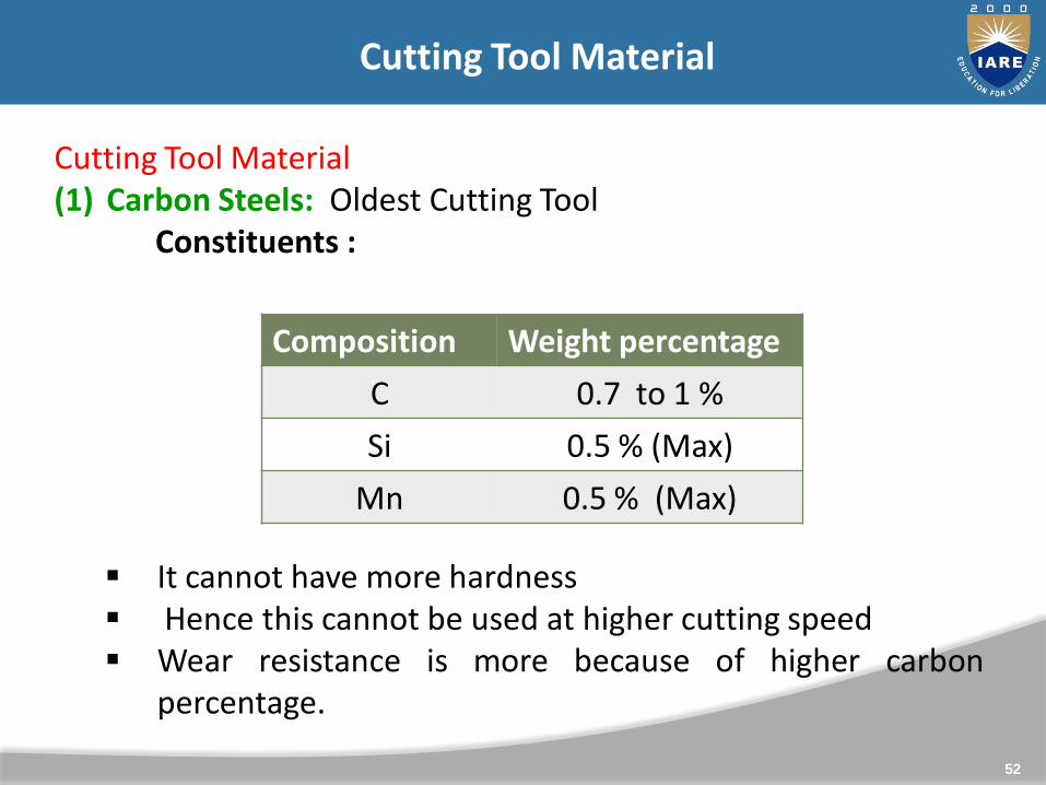
Cutting Tool Material(1) Carbon Steels: Oldest Cutting Tool
Constituents :
It cannot have more hardness Hence this cannot be used at higher cutting speed Wear resistance is more because of higher carbon
percentage.
Cutting Tool Material
Composition Weight percentage
C 0.7 to 1 %
Si 0.5 % (Max)
Mn 0.5 % (Max)
53
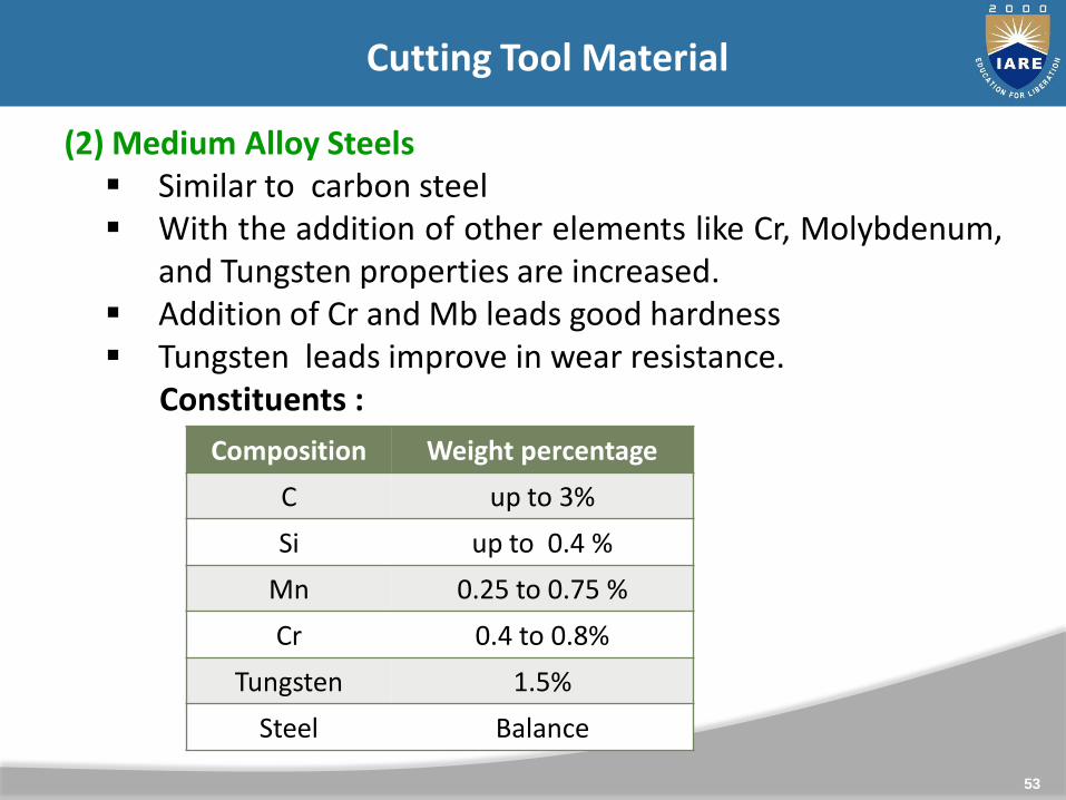
(2) Medium Alloy Steels Similar to carbon steel With the addition of other elements like Cr, Molybdenum,
and Tungsten properties are increased. Addition of Cr and Mb leads good hardness Tungsten leads improve in wear resistance.
Constituents :
Cutting Tool Material
Composition Weight percentage
C up to 3%
Si up to 0.4 %
Mn 0.25 to 0.75 %
Cr 0.4 to 0.8%
Tungsten 1.5%
Steel Balance
54
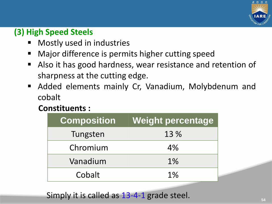
(3) High Speed Steels Mostly used in industries Major difference is permits higher cutting speed Also it has good hardness, wear resistance and retention of
sharpness at the cutting edge. Added elements mainly Cr, Vanadium, Molybdenum and
cobaltConstituents :
Simply it is called as 13-4-1 grade steel.
Composition Weight percentage
Tungsten 13 %
Chromium 4%
Vanadium 1%
Cobalt 1%
55
(4) Cemented Carbide tools Cemented carbide tool material is prepared by Powder
metallurgy process Final powder mixture consisting of varies elements is pressed
in order to get required shape And sintered in to cemented carbide.
(5) Ceramic tools Aluminium oxide is known as ceramic tool. Al2O3 powder is
prepared in a mould and pressed of about 300 kg/cm2 isapplied and then sintered.
The tool tip is prepared by this process and is fitted with thetool shank
Cutting Tool Material
56
It can operate at high cutting speed They have high compressive strength They are brittle in nature They have low bending strength.
(6) Abrasives• Abrasive grains such as Al2O3 and SiC . They are used in
grinding wheels• They are used to remove a very small portion of material in
the work piece for final operations
57
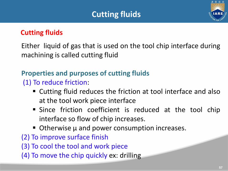
Cutting fluids
Either liquid of gas that is used on the tool chip interface duringmachining is called cutting fluid
Properties and purposes of cutting fluids(1) To reduce friction: Cutting fluid reduces the friction at tool interface and also
at the tool work piece interface Since friction coefficient is reduced at the tool chip
interface so flow of chip increases. Otherwise µ and power consumption increases.
(2) To improve surface finish(3) To cool the tool and work piece(4) To move the chip quickly ex: drilling
Cutting fluids
58
Important properties It should absorb more heat It should reduce friction Should not be corrosive in nature Should have low viscosity Should be economical
Important cutting fluids Carbon Tetrachloride Acetic acid Turpentine Kerosene Paraffin oil Soluble oil Water
Cutting fluids

59
UNIT - II
MACHINE TOOLS - I
60
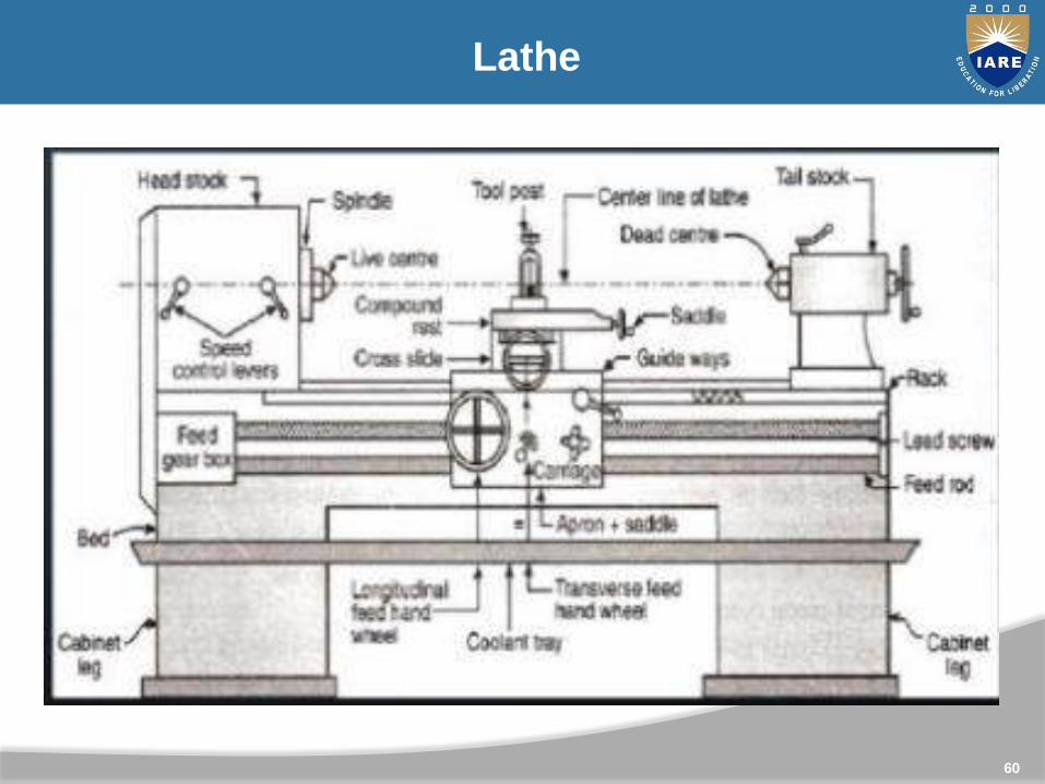
Lathe

5 - 61
Introduction
A lathe is one of the oldest & most important machine tools everdeveloped. The job to be machined is rotated & the cutting tool ismoved relative to the job. That is why, It’s also called as “ TurningMachine”.
A Lathe was basically developed to machine cylindrical surfaces.But many other operations can also be performed on lathes. e.g.-facing, parting, necking, knurling, taper turning & forming. We alsocan perform operations of other machine tools on a lathe, e.g.drilling, reaming, milling & drilling operation etc.
A lathe is called the mother of the entire machine tool family.
The lathe can be defined as a machine tool which holds the workbetween two rigid & strong centers, or in a chuck or face platewhile the latter revolves. The cutting tool is rigidly held &supported in a tool post & feed against the revolving work.

62
Lathe Bed
63
Lathe parts
Lathe Bed
Base of Machine
Made to support working parts of lathe
Head stock , carriage and tail stock are mounted on bed
carriage and tail stock are move over the bed
It has guide ways
it is very strong to resist the cutting forces and vibrations
Guide ways are very accurate for getting accuracy in jobs
Made of Cast iron with nickel chromium, alloying additions.
Heavy, rugged casting

64
Headstock

65
Head stock
Mounted on the bed at left side
It carries a hollow spindle
A large bar can pass through the hole of the spindle
The front end of the hole is tapered for holding tapered shanks
Chucks and face plates can be attached to the nose of the
spindle
It has driving and speed changing mechanism
Speed changing and feed changing levers are attached to the
head stock
66
Tail stock
Mounted on the right side of bed
Used for the supporting of right end of work
Also used for holding drilling, reamer or tap for drilling
operation
Can be moved and clamped at any position to support
different lengths of work
Tail stock body is bored and tail stock spindle moves through
is a dead centre can be fixed in to the taper hole of the
spindle for supporting

67
Tail stock
68
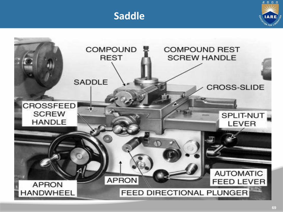
Saddle
H shaped casting fitted over the bed
Moves along the guide way
It carries the cross slide and tool post
It can be moved to the required position and locked to the bed.
Cross Slide
Attached to the saddle
Carries the compound rest and tool post
Can be moved by power or by hand
There is micrometer dial on the cross slide hand wheel with an
accuracy of 0.05mm.
69
Saddle
70
Compound rest
It marked in degrees
Used during taper turning to set tool for angular cut
No power feed only hand feed
The is micrometer dial for showing depth of cut
Should be locked strongly
Tool Post
Tool is clamped in the tool post
4 types of tool posts
(1) Single crew tool post
(2) Open side tool post
(3) Four bolt tool post
(4) Four way tool post.
71
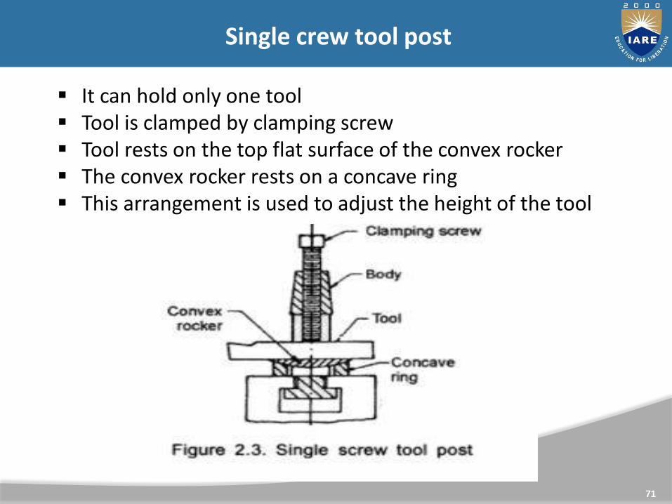
It can hold only one tool Tool is clamped by clamping screw Tool rests on the top flat surface of the convex rocker The convex rocker rests on a concave ring This arrangement is used to adjust the height of the tool
Single crew tool post

72
(2) Open side tool post
The tool is held in position by
two set screws
parallel packing strips are used
to adjust the height of the
cutting tool
The tool post can be tilted to
any required position by
loosening the clamp bolt.
The clamping bolt is fitted in a T
– slot ; so the tool can be
changed quickly.
73
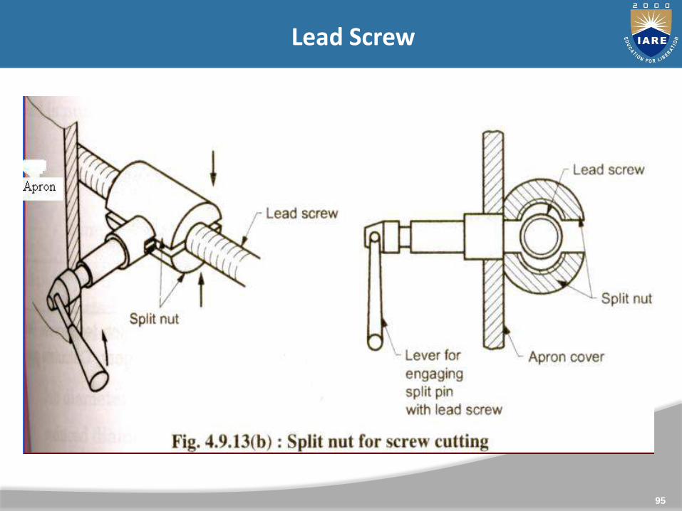
Apron
The apron is attached to the saddle and hangs in front of the bed
It has gears, levers and clutches for moving the carriage with the
lead screw for thread cutting.
The apron hand wheel is used to move the carriage parallel to
the lathe axis.
Feed Mechanism
The movement of the tool relative to the work piece termed as
“feed”
There are 3 types of feeds namely longitudinal, cross and angular.
If tool moves parallel to the axis of the lathe is called longitudinal
feed, it is achieved by moving carriage
When the tool moves perpendicular to the axis of the lathe that
is cross feed, it is achieved by moving cross slide
74
When the tool moves at an angle to the axis of the lathethat is called angular feed.
angular feed is achieved by moving compound slide, afterswiveling it at an angle to the lathe axis.
Feed Rod: It is a long shaft, used to move carriage or cross slide for
turning, facing, boring and all operations except threadcutting
Power is transmitted from the lathe spindle to the aprongears through the feed rod via large number of gears
75
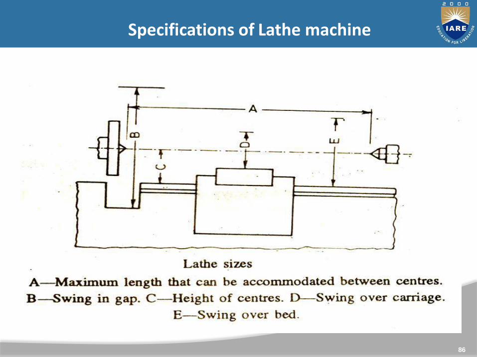
Specifications of Lathe
Size of lathe is specified as follows1. The length between the centers
maximum length of job that can be mounted between thecenters
2. The length of the bedthis gives approximate floor area that the lathe can occupy
3. Height of the centersit is measured from the lathe bed.
4. Maximum diameter over carriagethis is the diameter of the work or bar that may pass throughthe hole of the head stock spindle.
5. The swing diameter of the bedmaximum dia of the work that may revolve revolve over the bedways
6. The swing diameter over carriage : max dia of work that mayrotate over the saddle
76
Types of Lathe Machine
Speed Lathe
Engine Lathe
Bench Lathe
Tool Room Lathe
Capstan & Turret Lathe
Automatic Lathe
Special-Purpose Lathe.

77
Types of Lathe

78
Specifications of Lathe
1. Speed Lathe It consist of a bed, a head stock , a tail stock and an
adjustable tool post. As the speed of the spindle is very high, it is called as
speed lathe Spindle is driven by a high speed motor through belts Two or three range of spindle speeds are obtained by
step cone pulleys The work is mounted between centers or in a face
plate screwed in the main spindle Mainly it is used for wood turning or polishing a work
and for metal spinning.

79
Types of Lathe
1. Engine Lathe important and widely used type of lathe Early day, it was driven by steam engine so it is called as
engine lathe some times called as centre lathe It consists of a bed, a head stock, feed shaft and lead
screw mechanism and carriage Work is mounted on the head stock. Tool is mounted on
the carriage the tool may be fed cross wise or in longitudinal direction
by hand or automatically. More than six range of spindle speeds can be obtained by
change gears
80
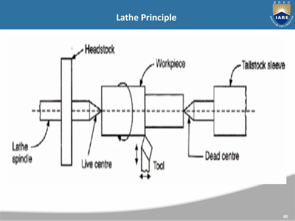
Lathe Principle
81

82
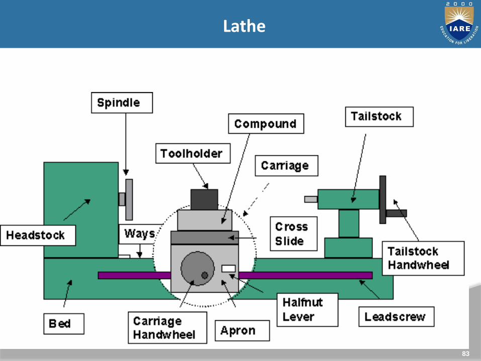
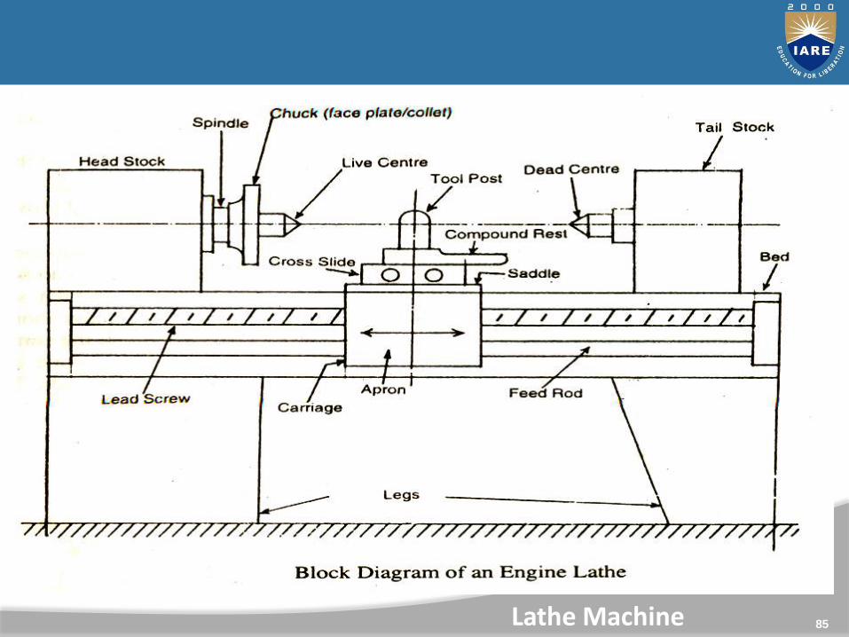
Block diagram of center lathe
83
Lathe
84
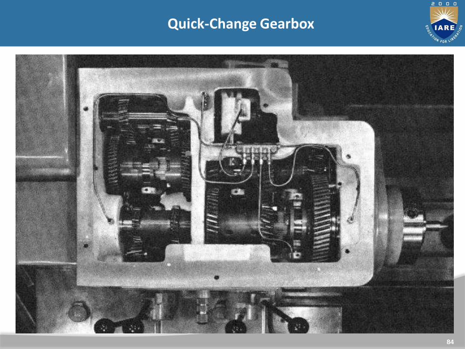
Quick-Change Gearbox
85Lathe Machine
86
Specifications of Lathe machine

87
Height of center
Length between the centers
Length of bed
The swing diameter over bed
The swing diameter over carriage
Maximum diameter of bar
Spindle speed, motor hp
Specification

88
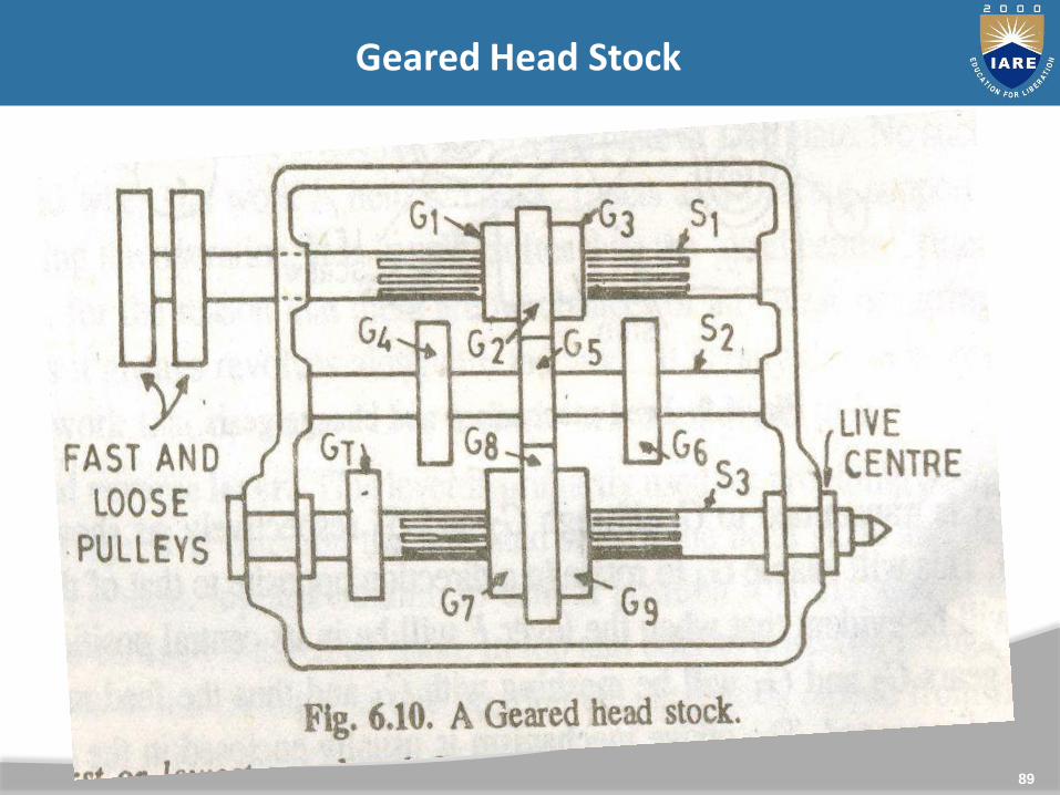
It is permanently fastened to the left hand end of the lathe. Itserves to support the first operative unit of the lathe, i.e.spindle. It’s also called as live centre because it turns with thework.
The headstock is that part of the lathe which serves as a housingfor the driving pulleys, back gears & spindle.
It consist of main parts:
1) Cone pulley,
2) Back gears & lever,
3) Main spindle,
4) Live centre, &
5) Feed reverse lever.
Headstock
89
Geared Head Stock

90
It’s on the other end of the bed from the headstock. It’s chieffunction is to hold the dead centre so that long work pieces canbe supported between centres.
Tailstock -
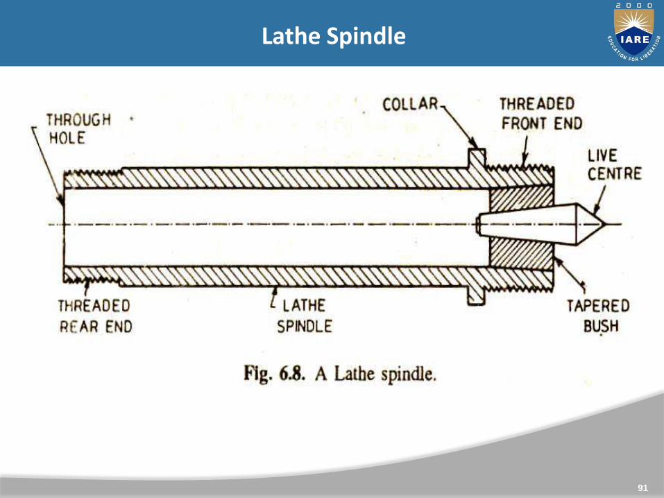
91
Lathe Spindle
92
In between the headstock & tailstock is the carriage. It’smovable on the bed ways and it’s purpose is to hold thecutting tool & to impart to it either longitudinal or crossfeed. It has five major parts:
a) Saddle
b) Cross slide
c) Compound rest
d) Tool post
e) Apron
Carriage
93
Lathe Carriage
94
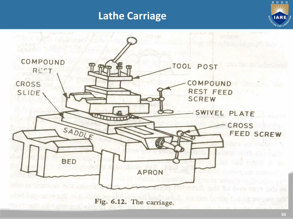
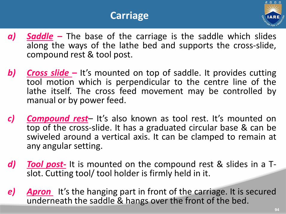
Carriage
a) Saddle – The base of the carriage is the saddle which slidesalong the ways of the lathe bed and supports the cross-slide,compound rest & tool post.
b) Cross slide – It’s mounted on top of saddle. It provides cuttingtool motion which is perpendicular to the centre line of thelathe itself. The cross feed movement may be controlled bymanual or by power feed.
c) Compound rest– It’s also known as tool rest. It’s mounted ontop of the cross-slide. It has a graduated circular base & can beswiveled around a vertical axis. It can be clamped to remain atany angular setting.
d) Tool post- It is mounted on the compound rest & slides in a T-slot. Cutting tool/ tool holder is firmly held in it.
e) Apron –It’s the hanging part in front of the carriage. It is securedunderneath the saddle & hangs over the front of the bed.
95
Lead Screw
96
Lathe Operations : Turning
A single point cutting tool removes material from a rotatingwork piece to generate a rotationally symmetric shape
Machine tool is called a lathe
Types of cuts: Facing Contour turning Chamfering Parting (Cut-off) / Grooving Threading
97
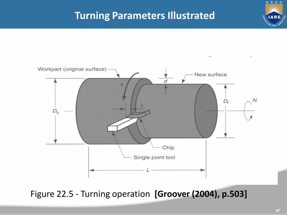
Turning Parameters Illustrated
Figure 22.5 - Turning operation [Groover (2004), p.503]
98
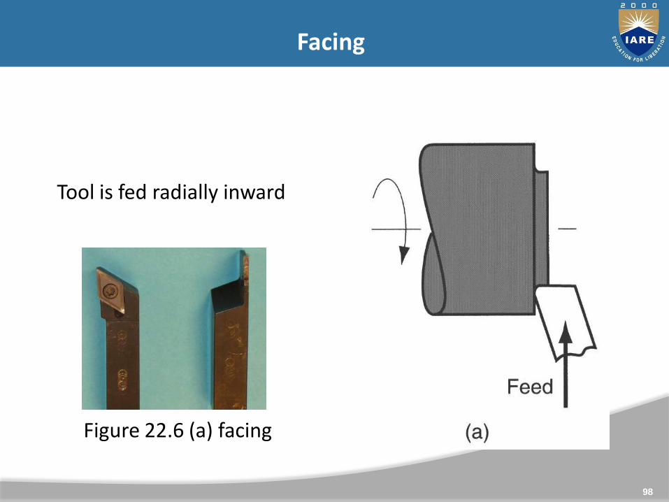
Facing
Figure 22.6 (a) facing
Tool is fed radially inward
99
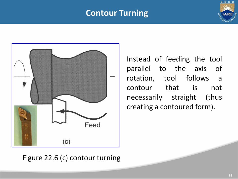
Contour Turning
Instead of feeding the toolparallel to the axis ofrotation, tool follows acontour that is notnecessarily straight (thuscreating a contoured form).
Figure 22.6 (c) contour turning
100
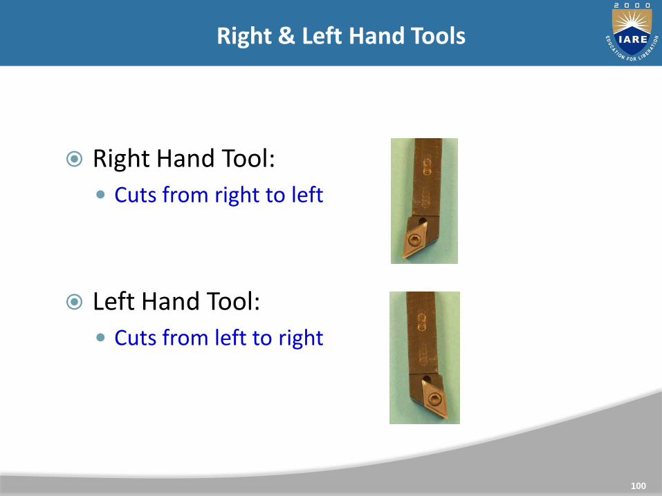
Right & Left Hand Tools
Right Hand Tool:
Cuts from right to left
Left Hand Tool:
Cuts from left to right
101
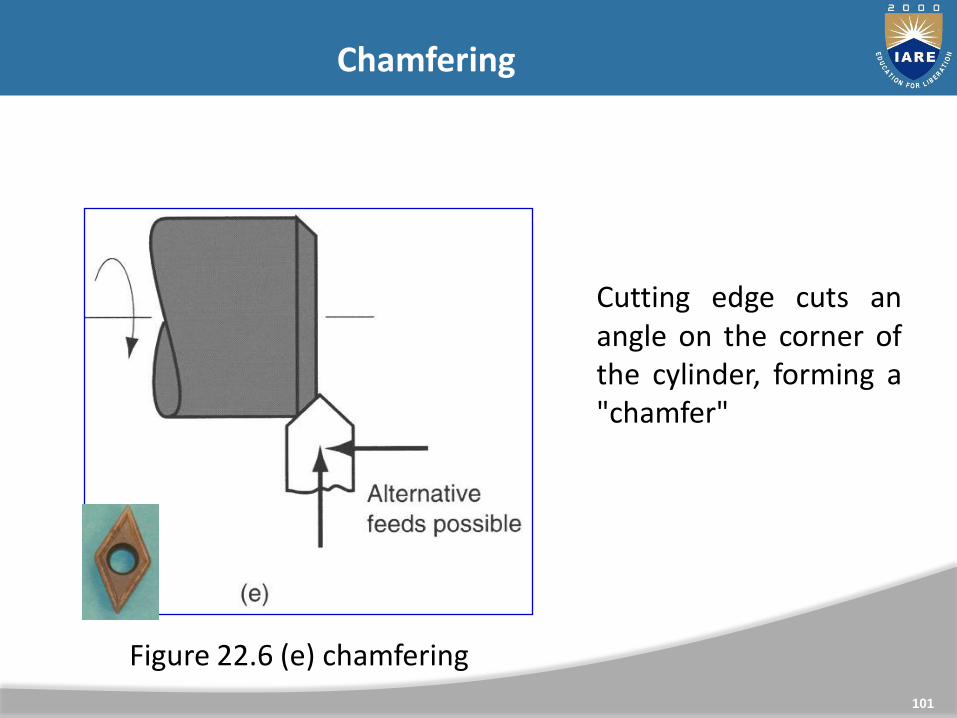
Chamfering
Cutting edge cuts anangle on the corner ofthe cylinder, forming a"chamfer"
Figure 22.6 (e) chamfering
102
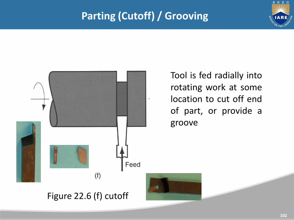
Parting (Cutoff) / Grooving
Tool is fed radially intorotating work at somelocation to cut off endof part, or provide agroove
Figure 22.6 (f) cutoff
103
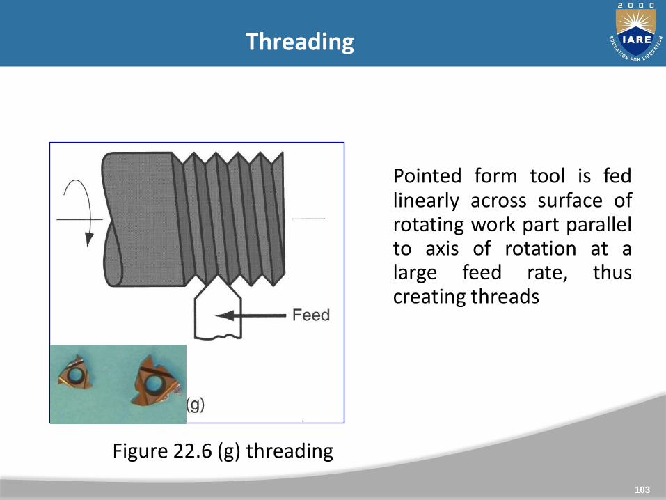
Threading
Pointed form tool is fedlinearly across surface ofrotating work part parallelto axis of rotation at alarge feed rate, thuscreating threads
Figure 22.6 (g) threading

104
Machining Calculations: Turning
Spindle Speed - N (rpm)
○ v = cutting speed
○ Do = outer diameter
Feed Rate - fr (mm/min -or- in/min)
○ f = feed per rev
Depth of Cut - d (mm/rev -or- in/rev)
○ Do = outer diameter
○ Df = final diameter
Machining Time - Tm (min)
○ L = length of cut
Mat’l Removal Rate - MRR (mm3/min -or- in3/min)
oDπ
vN
L
DDd
fo
2
r
mf
LT
fNf r
dfvM R R
105
UNIT - III
MACHINE TOOL-II
106
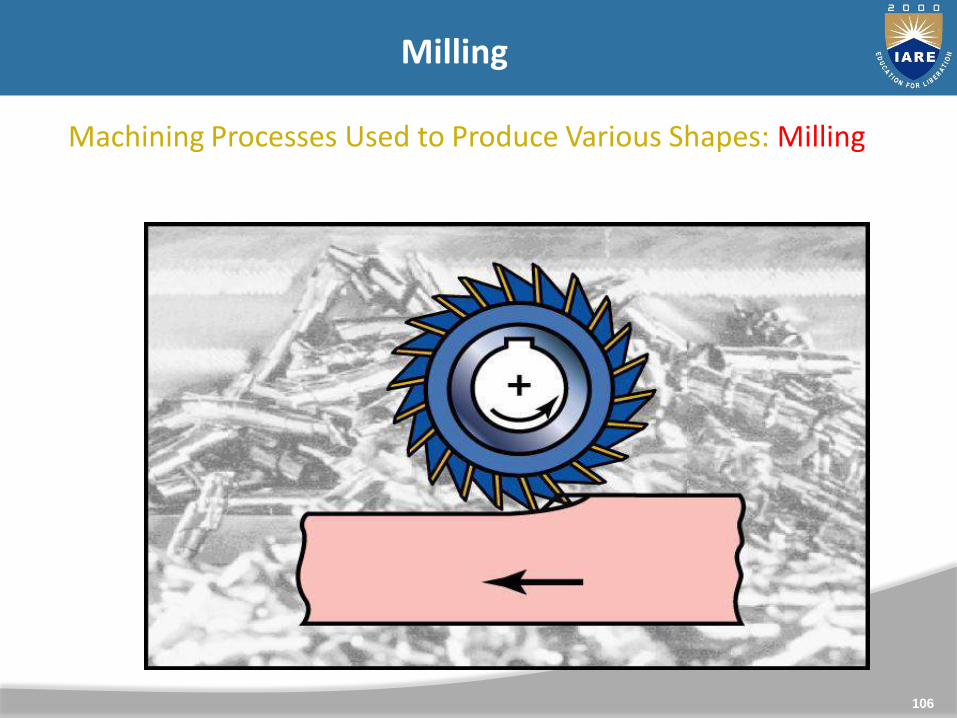
Machining Processes Used to Produce Various Shapes: Milling
Milling
107
Milling and Milling Machines, Milling operations
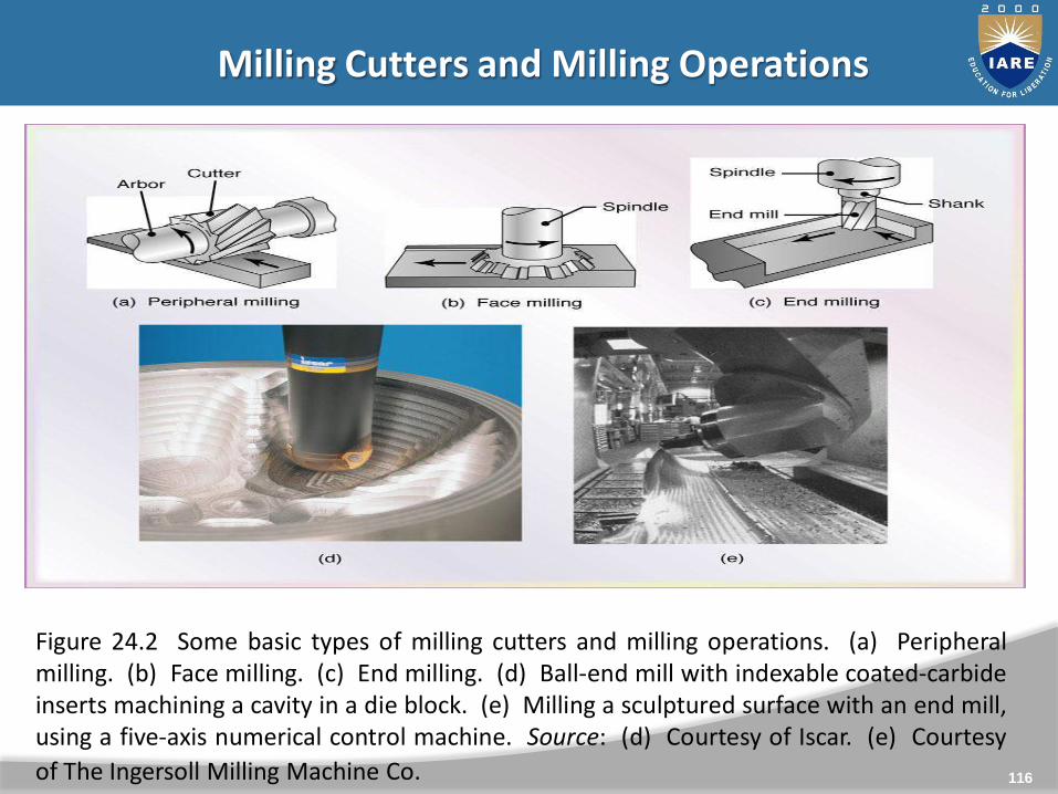
Milling: a process in which a rotating multi-tooth cutter removes
material while traveling along various axes with respect to thework-piece.
Figure shows basic types of milling cutters & millingoperations
In peripheral milling (also called plain milling), the axis ofcutter rotation is parallel to the work-piece surface.
When the cutter is longer than the width of the cut, theprocess is called slab milling
108
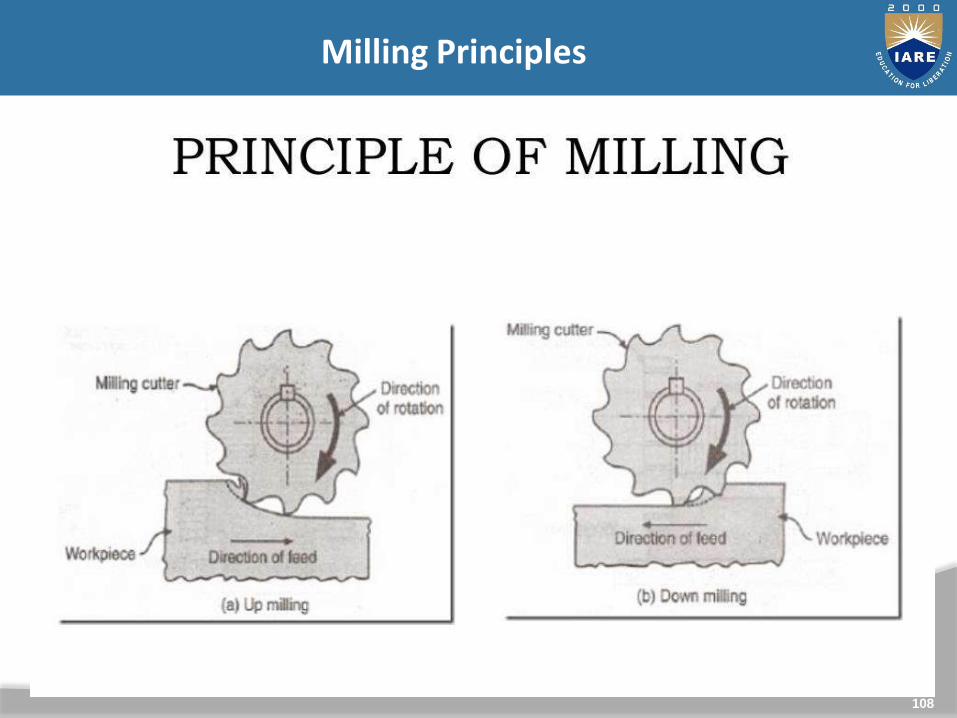
Milling Principles
109
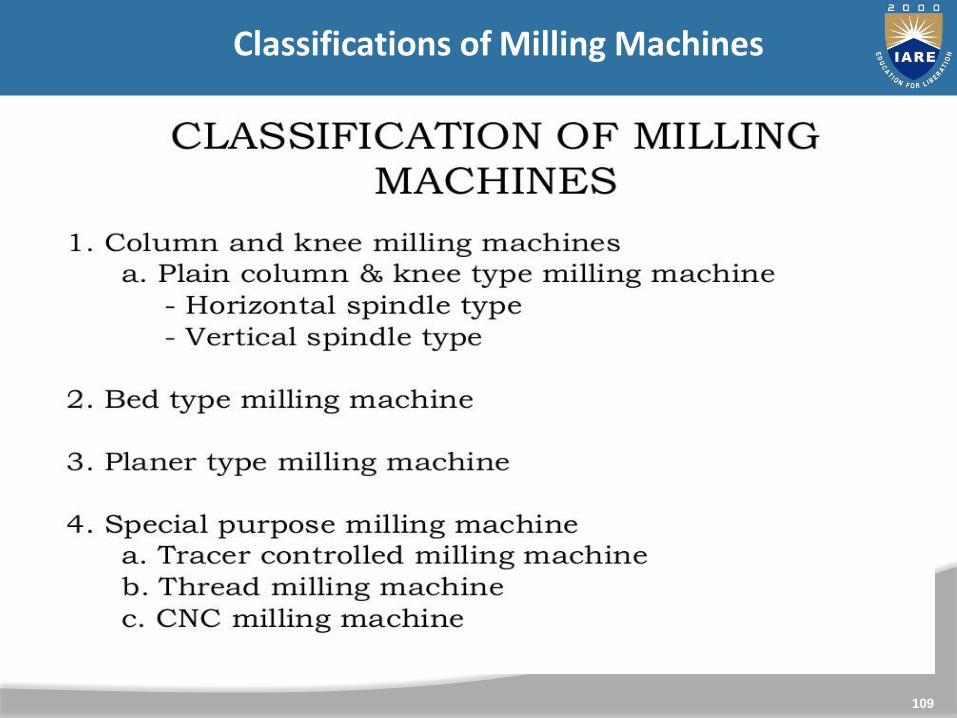
Classifications of Milling Machines
110
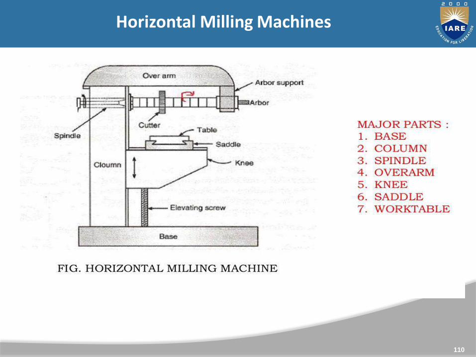
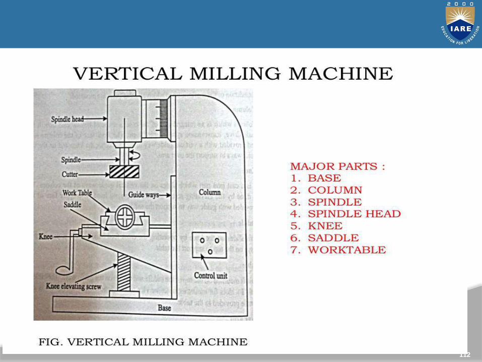
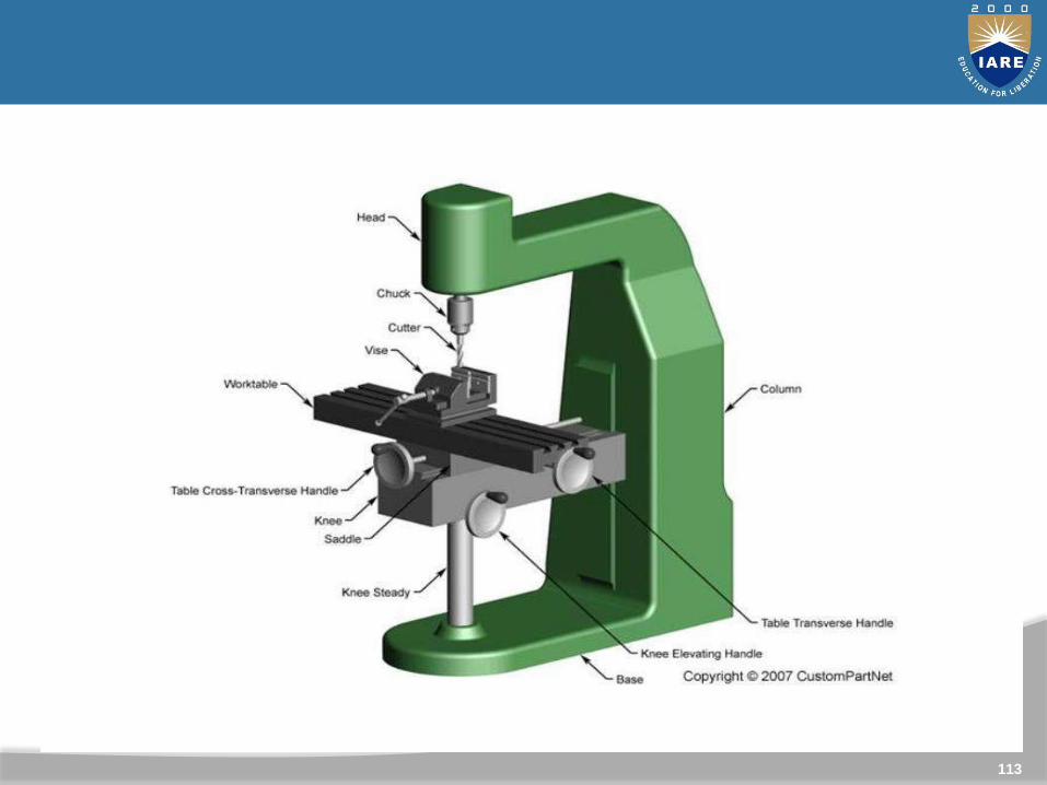
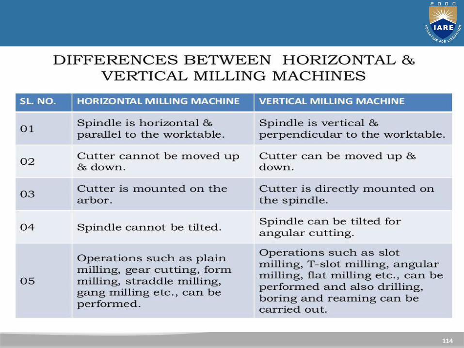
Horizontal Milling Machines
111
112
113
114
115
116
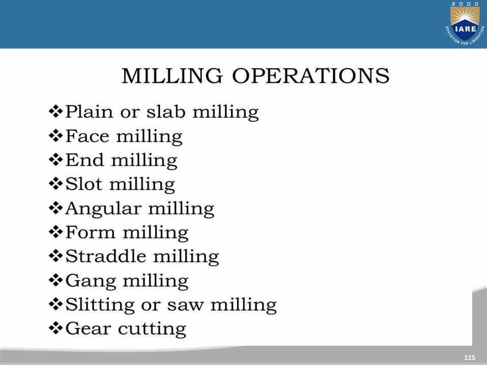
Milling Cutters and Milling Operations
Figure 24.2 Some basic types of milling cutters and milling operations. (a) Peripheralmilling. (b) Face milling. (c) End milling. (d) Ball-end mill with indexable coated-carbideinserts machining a cavity in a die block. (e) Milling a sculptured surface with an end mill,using a five-axis numerical control machine. Source: (d) Courtesy of Iscar. (e) Courtesy
of The Ingersoll Milling Machine Co.
117
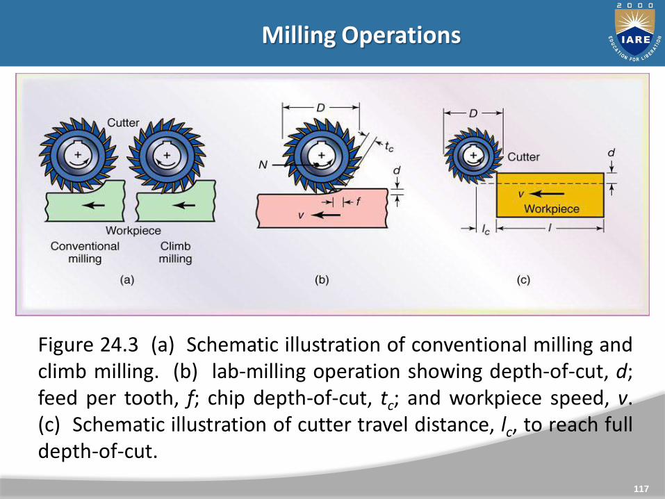
Milling Operations
Figure 24.3 (a) Schematic illustration of conventional milling andclimb milling. (b) lab-milling operation showing depth-of-cut, d;feed per tooth, f; chip depth-of-cut, tc; and workpiece speed, v.(c) Schematic illustration of cutter travel distance, lc, to reach fulldepth-of-cut.

118
Milling operations: up milling
Conventional Milling (Up Milling)
Max chip thickness is at the end of the cut Advantage: tooth engagement is not a function of work piece
surface characteristics, and contamination or scale on thesurface does not affect tool life.
Cutting process is smooth Tendency for the tool to chatter The work piece has a tendency to be pulled upward,
necessitating proper clamping.

119
Climb Milling (Down Milling)
Cutting starts at the surface of the work piece.
Downward compression of cutting forces hold work piece inplace
Because of the resulting high impact forces when the teethengage the work piece, this operation must have a rigidsetup, and backlash must be eliminated in the table feedmechanism
Not suitable for machining work piece having surface scale.
Milling and Milling MachinesMilling operations: Down milling

120
Milling Parameters

121
Numericals
EXAMPLE 24.1 Material-removal Rate, Power, Torque, and
Cutting Time in Slab Milling
A slab-milling operation is being carried out on a 300-mm-long,
100-mm-wide annealed mild-steel block at a feed f = 0.25
mrn/tooth and a depth of cut d = 3.0 mm. The cutter is D = 50 mm
in diameter, has 20 straight teeth, rotates at N = 100 rpm, and, by
definition, is wider than the block to be machined, Calculate the
material-removal rate, estimate the power and torque required for
this operation, and calculate the cutting time.
Solution:
From table 21.2 U=3 W.S/mm3

122
123
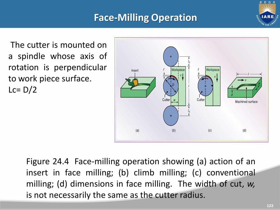
Face-Milling Operation
Figure 24.4 Face-milling operation showing (a) action of aninsert in face milling; (b) climb milling; (c) conventionalmilling; (d) dimensions in face milling. The width of cut, w,is not necessarily the same as the cutter radius.
The cutter is mounted ona spindle whose axis ofrotation is perpendicularto work piece surface.Lc= D/2
124
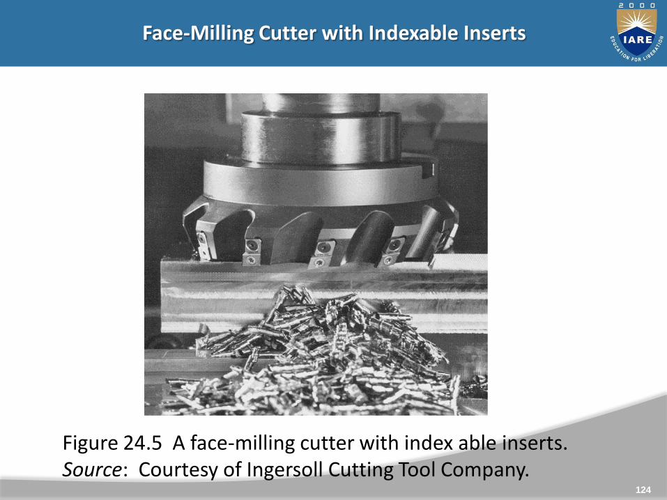
Face-Milling Cutter with Indexable Inserts
Figure 24.5 A face-milling cutter with index able inserts. Source: Courtesy of Ingersoll Cutting Tool Company.

125
Effect of Insert Shape on Feed Marks on a Face-Milled Surface
Figure 24.6 Schematic illustration of the effect of insert shape onfeed marks on a face-milled surface: (a) small corner radius, (b)corner flat on insert, and (c) wiper, consisting of small radiusfollowed by a large radius which leaves smoother feed marks. (d)Feed marks due to various insert shapes.
126
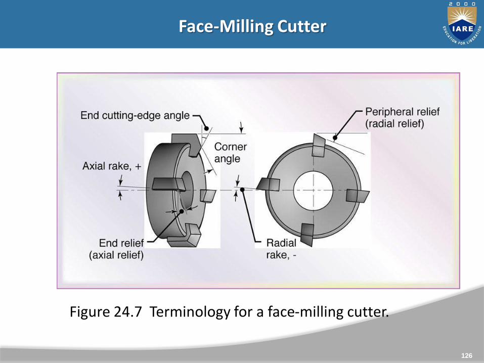
Face-Milling Cutter
Figure 24.7 Terminology for a face-milling cutter.
127
Effect of Lead Angle on Un deformed Chip Thickness in Face Milling
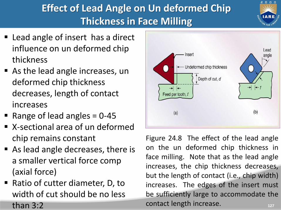
Figure 24.8 The effect of the lead angleon the un deformed chip thickness inface milling. Note that as the lead angleincreases, the chip thickness decreases,but the length of contact (i.e., chip width)increases. The edges of the insert mustbe sufficiently large to accommodate thecontact length increase.
Lead angle of insert has a direct influence on un deformed chip thickness
As the lead angle increases, un deformed chip thickness decreases, length of contact increases
Range of lead angles = 0-45 X-sectional area of un deformed
chip remains constant As lead angle decreases, there is
a smaller vertical force comp (axial force)
Ratio of cutter diameter, D, to width of cut should be no less than 3:2
128
Position of Cutter and Insert in Face Milling
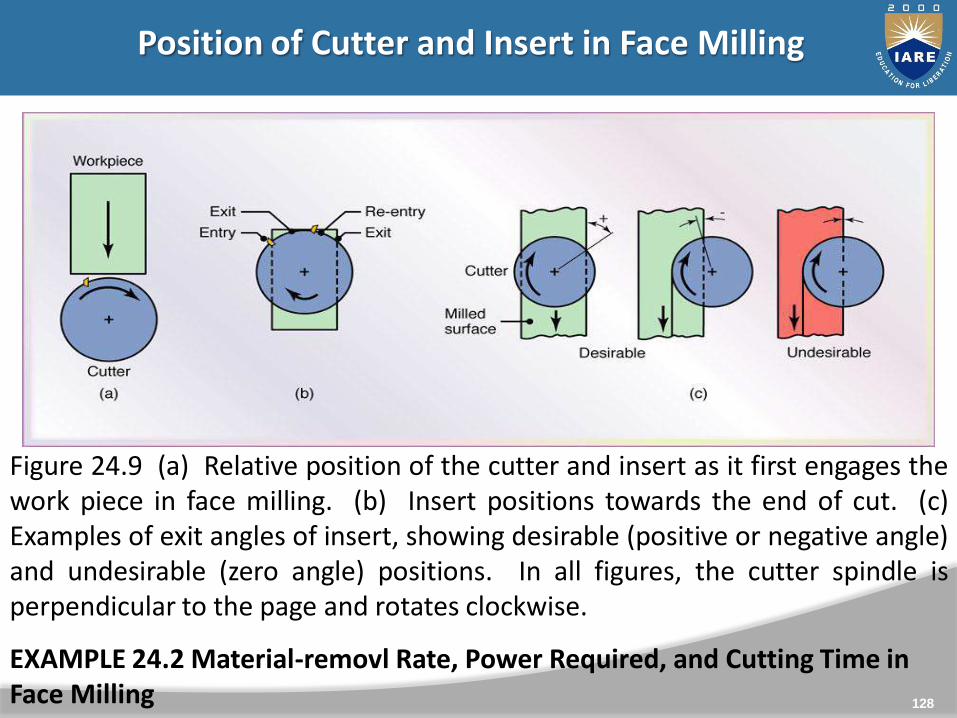
Figure 24.9 (a) Relative position of the cutter and insert as it first engages thework piece in face milling. (b) Insert positions towards the end of cut. (c)Examples of exit angles of insert, showing desirable (positive or negative angle)and undesirable (zero angle) positions. In all figures, the cutter spindle isperpendicular to the page and rotates clockwise.
EXAMPLE 24.2 Material-removl Rate, Power Required, and Cutting Time in Face Milling
129
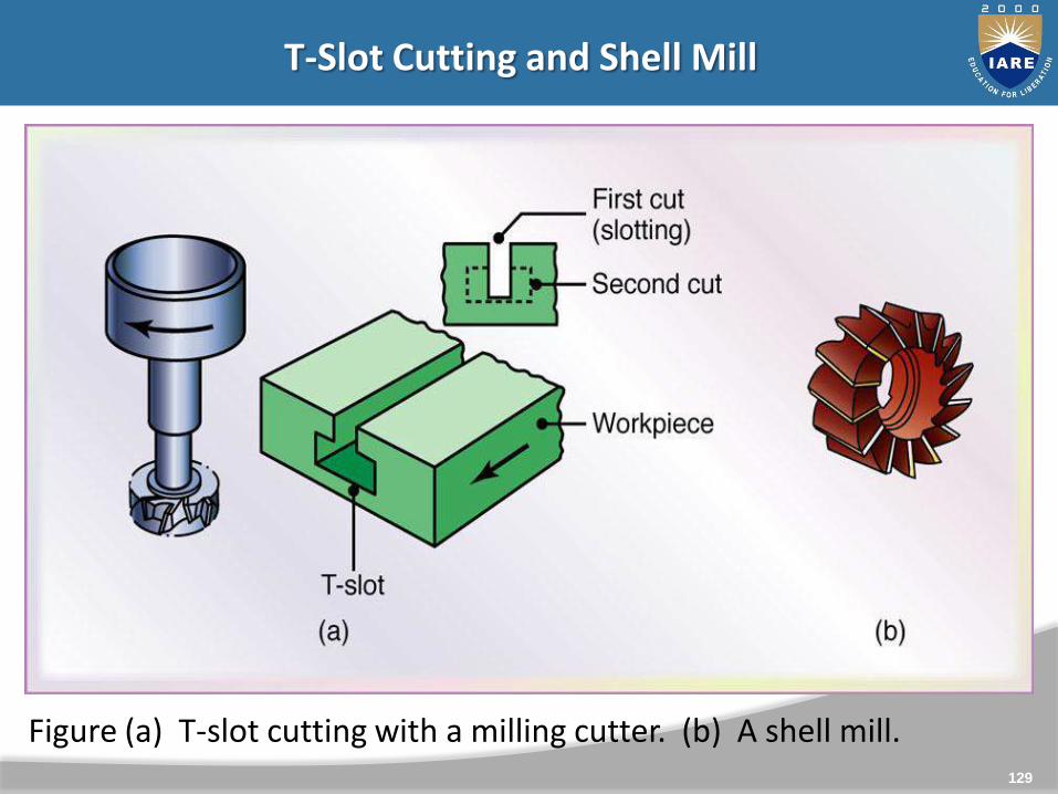
T-Slot Cutting and Shell Mill
Figure (a) T-slot cutting with a milling cutter. (b) A shell mill.
130
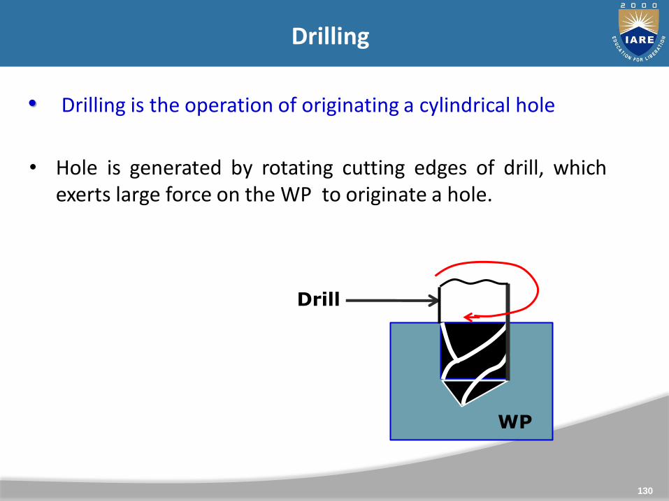
Drilling
• Drilling is the operation of originating a cylindrical hole
• Hole is generated by rotating cutting edges of drill, whichexerts large force on the WP to originate a hole.
WP
Drill
131
Principle of Drilling Machine
Drilling is an operation of generating a hole of differentdiameters by means of rotating cutting tools of differentdiameters. The tool used for drilling hole is called as drill.
Similar operations like boring, reaming, counter boring,counter sinking, tapping etc. are also performed with thedrilling machine.
This is done by holding the tools rigidly in the tool holdingdevice know as Chuck. Thus in this machining operation thetool is rotating one while the work piece is stationary one,which rests on the working table.

132
Types of Drilling Machines
• Portable Drilling Machine• Sensitive Drilling Machine• Pillar/Upright Drilling Machine• Radial Drilling Machine• Gang Drilling Machine• Multiple Spindle Drilling Machine• Automatic Drilling Machine• Deep Hole Drilling Machine• Portable Drilling machine
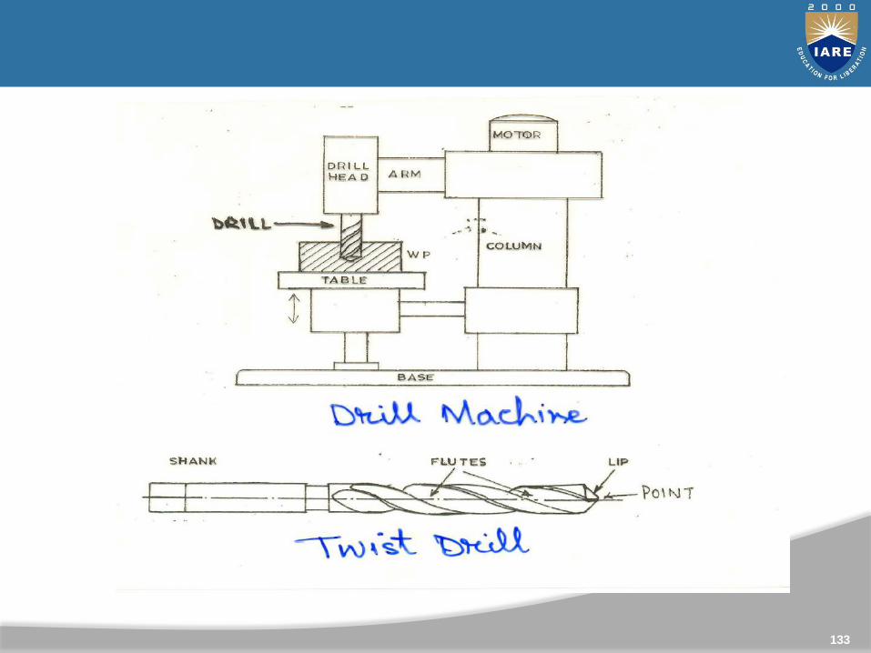
133
134
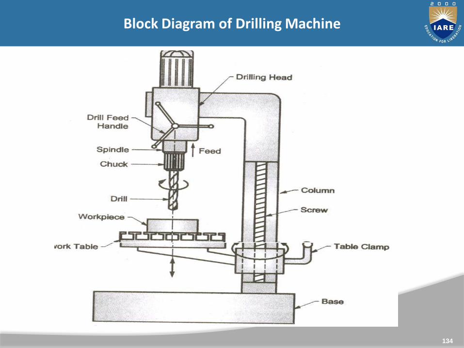
Block Diagram of Drilling Machine
135
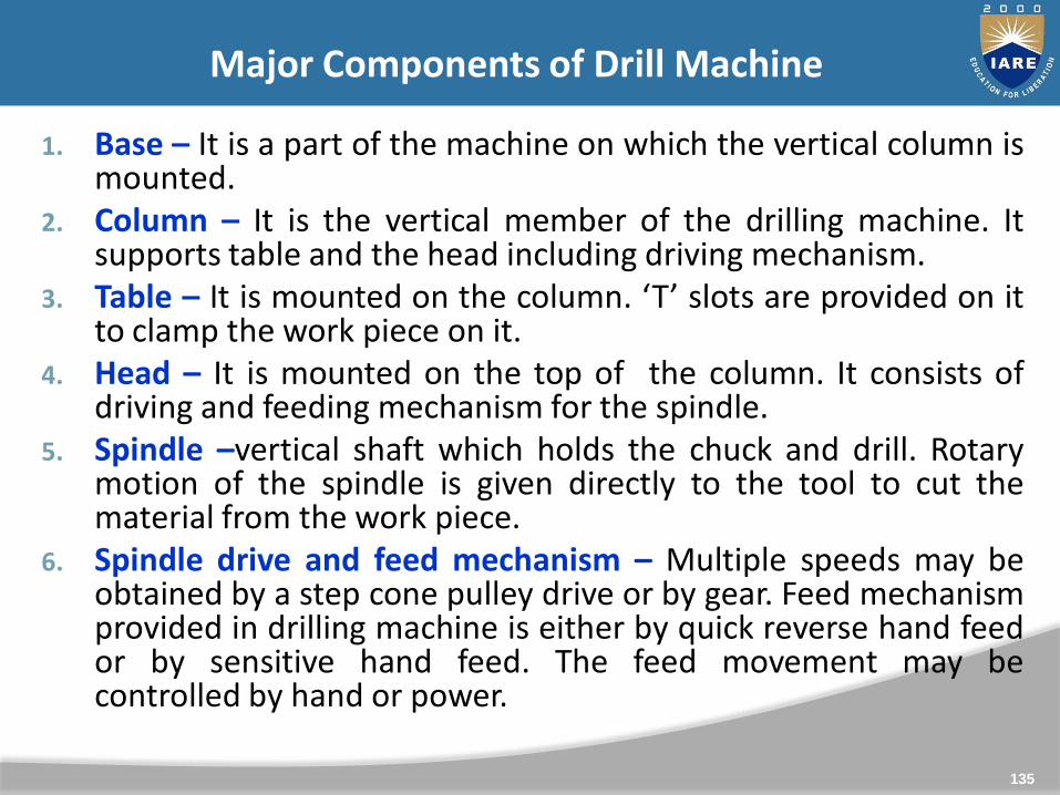
1. Base – It is a part of the machine on which the vertical column ismounted.
2. Column – It is the vertical member of the drilling machine. Itsupports table and the head including driving mechanism.
3. Table – It is mounted on the column. ‘T’ slots are provided on itto clamp the work piece on it.
4. Head – It is mounted on the top of the column. It consists ofdriving and feeding mechanism for the spindle.
5. Spindle –vertical shaft which holds the chuck and drill. Rotarymotion of the spindle is given directly to the tool to cut thematerial from the work piece.
6. Spindle drive and feed mechanism – Multiple speeds may beobtained by a step cone pulley drive or by gear. Feed mechanismprovided in drilling machine is either by quick reverse hand feedor by sensitive hand feed. The feed movement may becontrolled by hand or power.
Major Components of Drill Machine
136
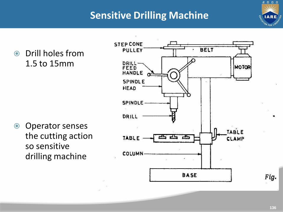
Sensitive Drilling Machine
Drill holes from 1.5 to 15mm
Operator senses the cutting action so sensitive drilling machine
137
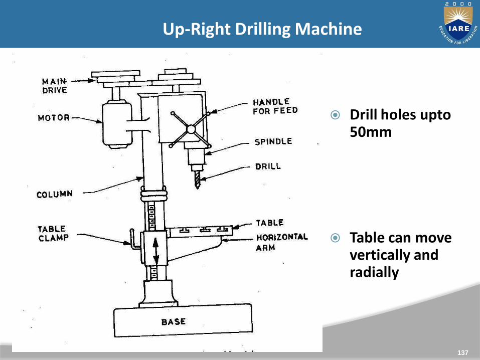
Up-Right Drilling Machine
Drill holes upto50mm
Table can move vertically and radially
138
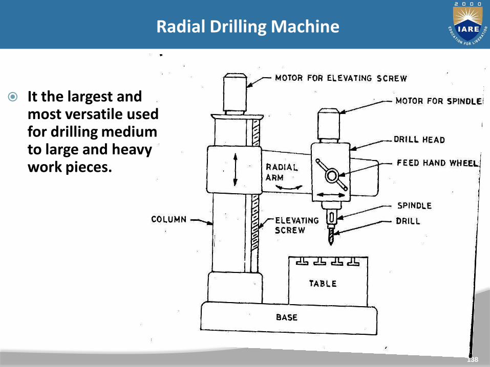
Radial Drilling Machine
It the largest and most versatile used for drilling medium to large and heavy work pieces.

UNIT-IV
139
GEOMETRICAL DIMENSIONING AND TOLERANCES

Metrology is the science of measurement
Dimensional metrology is that branch of Metrology which dealswith measurement of “dimensions” of a part or workpiece(lengths, angles, etc.)
Dimensional measurements at the required level of accuracyare the essential link between the designers intent and adelivered product.
140
Metrology
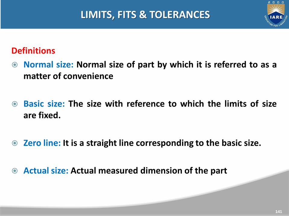
Definitions
Normal size: Normal size of part by which it is referred to as amatter of convenience
Basic size: The size with reference to which the limits of sizeare fixed.
Zero line: It is a straight line corresponding to the basic size.
Actual size: Actual measured dimension of the part
141
LIMITS, FITS & TOLERANCES
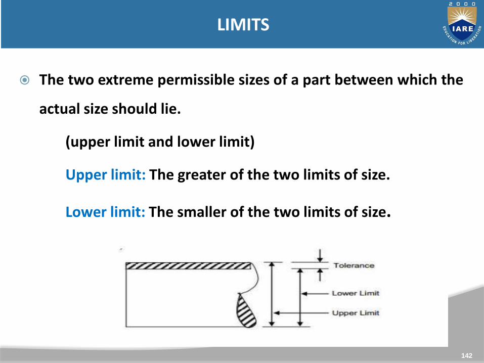
The two extreme permissible sizes of a part between which the
actual size should lie.
(upper limit and lower limit)
Upper limit: The greater of the two limits of size.
Lower limit: The smaller of the two limits of size.
142
LIMITS

It is the difference between the upper and lower limits
tolerance = upper limit – lower limit
143
TOLERANCES

Why it is necessary?
It is impossible to manufacture a part or component to an exact size or geometry.
Since variation from the drawing is inevitable, acceptable degree of variation must be applied.
Large variation may affect the functionality of the part.
Small variation may effect the economy of the part.
144

It is the difference between the basic dimensions of the matingparts
When the shaft size is less than the hole size, then theallowance is positive and when the shaft size is greater thanthe hole size, then the allowance is negative.
145
ALLOWANCES

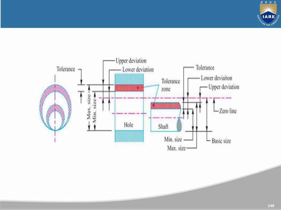
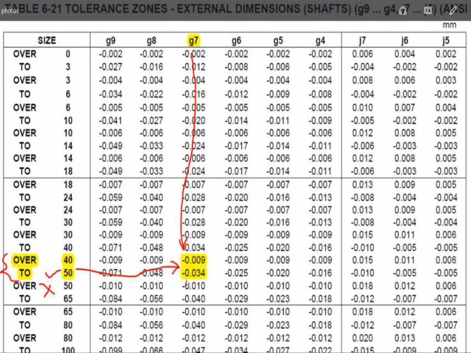
Tolerance Zone: It is the zone between the maximum andminimum limit size.
Upper Deviation: It is the algebraic difference between themaximum size and the basic size.
Lower Deviation: It is the algebraic difference between the
minimum size and the basic size.
146
Definitions

147
148

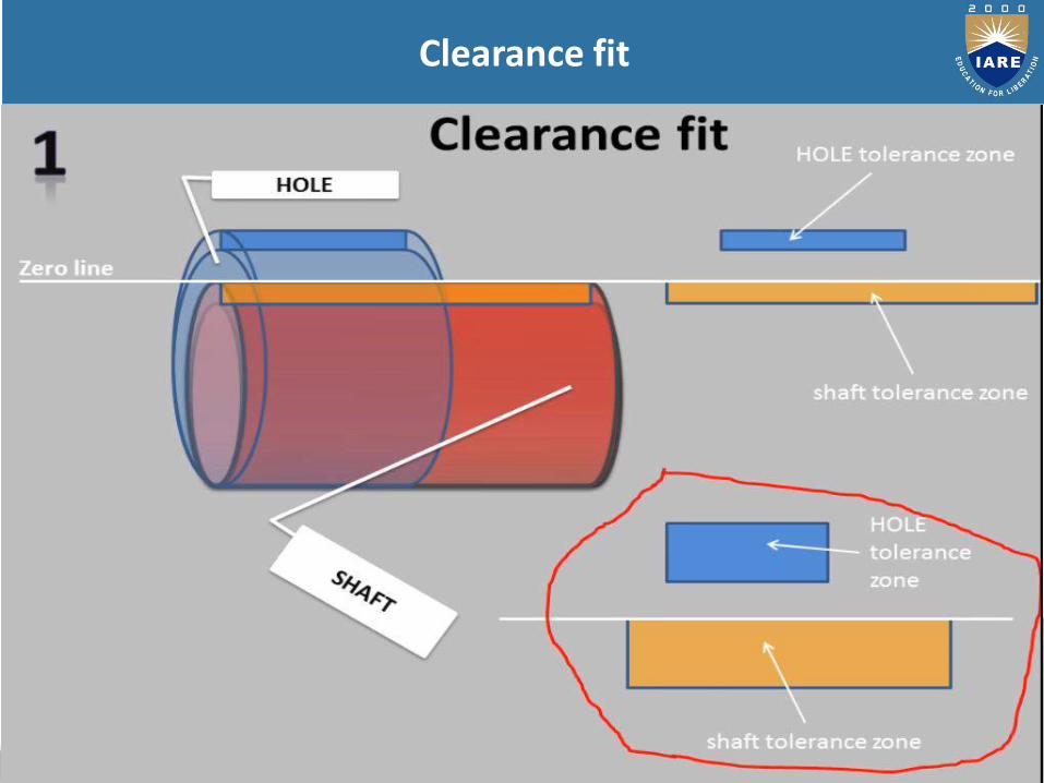
If it is the degree of looseness or tightness between two mating parts to perform a definite function.
1. Clearance fit
2. Transition fit
3. Interference fit
149
FIT
150
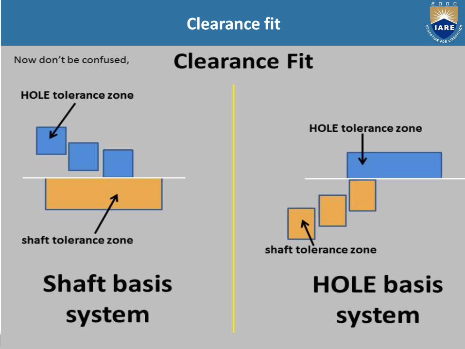
Clearance fit
151
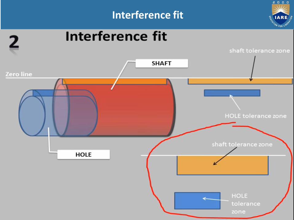
Interference fit
152
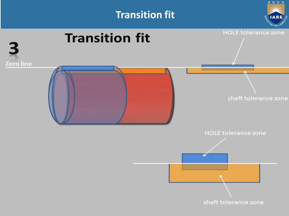
Transition fit

153
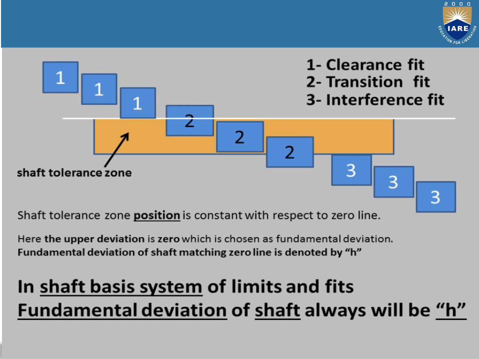
SHAFT BASIS SYSTEM
154

155
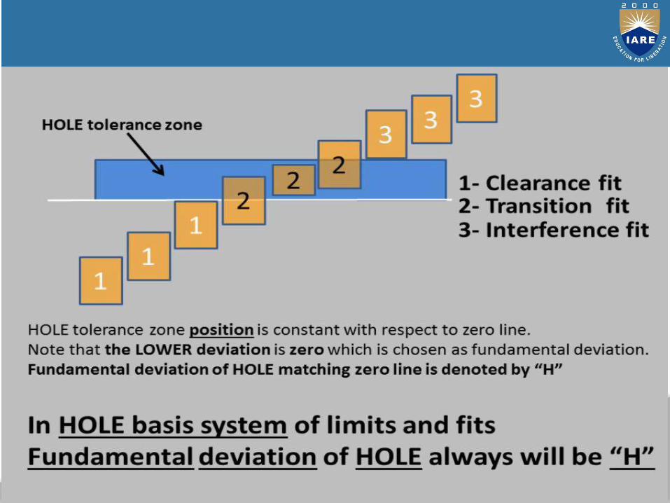
HOLE BASIS SYSTEM
156
157
Clearance fit

158
Interference fit
159
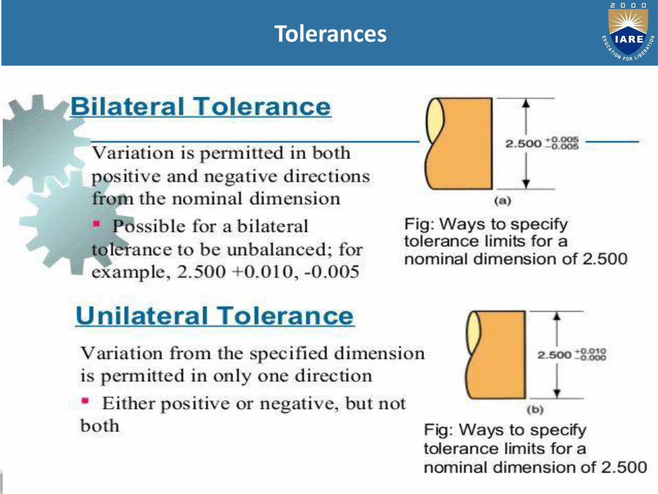
Tolerances
160
161
162
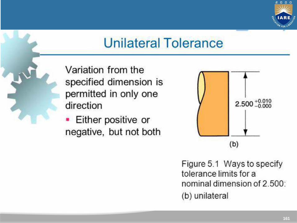
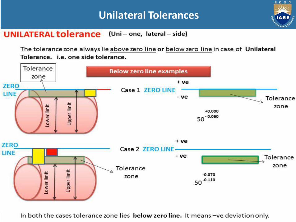
Unilateral Tolerances

163

164
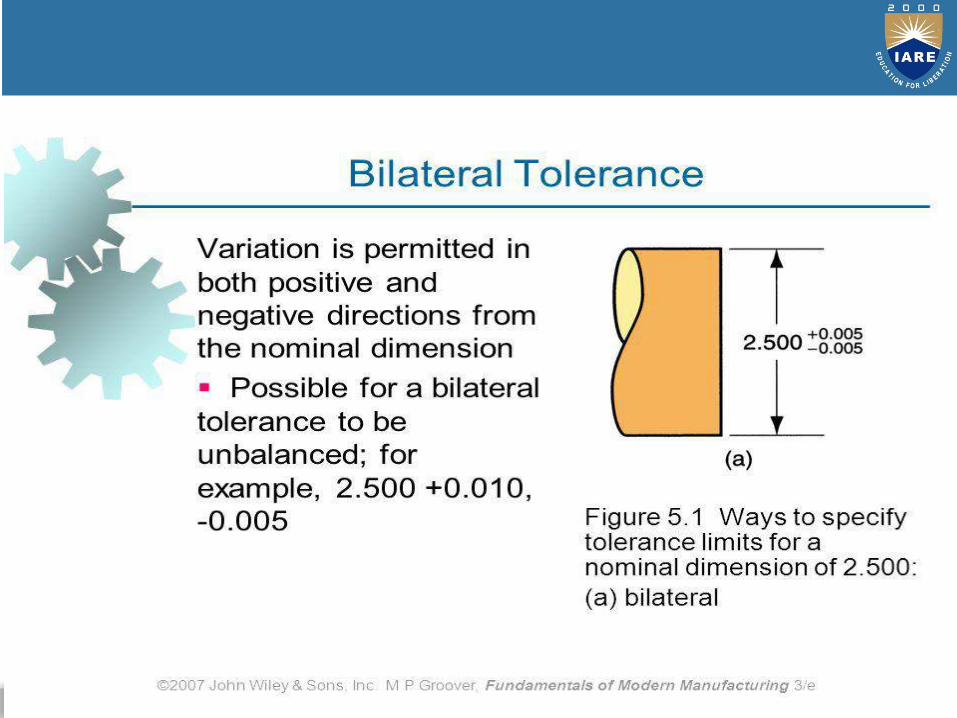
Bilateral Tolerances
(Bi-Two, lateral-side)
The tolerance zone always lie on both sides of aero line.
(above zero line & below zero line)
It is not necessary that zero line will divide tolerance zone equallyon both sides, it may be equal or unequal.
165
BILATERAL TOLERANCE

Deviation: It is the algebraic difference between a size and itscorresponding basic size. It may be positive, negative, or zero.
Upper deviation: It is the algebraic difference between themaximum limit of size and its corresponding basic size. This isdesignated as ‘ES’ for a hole and as ‘es’ for a shaft.
Lower deviation: It is the algebraic difference between theminimum limit of size and its corresponding basic size. This isdesignated as ‘EI’ for a hole and as ‘ei’ for a shaft. Actualdeviation: It is the algebraic difference between the actual sizeand its corresponding basic size.
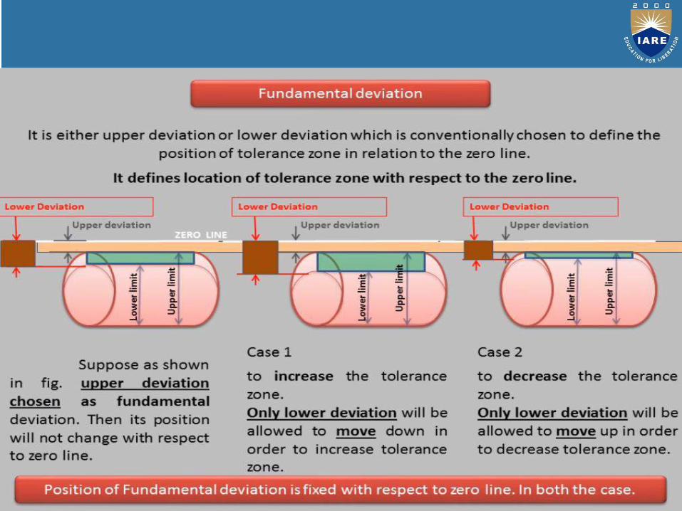
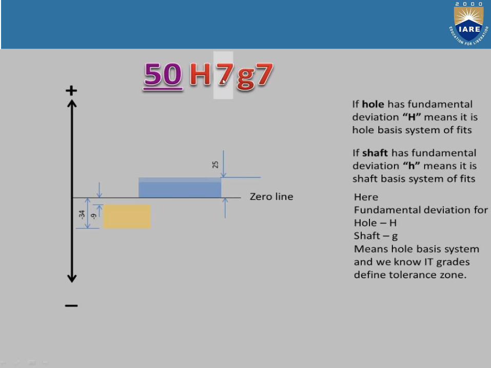
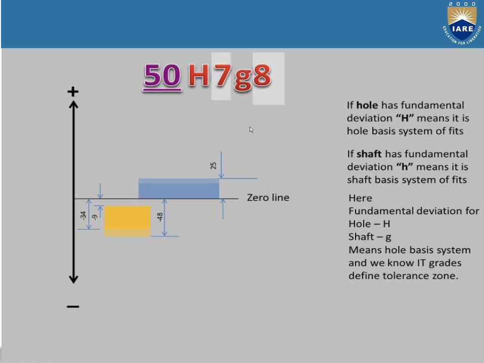
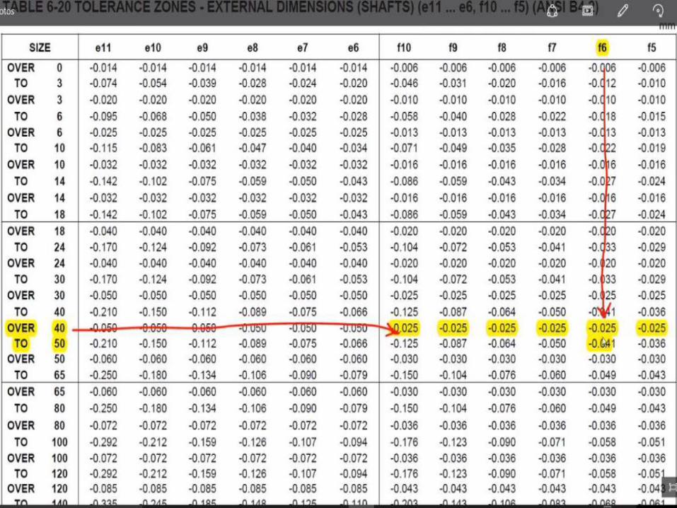
Fundamental deviation: It is the minimum difference betweenthe size of a component and its basic size. This is identical to theupper deviation for shafts and lower deviation for holes.
166

167
168
169

170

171
172

173
174
175
176
177
SLIP GUAGES
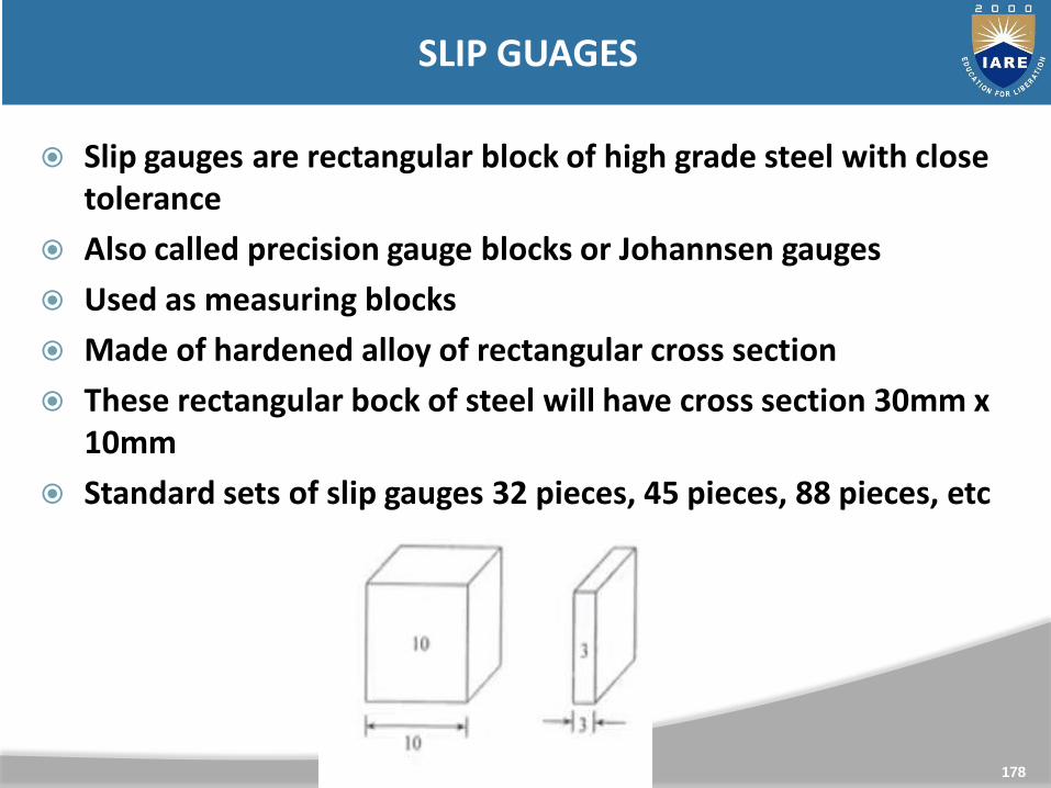
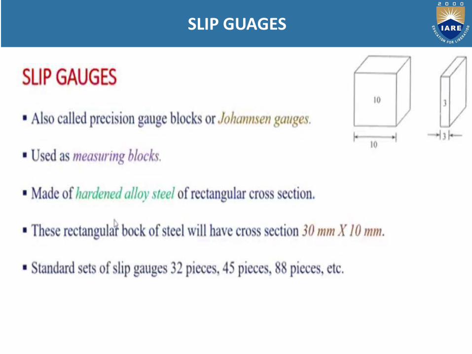
Slip gauges are rectangular block of high grade steel with close tolerance
Also called precision gauge blocks or Johannsen gauges
Used as measuring blocks
Made of hardened alloy of rectangular cross section
These rectangular bock of steel will have cross section 30mm x 10mm
Standard sets of slip gauges 32 pieces, 45 pieces, 88 pieces, etc
178
SLIP GUAGES
179

180
181
Direct precise measurement where accuracy is required
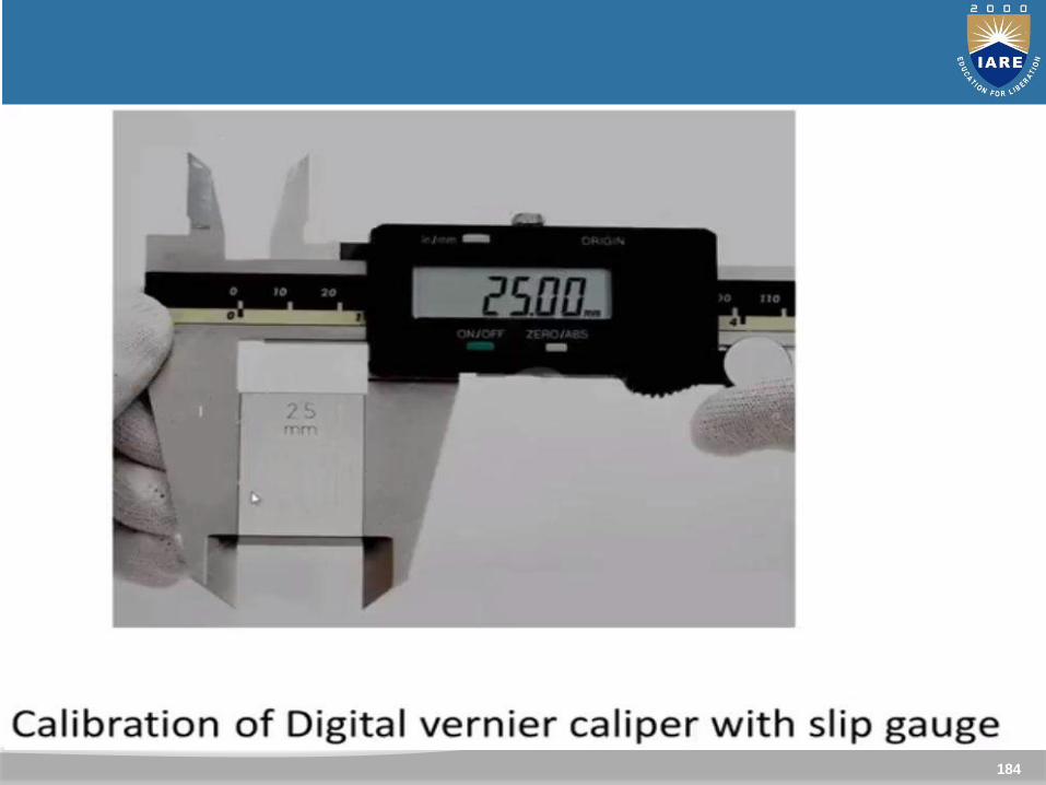
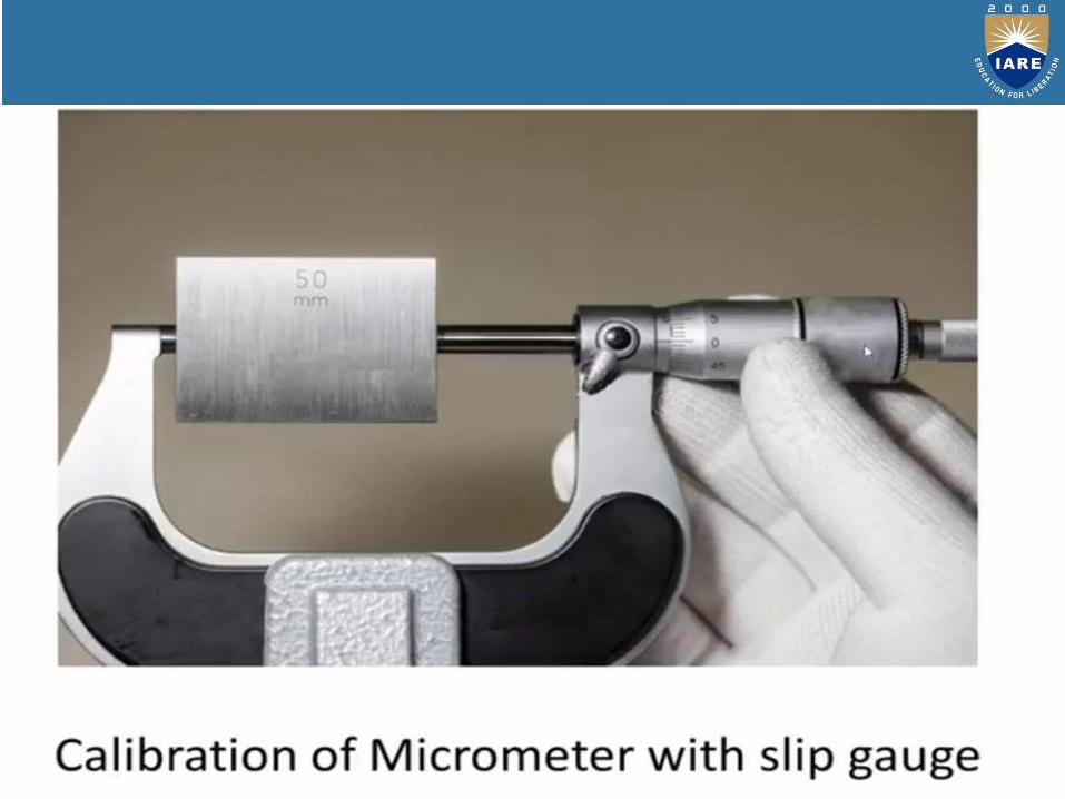
For calibration of Vernier callipers, micrometer etc
Setting up a comparator to a specific dimension
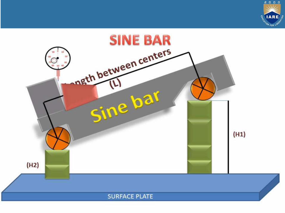
It is used for angle measurement with sine bar
To check gap between parallel locations such as in gap gauges or between 2 mating parts
Some other uses also in manufacturing sector.
182
Uses of Gauge block
183
184
185
186
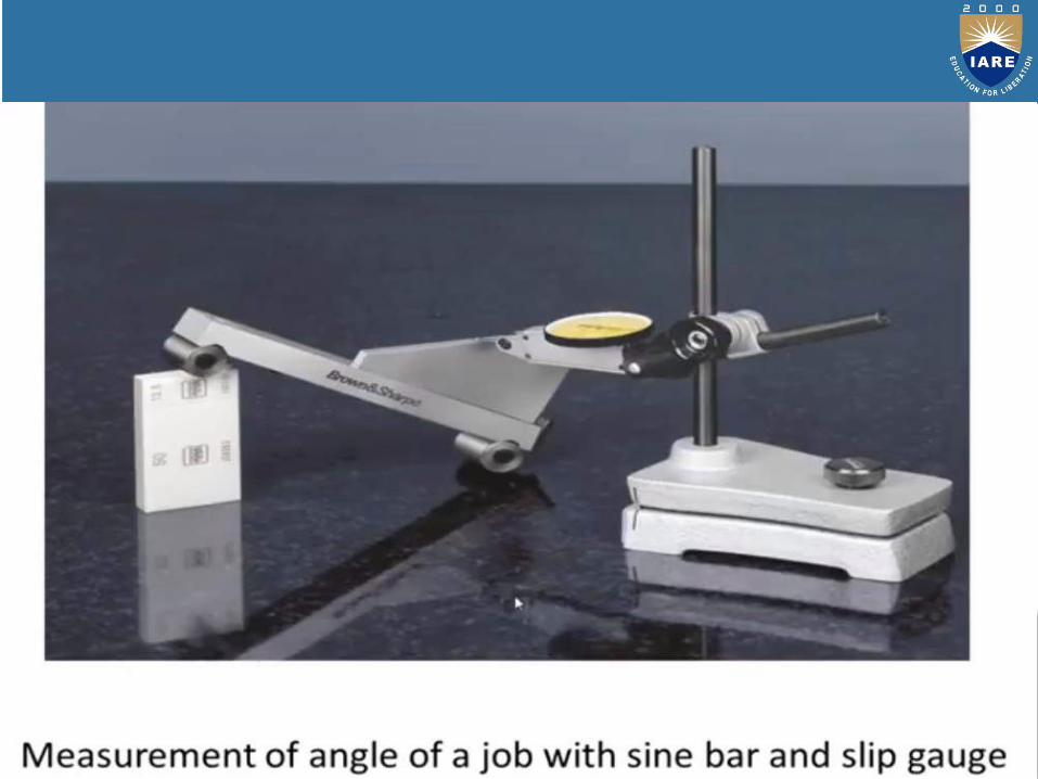
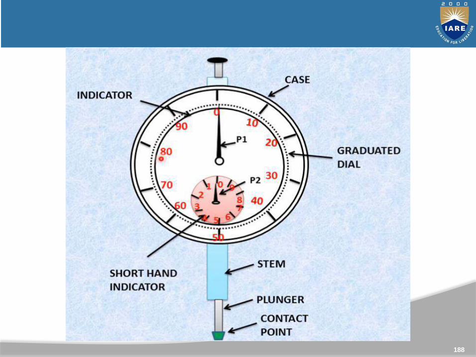
It is used for measuring flatness and inclination of objects
Based on the principle of “Rack and Pinion”
It can measure up to 0.01mm-Least count
187
DIAL GAUGE INDICATOR
188
189
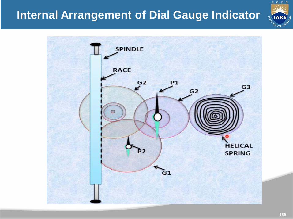
Internal Arrangement of Dial Gauge Indicator
190
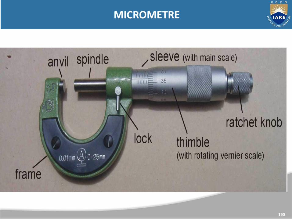
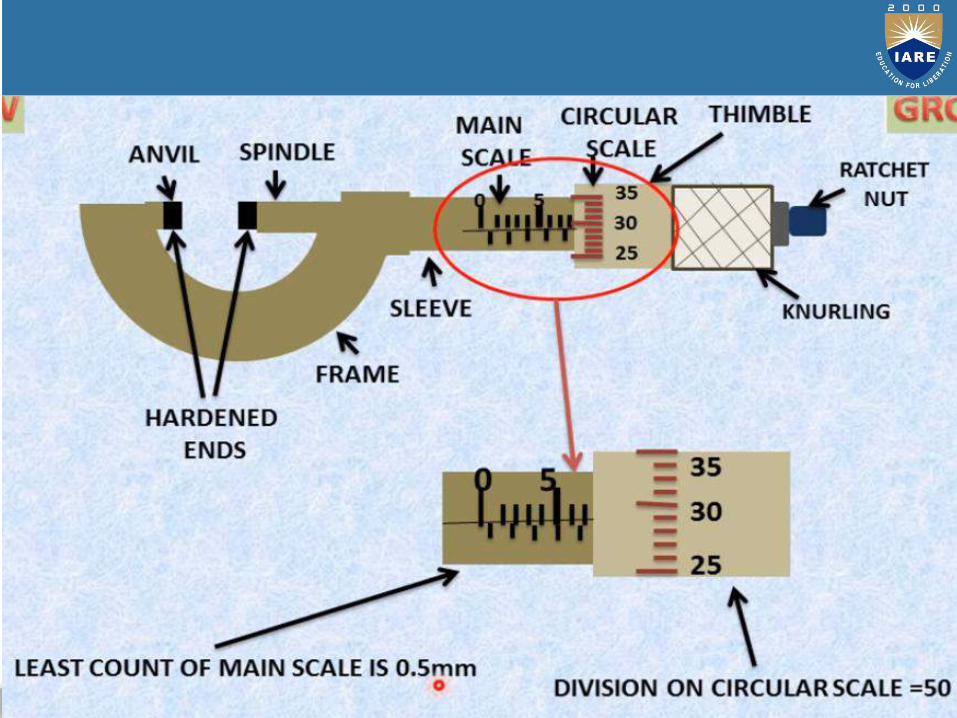
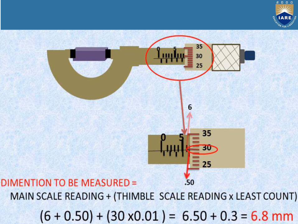
MICROMETRE
191
192

193
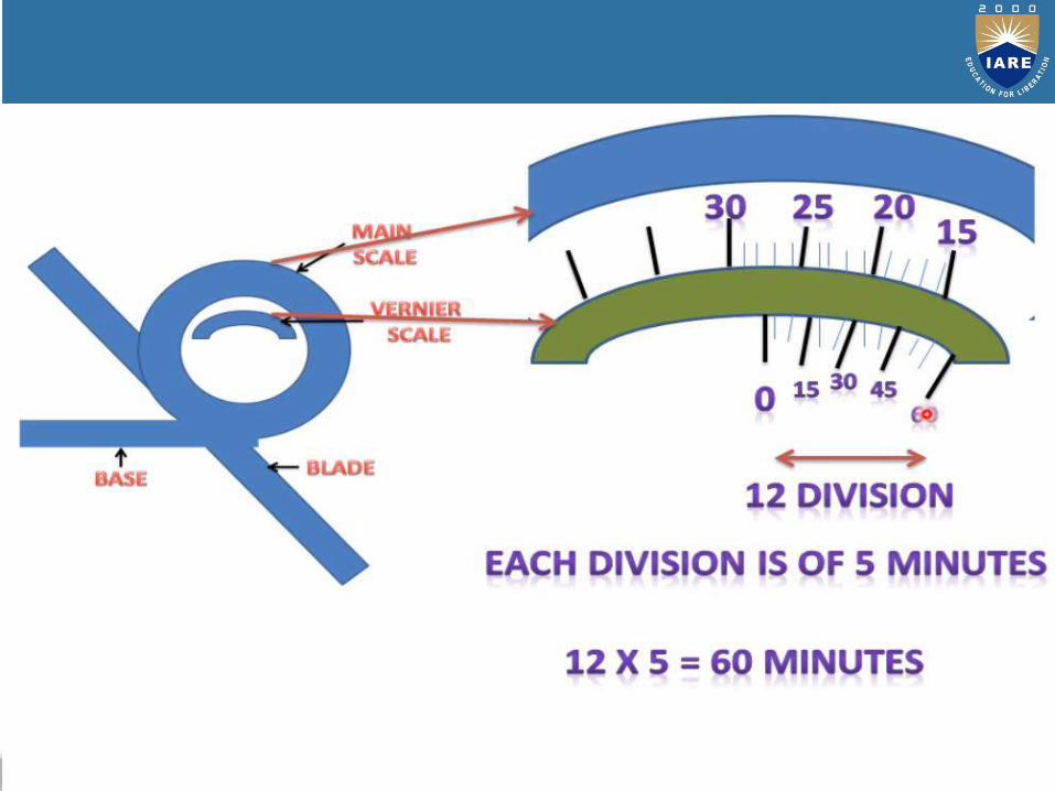
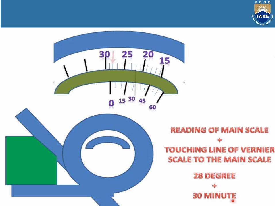
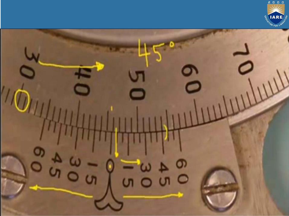
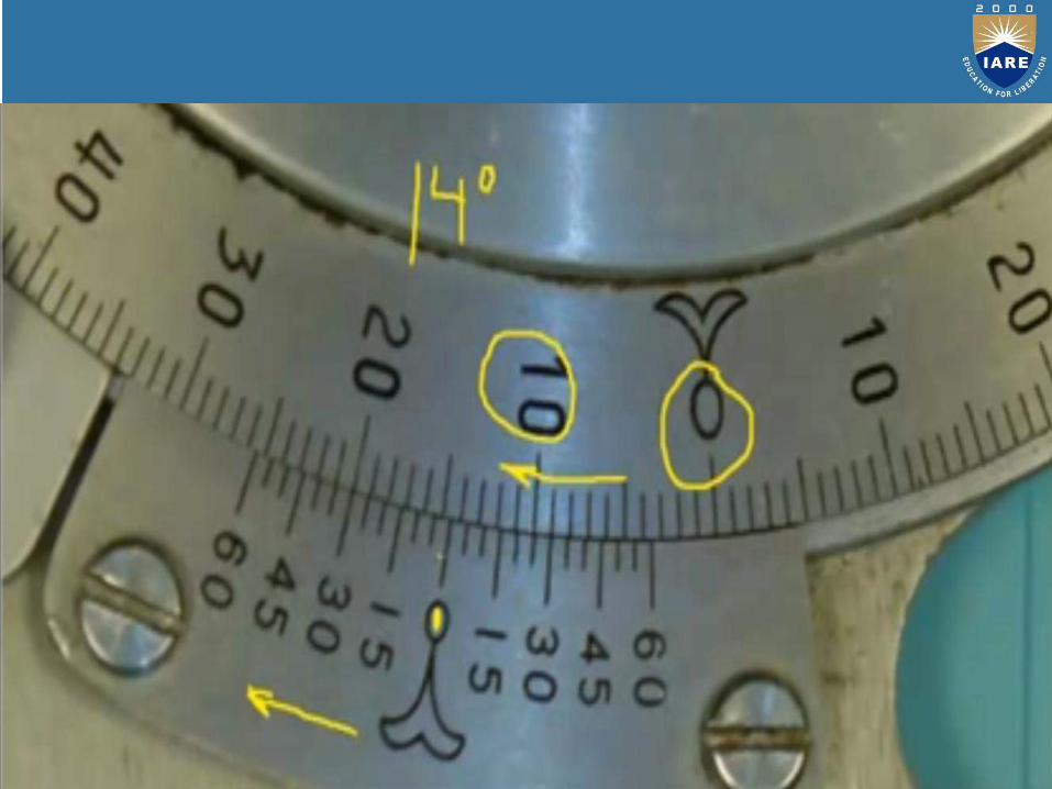
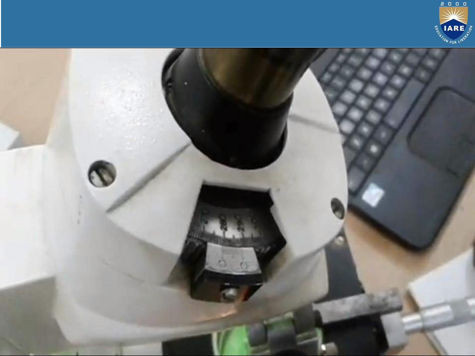
BEVEL PROTRACTOR

194
195
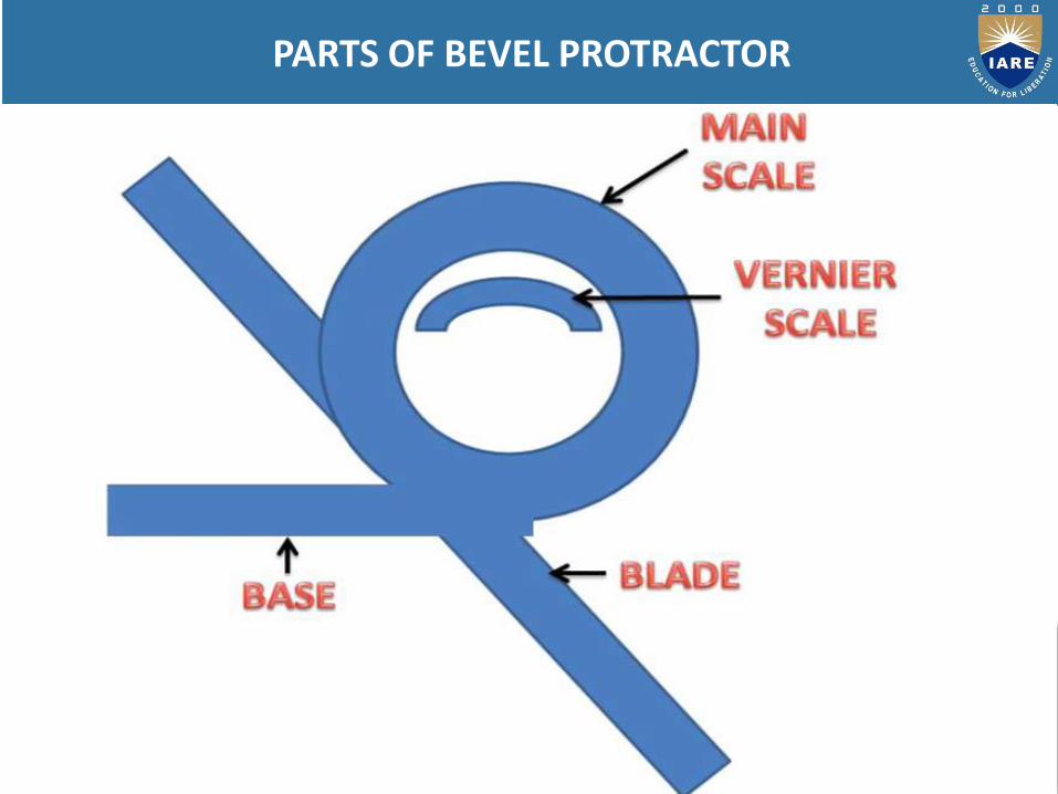
PARTS OF BEVEL PROTRACTOR
196
197

Bevel protractors are nothing but angular measuring instruments.
Types of bevel protractors:
The different types of bevel protractors used are:
1) Vernier bevel protractor
2) Universal protractor
3) Optical protractor
198
199
200

201
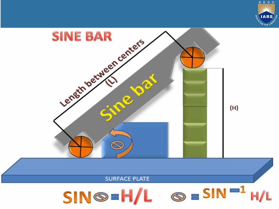
SINE BAR
202

203
204

205
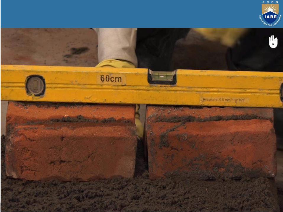
SPIRIT LEVEL
206
MEASURING INSTRUMENTS
207
UNIT-IV
208
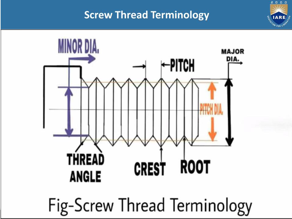
Screw Thread Terminology
209
Measurement of Effective Diameter
1. Thread micrometre method
2. one wire, two wire and three wire method
210
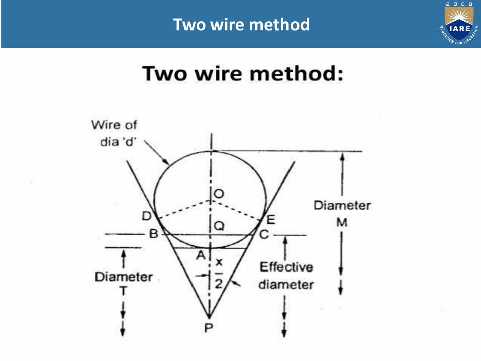
Two wire method
211
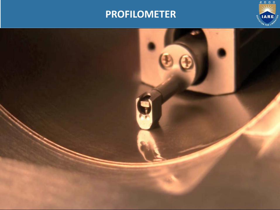
PROFILOMETER
212
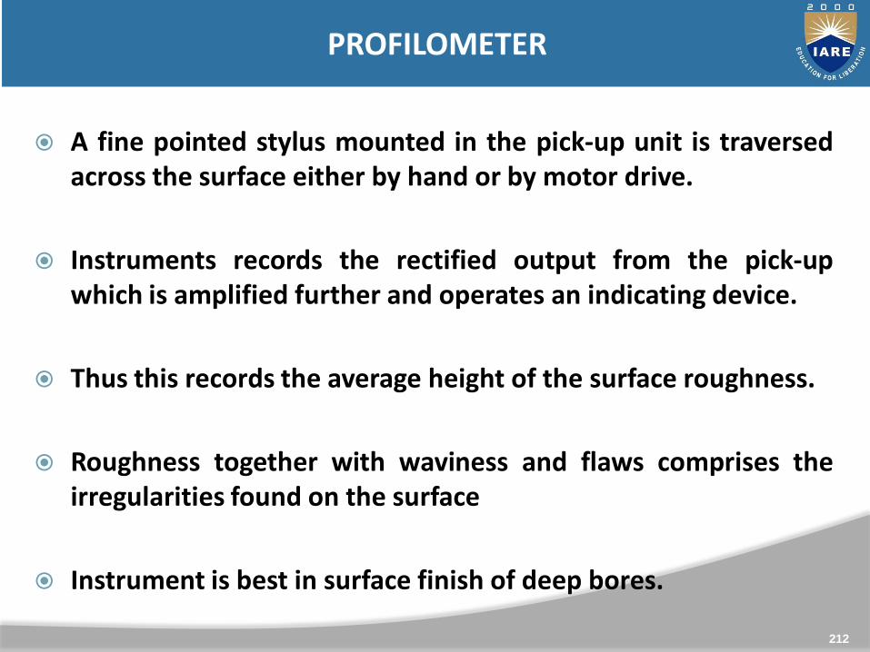
PROFILOMETER
A fine pointed stylus mounted in the pick-up unit is traversedacross the surface either by hand or by motor drive.
Instruments records the rectified output from the pick-upwhich is amplified further and operates an indicating device.
Thus this records the average height of the surface roughness.
Roughness together with waviness and flaws comprises theirregularities found on the surface
Instrument is best in surface finish of deep bores.
213
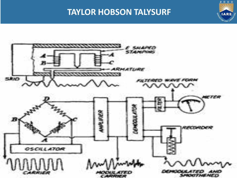
TAYLOR HOBSON TALYSURF
214
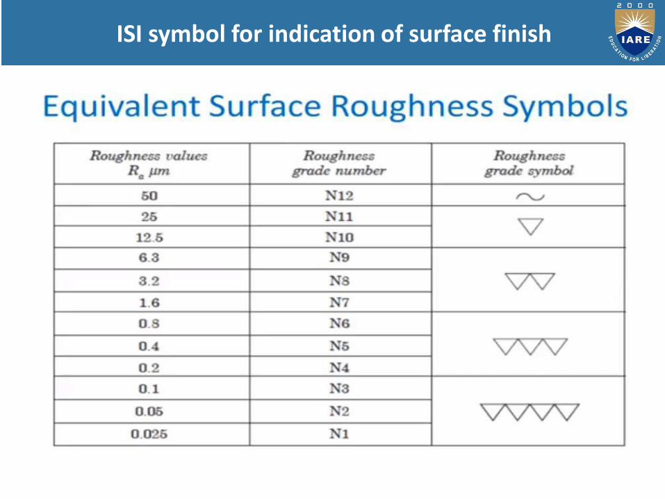
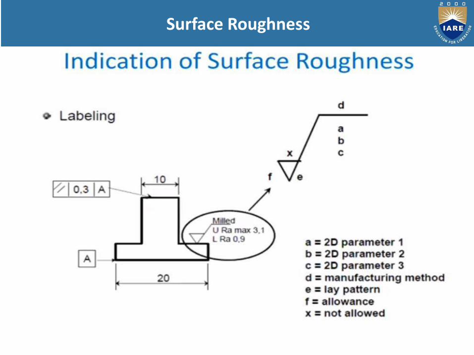
ISI symbol for indication of surface finish
215
216
Surface Roughness
217

218
219
220
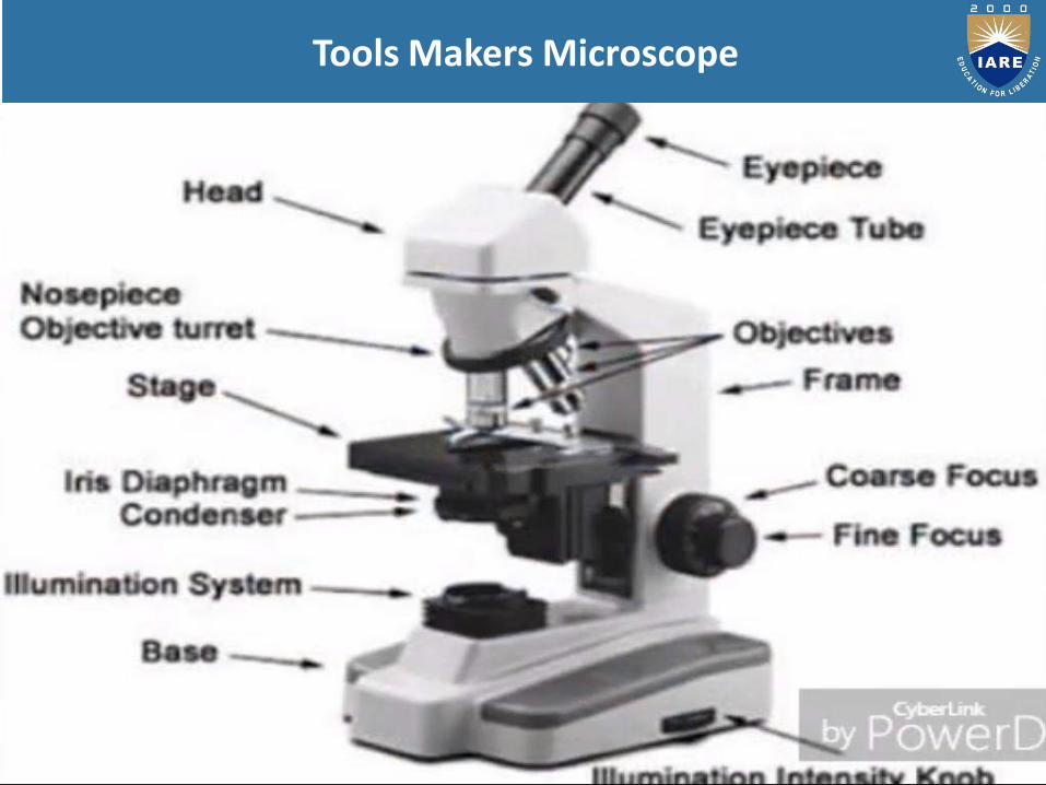
Tools Makers Microscope
221
222
223
224

225
226
227
228
229

230
231
232

233
234
235
236
Collimator
An optical device that generates a parallel beam of light.Often used to compensate for laser beam divergence.
A similar device that produces a parallel beam ofparticles such as neutrons.
A small telescope attached to a larger one, used to pointit in the correct general direction.
It is an optical angular measuring instruments
Used for non contact measurement of small angleswith very high sensitivity
It has high accuracy
237
Autocollimator
238
239
240
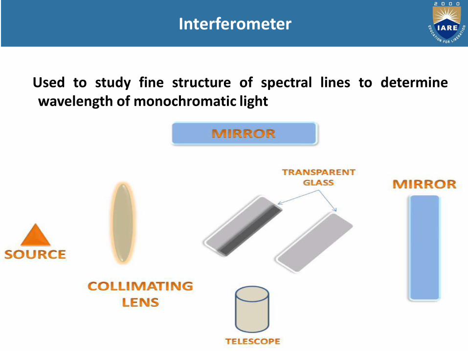
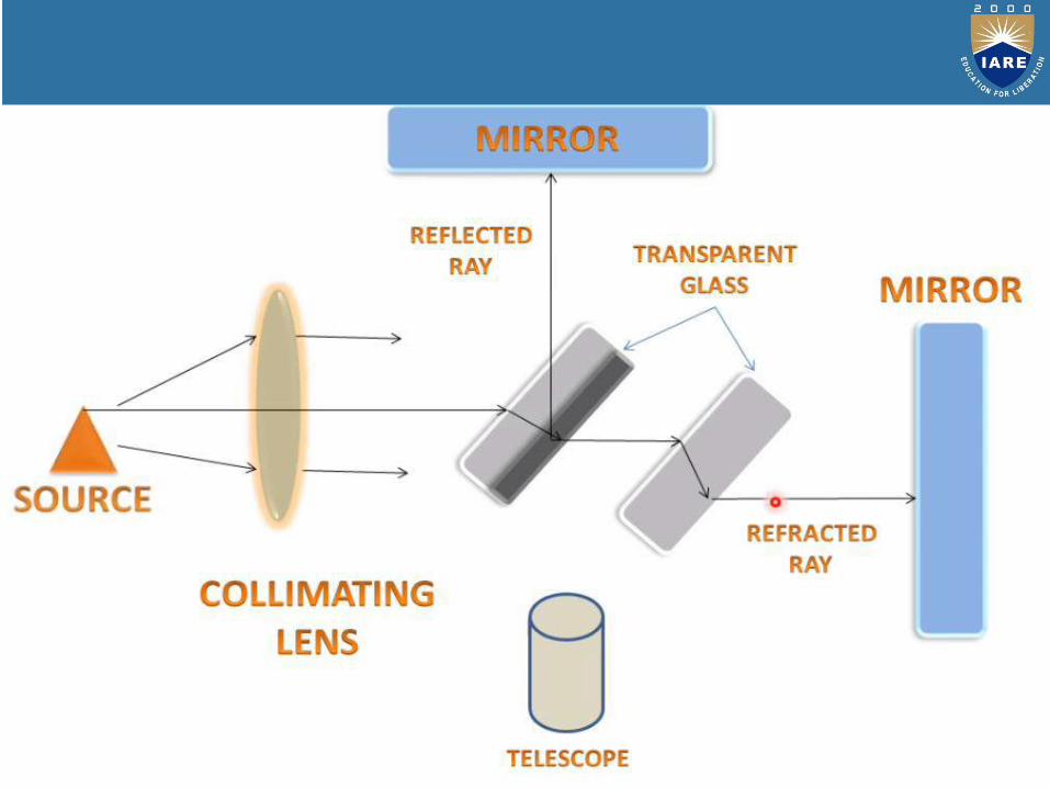
Used to study fine structure of spectral lines to determinewavelength of monochromatic light
241
Interferometer
242
243
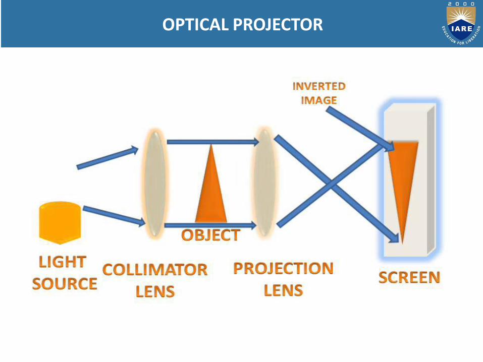
OPTICAL PROJECTOR

244