Embed Size (px)
Citation preview
30380-EN_Ver2.3.fm/2 Schneider Electric
1
1
2
Electromechanical pressure switches 4
For power circuits, types FTG, FSG and FYG
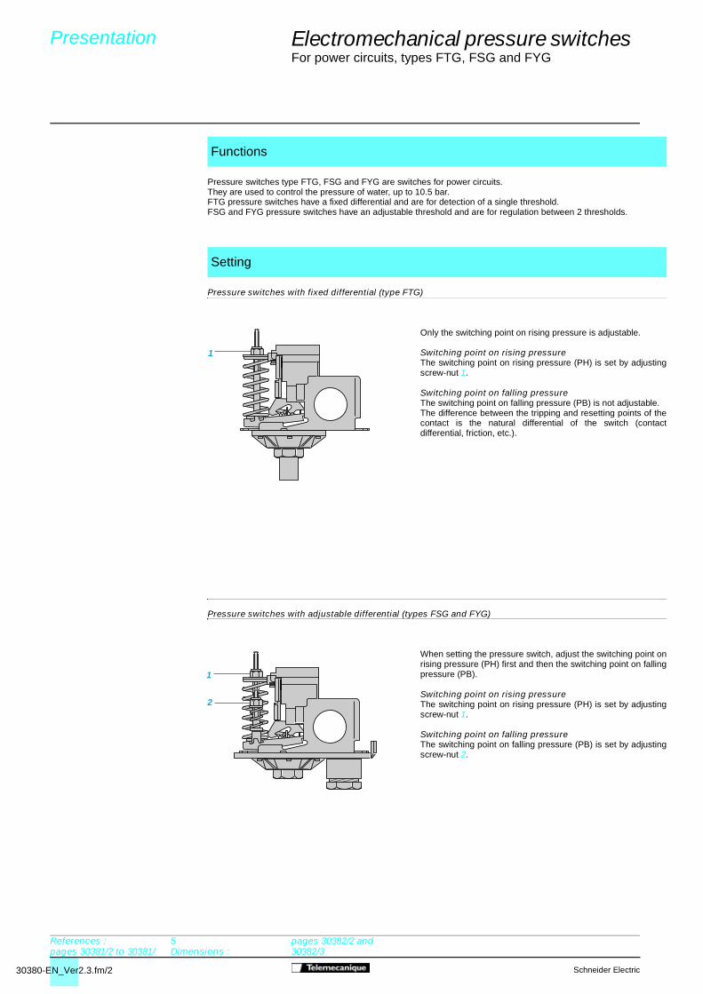
Pressure switches type FTG, FSG and FYG are switches for power circuits.They are used to control the pressure of water, up to 10.5 bar.FTG pressure switches have a fixed differential and are for detection of a single threshold. FSG and FYG pressure switches have an adjustable threshold and are for regulation between 2 thresholds.
Pressure switches with fixed differential (type FTG)
Only the switching point on rising pressure is adjustable.
Switching point on rising pressureThe switching point on rising pressure (PH) is set by adjustingscrew-nut 1.
Switching point on falling pressureThe switching point on falling pressure (PB) is not adjustable. The difference between the tripping and resetting points of thecontact is the natural differential of the switch (contactdifferential, friction, etc.).
Pressure switches with adjustable differential (types FSG and FYG)
When setting the pressure switch, adjust the switching point onrising pressure (PH) first and then the switching point on fallingpressure (PB).
Switching point on rising pressureThe switching point on rising pressure (PH) is set by adjustingscrew-nut 1.
Switching point on falling pressureThe switching point on falling pressure (PB) is set by adjustingscrew-nut 2.
Functions
Setting
Presentation 0
References : pages 30381/2 to 30381/
5Dimensions :
pages 30382/2 and 30382/3

30380-EN_Ver2.3.fm/3Schneider Electric
Electromechanical pressure switches 4
For power circuits, types FTG, FSG and FYG
Type FTG-p FSG-p and FYG-p2 FSG-2NE
Environment characteristics
Conforming to standards e, IEC/EN 60730
Protective treatment Standard version : “TC”
Ambient air temperature °C For operation : 0…+ 45. For storage : - 30…+ 80
Fluids controlled Fresh water, sea water (0…+ 70 °C)
Materials Case: polystyrene, resistant to mechanical impactComponent materials in contact with fluid : nylon 6/6, zinc plated steel, nitrile
Operating position All positions
Electric shock protection Class I conforming to IEC 536
Degree of protection IP 20 conforming to IEC/EN 60529 IP 65 conforming to IEC/EN 60529
Operating rate Operating 600cycl./hour.
Repeat accuracy < 2 %
Fluid connections FpG-2, FYG-p2 : G 1/4 (BSP female) conforming to NF E 03-005, ISO 228 FpG-9 : R 1/4 (BSP male) conforming to NF E 03-004, ISO 7
Electrical connections Terminals. 2 cable entries with wire holder Terminals. 2 entries incorporating n° 13 (DIN Pg 13.5) cable gland
Contact block characteristics
Rated operational characteristics Ie = 10 A, Ue = a 250 V conforming to EN 60730-1
Power ratings of a 2-pole a 2-pole a 2-pole a 2-pole a 2-pole a 2-polecontrolled motors Voltage single-phase 3-phase single-phase 3-phase single-phase 3-phase
110 V 0.75 kW (1 HP) 1.1 kW (1.5 HP) 0.75 kW (1 HP) 1.1 kW (1.5 HP) 0.75 kW (1 HP) 1.1 kW (1.5 HP)
230 V 1.1 kW (1.5 HP) 1.5 kW (2 HP) 1.5 kW (2 HP) 2.2 kW (3 HP) 1.5 kW (2 HP) 2.2 kW (3 HP)
400 V 1.5 kW (2 HP) 1.5 kW (2 HP) 1.5 kW (2 HP) 2.2 kW (3 HP) 1.5 kW (2 HP) 2.2 kW (3 HP)
Rated insulation voltage V Ui = 500 conforming to IEC/EN 60947-1
Rated impulse withstand voltage kV U imp = 6 conforming to IEC/EN 60947-1
Contact operation One 2-pole 2 N/C (4 terminal) contact, snap action
Short-circuit protection 20 A cartridge fuse type gG
Cabling Screw clamp terminals. Clamping capacity, min. : 1 x 1 mm2, min. : 2 x 2 mm2
Electrical durability Op. 40,000 at an operating rate of 100,000 at an operating rate of 600 operating cycles/hourcycles 600 operating cycles/hour
Characteristics 0
References :pages 30381/2 to 30381/5
Dimensions : pages 30382/2 and
30382/3

30381-EN_Ver2.3.fm/2 Schneider Electric
bar
bar
0
4
3
2
1
5
3,1210 4 5
4,6
1,4
0,3
PH
PB
34
12
References,characteristics 0
Electromechanical pressure switches 4
For power circuits, type FTGSize 4.6 bar (66.7 psi).Fixed differential, for detection of a single thresholdSwitches with 2-pole 2 N/C contact Degree of protection IP 20
(1) Component materials of sensor in contact with the fluid, see page 30380/3.
Fluid connection G 1/4 (BSP female) R 1/4 (BSP male)
Adjustable range of switching 1.4…4.6 bar (20.3…66.7 psi)point (PH) (Rising pressure)
References
Fluids controlled: fresh water,sea water, from 0 °C to + 70 °C (1) FTG-2 FTG-9
Weight (kg) 0.340 0.340
Complementary characteristics not shown under general characteristics (page 30380/3)
Natural At low setting 1.1 bar (15.95 psi)differential(subtract from At middle setting 1.3 bar (18.85 psi)PH to give PB)
At high setting 1.5 bar (21.75 psi)
Maximum Per cycle 5.75 bar (83.38 psi)permissiblepressure Accidental 8 bar (116 psi)
Destruction pressure 20 bar (290 psi)
Mechanical durability 4 x 10⁵ operating cycles
Cable entry 2 entries with wire holder
Pressure switch type DiaphragmOperating curves Connections
Falling pressure
Ris
ing
pres
sure
Dimensions :page 30382/2
Time
Adjustable value– – – – Non adjustable value
Pressure

30381-EN_Ver2.3.fm/3Schneider Electric
bar
bar
0
4
3
2
1
5
3,4210 4 5
4,6
1,4
0,3 3
12
2,3
PH
PB
34
12
References,characteristics (continued) 0
Electromechanical pressure switches 4
For power circuits, type FSGSize 4.6 bar (66.7 psi).Adjustable differential, for regulation between 2 thresholdsSwitches with 2-pole 2 N/C contact Degree of protection IP 20
(1) Component materials of sensor in contact with the fluid, see page 30380/3.
Fluid connection G 1/4 (BSP female) R 1/4 (BSP male)
Adjustable range of switching 1.4…4.6 bar (20.3…66.7 psi)point (PH) (Rising pressure)
References
Fluids controlled: fresh water,sea water, from 0 °C to + 70 °C (1) FSG-2 FSG-9
Weight (kg) 0.340 0.340
Complementary characteristics not shown under general characteristics (page 30380/3)
Possible Max. at low setting 2.1 bar (30.45 psi)differential(subtract Max. at middle setting 2.2 bar (31.9 psi)from PHto give PB) Max. at high setting 2.3 bar (33.35 psi)
Min. at low setting 1 bar (14.5 psi)
Min. at middle setting 1.1 bar (15.95 psi)
Min. at high setting 1.2 bar (17.4 psi)
Maximum Per cycle 5.75 bar 83.38 psi)permissiblepressure Accidental 8 bar (116 psi)
Destruction pressure 20 bar (290 psi)
Mechanical durability 1 x 10⁶ operating cycles
Cable entry 2 entries with wire holder
Pressure switch type DiaphragmOperating curves Connections
Falling pressure
Ris
ing
pres
sure
Dimensions :page 30382/2
1 Maximum differential2 Minimum differential
Time
Adjustable value
Pressure

30381-EN_Ver2.3.fm/4 Schneider Electric
bar
bar
0
4
3
2
1
5
3,4210 4 5
4,6
1,4
0,3 3
12
2,3
PH
PB
34
12
References,characteristics (continued) 0
Electromechanical pressure switches 4
For power circuits, type FSG-2NESize 4.6 bar (66.7 psi).Adjustable differential, for regulation between 2 thresholdsSwitches with 2-pole 2 N/C contact Degree of protection IP 65
(1) Component materials of sensor in contact with the fluid, see page 30380/3.
Fluid connection G 1/4 (BSP female)
Adjustable range of switching 1.4…4.6 bar (20.3…66.7 psi)point (PH) (Rising pressure)
References
Fluids controlled: fresh water,sea water, from 0 °C to + 70 °C (1) FSG-2NE
Weight (kg) 0.360
Complementary characteristics not shown under general characteristics (page 30380/3)
Possible Max. at low setting 2.1 bar (30.45 psi)differential(subtract Max. at middle setting 2.2 bar (31.9 psi)from PHto give PB) Max. at high setting 2.3 bar (33.35 psi)
Min. at low setting 1 bar (14.5 psi)
Min. at middle setting 1.1 bar (15.95 psi)
Min. at high setting 1.2 bar (17.4 psi)
Maximum Per cycle 5.75 bar (83.38 psi)permissiblepressure Occasional surge 8 bar (116 psi)
Destruction pressure 20 bar (290 psi)
Mechanical durability 1 x 10⁶ operating cycles
Cable entry 2 entries incorporating n° 13 plastic cable gland conforming to NF C 68-300 (DIN Pg 13.5). Clamping capacity : Ø 9 to 13 mm
Pressure switch type DiaphragmOperating curves Connections
Falling pressure
Ris
ing
pres
sure
Dimensions :page 30382/3
1 Maximum differential2 Minimum differential
Time
Adjustable value
Pressure

30381-EN_Ver2.3.fm/5Schneider Electric
bar
bar
0
4
3
2
1
5
2,610 4 5
10
1
2
6 7,1 8,2 9 10
5,6
7
8
9
bar
bar
0
4
2,8
2
1
5
210 83
1 2
5,4 6 7
6
7
8
0,5 4,3
PH
PB
34
12
References,characteristics (continued) 0
1 Maximum differential2 Minimum differential
Time
Adjustable value
Pressure
1 Maximum differential2 Minimum differential
Ris
ing
pres
sure
Falling pressure Falling pressure
Ris
ing
pres
sure
Dimensions :page 30382/3
Electromechanical pressure switches 4
For power circuits, type FYGSizes 7 and 10.5 bar (101.5 and 152.3 psi). Adjustable differential, for regulation between 2 thresholds Switches with 2-pole 2 N/C contact.Degree of protection IP 20
(1) Component materials of sensor in contact with the fluid, see page 30380/3.
Fluid connection G 1/4 (BSP female)
Adjustable range of switching 2.8…7 bar (40.6…101.5 psi) 5.6…10.5 bar (81.2…152.3 psi)point (PH) (Rising pressure)
References
Fluids controlled: fresh water,sea water, from 0 °C to + 70 °C (1) FYG-22 FYG-32
Weight (kg) 0.340 0.340
Complementary characteristics not shown under general characteristics (page 30380/3)
Possible Max. at low setting 2.3 bar (33.35 psi) 3 bar (43.5 psi)differential(subtract Max. at middle setting 2.5 bar (36.25 psi) 3.2 bar (46.4 psi)from PHto give PB) Max. at high setting 2.7 bar (39.15 psi) 3.4 bar (49.3 psi)
Min. at low setting 1.2 bar (17.4 psi) 1.9 bar (27.55 psi)
Min. at middle setting 1.4 bar (20.3 psi) 2.1 bar (30.45 psi)
Min. at high setting 1.6 bar (23.2 psi) 2.3 bar (33.35 psi)
Maximum Per cycle 8.75 bar (126.9 psi) 13 bar (188.5 psi)permissiblepressure Occasional surge 15 bar (217.5 psi) 15 bar (217.5 psi)
Destruction pressure 20 bar (290 psi) 20 bar (290 psi)
Mechanical durability 1 x 10⁶ operating cycles
Cable entry 2 entries with wire holder
Pressure switch type DiaphragmOperating curves ConnectionsFYG-22 FYG-32
30382-EN_Ver2.3.fm/2 Schneider Electric
R 1/4
72
105
32
102
22
60
31
Ø22
R 1/4
72
105
32
102
22
60
31
Ø22
72
96
23
22
102
Ø22
60
31 G 1/4
72
96
23
22
102
Ø22
60
31 G 1/4
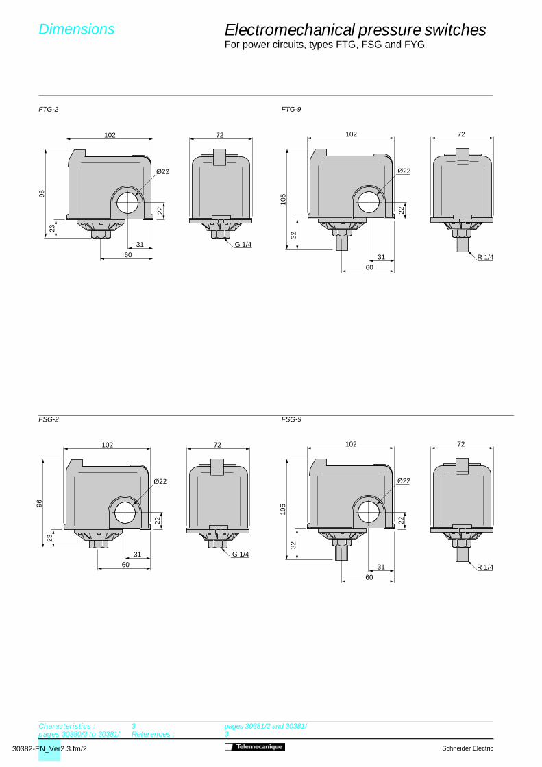
Electromechanical pressure switches 4
For power circuits, types FTG, FSG and FYG
FTG-2 FTG-9
FSG-2 FSG-9
Dimensions 0
Characteristics :pages 30380/3 to 30381/
3References :
pages 30381/2 and 30381/3

30382-EN_Ver2.3.fm/3Schneider Electric
115
41
106
25
72
63G 1/4
72
22
94
21
102
60
31
Ø22
G 1/4
Electromechanical pressure switches 4
For power circuits, types FTG, FSG and FYG
FSG-2NE
FYG-22, FYG-32
Dimensions (continued) 0
Characteristics :pages 30380/3, 30381/4
and 30381/5References :
pages 30381/4 and 30381/5

30395-EN_Ver2.3.fm/2 Schneider Electric
1
2
Electromechanical pressure switches 4
For power circuits, type XMP
Pressure switches type XMP are switches for power circuits (direct switching), with an adjustable differential.They are used to control the pressure of water and air, up to 25 bar.
Case
Pressure switches type XMP, depending on the model, include:
3 types case:- bare case,- case with On/Off knob (black) : used as a switch for starting and stopping the installation,- case with reset knob (yellow) : necessary when the safety requirements of the system include tripping in the eventof overpressure. Resetting is not automatic on return to normal pressure, and it can only be achieved by manuallyturning the “Reset” knob.
and 2 levels of sealing :- IP 54,- IP 65.
Decompression valve
Depending on the model, 2 types of decompression valve can be fitted to XMP pressure switches.- straight, instant connection, decompression valve (connection by Ø 6 mm plastic tube),- straight, olive connection, decompression valve (connection by Ø 6 mm plastic or metal tube).
When setting XMP pressure switches, adjust the switching point on risingpressure (PH) first and then the switching point on falling pressure (PB).
Switching point on rising pressureThe switching point on rising pressure (PH) is set by adjusting the screw-nut orknurled knob 1.Tighten either the nut or knurled knob 1 to increase the high point switchingvalue.
Switching point on falling pressureThe switching point on falling pressure is set by adjusting screw-nut 2.Tighten nut 2 to reduce the low point switching value (increase in differential).
Function
Equipment fitted to various models
Setting
Presentation 0
References :pages 30396/2 to 30396/
9Dimensions :
page 30399/3

30395-EN_Ver2.3.fm/3Schneider Electric
Electromechanical pressure switches 4
For power circuits, type XMP
Environment characteristics
Conforming to standards e, IEC/EN 60947-4-1, UL 508, CSA C 22-2 n° 14
Product certifications Special version : CSA, UL
Protective treatment Standard version : “TC”. Special version : “TH”
Ambient air temperature °C Operation : - 25…+ 70. Storage : - 40…+ 70
Fluids controlled Air, fresh water, sea water (0…+ 70 °C)
Materials Case : polyamide impregnated with fibre glassComponent materials in contact with fluid : chromated zinc alloy (fluid entry), canvas covered nitrile (diaphragm)
Operating position All positions
Vibration resistance 3 gn (10…500 Hz) conforming to IEC 68-2-6
Shock resistance 50 gn conforming to IEC 68-2-27
Electric shock protection Class I conforming to IEC 536
Degree of protection IP 54, conforming to IEC/EN 60529 or IP 65 for universal model
Operating rate Operating � 600 cycl./hour.
Repeat accuracy < 3.5 %
Fluid connections G 1/4, 4 x G 1/4 or G 3/8 (BSP female) conforming to NF E 03-005, ISO 228
Electrical connections 2 tapped entries for n° 13 cable gland (DIN Pg 13.5)
Contact block characteristics
Rated insulation voltage V Ui = 500 conforming to IEC/EN 60947-1
Rated impulse withstand voltage V U imp = 6 kV conforming to IEC/EN 60 947-1
Contact operation One 2-pole 2 N/C or one 3-pole 3 N/C contact, snap action
Resistance across terminals m� � 25 conforming to NF C 93-050 method A or IEC 255-7 category 3
Terminal referencing Conforming to CENELEC EN 50013
Short-circuit protection Cartridge fuse type Am
Cabling Screw clamp terminals. Minimum clamping capacity : 2 x 4 mm2
Electrical durability Power Number of operating cyclesOperating rate : 600 operating cyclesper hour kW a 400 V, 3-phase a 230 V, 3-phaseLoad factor : 0.4
1.5 1,000,000 600,000
2.2 700,000 –
3 500,000 –
Characteristics 0
References :pages 30396/2 to 30396/9
Dimensions :page 30399/3

30396-EN_Ver2.3.fm/2 Schneider Electric
PH
PB
1 2 3
3
0
4
5
6
1
2
4 60,2 1,8 4,8
21
bar
bar
Falling pressure
Electromechanical pressure switches 4
Type XMP, IP 54Size 6 bar (87 psi)Adjustable differential, for regulation between 2 thresholdsSwitches with 2-pole 2 N/C or 3-pole 3 N/C contact
Switches without decompression valve
Switches with straight decompression valve, instant connection
Fluid connection G 1/4 (BSP female)
Adjustable range of switchingpoint (PH) (Rising pressure) 1…6 bar (14.5…87 psi)
Type of contact 2-pole 2 N/C 3-pole 3 N/C
References (1)
Bare case 1 XMP-A06B2131 XMP-A06C2131
Case with reset knob 2 XMP-B06B2131 –
Case with On/Off knob 2 XMP-C06B2131 XMP-C06C2131
Weight (kg) 0.430 0.430
Bare case 1 XMP-D06B2131 XMP-D06C2131
Case with On/Off knob 2 XMP-E06B2131 XMP-E06C2131
Weight (kg) 0.450 0.450
Complementary characteristics not shown under general characteristics (page 30395/3)
Possible Min. at low setting 0.8 bar (11.6 psi)differential(subtract from Min. at high setting 1.2 bar (17.4 psi)PH to give PB)
Max. at high setting 4.2 bar (60.9 psi)
Destruction pressure 30 bar (435 psi)
Mechanical durability 1 million operating cycles
Cable entry 2 entries tapped for n° 13 cable gland, conforming to NF C 68-300 (DIN Pg 13.5)
Pressure switch type DiaphragmOperating curves
References,characteristics 0
Accessories :page 30399/2
Dimensions :page 30399/3
Time
Adjustable value
1 Maximum differential2 Minimum differential
Ris
ing
pres
sure
1 2
Pressure
30396-EN_Ver2.3.fm/3Schneider Electric
34
12
56
34
12
4
(1) References for individually packaged switches. Also available packaged in lots of 10, to order : add the suffix C to the reference selected from above.Example : reference for lot of 10 XMP-A06B2131 pressure switches in one package becomes XMP-A06B2131C.
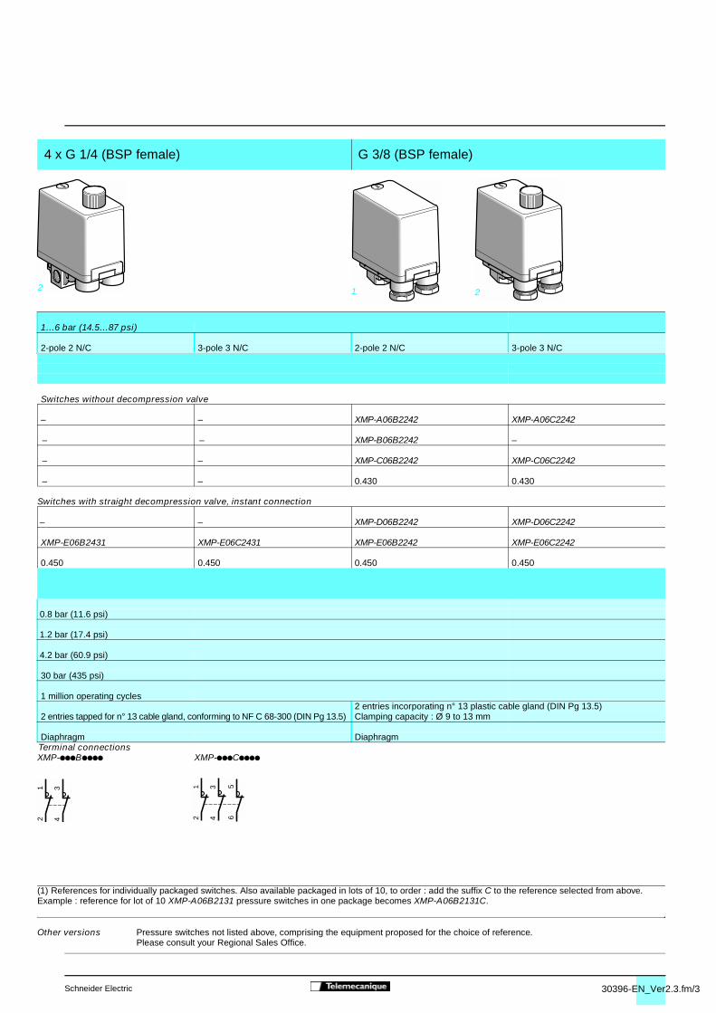
4 x G 1/4 (BSP female) G 3/8 (BSP female)
1…6 bar (14.5…87 psi)
2-pole 2 N/C 3-pole 3 N/C 2-pole 2 N/C 3-pole 3 N/C
Switches without decompression valve
– – XMP-A06B2242 XMP-A06C2242
– – XMP-B06B2242 –
– – XMP-C06B2242 XMP-C06C2242
– – 0.430 0.430
Switches with straight decompression valve, instant connection
– – XMP-D06B2242 XMP-D06C2242
XMP-E06B2431 XMP-E06C2431 XMP-E06B2242 XMP-E06C2242
0.450 0.450 0.450 0.450
0.8 bar (11.6 psi)
1.2 bar (17.4 psi)
4.2 bar (60.9 psi)
30 bar (435 psi)
1 million operating cycles2 entries incorporating n° 13 plastic cable gland (DIN Pg 13.5)
2 entries tapped for n° 13 cable gland, conforming to NF C 68-300 (DIN Pg 13.5) Clamping capacity : Ø 9 to 13 mm
Diaphragm DiaphragmTerminal connectionsXMP-pppBpppp XMP-pppCpppp
Other versions Pressure switches not listed above, comprising the equipment proposed for the choice of reference.Please consult your Regional Sales Office.
0
2 1 2

30396-EN_Ver2.3.fm/4 Schneider Electric
PH
PB
bar2 4 6
6
0
8
10
12
2
4
8 100,3 3,6 10,3
2
1
1,3
bar
Electromechanical pressure switches 4
Type XMP, IP 54Size 12 bar (174 psi)Adjustable differential, for regulation between 2 thresholdsSwitches with 2-pole 2 N/C or 3-pole 3 N/C contact
Switches without decompression valve
Switches with straight decompression valve, instant connection
Switches with straight decompression valve, olive connection
Fluid connection G 1/4 (BSP female)
Adjustable range of switchingpoint (PH) (Rising pressure) 1.3…12 bar (18.85…174 psi)
Type of contact 2-pole 2 N/C 3-pole 3 N/C
References (1)
Bare case 1 XMP-A12B2131 XMP-A12C2131
Case with reset knob 2 XMP-B12B2131 –
Case with On/Off knob 2 XMP-C12B2131 XMP-C12C2131Weight (kg) 0.430 0.430
Bare case 1 XMP-D12B2131 XMP-D12C2131
Case with On/Off knob 2 XMP-E12B2131 XMP-E12C2131Weight (kg) 0.450 0.450
Case with On/Off knob 2 XMP-R12B2131 XMP-R12C2131Weight (kg) 0.450 0.450
Complementary characteristics not shown under general characteristics (page 30395/3)
Possible Min. at low setting 1 bar (14.5 psi)differential(subtract from Min. at high setting 1.7 bar (24.6 psi)PH to give PB)
Max. at high setting 8.4 bar (121.8 psi)
Destruction pressure 30 bar (435 psi)
Mechanical durability 1 million operating cycles
Cable entry 2 entries tapped for n° 13 cable gland, conforming to NF C 68-300 (DIN Pg 13.5)
Pressure switch type DiaphragmOperating curves
References,characteristics (continued) 0
Accessories :page 30399/2
Dimensions :page 30399/3
1 2
Pressure
Adjustable value
Time1 Maximum differential2 Minimum differential
Falling pressure
Ris
ing
pres
sure

30396-EN_Ver2.3.fm/5Schneider Electric
34
12
56
34
12
4
Switches with straight decompression valve, olive connection
(1) References for individually packaged switches. Also available packaged in lots of 10, to order : add the suffix C to the reference selected from above.Example : reference for lot of 10 XMP-A12B2131 pressure switches in one package becomes XMP-A12B2131C.
4 x G 1/4 (BSP female) G 3/8 (BSP female)
1.3…12 bar (18.85…174 psi)
2-pole 2 N/C 3-pole 3 N/C 2-pole 2 N/C 3-pole 3 N/C
Switches without decompression valve
– – XMP-A12B2242 XMP-A12C2242
– – XMP-B12B2242 –
– – XMP-C12B2242 XMP-C12C2242– – 0.430 0.430
Switches with straight decompression valve, instant connection
– – XMP-D12B2242 XMP-D12C2242
XMP-E12B2431 XMP-E12C2431 XMP-C12B2242 XMP-C12C22420.450 0.450 0.450 0.450
– – – –– – – –
1 bar (14.5 psi)
1.7 bar (24.6 psi)
8.4 bar (121.8 psi)
30 bar (435 psi)
1 million operating cycles2 entries incorporating n° 13 plastic cable gland (DIN Pg 13.5)
2 entries tapped for n° 13 cable gland, conforming to NF C 68-300 (DIN Pg 13.5) Clamping capacity : Ø 9 to 13 mm
Diaphragm DiaphragmTerminal connectionsXMP-pppBpppp XMP-pppCpppp
Other versions Pressure switches not listed above, comprising the equipment proposed for the choice of reference. Please consult your Regional Sales Office.
0
2 1 2

30396-EN_Ver2.3.fm/6 Schneider Electric
PH
PB
5 10 15
15
0
20
25
30
10
25 300,1 20,5
1
3,5
bar
bar
2
Ris
ing
pres
sure
Electromechanical pressure switches 4
Type XMP, IP 54Size 25 bar (362.5 psi)Adjustable differential, for regulation between 2 thresholdsSwitches with 2-pole 2 N/C or 3-pole 3 N/C contact
Switches without decompression valve
Switches with straight decompression valve, olive connection
Fluid connection G 1/4 (BSP female)
Adjustable range of switchingpoint (PH) (Rising pressure) 3.5…25 bar (50.75…362.5 psi)
Type of contact 2-pole 2 N/C
References (1)
Bare case 1 XMP-A25B2131
Case with reset knob 2 XMP-B25B2131
Case with On/Off knob 2 XMP-C25B2131
Weight (kg) 0.650
Case with On/Off knob 2 XMP-R25B2131
Weight (kg) 0.670
Complementary characteristics not shown under general characteristics (page 30395/3)
Possible Min. at low setting 3.4 bar (49.3 psi)differential(subtract from Min. at high setting 4.5 bar (65.2 psi)PH to give PB)
Max. at high setting 20 bar (290 psi)
Destruction pressure 100 bar (1450 psi)
Mechanical durability 1 million operating cycles
Cable entry 2 entries tapped for n° 13 cable gland, conforming to NF C 68-300 (DIN Pg 13.5)
Pressure switch type DiaphragmOperating curves
References,characteristics (continued) 0
Accessories :page 30399/2
Dimensions :page 30399/3
1 2
1 Maximum differential2 Minimum differential
Adjustable value
Time
Pressure
Falling pressure

30396-EN_Ver2.3.fm/7Schneider Electric
34
12
56
34
12
1 2
4
(1) References for individually packaged switches. Also available packaged in lots of 10, to order : add the suffix C to the reference selected from above.Example : reference for lot of 10 XMP-A25B2131 pressure switches in one package becomes XMP-A25B2131C.
G 1/4 (BSP female)
3.5…25 bar (50.75…362.5 psi)
3-pole 3 N/C
Switches without decompression valve
XMP-A25C2131
–
XMP-C25C2131
0.650
Switches with straight decompression valve, olive connection
XMP-R25C2131
0.670
3.4 bar (49.3 psi)
4.5 bar (65.2 psi)
20 bar (290 psi)
100 bar (1450 psi)
1 million operating cycles
2 entries tapped for n° 13 cable gland, conforming to NF C 68-300 (DIN Pg 13.5)
DiaphragmTerminal connectionsXMP-pppBpppp XMP-pppCpppp
Other versions Pressure switches not listed above, comprising the equipment proposed for the choice of reference. Please consult your Regional Sales Office.
0

30396-EN_Ver2.3.fm/8 Schneider Electric
PH
PB
5 10 15
15
0
20
25
30
10
25 300,1 20,5
1
3,5
bar
bar
2
1 2 3
3
0
4
5
6
1
2
4 60,2 1,8 4,8
21
bar
bar
bar2 4 6
6
0
8
10
12
2
4
8 100,3 3,6 10,3
2
1
1,3
bar
Falling pressure
Electromechanical pressure switches 4
Type XMP, IP 65Sizes 6 to 25 bar (87 to 362.5 psi)Adjustable differential, for regulation between 2 thresholdsSwitches with 2-pole 2 N/C or 3-pole 3 N/C contact
Switches with straight decompression valve, olive connection
Fluid connection G 1/4 (BSP female)
Adjustable range of switchingpoint (PH) (Rising pressure) 1…6 bar (14.5…87 psi) 1.3…12 bar (18.85…174 psi) 3.5…25 bar (50.75…362.5 psi)
Type of contact 2-pole 2 N/C 3-pole 3 N/C 2-pole 2 N/C 3-pole 3 N/C 2-pole 2 N/C 3-pole 3 N/C
References (1)
Case with On/Off knob XMP-R06B2133 XMP-R06C2133 XMP-R12B2133 XMP-R12C2133 XMP-R25B2133 XMP-R25C2133
Weight (kg) 0.450 0.450 0.450 0.450 0.670 0.670
Complementary characteristics not shown under general characteristics (page 30395/3)
Possible Min. at low setting 0.8 bar (11.6 psi) 1 bar (14.5 psi) 3.4 bar (49.3 psi)differential(subtract from Min. at high setting 1.2 bar (17.4 psi) 1.7 bar (24.6 psi) 4.5 bar (65.2 psi)PH to give PB)
Max. at high setting 4.2 bar (60.9 psi) 8.4 bar (121.8 psi) 20 bar (290 psi)
Destruction pressure 30 bar (435 psi) 30 bar (435 psi) 100 bar (1450 psi)
Mechanical durability 1 million operating cycles
Cable entry 2 entries tapped for n° 13 cable gland, conforming to NF C 68-300 (DIN Pg 13.5)
Adjustment of high setting point (PH) By screw-nut
Pressure switch type DiaphragmOperating curvesXMP-R06ppppp XMP-R12ppppp XMP-R25ppppp
References,characteristics (continued) 0
Falling pressure
1 Maximum differential2 Minimum differential
Falling pressure
1 Maximum differential2 Minimum differential
1 Maximum differential2 Minimum differential
Adjustable value
Time
Pressure
Accessories :page 30399/2
Dimensions :page 30399/3
Ris
ing
pres
sure
Ris
ing
pres
sure
Ris
ing
pres
sure
30396-EN_Ver2.3.fm/9Schneider Electric
34
12
56
34
12
4
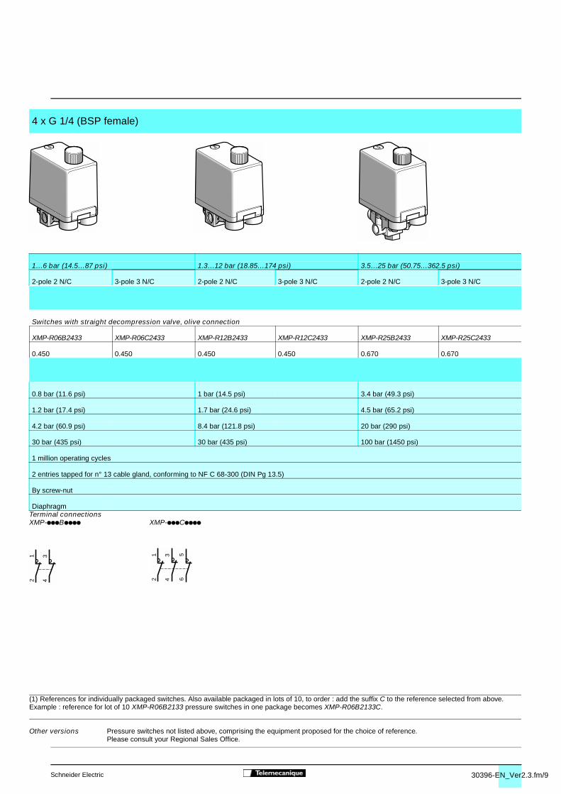
(1) References for individually packaged switches. Also available packaged in lots of 10, to order : add the suffix C to the reference selected from above.Example : reference for lot of 10 XMP-R06B2133 pressure switches in one package becomes XMP-R06B2133C.
4 x G 1/4 (BSP female)
1…6 bar (14.5…87 psi) 1.3…12 bar (18.85…174 psi) 3.5…25 bar (50.75…362.5 psi)
2-pole 2 N/C 3-pole 3 N/C 2-pole 2 N/C 3-pole 3 N/C 2-pole 2 N/C 3-pole 3 N/C
Switches with straight decompression valve, olive connection
XMP-R06B2433 XMP-R06C2433 XMP-R12B2433 XMP-R12C2433 XMP-R25B2433 XMP-R25C2433
0.450 0.450 0.450 0.450 0.670 0.670
0.8 bar (11.6 psi) 1 bar (14.5 psi) 3.4 bar (49.3 psi)
1.2 bar (17.4 psi) 1.7 bar (24.6 psi) 4.5 bar (65.2 psi)
4.2 bar (60.9 psi) 8.4 bar (121.8 psi) 20 bar (290 psi)
30 bar (435 psi) 30 bar (435 psi) 100 bar (1450 psi)
1 million operating cycles
2 entries tapped for n° 13 cable gland, conforming to NF C 68-300 (DIN Pg 13.5)
By screw-nut
DiaphragmTerminal connectionsXMP-pppBpppp XMP-pppCpppp
Other versions Pressure switches not listed above, comprising the equipment proposed for the choice of reference. Please consult your Regional Sales Office.
0

30399-EN_Ver3.3.fm/2 Schneider Electric
Electromechanical pressure switches 4
For power circuits, type XMPAccessories and replacement parts
Description Reference Weightkg
Fixing bracket XMA-ZL001 0.035
Knurled adjustment knob, Ø 36 mm XMP-MDR01 0.010fits over adjustment screws to facilitatesetting
N° 13 plastic cable gland With anti pull-out ring DE9-PM1201 0.005(for cable Ø 6…9 mm)
Without anti pull-out ring DE9-PM1202 0.005(for cable Ø 6…9 mm)
With anti pull-out ring DE9-PM1203 0.005(for cable Ø 9…12.5 mm)
Without anti pull-out ring DE9-PM1204 0.005(for cable Ø 9…12.5 mm)
Description For pressure switch Reference Weightkg
Diaphragms Size 6 bar XMP-Z31 0.005
Size 12 bar XMP-Z32 0.005
Size 25 bar XMP-Z33 0.005
8119
16
XMA-ZL001
8119
20
XMP-MDR01
8119
16
DE9-PM1201
8119
17
DE9-PM1202
8119
19
XMP-Z3p
Dimensions :page 30399/3
References 0

30399-EN_Ver3.3.fm/3Schneider Electric
43,5
58
97,5
(1)
1910
6
30,5
=
57
=
A
r = 63 (2)
43,5
58
97,5
(1)
1910
6
30,5
=
57
=
r = 63 (2)
C
D
B
A
43,5
58
97,5
(1)
1912
6
30,5
=
57
=
AC
D
B
r = 63 (2)
117
22,5
11
119
22,513
22,5
136
18,512,5 38
3,6
54
40 19
24,7
5 52
Electromechanical pressure switches 4
For power circuits, type XMP
XMP-p06ppppp and XMP-p12pppppFluid connection G 1/4 or G 3/8 (BSP female)
XMP-p06ppppp and XMP-p12pppppFluid connection 4 x G 1/4 (BSP female)
XMP-p06ppppp and XMP-p12pppppWith straight, instant connection,
Without decompression valve Without decompression valve decompression valve
With straight, olive connection,decompression valve
ØA = G 1/4 or G 3/8 (BSP female) ØA = ØB = ØC = ØD = G 1/4 (BSP female)(1) 2 tapped entries for n° 13 cable gland (1) 2 tapped entries for n° 13 cable gland(2) Minimum clearance zone for screwing-on (2) Minimum clearance zone for screwing-onpressure switch at point A pressure switch at point AXMP-p25ppppp XMP-p25ppppp Fixing bracketFluid connection G 1/4 or 4 x G 1/4 (BSP female) With straight, olive connection, decompression valve XMA-ZL001Without decompression valve
XMP-p25p21pp : ØA only = G 1/4 (BSP female)XMP-p25p24pp : ØA = ØB = ØC = ØD = G 1/4 (BSP female)(1) 2 tapped entries for n° 13 cable gland (2) Minimum clearance zone for screwing-onpressure switch at point A
Dimensions 0
Characteristics :page 30395/3 to 30396/9
References :pages 30396/2 to 30396/9

30350-EN_Ver4.1.fm/2 Schneider Electric
����������������
�����������
����������
�����������������
������
��������������������
�����������
����������
�����
������
��������������������
���������
������������
����������������������
����������
�������
1
����������������
�����������
���������
�����������������
������
���������������������
����������
����������
�����
������
�������������������
���������
�������������
����������������������
����������
�������
��������������
1 2
�������������������
�����������
���������
�����������������
������
���������������������
����������
����������
�����
�����
�������������������
���������
�����������������
����������������������
����������
�������
��������������
1 2
Electromechanical pressure and vacuum switches 4
Nautilus® For control circuits, type XML
Pressure and vacuum switches type XML are switches for control circuits.They are used to control the pressure of hydraulic oils, fresh water, sea water, air, steam, corrosive fluids or viscousproducts, up to 500 bar.
XML-A pressure and vacuum switches have a fixed differential and are for detection of a single threshold.
XML-B pressure and vacuum switches have an adjustable differential and are for regulation between 2 thresholds.They incorporate a 1 C/O single-pole contact.XML-C pressure and vacuum switches have an adjustable differential and are for regulation between 2 thresholds.They incorporate 2 C/O single-pole contacts.XML-D pressure and vacuum switches are dual stage switches, each stage with a fixed differential, and are fordetection at each threshold.They incorporate 2 C/O single-pole contacts (one per stage).
When setting XML pressure and vacuum switches, adjust the switching point on rising pressure (PH) first and then theswitching point on falling pressure (PB).
Pressure and vacuum switches with fixed differential, type XML-A
Switching point on rising pressureThe switching point on rising pressure (PH) is set by adjusting the red screw 1.
Switching point on falling pressureThe switching point on falling pressure (PB) is not adjustable. The difference between the tripping and resetting points of the contact is thenatural differential of the switch (contact differential, friction, etc.).
Pressure and vacuum switches with adjustable differential, types XML-B and XML-C
Switching point on rising pressureThe switching point on rising pressure (PH) is set by adjusting the red screw 1.
Switching point on falling pressureThe switching point on falling pressure (PB) is set by adjusting the green screw2.
Dual stage pressure and vacuum switches with fixed differential for each threshold, type XML-D
Switching point on rising pressure of stage 1 and stage 2The first stage switching point on rising pressure (PH1) is set by adjusting thered screw 1.The second stage switching point on rising pressure (PH2) is set by adjustingthe blue screw 2.
Switching points on falling pressureThe switching points on falling pressure (PB1 and PB2) are not adjustable. The difference between the tripping and resetting points of each contact isthe natural differential of the switch (contact differential, friction, etc.).
Function
They incorporate a 1 C/O single-pole contact.
Setting
Presentation 0

30350-EN_Ver4.1.fm/3Schneider Electric
0,5 1 2 5 100,1
0,5
1
5
2
34
230 V 48 V
Ithe
12/24 V
3 4
110 V
Mill
ions
of o
pera
ting
cycl
es
Current in A
o Inductive circuit Ithe = 10 A
0,3 0,5 1 2 5 10 200,1
0,2
0,5
1
2
345
7
110 V
48 V
230 V
Ithe
Mill
ions
of o
pera
ting
cycl
es
Current in A
o Inductive circuit Ithe = 10 A
Electromechanical pressure and vacuum switches 4
Nautilus® For control circuits, type XML
Utilisation categories AC-15 and DC-13
Operating rate : 3600 operating cyclesper hourLoad factor : 0.5
Environment characteristics
Conforming to standards e, IEC/EN 60947-5-1, UL 508, CSA C22-2 n° 14
Product certifications UL, CSA
Protective treatment Standard version “TC”. Special version “TH”.
Ambient air temperature °C Operation : - 25…+ 70. Storage : - 40 …+ 70
Fluids or products controlled Hydraulic oils, air, fresh water, sea water (0…+ 160 °C), depending on modelSteam, corrosive fluids, viscous products (0…+ 160 °C), depending on model
Materials Case : zinc alloyComponent materials in contact with fluid : see pages 30369/2 and 30369/3
Operating position All positions
Vibration resistance 4 gn (30 to 500 Hz) to IEC 68-2-6 except XML-pL35ppppp, XML-p001ppppp and XML-BM03ppppp : 2 gn
Shock resistance 50 gn conforming to IEC 68-2-27 except XML-pL35ppppp, XML-p001ppppp and XML-BM03ppppp : 30 gnElectric shock protection Class I conforming to IEC 1140, IEC 536 and NF C 20-030Degree of protection Screw terminal models : IP 66 conforming to IEC/EN 60529
Connector models : IP 65 conforming to IEC/EN 60529
Operating rate Operat. Piston version switches : � 60 (for temperatures > 0 °C)cycl./min Diaphragm version switches : � 120 (for temperatures > 0 °C)
Repeat accuracy < 2 %
Fluid connections G 1/4 (BSP female) conforming to NF E 03-005, ISO 228 or 1/4" NPTF (consult your Regional Sales Office)Electrical connections Screw terminal models : entry tapped for n° 13 (DIN Pg 13.5) cable gland.
For an entry tapped ISO M20 x 1.5, replace the last number of the reference by 2 (example : XMLA010A2S11 becomes XMLA010A2S12).
For an entry tapped 1/2" NPT, please consult your Regional Sales Office.Connector models : either type DIN 43650 A or M12 connector, please consult your Regional Sales Office.
Contact block characteristics
Rated operational characteristics a AC-15 ; B300 (Ue = 240 V, Ie = 1.5 A - Ue = 120 V, Ie = 3 A)c DC-13 ; R300 (Ue = 250 V, Ie = 0.1 A) conforming to IEC 947-5-1 Appendix A, EN 60 947-5-1
Rated insulation voltage Ui = 500 V conforming to IEC/EN 60947-1Ui = 300 V conforming to UL 508, CSA C22-2 n° 14
Rated impulse withstand voltage U imp = 6 kV conforming to IEC/EN 60947-1
Contact operation Silver tipped contactsXML-A and XML-B : 1 C/O single-pole contact (4 terminal), snap action XML-C : 2 C/O single-pole contacts (8 terminal), simultaneous, snap action XML-D : 2 C/O single-pole contacts (8 terminal), staggered, snap action
Resistance across terminals m� < 25 conforming to NF C 93-050 method A or IEC 255-7 category 3Terminal referencing Conforming to CENELEC EN 50013Short-circuit protection 10 A cartridge fuse type gG (gl)Cabling Screw clamp terminals. Clamping capacity, min. : 1 x 0.2 mm2, max. : 2 x 2.5 mm2
Electrical durability XML-A and XML-B XML-C and XML-Dconforming to IEC 947-5-1 Appendix C a.c. supply a 50/60 Hz a.c. supply a 50/60 Hz
d.c. supply c d.c. supply cPower broken in W Power broken in Wfor 1 million operating cycles for 5 million operating cyclesVoltage V 24 48 120 Voltage V 24 48 120o W 31 29 26 o W 10 7 4
Characteristics 0

30351-EN_Ver3.3.fm/2 Schneider Electric
PH
PB
1314 12
11
321
bar
bar 0-0,04-0,2-0,4-0,6-0,76
-0,2
-0,28
-0,4
-0,6
-0,8
-1
-1
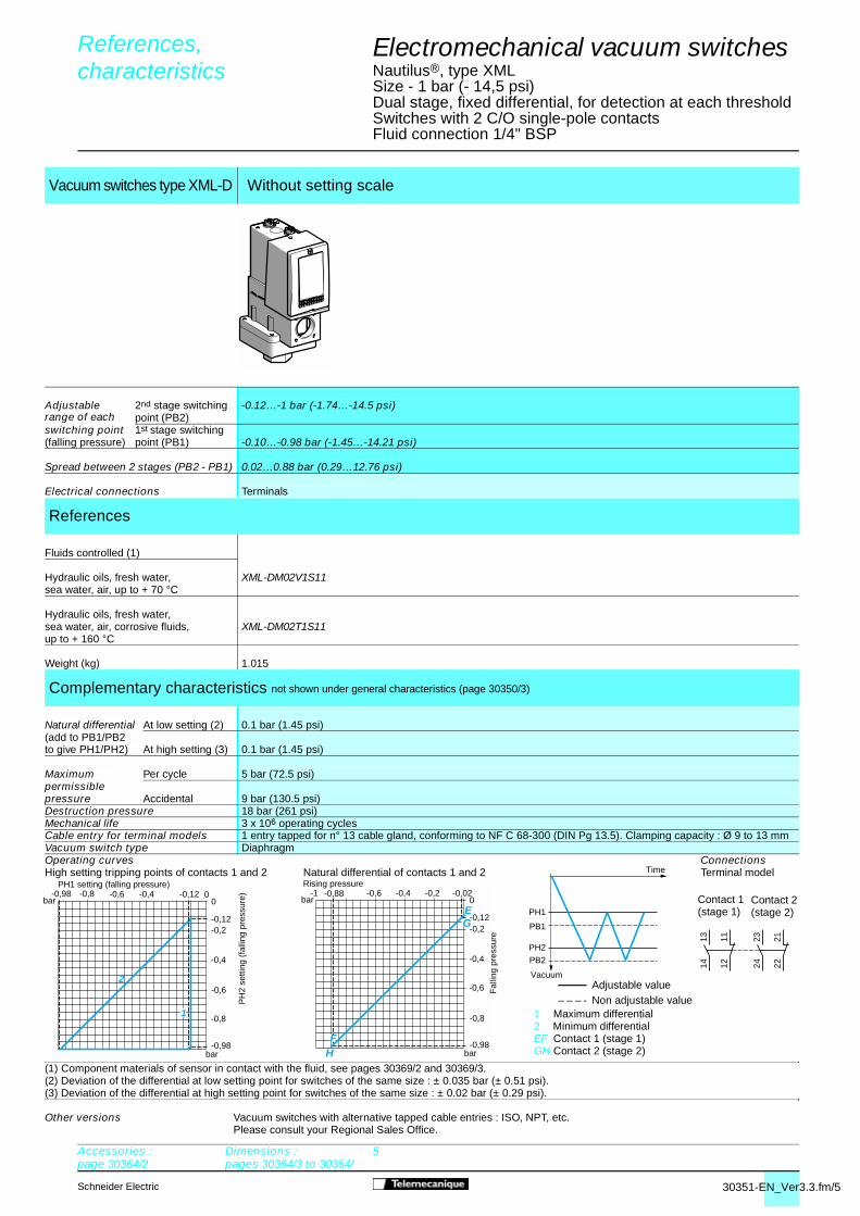
Electromechanical vacuum switches 4
Nautilus®, type XMLSize -1 bar (-14.5 psi)Fixed differential, for detection of a single thresholdSwitches with 1 C/O single-pole contactFluid connection 1/4" BSP
(1) Component materials of sensor in contact with the fluid, see pages 30369/2 and 30369/3.(2) Deviation of the differential at high and low setting points for switches of the same size : ± 0.05 bar (± 0.72 psi).
Vacuum switches type XML-A With setting scale Without setting scale
Adjustable range of switching -0.28…-1 bar (-4.06…-14.5 psi)point (PB) (falling pressure)
Electrical connections Terminals DIN connector Terminals DIN connector
References
Fluids controlled (1)
Hydraulic oils, fresh water, XML-AM01V2S11 XML-AM01V2C11 XML-AM01V1S11 XML-AM01V1C11sea water, air, up to + 70 °C
Hydraulic oils, fresh water, XML-AM01T2S11 XML-AM01T2C11 XML-AM01T1S11 XML-AM01T1C11sea water, air, corrosive fluids, up to + 160 °C
Weight (kg) 0.685 0.715 0.685 0.715
Complementary characteristics not shown under general characteristics (page 30350/3)
Natural differential At low setting (2) 0.24 bar (3.48 psi)(add to PBto give PH) At high setting (2) 0.24 bar (3.48 psi)
Maximum Per cycle 5 bar (72.5 psi)permissiblepressure Accidental 9 bar (130.5 psi)
Destruction pressure 18 bar (261 psi)
Mechanical life 3 x 10⁶ operating cycles
Cable entry for terminal models 1 entry tapped for n° 13 cable gland, conforming to NF C 68-300 (DIN Pg 13.5). Clamping capacity : Ø 9 to 13 mmConnector type for connector models DIN 43650A, 4-pin male. For suitable female connector, see page 30364/2Vacuum switch type DiaphragmOperating curves Connections
Terminal model
Connector model Switch connector pin view
Other versions Vacuum switches with alternative tapped cable entries : ISO, NPT, etc.Please consult your Regional Sales Office.
References, characteristics 0
Rising pressure
Time
Vacuum
��� Adjustable value ------ Non adjustable value
1 � 11 and 132 ��123 � 14
Accessories :page 30364/2
Dimensions :pages 30364/3 to 30364/
5
Fal
ling
pres
sure

30351-EN_Ver3.3.fm/3Schneider Electric
1314 12
11
321
bar
bar 0-0,01-0,2-0,4-0,6-0,87
-0,2-0,14
-0,4
-0,6
-0,8
-1
-1
1
2
PH
PB
Electromechanical vacuum switches 4
Nautilus®, type XMLSize -1 bar (-14.5 psi)Adjustable differential, for regulation between 2 thresholdsSwitches with 1 C/O single-pole contactFluid connection 1/4" BSP
(1) Component materials of sensor in contact with the fluid, see pages 30369/2 and 30369/3.(2) Deviation of the differential at high and low setting points for switches of the same size : ± 0.02 bar (± 0.29 psi).
Vacuum switches type XML-B With setting scale Without setting scale
Adjustable range of switching -0.14…-1 bar (-2.03…-14.5 psi)point (PB) (falling pressure)
Electrical connections Terminals DIN connector Terminals DIN connector
References
Fluids controlled (1)
Hydraulic oils, fresh water, XML-BM02V2S11 XML-BM02V2C11 XML-BM02V1S11 XML-BM02V1C11sea water, air, up to + 70 °C
Hydraulic oils, fresh water, XML-BM02T2S11 XML-BM02T2C11 XML-BM02T1S11 XML-BM02T1C11sea water, air, corrosive fluids,up to + 160 °C
Weight (kg) 1.015 1.030 1.015 1.030
Complementary characteristics not shown under general characteristics (page 30350/3)
Possible Min. at low setting (2) 0.13 bar (1.88 psi)differential(add to PB Min. at high setting (2) 0.13 bar (1.88 psi)to give PH)
Max. at high setting 0.8 bar (11.6 psi)
Maximum Per cycle 5 bar (72.5 psi)permissiblepressure Accidental 9 bar (130.5 psi)Destruction pressure 18 bar (261 psi) Mechanical life 3 x 10⁶ operating cyclesCable entry for terminal models 1 entry tapped for n° 13 cable gland, conforming to NF C 68-300 (DIN Pg 13.5). Clamping capacity : Ø 9 to 13 mmConnector type for connector models DIN 43650A, 4-pin male. For suitable female connector, see page 30364/2Vacuum switch type DiaphragmOperating curves Connections
Terminal model
Connector model Switch connector pin view
Other versions Vacuum switches with alternative tapped cable entries : ISO, NPT, etc.Please consult your Regional Sales Office.
References, characteristics 0
1 Maximum differential2 Minimum differential
Fal
ling
pres
sure
1 � 11 and 132 � 123 � 14
Accessories :page 30364/2
Dimensions :pages 30364/3 to 30364/
5
Rising pressure
Vacuum
Time
��
��
Adjustable value

30351-EN_Ver3.3.fm/4 Schneider Electric
PH
PB
bar
bar -0,010-0,14-0,4-0,6-0,86
-0,2
-0,4
-0,6
-0,8
2
1
2324 22
211314 12
11
Rising pressure
Fal
ling
pres
sure
Vacuum
Time
�
��
Adjustable value
Electromechanical vacuum switches 4
Nautilus®, type XMLSize -1 bar (-14.5 psi)Adjustable differential, for regulation between 2 thresholdsSwitches with 2 C/O single-pole contactsFluid connection 1/4" BSP
(1) Component materials of sensor in contact with the fluid, see pages 30369/2 and 30369/3.(2) Deviation of the differential at high and low setting points for switches of the same size : ± 0.02 bar (± 0.29 psi)
Vacuum switches type XML-C With setting scale
Adjustable range of switching -0.14…-1 bar (-2.03…-14.5 psi)point (PB) (falling pressure)
Electrical connections Terminals
References
Fluids controlled (1)
Hydraulic oils, fresh water, XML-CM02V2S11sea water, air, up to + 70 °C
Hydraulic oils, fresh water, XML-CM02T2S11sea water, air, corrosive fluids,up to + 160 °C
Weight (kg) 1.015
Complementary characteristics not shown under general characteristics (page 30350/3)
Possible Min. at low setting (2) 0.13 bar (1.89 psi)differential(add to PB Min. at high setting (2) 0.14 bar (2.03 psi)to give PH)
Max. at high setting 0.8 bar (11.6 psi)
Maximum Per cycle 5 bar (72.5 psi)permissiblepressure Accidental 9 bar (130.5 psi)
Destruction pressure 18 bar (261 psi) Mechanical life 3 x 10⁶ operating cyclesCable entry for terminal models 1 entry tapped for n° 13 cable gland, conforming to NF C 68-300 (DIN Pg 13.5). Clamping capacity : Ø 9 to 13 mmVacuum switch type DiaphragmOperating curves Connections
Terminal model
Other versions Vacuum switches with alternative tapped cable entries : ISO, NPT, etc.Please consult your Regional Sales Office.
References, characteristics 0
1 Maximum differential2 Minimum differential
Accessories :page 30364/2
Dimensions :pages 30364/3 to 30364/
5
30351-EN_Ver3.3.fm/5Schneider Electric
bar
bar 00-0,12-0,4-0,6-0,98
-0,2-0,12
-0,4
-0,6
-0,8
-0,98
2
1
-0,8
bar
bar 0-0,02-0,2-0,4-0,6-0,88
-0,2-0,12
-0,4
-0,6
-0,8
-0,98
-1
E
H
G
F
PH1
PH2
PB2
PB1
Time
2324 22
211314 12
11
Accessories :page 30364/2
Dimensions :pages 30364/3 to 30364/
5
Electromechanical vacuum switches 4
Nautilus®, type XMLSize - 1 bar (- 14,5 psi)Dual stage, fixed differential, for detection at each thresholdSwitches with 2 C/O single-pole contactsFluid connection 1/4" BSP
(1) Component materials of sensor in contact with the fluid, see pages 30369/2 and 30369/3.(2) Deviation of the differential at low setting point for switches of the same size : ± 0.035 bar (± 0.51 psi).(3) Deviation of the differential at high setting point for switches of the same size : ± 0.02 bar (± 0.29 psi).
Vacuum switches type XML-D Without setting scale
Adjustable range of each
2nd stage switching point (PB2)
-0.12…-1 bar (-1.74…-14.5 psi)
switching point 1st stage switching (falling pressure) point (PB1) -0.10…-0.98 bar (-1.45…-14.21 psi)
Spread between 2 stages (PB2 - PB1) 0.02…0.88 bar (0.29…12.76 psi)
Electrical connections Terminals
References
Fluids controlled (1)
Hydraulic oils, fresh water, XML-DM02V1S11sea water, air, up to + 70 °C
Hydraulic oils, fresh water,sea water, air, corrosive fluids, XML-DM02T1S11up to + 160 °C
Weight (kg) 1.015
Complementary characteristics not shown under general characteristics (page 30350/3)
Natural differential At low setting (2) 0.1 bar (1.45 psi)(add to PB1/PB2to give PH1/PH2) At high setting (3) 0.1 bar (1.45 psi)
Maximum Per cycle 5 bar (72.5 psi)permissiblepressure Accidental 9 bar (130.5 psi)Destruction pressure 18 bar (261 psi) Mechanical life 3 x 10⁶ operating cyclesCable entry for terminal models 1 entry tapped for n° 13 cable gland, conforming to NF C 68-300 (DIN Pg 13.5). Clamping capacity : Ø 9 to 13 mmVacuum switch type DiaphragmOperating curves ConnectionsHigh setting tripping points of contacts 1 and 2 Natural differential of contacts 1 and 2
Rising pressure Terminal model
Other versions Vacuum switches with alternative tapped cable entries : ISO, NPT, etc.Please consult your Regional Sales Office.
References, characteristics 0
Contact 1(stage 1)
Contact 2(stage 2)
PH
2 se
tting
(fa
lling
pre
ssur
e)
���Adjustable value
– – – - Non adjustable value1 Maximum differential2 Minimum differential EF Contact 1 (stage 1)GH Contact 2 (stage 2)
PH1 setting (falling pressure)
Vacuum
Fal
ling
pres
sure

30352-EN_Ver3.4.fm/2 Schneider Electric
1314 12
11
mbar
mbar 0-2-40-80-120-160
-40
-20
-80
-120
-160
-200
-182
1
2
-20
PH
PB
Electromechanical vacuum switches 4
Nautilus®, type XMLSize -200 mbar (-2.9 psi)Adjustable differential, for regulation between 2 thresholdsSwitches with 1 C/O single-pole contactFluid connection 1/4" BSP
(1) Component materials of sensor in contact with the fluid, see pages 30369/2 and 30369/3.(2) Deviation of the differential at high and low setting points for switches of the same size : ± 2 mbar (0.29 psi).
Vacuum switches type XML-B With setting scale
Adjustable range of switching -20…-200 mbar (-0.29…-2.9 psi)point (PB) (falling pressure)
Electrical connections Terminals
References
Fluids controlled (1)
Hydraulic oils, air, XML-BM03R2S11up to + 160 °C
Fresh water, sea water, corrosive XML-BM03S2S11fluids, up to + 160 °C
Weight (kg) 3.310
Complementary characteristics not shown under general characteristics (page 30350/3)
Possible Min. at low setting (2) 18 mbar (0.26 psi)differential(add to PB Min. at high setting (2) 18 mbar (0.26 psi)to give PH)
Max. at high setting 180 mbar (2.6 psi)
Maximum Per cycle 1 bar (14.5 psi)permissiblepressure Accidental 2 bar (29 psi)Destruction pressure 3.5 bar (50.75 psi)Mechanical life 3 x 10⁶ operating cycles
Cable entry for terminal models 1 entry tapped for n° 13 cable gland, conforming to NF C 68-300 (DIN Pg 13.5). Clamping capacity : Ø 9 to 13 mmVacuum switch type DiaphragmOperating curves Connections
Terminal model
Other versions Vacuum switches with alternative tapped cable entries : ISO, NPT, etc.Please consult your Regional Sales Office.
References, characteristics 0
Vacuum
Time
Adjustable value
1 Maximum differential2 Minimum differential
Rising pressure
Fal
ling
pres
sure
Accessories :page 30364/2
Dimensions :pages 30364/3 to 30364/5
30352-EN_Ver3.4.fm/3Schneider Electric
1314 12
11PH
PB
mbar
mbar
010 30 4640
10
20
30
1,2
2,6
40
50
2
1
20
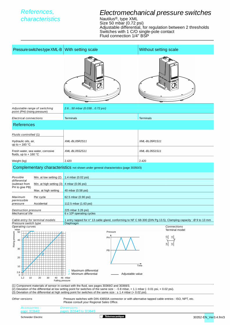
Electromechanical pressure switches 4
Nautilus®, type XMLSize 50 mbar (0.72 psi)Adjustable differential, for regulation between 2 thresholds Switches with 1 C/O single-pole contactFluid connection 1/4" BSP
(1) Component materials of sensor in contact with the fluid, see pages 30369/2 and 30369/3.(2) Deviation of the differential at low setting point for switches of the same size : - 0.8 mbar, + 1.1 mbar (- 0.01 psi, + 0.02 psi).
Pressure switches type XML-B With setting scale Without setting scale
Adjustable range of switching 2.6…50 mbar (0.038…0.72 psi)point (PH) (rising pressure)
Electrical connections Terminals Terminals
References
Fluids controlled (1)
Hydraulic oils, air, XML-BL05R2S11 XML-BL05R1S11up to + 160 °C
Fresh water, sea water, corrosive XML-BL05S2S11 XML-BL05S1S11fluids, up to + 160 °C
Weight (kg) 2.420 2.420
Complementary characteristics not shown under general characteristics (page 30350/3)
Possible Min. at low setting (2) 1.4 mbar (0.02 psi)differential(subtract from Min. at high setting (3) 4 mbar (0.06 psi)PH to give PB)
Max. at high setting 40 mbar (0.58 psi)
Maximum Per cycle 62.5 mbar (0.90 psi)permissiblepressure Accidental 112.5 mbar (1.63 psi)
Destruction pressure 225 mbar 3.26 psi)Mechanical life 6 x 10⁶ operating cycles
Cable entry for terminal models 1 entry tapped for n° 13 cable gland, conforming to NF C 68-300 (DIN Pg 13.5). Clamping capacity : Ø 9 to 13 mmPressure switch type DiaphragmOperating curves Connections
Terminal model
(3) Deviation of the differential at high setting point for switches of the same size : ± 1.4 mbar (+ 0.02 psi).
Other versions Pressure switches with DIN 43650A connector or with alternative tapped cable entries : ISO, NPT, etc.Please consult your Regional Sales Office.
References, characteristics 0
Accessories :page 30364/2
Dimensions :pages 30364/3 to 30364/5
1 Maximum differential2 Minimum differential
Ris
ing
pres
sure
Falling pressure
Adjustable value
Time
Pressure
30353-EN_Ver3.3.fm/2 Schneider Electric
1314 12
11
4,5-1-1
-0,5
0,5
1 2 3 4 4,5 5
4
5
0
3
2
1
0
bar
bar
21
321
PH1
PB1
PH2
PB2
PH3
PB3
0
1
2
3
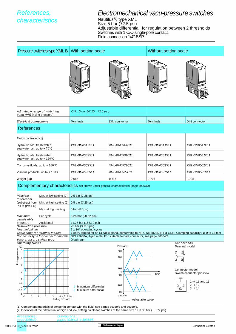
Electromechanical vacu-pressure switches4
Nautilus®, type XMLSize 5 bar (72.5 psi)Adjustable differential, for regulation between 2 thresholdsSwitches with 1 C/O single-pole contact.Fluid connection 1/4" BSP
(1) Component materials of sensor in contact with the fluid, see pages 30369/2 and 30369/3.(2) Deviation of the differential at high and low setting points for switches of the same size : ± 0.05 bar (± 0.72 psi).
Pressure switches type XML-B With setting scale Without setting scale
Adjustable range of switching -0.5…5 bar (-7.25…72.5 psi)point (PH) (rising pressure)
Electrical connections Terminals DIN connector Terminals DIN connector
References
Fluids controlled (1)
Hydraulic oils, fresh water, XML-BM05A2S11 XML-BM05A2C11 XML-BM05A1S11 XML-BM05A1C11sea water, air, up to + 70°C
Hydraulic oils, fresh water, XML-BM05B2S11 XML-BM05B2C11 XML-BM05B1S11 XML-BM05B1C11sea water, air, up to + 160°C
Corrosive fluids, up to + 160°C XML-BM05C2S11 XML-BM05C2C11 XML-BM05C1S11 XML-BM05C1C11
Viscous products, up to + 160°C XML-BM05P2S11 XML-BM05P2C11 XML-BM05P1S11 XML-BM05P1C11
Weight (kg) 0.685 0.715 0.705 0.735
Complementary characteristics not shown under general characteristics (page 30350/3)
Possible Min. at low setting (2) 0.5 bar (7.25 psi)differential(substract from Min. at high setting (2) 0.5 bar (7.25 psi)PH to give PB)
Max. at high setting 6 bar (87 psi)
Maximum Per cycle 6.25 bar (90.62 psi)permissiblepressure Accidental 11.25 bar (163.12 psi)Destruction pressure 23 bar (333.5 psi)Mechanical life 3 x 10⁶ operating cyclesCable entry for terminal models 1 entry tapped for n° 13 cable gland, conforming to NF C 68-300 (DIN Pg 13.5). Clamping capacity : Ø 9 to 13 mmConnector type for connector models DIN 43650A, 4-pin male. For suitable female connector, see page 30364/2Vacu-pressure switch type DiaphragmOperating curves Connections
Terminal model
Connector modelSwitch connector pin view
References, characteristics 0
____ Adjustable value
Accessories :page 30364/2
Dimensions :pages 30364/3 to 30364/5
Ris
ing
pres
sure
Falling pressure
1 Maximum differential2 Minimum differential
Vacuum
Time
Pressure
1 � 11 and 132 � 123 � 14

30353-EN_Ver3.3.fm/3Schneider Electric
4,55-1-1
-0,55
0,5
1 2 3 4 5
4
5
0
3
2
1
0
bar
bar
21
PH1
PB1
PH2
PB2
PH3
PB3
0
1
2
3
2324 22
211314 12
11
Electromechanical vacu-pressure switches4
Nautilus®, type XMLSize 5 bar (72.5 psi)Adjustable differential, for regulation between 2 thresholdsSwitches with 2 C/O single-pole contactsFluid connection 1/4" BSP
(1) Component materials of sensor in contact with the fluid, see pages 30369/2 and 30369/3.(2) Deviation of the differential at high and low setting points for switches of the same size : ± 0.1 bar (± 1.45 psi).
Pressure switches type XML-C With setting scale
Adjustable range of switching -0.55…5 bar (-7.97…72.5 psi)point (PH) (rising pressure)
Electrical connections Terminals
References
Fluids controlled (1)
Hydraulic oils, fresh water, XML-CM05A2S11sea water, air, up to + 70 °C
Hydraulic oils, fresh water, XML-CM05B2S11sea water, air, up to + 160 °C
Corrosive fluids, up to + 160 °C XML-CM05C2S11
Weight (kg) 0.685
Complementary characteristics not shown under general characteristics (page 30350/3)
Possible Min. at low setting (2) 0.45 bar (6.52 psi)differential(subtract from Min. at high setting (2) 0.45 bar (6.52 psi)PH to give PB)
Max. at high setting 6 bar (87 psi)
Maximum Per cycle 6.25 bar (90.62 psi)permissiblepressure Accidental 11.25 bar (163.12 psi)Destruction pressure 23 bar (333.5 psi)Mechanical life 3 x 10⁶ operating cyclesCable entry for terminal models 1 entry tapped for n° 13 cable gland, conforming to NF C 68-300 (DIN Pg 13.5). Clamping capacity : Ø 9 to 13 mmVacu-pressure switch type DiaphragmOperating curves Connections
Terminal model
Other versions Vacu-pressure switches with alternative tapped cable entries : ISO, NPT, etc.Please consult your Regional Sales Office.
References, characteristics 0
Accessories :page 30364/2
Dimensions :pages 30364/3 to 30364/5
Ris
ing
pres
sure
Falling pressure
1 Maximum differential2 Minimum differential
Vacuum
Pressure
____ Adjustable value
Time

30379-EN_Ver4.3.fm/2 Schneider Electric
References, 0
characteristics 0
Electromechanical pressure switches 4
Nautilus®, type XMLSize 350 mbar (5.07 psi)Adjustable differential, for regulation between 2 thresholdsSwitches with 1 C/O single-pole contactFluid connection 1/4" BSP
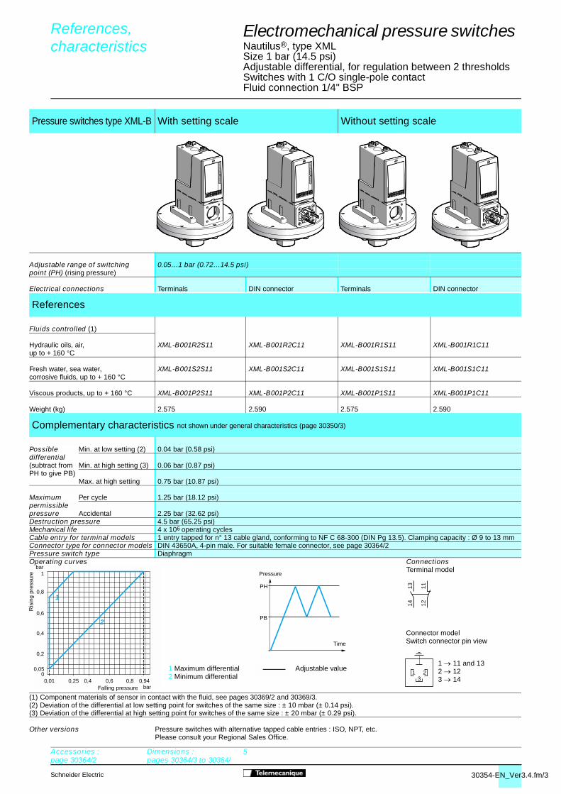
Pressure switches type XML B With setting scale 30 bar (435 psi) overpressureWith setting scale
Adjustable range of switchingpoint (PH) (rising pressure)
45…350 mbar (0.65…5.07 psi) 42…330 mbar (0.61…4.78 psi)
Electrical connections Terminals DIN connector Terminals
References
Fluids controlled (1)
Hydraulic oils, air,up to + 160 °C
XML BL35R2S11 XML BL35R2C11 XML BS35R2S11
Fresh water, sea water, corrosive fluids, up to + 160 °C
XML BL35S2S11 XML BL35S2C11 –
Viscous products, up to + 160 °C
XML BL35P2S11 XML BL35P2C11 –
Weight (kg) 2.575 2.590 3.500
Complementary characteristics not shown under general characteristics (page 30350/3)
Possible differentialsubtract fromPH to give PB
Min. at low setting (2) 42 mbar (0.60 psi) 33 mbar (0.48 psi)Min. at high setting (3) 50 mbar (0.72 psi) 58 mbar (0.84 psi)Max. at high setting 300 mbar (4.35 psi) 250 mbar (3.62 psi)
Maximum permissible pressure
Per cycle 1.25 bar (18.12 psi) 30 bar (435 psi)Accidental 2.25 bar (32.62 psi) 37.5 bar (543.75 psi)
Destruction pressure 4.5 bar (65.25 psi) 67.5 bar (978.75 psi)Mechanical life Millions of operating
cycles4 2
Cable entry for terminal models 1 entry tapped for n° 13 cable gland, conforming to NF C 68-300 (DIN Pg 13.5). Clamping capacity : Ø 9 to 13 mmConnector type for connector models DIN 43650A, 4-pin male. For suitable female connector, see page 30364/2Pressure switch type Diaphragm(1) Component materials of sensor in contact with the fluid, see pages 30369/2 and 30369/3.(2) Deviation of the differential at low setting point for switches of the same size : - 8 mbar, + 3 mbar (- 0.12 psi, + 0.04 psi).(3) Deviation of the differential at high setting point for switches of the same size : ± 8 mbar (± 0.11 psi).
Operating curves Connections
1 Maximum differential2 Minimum differential
Adjustable value
Terminal model
Connector model Switch connector pin view
1 � 11 and 132 � 123 � 14
Other versions Pressure switches with alternative tapped cable entries : ISO, NPT, etc.Please consult your Regional Sales Office.
3 50 mbar
mbar
0100 200 300
100
200
300
350
45
2
1
Ris
ing
pres
sure
Falling pressure
Pressure
Time
PH
PB
1314 12
11
321
Accessories :page 30364/2
Dimensions :pages 30364/3 to 30364/5
30379-EN_Ver4.3.fm/3Schneider Electric
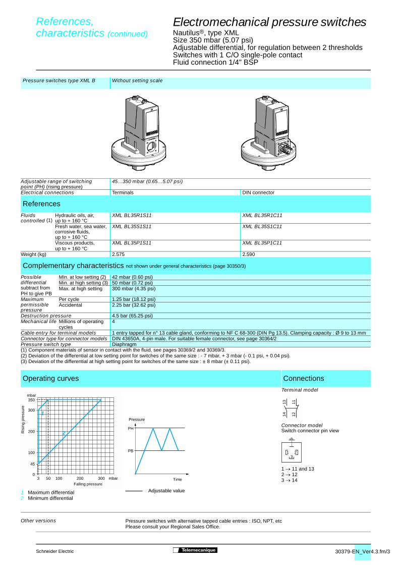
Electromechanical pressure switches 4
Nautilus®, type XMLSize 350 mbar (5.07 psi)Adjustable differential, for regulation between 2 thresholdsSwitches with 1 C/O single-pole contactFluid connection 1/4" BSP
Pressure switches type XML B Without setting scale
Adjustable range of switchingpoint (PH) (rising pressure)
45…350 mbar (0.65…5.07 psi)
Electrical connections Terminals DIN connector
References
Fluids controlled (1)
Hydraulic oils, air,up to + 160 °C
XML BL35R1S11 XML BL35R1C11
Fresh water, sea water, corrosive fluids, up to + 160 °C
XML BL35S1S11 XML BL35S1C11
Viscous products, up to + 160 °C
XML BL35P1S11 XML BL35P1C11
Weight (kg) 2.575 2.590
Complementary characteristics not shown under general characteristics (page 30350/3)
Possible differentialsubtract fromPH to give PB
Min. at low setting (2) 42 mbar (0.60 psi)Min. at high setting (3) 50 mbar (0.72 psi)Max. at high setting 300 mbar (4.35 psi)
Maximum permissible pressure
Per cycle 1.25 bar (18.12 psi)Accidental 2.25 bar (32.62 psi)
Destruction pressure 4.5 bar (65.25 psi)Mechanical life Millions of operating
cycles4
Cable entry for terminal models 1 entry tapped for n° 13 cable gland, conforming to NF C 68-300 (DIN Pg 13.5). Clamping capacity : Ø 9 to 13 mmConnector type for connector models DIN 43650A, 4-pin male. For suitable female connector, see page 30364/2 Pressure switch type Diaphragm(1) Component materials of sensor in contact with the fluid, see pages 30369/2 and 30369/3.(2) Deviation of the differential at low setting point for switches of the same size : - 7 mbar, + 3 mbar (- 0.1 psi, + 0.04 psi).(3) Deviation of the differential at high setting point for switches of the same size : ± 8 mbar (± 0.11 psi).
Operating curves Connections
1 Maximum differential2 Minimum differential
Adjustable value
Terminal model
Connector modelSwitch connector pin view
1 � 11 and 132 � 123 � 14
Other versions Pressure switches with alternative tapped cable entries : ISO, NPT, etcPlease consult your Regional Sales Office.
3 50 mbar
mbar
0100 200 300
100
200
300
350
45
2
1
Ris
ing
pres
sure
Falling pressure
Pressure
Time
PH
PB
1314 12
11
321
References, 0
characteristics (continued) 0
30379-EN_Ver4.3.fm/4 Schneider Electric
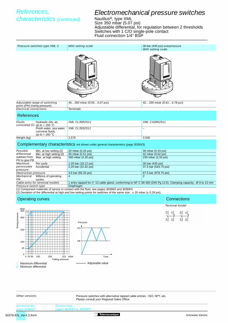
Electromechanical pressure switches 4
Nautilus®, type XMLSize 350 mbar (5.07 psi)Adjustable differential, for regulation between 2 thresholdsSwitches with 1 C/O single-pole contactFluid connection 1/4" BSP
Pressure switches type XML C With setting scale 30 bar (435 psi) overpressureWith setting scale
Adjustable range of switchingpoint (PH) (rising pressure)
45…350 mbar (0.65…5.07 psi) 42…330 mbar (0.61…4.78 psi)
Electrical connections Terminals
References
Fluids controlled (1)
Hydraulic oils, air,up to + 160 °C
XML CL35R2S11 XML CS35R2S11
Fresh water, sea water, corrosive fluids, up to + 160 °C
XML CL35S2S11 –
Weight (kg) 2.575 3.500
Complementary characteristics not shown under general characteristics (page 30350/3)
Possible differentialsubtract fromPH to give PB
Min. at low setting (2) 20 mbar (0.29 psi) 30 mbar (0.43 psi)Min. at high setting (2) 35 mbar (0.51 psi) 42 mbar (0.62 psi)Max. at high setting 300 mbar (4.35 psi) 230 mbar (3.33 psi)
Maximum permissible pressure
Per cycle 1.25 bar (18.12 psi) 30 bar (435 psi)Accidental 2.25 bar (32.62 psi) 37.5 bar (543.75 psi)
Destruction pressure 4.5 bar (65.25 psi) 67.5 bar (978.75 psi)Mechanical life
Millions of operating cycles
4 2
Cable entry for terminal models 1 entry tapped for n° 13 cable gland, conforming to NF C 68-300 (DIN Pg 13.5). Clamping capacity : Ø 9 to 13 mmPressure switch type Diaphragm(1) Component materials of sensor in contact with the fluid, see pages 30369/2 and 30369/3.(2) Deviation of the differential at high and low setting points for switches of the same size : ± 20 mbar (± 0.29 psi).
Operating curves Connections
1 Maximum differential2 Minimum differential
Adjustable value
Terminal model
Other versions Pressure switches with alternative tapped cable entries : ISO, NPT, etc.Please consult your Regional Sales Office.
0 25 50 mbar
mbar
0100 200 315
100
200
300
350
45
2
1
Ris
ing
pres
sure
Falling pressure
Pressure
Time
PH
PB
2324 22
211314 12
11
References, 0
characteristics (continued) 0
Accessories :page 30364/2
Dimensions :pages 30364/3 to 30364/5
30354-EN_Ver3.4.fm/2 Schneider Electric
1314 12
11
321
bar
bar
0
0,8
0,6
0,4
0,2
0,03
1
0,960,80,60,40,20,01
PH
PB
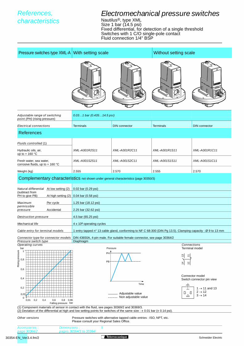
Electromechanical pressure switches 4
Nautilus®, type XMLSize 1 bar (14.5 psi)Fixed differential, for detection of a single thresholdSwitches with 1 C/O single-pole contactFluid connection 1/4" BSP
(1) Component materials of sensor in contact with the fluid, see pages 30369/2 and 30369/3.(2) Deviation of the differential at high and low setting points for switches of the same size : ± 0.01 bar (± 0.14 psi).
Pressure switches type XML-A With setting scale Without setting scale
Adjustable range of switching 0.03…1 bar (0.435…14.5 psi)point (PH) (rising pressure)
Electrical connections Terminals DIN connector Terminals DIN connector
References
Fluids controlled (1)
Hydraulic oils, air, XML-A001R2S11 XML-A001R2C11 XML-A001R1S11 XML-A001R1C11up to + 160 °C
Fresh water, sea water, XML-A001S2S11 XML-A001S2C11 XML-A001S1S11 XML-A001S1C11corrosive fluids, up to + 160 °C
Weight (kg) 2.555 2.570 2.555 2.570
Complementary characteristics not shown under general characteristics (page 30350/3)
Natural differential At low setting (2) 0.02 bar (0.29 psi)(subtract fromPH to give PB) At high setting (2) 0.04 bar (0.58 psi)
Maximum Per cycle 1.25 bar (18.12 psi)permissiblepressure Accidental 2.25 bar (32.62 psi)
Destruction pressure 4.5 bar (65.25 psi)
Mechanical life 4 x 10⁶ operating cycles
Cable entry for terminal models 1 entry tapped n° 13 cable gland, conforming to NF C 68-300 (DIN Pg 13.5). Clamping capacity : Ø 9 to 13 mm
Connector type for connector models DIN 43650A, 4-pin male. For suitable female connector, see page 30364/2Pressure switch type DiaphragmOperating curves Connections
Terminal model
Connector modelSwitch connector pin view
Other versions Pressure switches with alternative tapped cable entries : ISO, NPT, etc.Please consult your Regional Sales Office.
References, characteristics 0
Pressure
Time
1 � 11 and 132 � 123 � 14
Accessories :page 30364/2
Dimensions : pages 30364/3 to 30364/
5
Falling pressure
Ris
ing
pres
sure
Adjustable valueNon adjustable value
30354-EN_Ver3.4.fm/3Schneider Electric
1314 12
11
321
bar
bar
00,05
0,8
0,6
0,4
0,2
1
0,940,80,60,40,250,01
1
2
PH
PB
Electromechanical pressure switches 4
Nautilus®, type XMLSize 1 bar (14.5 psi)Adjustable differential, for regulation between 2 thresholdsSwitches with 1 C/O single-pole contactFluid connection 1/4" BSP
(1) Component materials of sensor in contact with the fluid, see pages 30369/2 and 30369/3.(2) Deviation of the differential at low setting point for switches of the same size : ± 10 mbar (± 0.14 psi).(3) Deviation of the differential at high setting point for switches of the same size : ± 20 mbar (± 0.29 psi).
Pressure switches type XML-B With setting scale Without setting scale
Adjustable range of switching 0.05…1 bar (0.72…14.5 psi)point (PH) (rising pressure)
Electrical connections Terminals DIN connector Terminals DIN connector
References
Fluids controlled (1)
Hydraulic oils, air, XML-B001R2S11 XML-B001R2C11 XML-B001R1S11 XML-B001R1C11up to + 160 °C
Fresh water, sea water, XML-B001S2S11 XML-B001S2C11 XML-B001S1S11 XML-B001S1C11corrosive fluids, up to + 160 °C
Viscous products, up to + 160 °C XML-B001P2S11 XML-B001P2C11 XML-B001P1S11 XML-B001P1C11
Weight (kg) 2.575 2.590 2.575 2.590
Complementary characteristics not shown under general characteristics (page 30350/3)
Possible Min. at low setting (2) 0.04 bar (0.58 psi)differential(subtract from Min. at high setting (3) 0.06 bar (0.87 psi)PH to give PB)
Max. at high setting 0.75 bar (10.87 psi)
Maximum Per cycle 1.25 bar (18.12 psi)permissiblepressure Accidental 2.25 bar (32.62 psi)Destruction pressure 4.5 bar (65.25 psi)Mechanical life 4 x 10⁶ operating cyclesCable entry for terminal models 1 entry tapped for n° 13 cable gland, conforming to NF C 68-300 (DIN Pg 13.5). Clamping capacity : Ø 9 to 13 mmConnector type for connector models DIN 43650A, 4-pin male. For suitable female connector, see page 30364/2Pressure switch type DiaphragmOperating curves Connections
Terminal model
Connector modelSwitch connector pin view
Other versions Pressure switches with alternative tapped cable entries : ISO, NPT, etc.Please consult your Regional Sales Office.
References, characteristics 0
Pressure
Adjustable value1 Maximum differential
2 Minimum differential
1 � 11 and 132 � 123 � 14
Accessories :page 30364/2
Dimensions : pages 30364/3 to 30364/
5
Ris
ing
pres
sure
Falling pressure
Time

30354-EN_Ver3.4.fm/4 Schneider Electric
PH
PB
bar
bar
00,05
0,6
0,4
0,2
1
0,960,80,60,40,20,02
1
2
2324 22
211314 12
11
Electromechanical pressure switches 4
Nautilus®, type XMLSize 1 bar (14.5 psi)Adjustable differential, for regulation between 2 thresholdsSwitches with 2 C/O single-pole contactsFluid connection 1/4" BSP
(1) Component materials of sensor in contact with the fluid, see pages 30369/2 and 30369/3.(2) Deviation of the differential at low setting point for switches of the same size : ± 0.01 bar (± 0.14 psi).(3) Deviation of the differential at high setting point for switches of the same size : ± 0.03 bar (± 0.43 psi).
Pressure switches type XML-C With setting scale
Adjustable range of switching 0.05…1 bar (0.725…14.5 psi)point (PH) (rising pressure)
Electrical connections Terminals
References
Fluids controlled (1)
Hydraulic oils, air, XML-C001R2S11up to + 160 °C
Fresh water, sea water, XML-C001S2S11corrosive fluids, up to + 160 °C
Weight (kg) 2.555
Complementary characteristics not shown under general characteristics (page 30350/3)
Possible Min. at low setting (2) 0.03 bar (0.43 psi)differential(subtract from Min. at high setting (3) 0.04 bar (0.58 psi)PH to give PB)
Max. at high setting 0.8 bar (11.6 psi)
Maximum Per cycle 1.25 bar (18.12 psi)permissiblepressure Accidental 2.25 bar (32.62 psi)
Destruction pressure 4.5 bar (65.25 psi)Mechanical life 4 x 10⁶ operating cyclesCable entry for terminal models 1 entry tapped for n° 13 cable gland, conforming to NF C 68-300 (DIN Pg 13.5). Clamping capacity : Ø 9 to 13 mm.Pressure switch type DiaphragmOperating curves Connections
Terminal model
Other versions Pressure switches with alternative tapped cable entries : ISO, NPT, etc.Please consult your Regional Sales Office.
References, characteristics 0
Accessories :page 30364/2
Dimensions : pages 30364/3 to 30364/
5
Ris
ing
pres
sure
Falling pressure
1 Maximum differential2 Minimum differential
Time
Pressure
Adjustable value

30354-EN_Ver3.4.fm/5Schneider Electric
bar
bar
0
0,12
0,77
0,6
0,4
0,2
1
0,920,80,60,40,270,04
1
2
bar
bar
0
0,8
0,92
0,6
0,4
0,2
0,040,12
1
0,85 0,930,60,40,20,01 0,09
E
G
F
H
2324 22
211314 12
11
PH2
PH1
PB1
PB2
Electromechanical pressure switches 4
Nautilus®, type XMLSize 1 bar (14.5 psi)Dual stage, fixed differential, for detection at each thresholdSwitches with 2 C/O single-pole contacts Fluid connection 1/4" BSP
(1) Component materials of sensor in contact with the fluid, see pages 30369/2 and 30369/3.(2) Deviation of the differential at low setting point for switches of the same size : ± 0.01 bar (± 0.14 psi).(3) Deviation of the differential at high setting point for switches of the same size : ± 0.04 mbar (± 0.58 psi).
Pressure switches type XML-D Without setting scale
Adjustable 2nd stage switching 0.12…1 bar (1.74…14.5 psi)range of each point (PH2)switching point 1st stage switching(rising pressure) point (PH1) 0.04…0.92 bar (0.58…13.34 psi)
Spread between 2 stages (PH2 - PH1) 0.08…0.73 bar (1.16…10.59 psi)
Electrical connections Terminals
References
Fluids controlled (1)
Hydraulic oils, air, XML-D001R1S11up to + 160 °C
Fresh water, sea water, XML-D001S1S11corrosive fluids, up to + 160 °C
Weight (kg) 2.575
Complementary characteristics not shown under general characteristics (page 30350/3)
Natural differential At low setting (2) 0.03 bar (0.44 psi)(subtract from PH1/PH2to give PB1/PB2) At high setting (3) 0.07 bar (1.02 psi)
Maximum Per cycle 1.25 bar (18.12 psi)permissiblepressure Accidental 2.25 bar (32.62 psi)Destruction pressure 4.5 bar (65.25 psi)Mechanical life 4 x 10⁶ operating cyclesCable entry for terminal models 1 entry tapped for n° 13 cable gland, conforming to NF C 68-300 (DIN Pg 13.5). Clamping capacity : Ø 9 to 13 mmPressure switch type DiaphragmOperating curves ConnectionsHigh setting tripping points of contacts 1 and 2 Natural differential of contacts 1 and 2 Terminal model
1 Maximum differential2 Minimum differentialEF Contact 1 (stage 1)GH Contact 2 (stage 2)
Other versions Pressure switches with alternative tapped cable entries : ISO, NPT, etc. Please consult your Regional Sales Office.
References, characteristics 0
Time
Pressure
PH
2 se
tting
(ris
ing
pres
sure
)
Ris
ing
pres
sure Contact 2
(stage 2)Contact 1(stage 1)
Accessories :page 30364/2
Dimensions : pages 30364/3 to 30364/
5
Falling pressurePH1 setting (rising pressure)
Adjustable valueNon adjustable value

30355-EN_Ver5.2.fm/2 Schneider Electric
Electromechanical pressure switches 4
Nautilus®, type XMLSize 2.5 bar (36.25 psi)Fixed differential, for detection of a single thresholdSwitches with 1 C/O single-pole contactFluid connection 1/4" BSP
Pressure switches type XML-A With setting scale Without setting scale
Adjustable range of switchingpoint (PH) (rising pressure)
0.15…2.5 bar (2.17…36.25 psi)
Electrical connections Terminals DIN connector Terminals DIN connector
References
Fluids controlled (1)
Hydraulic oils, fresh water, sea water, air, up to + 70 °C
XML A002A2S11 XML A002A2C11 XML A002A1S11 XML A002A1C11
Hydraulic oils, fresh water, sea water, air, up to + 160 °C
XML A002B2S11 XML A002B2C11 XML A002B1S11 XML A002B1C11
Corrosive fluids, up to + 160 °C
XML A002C2S11 XML A002C2C11 XML A002C1S11 XML A002C1C11
Weight (kg) 0.995 1.010 0.995 1.010
Complementary characteristics not shown under general characteristics (page 30350/3)
Natural differential(subtract from PH to give PB)
At low setting (2) 0.13 bar (1.88 psi)At high setting (2) 0.13 bar (1.88 psi)
Maximum permissiblepressure
Per cycle 5 bar (72.5 psi)Accidental 9 bar (130.5 psi)
Destruction pressure 18 bar (261 psi)Mechanical life
Millions of operating cycles
8
Cable entry for terminal models 1 entry tapped for n° 13 cable gland, conforming to NF C 68 300 (DIN Pg 13.5). Clamping capacity : Ø 9 to 13 mmConnector type for connector models DIN 43650A, 4-pin male. For suitable female connector, see page 30364/2Pressure switch type Diaphragm(1) Component materials of sensor in contact with the fluid, see pages 30369/2 and 30369/3.(2) Deviation of the differential at high and low setting points for switches of the same size : ± 0.03 bar (± 0.43 psi).
Operating curves Connections
Adjustable valueNon adjustable value
Terminal model
Connector modelSwitch connector pin view
1 � 11 and 132 � 123 � 14
Other versions Pressure switches with alternative tapped cable entries : ISO, NPT, etc.Please consult your Regional Sales Office.
Ris
ing
pres
sure
Falling pressure0,02
00,15
2 2,37
2
2,5
1
1
bar
bar
Pressure
Time
PH
PB
1314 12
11
321
References, characteristics 0
Accessories :page 30364/2
Dimensions : pages 30364/3 to 30364/
5

30355-EN_Ver5.2.fm/3Schneider Electric
Electromechanical pressure switches 4
Nautilus®, type XMLSize 2.5 bar (36.25 psi)Adjustable differential, for regulation between 2 thresholdsSwitches with 1 C/O single-pole contactFluid connection 1/4" BSP
Pressure switches type XML-B With setting scale Without setting scale 30 bar (435 psi) overpressureWith setting scale
Adjustable range of switching point (PH) (rising pressure)
0.3…2.5 bar (4.35…36.25 psi)
Electrical connections Terminals DIN connector Terminals DIN connector Terminals
References
Fluids controlled (1)
Hydraulic oils, fresh water, sea water, air, up to + 70° C
XML B002A2S11 XML B002A2C11 XML B002A1S11 XML B002A1C11 –
Hydraulic oils, fresh water, sea water, air, up to + 160° C
XML B002B2S11 XML B002B2C11 XML B002B1S11 XML B002B1C11 XML BS02B2S11
Corrosive fluids, up to + 160° C
XML B002C2S11 XML B002C2C11 XML B002C1S11 XML B002C1C11 –
Weight (kg) 1.015 1.030 1.015 1.030 3.500
Complementary characteristics not shown under general characteristics (page 30350/3)
Possible differential(subtract fromPH to give PB)
Min. at low setting (2) 0.16 bar (2.32 psi) 0.1 bar (1.45 psi)Min. at high setting (2) 0.21 bar (3.04 psi) 0.22 bar (3.19 psi)Max. at high setting 1.75 bar (25.37 psi) 1.45 bar (21 psi)
Maximum permissiblepressure
Per cycle 5 bar (72.5 psi) 30 bar (435 psi)Accidental 9 bar (130.5 psi) 37.5 bar (543.75 psi)
Destruction pressure 18 bar (261 psi) 67.5 bar (978.75 psi)Mechanical life
Millions of operating cycles
8 2
Cable entry for terminal models 1 entry tapped for n° 13 cable gland, conforming to NF C 68 300 (DIN Pg 13.5). Clamping capacity : Ø 9 to 13 mmConnector type for connector models DIN 43650A, 4-pin male. For suitable female connector, see page 30364/2Pressure switch type Diaphragm(1) Component materials of sensor in contact with the fluid, see pages 30369/2 and 30369/3.(2) Deviation of the differential at high and low setting points for switches of the same size : - 0.03 bar, + 0.05 bar (- 0.43 psi, + 0.72 psi).
Operating curves Connections
1 Maximum differential2 Minimum differential
Adjustable value
Terminal model
Connector modelSwitch connector pin view
1 � 11 and 132 � 123 � 14
Other versions Pressure switches with alternative tapped cable entries : ISO, NPT, etc.Please consult your Regional Sales Office.
0,140
0,3
2 2,29
2
2,5
1
1
bar
bar
0,75
2
1Ris
ing
pres
sure
Falling pressure
PH
PB
Pressure
Time
1314 12
11
321
References, characteristics 0
Accessories :page 30364/2
Dimensions : pages 30364/3 to 30364/
5
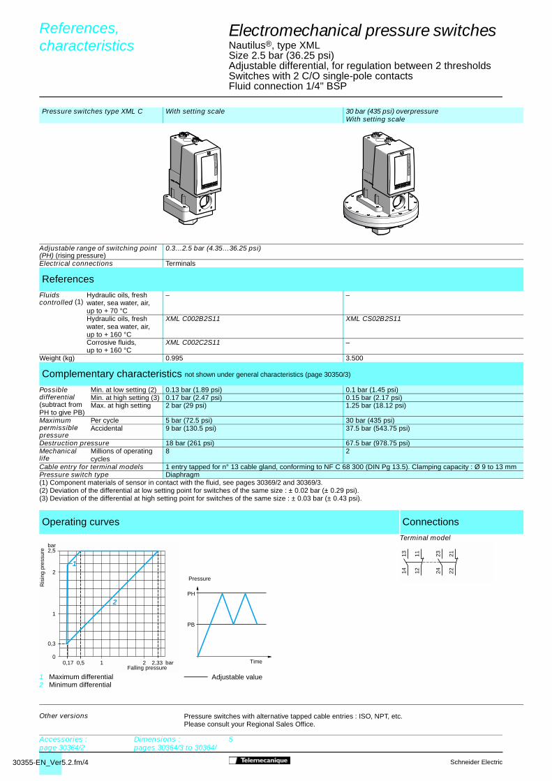
30355-EN_Ver5.2.fm/4 Schneider Electric
Electromechanical pressure switches 4
Nautilus®, type XMLSize 2.5 bar (36.25 psi)Adjustable differential, for regulation between 2 thresholdsSwitches with 2 C/O single-pole contactsFluid connection 1/4" BSP
Pressure switches type XML C With setting scale 30 bar (435 psi) overpressureWith setting scale
Adjustable range of switching point (PH) (rising pressure)
0.3…2.5 bar (4.35…36.25 psi)
Electrical connections Terminals
References
Fluids controlled (1)
Hydraulic oils, fresh water, sea water, air, up to + 70 °C
– –
Hydraulic oils, fresh water, sea water, air, up to + 160 °C
XML C002B2S11 XML CS02B2S11
Corrosive fluids,up to + 160 °C
XML C002C2S11 –
Weight (kg) 0.995 3.500
Complementary characteristics not shown under general characteristics (page 30350/3)
Possibledifferential(subtract fromPH to give PB)
Min. at low setting (2) 0.13 bar (1.89 psi) 0.1 bar (1.45 psi)Min. at high setting (3) 0.17 bar (2.47 psi) 0.15 bar (2.17 psi)Max. at high setting 2 bar (29 psi) 1.25 bar (18.12 psi)
Maximumpermissiblepressure
Per cycle 5 bar (72.5 psi) 30 bar (435 psi)Accidental 9 bar (130.5 psi) 37.5 bar (543.75 psi)
Destruction pressure 18 bar (261 psi) 67.5 bar (978.75 psi) Mechanical life
Millions of operating cycles
8 2
Cable entry for terminal models 1 entry tapped for n° 13 cable gland, conforming to NF C 68 300 (DIN Pg 13.5). Clamping capacity : Ø 9 to 13 mmPressure switch type Diaphragm(1) Component materials of sensor in contact with the fluid, see pages 30369/2 and 30369/3.(2) Deviation of the differential at low setting point for switches of the same size : ± 0.02 bar (± 0.29 psi).(3) Deviation of the differential at high setting point for switches of the same size : ± 0.03 bar (± 0.43 psi).
Operating curves Connections
1 Maximum differential2 Minimum differential
Adjustable value
Terminal model
Other versions Pressure switches with alternative tapped cable entries : ISO, NPT, etc.Please consult your Regional Sales Office.
Ris
ing
pres
sure
Falling pressure0,17 0,5
0
0,3
2 2,33
2
2,5
1
1
bar
bar
2
1
Pressure
Time
PH
PB
2324 22
211314 12
11
References, characteristics 0
Accessories :page 30364/2
Dimensions : pages 30364/3 to 30364/
5

30355-EN_Ver5.2.fm/5Schneider Electric
Electromechanical pressure switches 4
Nautilus®, type XMLSize 2.5 bar (36.25 psi)Dual stage, fixed differential, for detection at each thresholdSwitches with 2 C/O single-pole contactsFluid connection 1/4" BSP
Pressure switches type XML D Without setting scale
Adjustable range of each switching point (rising pressure)
2nd stage switchingpoint (PH2)
0.34…2.5 bar (4.93…36.25 psi)
1st stage switchingpoint (PH1)
0.2…2.36 bar (2.9…34.22 psi)
Spread between 2 stages (PH2 - PH1) 0.14…1.5 bar (2.03…21.75 psi)Electrical connections Terminal
References
Fluids controlled (1)
Hydraulic oils, fresh water, sea water, air, up to + 160 °C
XML D002B1S11
Corrosive fluids, up to + 160 °C
XML D002C1S11
Weight (kg) 1.015
Complementary characteristics not shown under general characteristics (page 30350/3)
Natural differential(subtract from PH1/PH2 to give PB1/PB2)
At low setting (2) 0.14 bar (2.03 psi)At high setting (3) 0.19 bar (2.76 psi)
Maximum permissible pressure
Per cycle 5 bar (72.5 psi)Accidental 9 bar (130.5 psi)
Destruction pressure 18 bar (261 psi) Mechanicallife
Millions of operating cycles
8
Cable entry for terminal models 1 entry tapped for n° 13 cable gland, conforming to NF C 68 300 (DIN Pg 13.5). Clamping capacity : Ø 9 to 13 mmPressure switch type Diaphragm(1) Component materials of sensor in contact with the fluid, see pages 30369/2 and 30369/3.(2) Deviation of the differential at low setting point for switches of the same size : ± 0.04 bar (± 0.58 psi).(3) Deviation of the differential at high setting point for switches of the same size : ± 0.07 bar (± 1.02 psi).
Operating curves Connections
High setting tripping points of contacts 1 and 2
1 Maximum differential 2 Minimum differential
Natural differential of contacts 1 and 2
EF Contact 1 (stage 1)GH Contact 2 (stage 2)
––––– Adjustable value– – – – Non adjustable value
Terminal model
Other versions Pressure switches with alternative tapped cable entries : ISO, NPT, etc.Please consult your Regional Sales Office.
0,20
0,34
2 2,36
2
2,5
1
1
1,69
bar
bar
2
1
PH1 setting (rising pressure)
PH
2 se
tting
(ris
ing
pres
sure
)
Falling pressure
Ris
ing
pres
sure
0,060
0,200,34
2,17 2,31
2
2,52,36
1
1
bar
bar HF
GE
Time
Pressure
PH2
PH1
PB1
PB2
Contact 2(stage 2)
Contact 1(stage 1)
2324 22
211314 12
11
References, characteristics 0
Accessories :page 30364/2
Dimensions : pages 30364/3 to 30364/
5

30356-EN_Ver5.3.fm/2 Schneider Electric
References, characteristics 0
Electromechanical pressure switches 4
Nautilus®, type XMLSize 4 bar (58 psi)Fixed differential, for detection of a single threshold Switches with 1 C/O single-pole contactFluid connection 1/4" BSP
Pressure switches type XML A With setting scale Without setting scale
Adjustable range of switchingpoint (PH) (rising pressure)
0.4…4 bar (5.8…58 psi)
Electrical connections Terminals DIN connector Terminals DIN connector
References
Fluids controlled (1)
Hydraulic oils, fresh water, sea water, air, up to + 70 °C
XML A004A2S11 XML A004A2C11 XML A004A1S11 XML A004A1C11
Hydraulic oils, fresh water, sea water, air, up to + 160 °C
XML A004B2S11 XML A004B2C11 XML A004B1S11 XML A004B1C11
Corrosive fluids, up to + 160 °C
XML A004C2S11 XML A004C2C11 XML A004C1S11 XML A004C1C11
Viscous products, up to + 160 °C
XML A004P2S11 XML A004P2C11 XML A004P1S11 XML A004P1C11
Weight (kg) 0.685 0.715 0.685 0.715
Complementary characteristics not shown under general characteristics (page 30350/3)
Natural differentialsubtract from PH to give PB
At low setting (2) 0,35 bar (5,07 psi)At high setting (2) 0,35 bar (5,07 psi)
Maximum permissible pressure
Per cycle 5 bar (72,5 psi)Accidental 9 bar (130,5 psi)
Destruction pressure 18 bar (261 psi)Mechanical life
Millions of operating cycles
8
Cable entry for terminal models 1 entry tapped for n° 13 cable gland, conforming to NF C 68 300 (DIN Pg 13.5). Clamping capacity : Ø 9 to 13 mmConnector type for connector models DIN 43650A, 4-pin male. For suitable female connector, see page 30364/2Pressure switch type Diaphragm(1) Component materials of sensor in contact with the fluid, see pages 30369/2 and 30369/3.(2) Deviation of the differential at high and low setting points for switches of the same size : ± 0.03 bar (± 0.43 psi).
Operating curves Connections
Terminal model
Connector modelSwitch connector pin view
1 � 11 and 132 � 123 � 14
Other versions Pressure switches with alternative tapped cable entries : ISO, NPT, etc.Please consult your Regional Sales Office.
0,05 bar
bar
01 2 4
1
2
3
0,4
3 3,65
4
Pressure
Time
PH
PB
Ris
ing
pres
sure
Falling pressure Adjustable valueNon adjustable value
1314 12
11
321
Accessories :page 30364/2
Dimensions :pages 30364/3 to 30364/5

30356-EN_Ver5.3.fm/3Schneider Electric
Accessories :page 30364/2
Dimensions :pages 30364/3 to 30364/5
Electromechanical pressure switches 4
Nautilus®, type XMLSize 4 bar (58 psi)Adjustable differential, for regulation between 2 thresholdsSwitches with 1 C/O single-pole contactFluid connection 1/4" BSP
Pressure switches type XML B With setting scale Without setting scale 30 bar (435 psi) overpressureWith setting scale
Adjustable range of switchingpoint (PH) (rising pressure)
0.25…4 bar (3.62…58 psi)
Electrical connections Terminals DIN connector Terminals DIN connector Terminals
References
Fluids controlled (1)
Hydraulic oils, fresh water, sea water, air, up to + 70 °
XML B004A2S11 XML B004A2C11 XML B004A1S11 XML B004A1C11 –
Hydraulic oils, fresh water, sea water, air, up to + 160 °C
XML B004B2S11 XML B004B2C11 XML B004B1S11 XML B004B1C11 XML BS04A2S11
Corrosive fluids, up to + 160 °C
XML B004C2S11 XML B004C2C11 XML B004C1S11 XML B004C1C11 –
Weight (kg) 1.015 1.030 1.015 1.030 3.500
Complementary characteristics not shown under general characteristics (page 30350/3)
Possible differential subtract from PH to give PB
Min. at low setting (2) 0.2 bar (2.9 psi) 0.15 bar (2.18 psi)Min. at high setting (3) 0.25 bar (3.62 psi) 0.34 bar (4.93 psi)Max. at high setting 2.4 bar (34.8 psi) 2.46 bar (35.67 psi)
Maximum permissible pressure
Per cycle 5 bar (72.5 psi) 30 bar (435 psi)Accidental 9 bar (130.5 psi) 37.5 bar (543.75 psi)
Destruction pressure 18 bar (261 psi) 67.5 bar (978.75 psi)Mechanical life
Millions of operating cycles
8 2
Cable entry for terminal models 1 entry tapped for n° 13 cable gland, conforming to NF C 68 300 (DIN Pg 13.5). Clamping capacity : Ø 9 to 13 mmConnector type for connector models DIN 43650A, 4-pin male. For suitable female connector, see page 30364/2Pressure switch type Diaphragm(1) Component materials of sensor in contact with the fluid, see pages 30369/2 and 30369/3.(2) Deviation of the differential at low setting point for switches of the same size : ± 0.01 bar (± 0.14 psi).(3) Deviation of the differential at high setting point for switches of the same size : - 0.03 bar, + 0.05 bar (- 0.43 psi, + 0.72 psi).
Operating curves Connections
Terminal model
Connector modelSwitch connector pin view
1 � 11 and 132 � 123 � 14
Other versions Pressure switches with alternative tapped cable entries : ISO, NPT, etc.Please consult your Regional Sales Office.
0,05 bar
bar
01 21,6
1
2
3
0,25
3 3,75
4
1 2
Pressure
Time
Ris
ing
pres
sure
Falling pressure
Adjustable value1 Maximum differential2 Minimum differential
PH
PB
1314 12
11
321
References, characteristics 0

30356-EN_Ver5.3.fm/4 Schneider Electric
References, characteristics 0
Electromechanical pressure switches 4
Nautilus®, type XMLSize 4 bar (58 psi)Adjustable differential, for regulation between 2 thresholdsSwitches with 2 C/O single-pole contactsFluid connection 1/4" BSP
Pressure switches type XML C With setting scale 30 bar (435 psi) overpressureWith setting scale
Adjustable range of switching point (PH) (rising pressure)
0.3…4 bar (4.35…58 psi)
Electrical connections Terminals
References
Fluids controlled (1)
Hydraulic oils, fresh water, sea water, air, up to + 70 °C
– –
Hydraulic oils, fresh water, sea water, air, up to + 160 °C
XML C004B2S11 XML CS04B2S11
Corrosive fluids, up to + 160 °C
XML C004C2S11 –
Weight (kg) 0.685 3.500
Complementary characteristics not shown under general characteristics (page 30350/3)
Possible differentialsubtract from PH to give PB
Min. at low setting (2) 0.15 bar (2.18 psi) 0.1 bar (1.45 psi)Min. at high setting (2) 0.17 bar (2.47 psi) 0.25 bar (3.62 psi)Max. at high setting 2.5 bar (36.25 psi) 2.20 bar (31.9 psi)
Maximum permissible pressure
Per cycle 5 bar (72.5 psi) 30 bar (435 psi)Accidental 9 bar (130.5 psi) 37.5 bar (543.75 psi)
Destruction pressure 18 bar (261 psi) 67.5 bar (978.75 psi)Mechanical life
Millions of operating cycles
8 2
Cable entry for terminal models 1 entry tapped for n° 13 cable gland, conforming to NF C 68 300 (DIN Pg 13.5)Clamping capacity : Ø 9 to 13 mm
Pressure switch type Diaphragm(1) Component materials of sensor in contact with the fluid, see pages 30369/2 and 30369/3.(2) Deviation of the differential at high and low setting points for switches of the same size : ± 0.02 bar (± 0.29 psi).
Operating curves Connections
Terminal model
Other versions Pressure switches with alternative tapped cable entries : ISO, NPT, etc.Please consult your Regional Sales Office.
Pressure
Time
Ris
ing
pres
sure
Falling pressure
Adjustable value1 Maximum differential2 Minimum differential
0,15 bar
bar
01 21,5
1
2
3
0,3
3 3,83
4
1
2PH
PB
2324 22
211314 12
11
Accessories :page 30364/2
Dimensions :pages 30364/3 to 30364/5
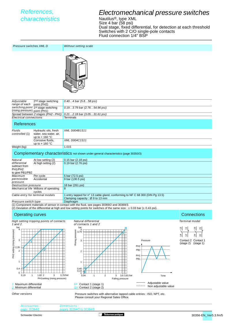
30356-EN_Ver5.3.fm/5Schneider Electric
Electromechanical pressure switches 4
Nautilus®, type XMLSize 4 bar (58 psi)Dual stage, fixed differential, for detection at each thresholdSwitches with 2 C/O single-pole contactsFluid connection 1/4" BSP
Pressure switches XML D Without setting scale
Adjustable range of each switching point (rising pressure)
2nd stage switching point (PH2)
0.40…4 bar (5.8…58 psi)
1st stage switching point (PH1)
0.19…3.79 bar (2.76…54.96 psi)
Spread between 2 stages (PH2 - PH1) 0.21…2.18 bar (3.05…31.61 psi)Electrical connections Terminals
References
Fluids controlled (1)
Hydraulic oils, fresh water, sea water, air, up to + 160 °C
XML D004B1S11
Corrosive fluids, up to + 160 °C
XML D004C1S11
Weight (kg) 1.015
Complementary characteristics not shown under general characteristics (page 30350/3)
Natural differential subtract from PH1/PH2 to give PB1/PB2
At low setting (2) 0.15 bar (2.18 psi)At high setting (2) 0.19 bar (2.76 psi)
Maximum permissible pressure
Per cycle 5 bar (72.5 psi)Accidental 9 bar (130.5 psi)
Destruction pressure 18 bar (261 psi) Mechanical life Millions of operating
cycles8
Cable entry for terminal models 1 entry tapped for n° 13 cable gland, conforming to NF C 68 300 (DIN Pg 13.5)Clamping capacity : Ø 9 to 13 mm
Pressure switch type Diaphragm(1) Component materials of sensor in contact with the fluid, see pages 30369/2 and 30369/3.(2) Deviation of the differential at high and low setting points for switches of the same size : ± 0.03 bar (± 0.43 psi).
Operating curves Connections
High setting tripping points of contacts1 and 2
1 Maximum differential 2 Minimum differential
Natural differential of contacts 1 and 2
EF Contact 1 (stage 1)GH Contact 2 (stage 2)
Terminal model
Other versions Pressure switches with alternative tapped cable entries : ISO, NPT, etc.Please consult your Regional Sales Office.
0,19 bar
bar
01 21,82
1
2
2,35
3
0,4
3 3,79
4
1
2
PH1setting (rising pressure)
PH
2 se
tting
(ris
ing
pres
sure
)
0,04 bar
bar
01 2
1
2
3
0,190,40
3 3,6 3,81
43,79
E
G
H
F
Falling pressure
Ris
ing
pres
sure
PH2
PH1
PB1
PB2
Time
Pressure
Adjustable valueNon adjustable value
Contact 2(stage 2)
Contact 1(stage 1)
2324 22
211314 12
11
References, characteristics 0
Accessories :page 30364/2
Dimensions :pages 30364/3 to 30364/5

30357-EN_Ver5.3.fm/2 Schneider Electric
References, 0
characteristics 0
Electromechanical pressure switches 4
Nautilus®, type XMLSize 10 bar (145 psi)Fixed differential, for detection of a single thresholdSwitches with 1 C/O single-pole contactFluid connection 1/4" BSP
Pressure switches type XML A With setting scale Without setting scale
Adjustable range of switching point (PH) (rising pressure)
0.6…10 bar (8.7…145 psi)
Electrical connections Terminals DIN connector Terminals DIN connector
References
Fluids controlled (1)
Hydraulic oils, fresh water, sea water, air, up to + 70 °C
XML A010A2S11 XML A010A2C11 XML A010A1S11 XML A010A1C11
Hydraulic oils, fresh water, sea water, air, up to + 160 °C
XML A010B2S11 XML A010B2C11 XML A010B1S11 XML A010B1C11
Corrosive fluids, up to + 160 °C
XML A010C2S11 XML A010C2C11 XML A010C1S11 XML A010C1C11
Viscous products, up to + 160 °C
XML A010P2S11 XML A010P2C11 XML A010P1S11 XML A010P1C11
Weight (kg) 0.685 0.715 0.685 0.715
Complementary characteristics not shown under general characteristics (page 30350/3)
Natural differentialsubtract from PH to give PB
At low setting (2) 0.5 bar (7.25 psi)At high setting (2) 0.5 bar (7.25 psi)
Maximum permissible pressure
Per cycle 12.5 bar (181.25 psi)Accidental 22.5 bar (326.25 psi)
Destruction pressure 45 bar (652.5 psi)Mechanical life
Milions of operating cycles
5
Cable entry for terminal models 1 entry tapped for n° 13 cable gland, conforming to NF C 68-300 (DIN Pg 13.5). Clamping capacity : Ø 9 to 13 mmConnector type for connector models DIN 43650A, 4-pin male. For suitable female connector, see page 30364/2Pressure switch type Diaphragm(1) Component materials of sensor in contact with the fluid, see pages 30369/2 and 30369/3. (2) Deviation of the differential at high and low setting points for switches of the same size : ± 0.05 bar (± 0.72 psi).
Operating curves Connections
Terminal model
Connector model Switch connector pin view
1 � 11 and 132 � 123 � 14
Other versions Pressure switches with alternative tapped cable entries : ISO, NPT, etc.Please consult your Regional Sales Office.
bar
bar
0
8
6
4
2
10,6
10
9,586420,1
Pressure
Time
Ris
ing
pres
sure
Falling pressure
Adjustable valueNon adjustable value
PH
PB
1314 12
11
321
Accessories :page 30364/2
Dimensions :pages 30364/3 to 30364/5

30357-EN_Ver5.3.fm/3Schneider Electric
References, characteristics 0
Electromechanical pressure switches 4
Nautilus®, type XMLSize 10 bar (145 psi)Adjustable differential, for regulation between 2 thresholdsSwitches with 1 C/O single-pole contactFluid connection 1/4" BSP
Pressure switches type XML B With setting scale Without setting scale 30 bar (435 psi) overpressureWith setting scale
Adjustable range of switchingpoint (PH) (rising pressure)
0.7…10 bar (10.15…145 psi)
Electrical connections Terminals DIN connector Terminals DIN connector Terminals
References
Fluids controlled (1)
Hydraulic oils, fresh water, sea water, air, up to + 70 °C
XML B010A2S11 XML B010A2C11 XML B010A1S11 XML B010A1C11 XML BS10A2S11
Hydraulic oils, fresh water, sea water, air, up to + 160 °C
XML B010B2S11 XML B010B2C11 XML B010B1S11 XML B010B1C11 –
Corrosive fluids, up to + 160 °C
XML B010C2S11 XML B010C2C11 XML B010C1S11 XML B010C1C11 –
Viscous products, up to + 160 °C
XML B010P2S11 XML B010P2C11 XML B010P1S11 XML B010P1C11 –
Weight (kg) 0.705 0.735 0.705 0.735 3.500
Complementary characteristics not shown under general characteristics (page 30350/3)
Possible differentialsubtract from PH to give PB
Min. at low setting (2) 0.57 bar (8.26 psi) 0.45 bar (6.52 psi)Min. at high setting (3) 0.85 bar (12.32 psi) 0.85 bar (12.32 psi)Max. at high setting 7.5 bar (108.75 psi) 6.25 bar (90.62 psi)
Maximum permissible pressure
Per cycle 12.5 bar (181.25 psi) 30 bar (435 psi)Accidental 22.5 bar (326.25 psi) 37.5 bar (543.75 psi)
Destruction pressure 45 bar (652.5 psi) 67.5 bar (978.75 psi)Mechanical life
Millions of operating cycles
5 2
Cable entry for terminal models 1 entry tapped for n° 13 cable gland, conforming to NF C 68-300 (DIN Pg 13.5). Clamping capacity : Ø 9 to 13 mmConnector type for connector models DIN 43650A, 4-pin male. For suitable female connector, see page 30364/2Pressure switch type Diaphragm(1) Component materials of sensor in contact with the fluid, see pages 30369/2 and 30369/3.(2) Deviation of the differential at low setting point for switches of the same size : ± 0.05 bar (± 0.72 psi).(3) Deviation of the differential at high setting point for switches of the same size : - 0.1 bar, + 0.15 bar (- 1.45 psi, + 2.17 psi).
Operating curves Connections
1 Maximum differential2 Minimum differential
Adjustable value
Terminal model
Connector modelSwitch connector pin view
1 � 11 and 132 � 123 � 14
Other versions Pressure switches with alternative tapped cable entries : ISO, NPT, etc.Please consult your Regional Sales Office.
bar
bar
0
8
6
4
2
0,7
10
9,158642,50,13
2
1
Ris
ing
pres
sure
Falling pressure
Pressure
Time
PH
PB
1314 12
11
321
Accessories :page 30364/2
Dimensions :pages 30364/3 to 30364/5

30357-EN_Ver5.3.fm/4 Schneider Electric
References, 0
characteristics 0
Electromechanical pressure switches 4
Nautilus®, type XMLSize 10 bar (145 psi)Adjustable differential, for regulation between 2 thresholdsSwitches with 2 C/O single-pole contactsFluid connection 1/4" BSP
Pressure switches type XML C With setting scale 30 bar (435 psi) overpressureWith setting scale
Adjustable range of switchingpoint (PH) (rising pressure)
0.7…10 bar (10.15…145 psi)
Electrical connections Terminals
References
Fluids controlled (1)
Hydraulic oils, fresh water, sea water, air, up to + 70 °C
– XML CS10A2S11
Hydraulic oils, fresh water, sea water, air, up to + 160 °C
XML C010B2S11 –
Corrosive fluids, up to + 160 °C
XML C010C2S11 –
Weight (kg) 0.685 3.500
Complementary characteristics not shown under general characteristics (page 30350/3)
Possible differentialsubtract from PH to give PB
Min. at low setting (2) 0.45 bar (6.53 psi) 0.25 bar (3.62 psi)Min. at high setting (3) 0.70 bar (10.15 psi) 0.65 bar (9.42 psi)Max. at high setting 8 bar (116 psi) 5.6 bar (81.2 psi)
Maximum permissible pressure
Per cycle 12.5 bar (181.25 psi) 30 bar (435 psi)Accidental 22.5 bar (326.25 psi) 37.5 bar (543.75 psi)
Destruction pressure 45 bar (652.5 psi) 67.5 bar (978.75 psi)Mechanical life
Millions of operating cycles
5 2
Cable entry for terminal models 1 entry tapped for n° 13 cable gland, conforming to NF C 68-300 (DIN Pg 13.5). Clamping capacity : Ø 9 to 13 mmPressure switch type Diaphragm(1) Component materials of sensor in contact with the fluid, see pages 30369/2 and 30369/3.(2) Deviation of the differential at low setting point for switches of the same size : ± 0.05 bar (± 0.72 psi).(3) Deviation of the differential at high setting point for switches of the same size : ± 0.1 bar (± 1.45 psi).
Operating curves Connections
1 Maximum differential 2 Minimum differential Adjustable value
Terminal model
Other versions Pressure switches with alternative tapped cable entries : ISO, NPT, etc.Please consult your Regional Sales Office.
bar
bar
0
6
4
2
0,7
10
9,386420,25
2
1
Ris
ing
pres
sure
Falling pressure
Pressure
Time
PH
PB
2324 22
211314 12
11
Accessories :page 30364/2
Dimensions :pages 30364/3 to 30364/5

30357-EN_Ver5.3.fm/5Schneider Electric
Electromechanical pressure switches 4
Nautilus®, type XMLSize 10 bar (145 psi)Dual stage, fixed differential, for detection at each thresholdSwitches with 2 C/O single-pole contactsFluid connection 1/4" BSP
Pressure switches type XML D Without setting scale
Adjustable range of each switching point (rising pressure)
2nd stage switching point (PH2)
1.2…10 bar (17.4…145 psi)
1st stage switchingpoint (PH1)
0.52…9.32 bar (7.54…135.14 psi)
Spread between 2 stages (PH2 - PH1) 0.68…5.8 bar (9.86…84.1 psi)Electrical connections Terminals
References
Fluids controlled (1)
Hydraulic oils, fresh water, sea water, air, up to + 160 °C
XML D010B1S11
Corrosive fluids, up to + 160 °C
XML D010C1S11
Weight (kg) 0.705
Complementary characteristics not shown under general characteristics (page 30350/3)
Natural differentialsubtract from PH1/PH2 to give PB1/PB2
At low setting (2) 0.45 bar (6.53 psi)At high setting (3) 0.6 bar (8.7 psi)
Maximum permissible pressure
Per cycle 12.5 bar (181.25 psi)Accidental 22.5 bar (326.25 psi)
Destruction pressure 45 bar (652.5 psi)Mechanicallife
Millions of operating cycles
5
Cable entry for terminal models 1 entry tapped for n° 13 cable gland, conforming to NF C 68-300 (DIN Pg 13.5). Clamping capacity : Ø 9 to 13 mmPressure switch type Diaphragm(1) Component materials of sensor in contact with the fluid, see pages 30369/2 and 30369/3.(2) Deviation of the differential at low setting point for switches of the same size : ± 0.05 bar (± 0.72 psi).(3) Deviation of the differential at high setting point for switches of the same size : ± 0.1 bar (- 1.45 psi).
Operating curves Connections
High setting tripping points of contacts 1 and 2
1 Maximum differential 2 Minimum differential
Natural differential ofcontacts 1 and 2
EF Contact 1 (stage 1)GH Contact 2 (stage 2)
Terminal model
Other versions Pressure switches with alternative tapped cable entries : ISO, NPT, etc.Please consult your Regional Sales Office.
bar
bar
0
8
66,34
4
2
1,2
10
9,32864,220,52
2
1
PH1 setting (rising pressure)
PH
2 se
tting
(ris
ing
pres
sure
)
bar
bar
0
8
9,32
6
4
2
0,521,2
10
9,48,726420,07 0,75
H
F
G
E
Falling pressure
Ris
ing
pres
sure
Time
Pressure
PH2
PH1
PB1
PB2
Adjustable valueNon adjustable value
Contact 2(stage 2)
Contact 1(stage 1)
2324 22
211314 12
11
References, 0
characteristics 0
Accessories :page 30364/2
Dimensions :pages 30364/3 to 30364/5

30358-EN_Ver5.2.fm/2 Schneider Electric
Pressure switches type XML A With setting scale Without setting scale
Adjustable range of switchingpoint (PH) (rising pressure)
0.7…20 bar (10.2…290 psi)
Electrical connections Terminals DIN connector Terminals DIN connector
References
Fluids controlled (1)
Hydraulic oils, fresh water, sea water, air, up to + 70 °C
XML A020A2S11 XML A020A2C11 XML A020A1S11 XML A020A1C11
Hydraulic oils, fresh water, sea water, air, up to + 160 °C
XML A020B2S11 XML A020B2C11 XML A020B1S11 XML A020B1C11
Corrosive fluids, up to + 160 °C
XML A020C2S11 XML A020C2C11 XML A020C1S11 XML A020C1C11
Viscous products, up to + 160 °C
XML A020P2S11 XML A020P2C11 XML A020P1S11 XML A020P1C11
Weight (kg) 0.685 0.715 0.685 0.715
Complementary characteristics not shown under general characteristics (page 30350/3)
Natural differentialsubtract from PH to give PB
At low setting (2) 0.4 bar (5.8 psi)At high setting (2) 1 bar (14.5 psi)
Maximum permissible pressure
Per cycle 25 bar (362.5 psi)Accidental 45 bar (652.5 psi)
Destruction pressure 90 bar (1305 psi)Mechanical life
Millions of operating cycles
5
Cable entry for terminal models 1 entry tapped for n° 13 cable gland, conforming to NF C 68-300 (DIN Pg 13.5). Clamping capacity : Ø 9 to 13 mmConnector type for connector models DIN 43650A, 4-pin male. For suitable female connector, see page 30364/2Pressure switch type Diaphragm(1) Component materials of sensor in contact with the fluid, see pages 30369/2 and 30369/3.(2) Deviation of the differential at high and low setting points for switches of the same size : ± 0.1 bar (± 1.45 psi).
Operating curves Connections
Terminal model
Connector model Switch connector pin view
1 � 11 and 132 � 123 � 14
Other versions Pressure switches with alternative tapped cable entries : ISO, NPT, etc.Please consult your Regional Sales Office.
0,3 bar
bar
05 10
5
10
15
0,7
15 19,3
20
Pressure
Time
Ris
ing
pres
sure
Falling pressure
Adjustable valueNon adjustable value
PH
PB
1314 12
11
321
Electromechanical pressure switches 4
Nautilus®, type XMLSize 20 bar (290 psi)Fixed differential, for detection of a single threshold Switches with 1 C/O single-pole contactFluid connection 1/4" BSP
References, 0
characteristics 0
Accessories :page 30364/2
Dimensions :pages 30364/3 to 30364/5

30358-EN_Ver5.2.fm/3Schneider Electric
Pressure switches type XML B With setting scale Without setting scale 30 bar (435 psi) overpressureWith setting scale
Adjustable range of switchingpoint (PH) (rising pressure)
1.3…20 bar (18.9…290 psi)
Electrical connections Terminals DIN connector Terminals DIN connector Terminals
References
Fluids controlled (1)
Hydraulic oils, fresh water, sea water, air, up to + 70 °C
XML B020A2S11 XML B020A2C11 XML B020A1S11 XML B020A1C11 XML BS20A2S11
Hydraulic oils, fresh water, sea water, air, up to + 160 °C
XML B020B2S11 XML B020B2C11 XML B020B1S11 XML B020B1C11 –
Corrosive fluids, up to + 160 °C
XML B020C2S11 XML B020C2C11 XML B020C1S11 XML B020C1C11 –
Viscous products, up to + 160 °C
XML B020P2S11 XML B020P2C11 XML B020P1S11 XML B020P1C11 –
Weight (kg) 0.705 0.735 0.705 0.735 3.500
Complementary characteristics not shown under general characteristics (page 30350/3)
Possible differentialsubtract from PH to give PB
Min. at low setting (2) 1 bar (14.5 psi) 0.95 bar (13.78 psi)Min. at high setting (2) 1.60 bar (23.20 psi) 1.45 bar (21.03 psi)Max. at high setting 11 bar (159.5 psi) 12.6 bar (182.7 psi)
Maximum permissible pressure
Per cycle 25 bar (362.5 psi) 30 bar (435 psi)Accidental 45 bar (652.5 psi) 37.5 bar (543.75 psi)
Destruction pressure 90 bar (1305 psi) 67.5 bar (978.75 psi)Mechanical life
Millions of operating cycles
5 2
Cable entry for terminal models 1 entry tapped for n° 13 cable gland, conforming to NF C 68-300 (DIN Pg 13.5). Clamping capacity : Ø 9 to 13 mmConnector type for connector models DIN 43650A, 4-pin male. For suitable female connector, see page 30364/2Pressure switch type Diaphragm(1) Component materials of sensor in contact with the fluid, see pages 30369/2 and 30369/3.(2) Deviation of the differential at high and low setting points for switches of the same size : ± 0.25 bar (± 3.63 psi).
Operating curves Connections
1 Maximum differential2 Minimum differential
Adjustable value
Terminal model
Connector modelSwitch connector pin view
1 � 11 and 132 � 123 � 14
Other versions Pressure switches with alternative tapped cable entries : ISO, NPT, etc.Please consult your Regional Sales Office.
0,3 bar
bar
05 109
5
10
15
1,3
15 18,4
20
1 2
Ris
ing
pres
sure
Falling pressure
Pressure
Time
PH
PB
1314 12
11
321
Electromechanical pressure switches 4
Nautilus®, type XMLSize 20 bar (290 psi)Adjustable differential, for regulation between 2 thresholdsSwitches with 1 C/O single-pole contactFluid connection 1/4" BSP
References, 0
characteristics 0
Accessories :page 30364/2
Dimensions :pages 30364/3 to 30364/5

30358-EN_Ver5.2.fm/4 Schneider Electric
Electromechanical pressure switches 4
Nautilus®, type XMLSize 20 bar (290 psi)Adjustable differential, for regulation between 2 thresholdsSwitches with 2 C/O single-pole contactsFluid connection 1/4" BSP
Pressure switches type XML C With setting scale 30 bar (435 psi) overpressureWith setting scale
Adjustable range of switchingpoint (PH) (rising pressure)
1.3…20 bar (18.85…290 psi)
Electrical connections Terminals
References
Fluids controlled (1)
Hydraulic oils, fresh water, sea water, air, up to + 70 °C
– XML CS20A2S11
Hydraulic oils, fresh water, sea water, air, up to + 160 °C
XML C020B2S11 –
Corrosive fluids, up to + 160 °C
XML C020C2S11 –
Weight (kg) 0.685 3.500
Complementary characteristics not shown under general characteristics (page 30350/3)
Possible differential subtract from PH to give PB
Min. at low setting (2) 0.7 bar (10.15 psi) 0.7 bar (10.15 psi)Min. at high setting (2) 1 bar (14.5 psi) 1.15 bar (16.67 psi)Max. at high setting 11 bar (159.5 psi) 11.70 bar (169.6 psi)
Maximum permissible pressure
Per cycle 25 bar (362.5 psi) 30 bar (435 psi)Accidental 45 bar (652.5 psi) 37.5 bar (543.75 psi)
Destruction pressure 90 bar (1305 psi) 67.5 bar (978.75 psi) Mechanical life
Millions of operating cycles
5 2
Cable entry for terminal models 1 entry tapped for n° 13 cable gland, conforming to NF C 68-300 (DIN Pg 13.5). Clamping capacity : Ø 9 to 13 mmPressure switch type Diaphragm(1) Component materials of sensor in contact with the fluid, see pages 30369/2 and 30369/3.(2) Deviation of the differential at high and low setting points for switches of the same size : ± 0.2 bar (± 2.9 psi).
Operating curves Connections
1 Maximum differential2 Minimum differential
Adjustable value
Terminal model
Other versions Pressure switches with alternative tapped cable entries : ISO, NPT, etc.Please consult your Regional Sales Office.
0,6 bar
bar
05 9 10
5
15
1,3
15 19
20
1 2
10
Ris
ing
pres
sure
Falling pressure
Pressure
Time
PH
PB
2324 22
211314 12
11
References, 0
characteristics 0
Accessories :page 30364/2
Dimensions :pages 30364/3 to 30364/5

30358-EN_Ver5.2.fm/5Schneider Electric
Pressure switches type XML D Without setting scale
Adjustment range of each switching point (rising pressure)
2nd stage switching point (PH2)
2.14…20 bar (31.03…290 psi)
1st stage switching point (PH1)
0.9…18.76 bar (13.05…272.02 psi)
Spread between 2 stages (PH2 - PH1) 1.24…9.55 bar (17.98…138.48 psi)Electrical connections Terminals
References
Fluids controlled (1)
Hydraulic oils, fresh water, sea water, air, up to + 160 °C
XML D020B1S11
Corrosive fluids, up to + 160 °C
XML D020C1S11
Weight (kg) 0.705
Complementary characteristics not shown under general characteristics (page 30350/3)
Natural At low setting (2) 0.7 bar (10.15 psi)differential At high setting (3) 1.3 bar (18.85 psi)subtract from PH1/PH2 to givePB1/PB2Maximum permissible pressure
Per cycle 25 bar (362.5 psi)Accidental 45 bar (652.5 psi)
Destruction pressure 90 bar (1305 psi) Mechanical life
Millions of operating cycles
5
Cable entry for terminal models 1 entry tapped for n° 13 cable gland, conforming to NF C 68-300 (DIN Pg 13.5). Clamping capacity : Ø 9 to 13 mmPressure switch type Diaphragm(1) Component materials of sensor in contact with the fluid, see pages 30369/2 and 30369/3.(2) Deviation of the differential at low setting point for switches of the same size : ± 0.15 bar (± 2.18 psi).(3) Deviation of the differential at high setting point for switches of the same size : ± 0.1 bar (± 1.45 psi).
Operating curves Connections
High setting tripping points ofcontacts 1 and 2
1 Maximum differential 2 Minimum differential
Natural differential of contacts 1 and 2
EF Contact 1 (stage 1)GH Contact 2 (stage 2)
––––– Adjustable value– – – – Non adjustable value
Terminal model
Other versions Pressure switches with alternative tapped cable entries : ISO, NPT, etc.Please consult your Regional Sales Office.
0,9 bar
bar
05 10,45
5
10,6
15
2,14
15 18,76
20
1 2
PH1 setting (rising pressure)
PH
2 se
tting
(ris
ing
pres
sure
)
0,2 1,44 bar
bar
05 10
5
10
15
18,76
0,92,14
15 17,46 18,7
20
E
F
H
G
Falling pressure
Ris
ing
pres
sure
Time
Pressure
PH2
PH1
PB1
PB2
Contact 2(stage 2)
Contact 1(stage 1)
2324 22
211314 12
11
Electromechanical pressure switches 4
Nautilus®, type XMLSize 20 bar (290 psi)Dual stage, fixed differential, for detection at each thresholdSwitches with 2 C/O single-pole contactsFluid connection 1/4" BSP
References, 0
characteristics 0
Accessories :page 30364/2
Dimensions :pages 30364/3 to 30364/5
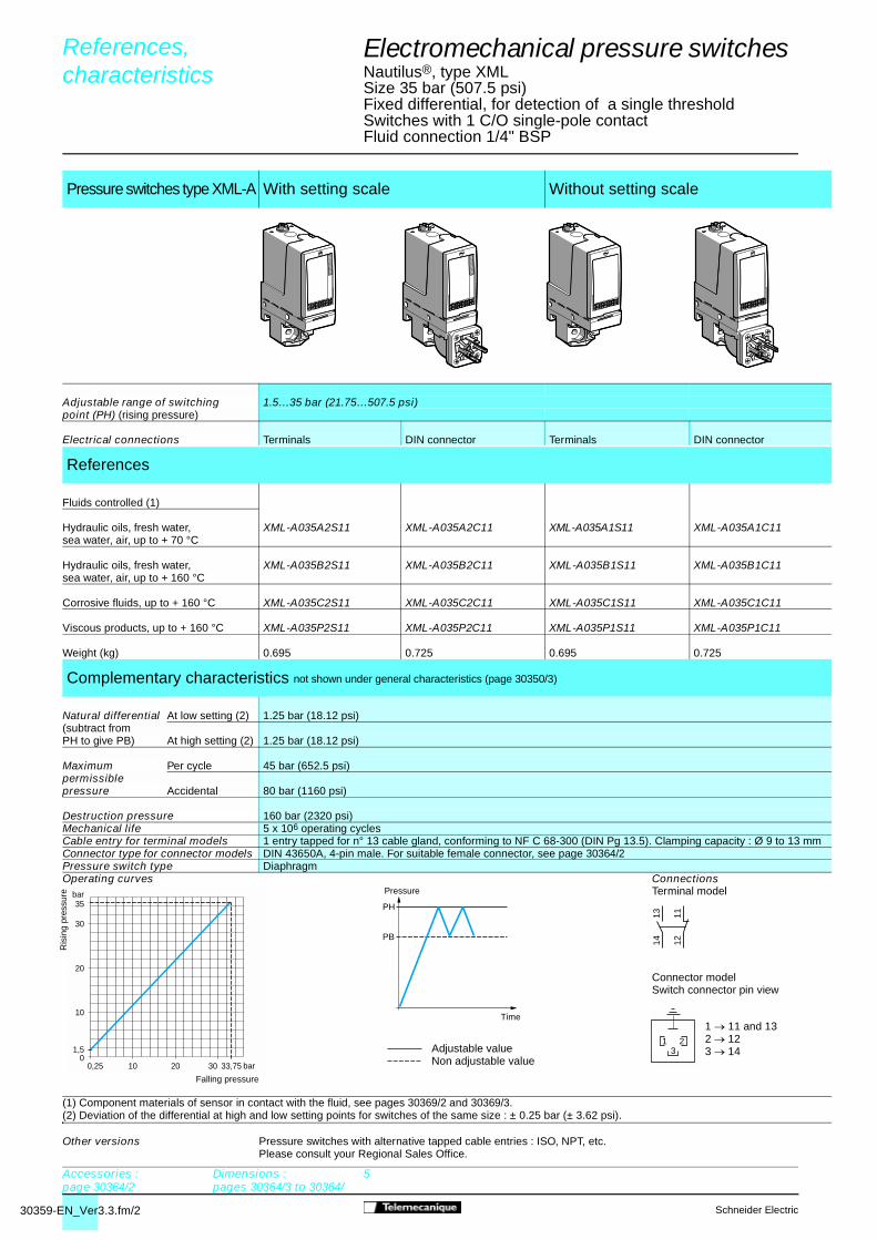
30359-EN_Ver3.3.fm/2 Schneider Electric
0,25 bar
bar
010 20 30 33,75
10
20
30
1,5
35
1314 12
11
321
PH
PB
Electromechanical pressure switches 4
Nautilus®, type XMLSize 35 bar (507.5 psi)Fixed differential, for detection of a single threshold Switches with 1 C/O single-pole contactFluid connection 1/4" BSP
(1) Component materials of sensor in contact with the fluid, see pages 30369/2 and 30369/3.(2) Deviation of the differential at high and low setting points for switches of the same size : ± 0.25 bar (± 3.62 psi).
Pressure switches type XML-A With setting scale Without setting scale
Adjustable range of switching 1.5…35 bar (21.75…507.5 psi)point (PH) (rising pressure)
Electrical connections Terminals DIN connector Terminals DIN connector
References
Fluids controlled (1)
Hydraulic oils, fresh water, XML-A035A2S11 XML-A035A2C11 XML-A035A1S11 XML-A035A1C11sea water, air, up to + 70 °C
Hydraulic oils, fresh water, XML-A035B2S11 XML-A035B2C11 XML-A035B1S11 XML-A035B1C11sea water, air, up to + 160 °C
Corrosive fluids, up to + 160 °C XML-A035C2S11 XML-A035C2C11 XML-A035C1S11 XML-A035C1C11
Viscous products, up to + 160 °C XML-A035P2S11 XML-A035P2C11 XML-A035P1S11 XML-A035P1C11
Weight (kg) 0.695 0.725 0.695 0.725
Complementary characteristics not shown under general characteristics (page 30350/3)
Natural differential At low setting (2) 1.25 bar (18.12 psi)(subtract fromPH to give PB) At high setting (2) 1.25 bar (18.12 psi)
Maximum Per cycle 45 bar (652.5 psi)permissiblepressure Accidental 80 bar (1160 psi)
Destruction pressure 160 bar (2320 psi)Mechanical life 5 x 10⁶ operating cyclesCable entry for terminal models 1 entry tapped for n° 13 cable gland, conforming to NF C 68-300 (DIN Pg 13.5). Clamping capacity : Ø 9 to 13 mmConnector type for connector models DIN 43650A, 4-pin male. For suitable female connector, see page 30364/2Pressure switch type DiaphragmOperating curves Connections
Terminal model
Connector modelSwitch connector pin view
Other versions Pressure switches with alternative tapped cable entries : ISO, NPT, etc.Please consult your Regional Sales Office.
References, characteristics 0
Falling pressure
Adjustable valueNon adjustable value
Pressure
Time1 � 11 and 132 � 123 � 14
Accessories :page 30364/2
Dimensions :pages 30364/3 to 30364/
5
Ris
ing
pres
sure

30359-EN_Ver3.3.fm/3Schneider Electric
1314 12
11
321
1,8 bar
bar
010 15 20 32,45
10
20
30
3,5
35
1 2Ris
ing
pres
sure
Falling pressure
PH
PB
Electromechanical pressure switches 4
Nautilus®, type XMLSize 35 bar (507.5 psi)Adjustable differential, for regulation between 2 thresholdsSwitches with 1 C/O single-pole contactFluid connection 1/4" BSP
(1) Component materials of sensor in contact with the fluid, see pages 30369/2 and 30369/3.(2) Deviation of the differential at high and low setting points for switches of the same size : - 0.5 bar, + 0.7 bar (- 7.25 psi, + 10.15 psi).
Pressure switches type XML-B With setting scale Without setting scale
Adjustable range of switching 3.5…35 bar (50.75…507.5 psi)point (PH) (rising pressure)
Electrical connections Terminals DIN connector Terminals DIN connector
References
Fluids controlled (1)
Hydraulic oils, fresh water, XML-B035A2S11 XML-B035A2C11 XML-B035A1S11 XML-B035A1C11sea water, air, up to + 70 °C
Hydraulic oils, fresh water, XML-B035B2S11 XML-B035B2C11 XML-B035B1S11 XML-B035B1C11sea water, air, up to + 160 °C
Corrosive fluids, up to + 160 °C XML-B035C2S11 XML-B035C2C11 XML-B035C1S11 XML-B035C1C11
Viscous products, up to + 160 °C XML-B035P2S11 XML-B035P2C11 XML-B035P1S11 XML-B035P1C11
Weight (kg) 0.715 0.745 0.715 0.745
Complementary characteristics not shown under general characteristics (page 30350/3)
Possible Min. at low setting (2) 1.7 bar (24.65 psi)differential(subtract from Min. at high setting (2) 2.55 bar (36.97 psi)PH to give PB) Max. at high setting 20 bar (290 psi)
Maximum Per cycle 45 bar (652.5 psi)permissiblepressure Accidental 80 bar (1160 psi)Destruction pressure 160 bar (2320 psi)Mechanical life 5 x 10⁶ operating cyclesCable entry for terminal models 1 entry tapped for n° 13 cable gland, conforming to NF C 68-300 (DIN Pg 13.5). Clamping capacity : Ø 9 to 13 mmConnector type for connector models DIN 43650A, 4-pin male. For suitable female connector, see page 30364/2Pressure switch type DiaphragmOperating curves Connections
Terminal model
Connector modelSwitch connector pin view
Other versions Pressure switches with alternative tapped cable entries : ISO, NPT, etc.Please consult your Regional Sales Office.
References, characteristics 0
Pressure
Time Adjustable value
1 Maximum differential2 Minimum differential
1 � 11 and 132 � 123 � 14
Accessories :page 30364/2
Dimensions :pages 30364/3 to 30364/
5

30359-EN_Ver3.3.fm/4 Schneider Electric
PH
PB
2,5 bar
bar
010 13 20 33,5
10
20
30
3,5
35
1
2
2324 22
211314 12
11
Electromechanical pressure switches 4
Nautilus®, type XMLSize 35 bar (507.5 psi)Adjustable differential, for regulation between 2 thresholdsSwitches with 2 C/O single-pole contactsFluid connection 1/4" BSP
(1) Component materials of sensor in contact with the fluid, see pages 30369/2 and 30369/3.(2) Deviation of the differential at low setting point for switches of the same size : ± 0.2 bar (± 2.9 psi).(3) Deviation of the differential at high setting point for switches of the same size : ± 0.5 bar (± 7.25 psi).
Pressure switches type XML-C With setting scale
Adjustable range of switching 3.5…35 bar (50.75…507.5 psi)point (PH) (rising pressure)
Electrical connections Terminals
References
Fluids controlled (1)
Hydraulic oils, fresh water, XML-C035B2S11sea water, air, up to + 160 °C
Corrosive fluids, up to + 160 °C XML-C035C2S11
Weight (kg) 0.695
Complementary characteristics not shown under general characteristics (page 30350/3)
Possible Min. at low setting (2) 1 bar (14.5 psi)differential(subtract from Min. at high setting (3) 1.5 bar (21.75 psi)PH to give PB)
Max. at high setting 22 bar (319 psi)
Maximum Per cycle 45 bar (652.5 psi)permissiblepressure Accidental 80 bar (1160 psi)
Destruction pressure 160 bar (2320 psi)
Mechanical life 5 x 10⁶ operating cycles
Cable entry for terminal models 1 entry tapped for n° 13 cable gland, conforming to NF C 68-300 (DIN Pg 13.5). Clamping capacity : Ø 9 to 13 mm
Pressure switch type DiaphragmOperating curves Connections
Terminal model
Other versions Pressure switches with alternative tapped cable entries : ISO, NPT, etc.Please consult your Regional Sales Office.
References, characteristics 0
Accessories :page 30364/2
Dimensions :pages 30364/3 to 30364/
5
Time
Adjustable value
Pressure
Ris
ing
pres
sure
Falling pressure
1 Maximum differential2 Minimum differential

30359-EN_Ver3.3.fm/5Schneider Electric
1,9 bar
bar
010 14,6 20 32,5
10
2022,3
30
4,4
35
1
2
30 0,4 2,9 bar
bar
010 20 29,9 32,4
10
20
3032,5
1,94,4
35
E
G
F H PH2
PH1
PB1
PB2
2324 22
211314 12
11
Electromechanical pressure switches 4
Nautilus®, type XMLSize 35 bar (507.5 psi)Dual stage, fixed differential, for detection at each thresholdSwitches with 2 C/O single-pole contactsFluid connection 1/4" BSP
(1) Component materials of sensor in contact with the fluid, see pages 30369/2 and 30369/3.(2) Deviation of the differential at low setting point for switches of the same size : ± 0.3 bar (± 4.35 psi).(3) Deviation of the differential at high setting point for switches of the same size : ± 0.7 bar (± 10.15 psi).
Pressure switches type XML-D Without setting scale
Adjustable range of eachswitching point(rising pressure)
2nd stage switching point (PH2)
4.4…35 bar (63.8…507.5 psi)
1st stage switchingpoint (PH1) 1.9…32.5 bar (27.55…471.25 psi)
Spread between 2 stages (PH2 - PH1) 2.5…20.4 bar (36.25…295.8 psi)
Electrical connections Terminals
References
Fluids controlled (1)
Hydraulic oils, fresh water, XML-D035B1S11sea water, air, up to + 160 °C
Corrosive fluids, up to + 160 °C XML-D035C1S11
Weight (kg) 0.715
Complementary characteristics not shown under general characteristics (page 30350/3)
Natural differential At low setting (2) 1.5 bar (21.75 psi)(subtract fromPH1/PH2) At high setting (3) 2.6 bar (37.7 psi)to give PB1/PB2)
Maximum Per cycle 45 bar (652.5 psi)permissiblepressure Accidental 80 bar (1160 psi)Destruction pressure 160 bar (2320 psi)Mechanical life 5 x 10⁶ operating cyclesCable entry for terminal models 1 entry tapped for n° 13 cable gland, conforming to NF C 68-300 (DIN Pg 13.5). Clamping capacity : Ø 9 to 13 mmPressure switch type DiaphragmOperating curves ConnectionsHigh setting tripping points of contacts 1 and 2 Natural differential of contacts 1 and 2 Terminal model
Other versions Pressure switches with alternative tapped cable entries : ISO, NPT, etc.Please consult your Regional Sales Office.
References, characteristics 0
Accessories :page 30364/2
Dimensions :pages 30364/3 to 30364/
5
1 Maximum differential2 Minimum differential EF Contact 1 (stage 1)GHContact 2 (stage 2)
Time Adjustable value
– – – – Non adjustable value
Pressure
PH
2 se
tting
(ris
ing
pres
sure
)
PH1 setting (rising pressure)
Ris
ing
pres
sure
Falling pressure
Contact 2(stage 2)
Contact 1(stage 1)

30360-EN_Ver3.4.fm/2 Schneider Electric
0 2 bar
bar
05
40
40
8
20
60
70
20 62,5
1314 12
11
321
PH
PB
References, 0
characteristics 0
Electromechanical pressure switches 4
Nautilus®, type XMLSize 70 bar (1015 psi)Fixed differential, for detection of a single thresholdSwitches with 1 C/O single-pole contactFluid connection 1/4" BSP
(1) Component materials of sensor in contact with the fluid, see pages 30369/2 and 30369/3.(2) Deviation of the differential at high and low setting points for switches of the same size : ± 1 bar (± 14.5 psi).
Pressure switches type XML-A With setting scale Without setting scale
Adjustable range of switching 5…70 bar (72.5…1015 psi)point (PH) (rising pressure)
Electrical connections Terminals DIN connector Terminals DIN connector
References
Fluids controlled (1)
Hydraulic oils, XML-A070D2S11 XML-A070D2C11 XML-A070D1S11 XML-A070D1C11up to + 160 °C
Fresh water, sea water, XML-A070E2S11 XML-A070E2C11 XML-A070E1S11 XML-A070E1C11up to + 160 °C
Corrosive fluids, air, up to + 160 °C XML-A070N2S11 XML-A070N2C11 XML-A070N1S11 XML-A070N1C11
Weight (kg) 0.695 0.725 0.695 0.725
Complementary characteristics not shown under general characteristics (page 30350/3)
Natural differential
At low setting (2) 3 bar (43.5 psi)
(subtract fromPH to give PB) At high setting (2) 7.5 bar (108.75 psi)
Maximum Per cycle 90 bar (1305 psi)permissiblepressure Accidental 160 bar (2320 psi)
Destruction pressure 320 bar (4640 psi)
Mechanical life 6 x 10⁶ operating cyclesCable entry for terminal models 1 entry tapped for n° 13 cable gland, conforming to NF C 68-300 (DIN Pg 13.5). Clamping capacity : Ø 9 to 13 mmConnector type for connector models DIN 43650A, 4-pin male. For suitable female connector, see page 30364/2Pressure switch type PistonOperating curves Connections
Connector modelSwitch connector pin view
Other versions Pressure switches with alternative tapped cable entries : ISO, NPT, etc.Please consult your Regional Sales Office.
Falling pressure
Adjustable valueNon adjustable value
Pressure
Time1 � 11 and 132 � 123 � 14
Accessories :page 30364/2
Dimensions :pages 30364/3 to 30364/5
Ris
ing
pres
sure
Terminal model

30360-EN_Ver3.4.fm/3Schneider Electric
1314 12
11
321
2,3 bar
bar
0
7
40
40
20
60
70
20 61,2
1
2
PH
PB
Electromechanical pressure switches 4
Nautilus®, type XMLSize 70 bar (1015 psi)Adjustable differential, for regulation between 2 thresholdsSwitches with 1 C/O single-pole contactFluid connection 1/4" BSP
(1) Component materials of sensor in contact with the fluid, see pages 30369/2 and 30369/3.(2) Deviation of the differential at low setting point for switches of the same size : - 0.4 bar, + 0.7 bar (- 5.8 psi, + 10.15 psi).(3) Deviation of the differential at high setting point for switches of the same size : - 0.6 bar, + 0.8 bar (- 8.7 psi, + 11.6 psi).
Pressure switches type XML-B With setting scale Without setting scale
Adjustable range of switching 7…70 bar (101.5…1015 psi)point (PH) (rising pressure)
Electrical connections Terminals DIN connector Terminals DIN connector
References
Fluids controlled (1)
Hydraulic oils, XML-B070D2S11 XML-B070D2C11 XML-B070D1S11 XML-B070D1C11up to + 160 °C
Fresh water, sea water, XML-B070E2S11 XML-B070E2C11 XML-B070E1S11 XML-B070E1C11up to + 160 °C
Corrosive fluids, air, up to + 160 °C XML-B070N2S11 XML-B070N2C11 XML-B070N1S11 XML-B070N1C11
Weight (kg) 0.715 0.745 0.715 0.745
Complementary characteristics not shown under general characteristics (page 30350/3)
Possible Min. at low setting (2) 4.7 bar (68.15 psi)differential(subtract from Min. at high setting (3) 8.8 bar (127.6 psi)PH to give PB)
Max. at high setting 50 bar (725 psi)
Maximum Per cycle 90 bar (1305 psi)permissiblepressure Accidental 160 bar (2320 psi)Destruction pressure 320 bar (4640 psi)Mechanical life 6 x 10⁶ operating cyclesCable entry for terminal models 1 entry tapped for n° 13 cable gland, conforming to NF C 68-300 (DIN Pg 13.5). Clamping capacity : Ø 9 to 13 mmConnector type for connector models DIN 43650A, 4-pin male. For suitable female connector, see page 30364/2Pressure switch type PistonOperating curves Connections
Connector modelSwitch connector pin view
Other versions Pressure switches with alternative tapped cable entries : ISO, NPT, etc.Please consult your Regional Sales Office.
References, 0
characteristics 0
Pressure
Time Adjustable value
1 Maximum differential2 Minimum differential
1 � 11 and 132 � 123 � 14
Ris
ing
pres
sure
Falling pressure
Terminal model

30360-EN_Ver3.4.fm/4 Schneider Electric
PH
PB
2,5 10 bar
bar
0
7
40
40
20
70
20 61,1
1
2
60 2324 22
211314 12
11
References, characteristics 0
Electromechanical pressure switches 4
Nautilus®, type XMLSize 70 bar (1015 psi)Adjustable differential, for regulation between 2 thresholdsSwitches with 2 C/O single-pole contactsFluid connection 1/4" BSP
(1) Component materials of sensor in contact with the fluid, see pages 30369/2 and 30369/3.(2) Deviation of the differential at high and low setting points for switches of the same size : ± 0.8 bar (± 11.6 psi).
Pressure switches type XML-C With setting scale
Adjustable range of switching 7…70 bar (101.5…1015 psi)point (PH) (rising pressure)
Electrical connections Terminals
References
Fluids controlled (1)
Hydraulic oils, XML-C070D2S11up to + 160 °C
Fresh water, sea water, XML-C070E2S11up to + 160 °C
Corrosive fluids, air, up to + 160 °C XML-C070N2S11
Weight (kg) 0.695
Complementary characteristics not shown under general characteristics (page 30350/3)
Possible Min. at low setting (2) 4.5 bar (65.25 psi)differential(subtract from Min. at high setting (2) 8.9 bar (129.05 psi)PH to give PB)
Max. at high setting 60 bar (870 psi)
Maximum Per cycle 90 bar (1305 psi)permissiblepressure Accidental 160 bar (2320 psi)
Destruction pressure 320 bar (4640 psi)Mechanical life 6 x 10⁶ operating cyclesCable entry for terminal models 1 entry tapped for n° 13 cable gland, conforming to NF C 68-300 (DIN Pg 13.5). Clamping capacity : Ø 9 to 13 mmPressure switch type PistonOperating curves Connections
Terminal model
Other versions Pressure switches with alternative tapped cable entries : ISO, NPT, etc.Please consult your Regional Sales Office.
Accessories :page 30364/2
Dimensions :pages 30364/3 to 30364/5
Ris
ing
pres
sure
Falling pressure
1 Maximum differential2 Minimum differential
Time
Adjustable value
Pressure

30360-EN_Ver3.4.fm/5Schneider Electric
6,6 bar
bar
0
9,4
40
40
20
60
52,6
70
20 24 67,2
1
2
60PH1 setting (rising pressure)
1,6 bar
bar
0
6,69,4
40
40
4,4
20
60
7067,2
20 60,557,7
G
HF
E
Falling pressure
PH2
PH1
PB1
PB2
Adjustable valueNon adjustable value
2324 22
211314 12
11
Electromechanical pressure switches 4
Nautilus®, type XMLSize 70 bar (1015 psi)Dual stage, fixed differential, for detection at each thresholdSwitches with 2 C/O single-pole contacts Fluid connection 1/4" BSP
(1) Component materials of sensor in contact with the fluid, see pages 30369/2 and 30369/3.(2) Deviation of the differential at low setting point for switches of the same size : ± 1.5 bar (± 21.75 psi).(3) Deviation of the differential at high setting point for switches of the same size : ± 2 bar (± 29 psi).
Pressure switches type XML-D Without setting scale
Adjustable 2nd stage switching 9.4…70 bar (136.3…1015 psi)range of each point (PH2)switching point 1st stage switching(rising pressure) point (PH1) 6.6…67.2 bar (95.7…974.4 psi)
Spread between 2 stages (PH2 - PH1) 2.8…46 bar (40.6…667 psi)
Electrical connections Terminals
References
Fluids controlled (1)
Hydraulic oils, up to + 160 °C XML-D070D1S11
Fresh water, sea water, up to + 160 °C XML-D070E1S11
Corrosive fluids, air, up to + 160 °C XML-D070N1S11
Weight (kg) 0.715
Complementary characteristics not shown under general characteristics (page 30350/3)
Natural differential At low setting (2) 5 bar (72.5 psi)(subtract from PH1/PH2to give PB1/PB2) At high setting (3) 9.5 bar (137.75 psi)
Maximum Per cycle 90 bar (1305 psi)permissiblepressure Accidental 160 bar (2320 psi)Destruction pressure 320 bar (4640 psi)Mechanical life 6 x 10⁶ operating cyclesCable entry for terminal models 1 entry tapped for n° 13 cable gland, conforming to NF C 68-300 (DIN Pg 13.5). Clamping capacity : Ø 9 to 13 mmPressure switch type PistonOperating curves ConnectionsHigh setting tripping points of contacts 1 and 2 Natural differential of contacts 1 and 2 Terminal model
Other versions Pressure switches with alternative tapped cable entries : ISO, NPT, etc.Please consult your Regional Sales Office.
References, characteristics 0
Accessories :page 30364/2
Dimensions :pages 30364/3 to 30364/5
1 Maximum differential2 Minimum differential EF Contact 1 (stage 1)GH Contact 2 (stage 2)
Time
Pressure
PH
2 se
tting
(ris
ing
pres
sure
)
Ris
ing
pres
sure Contact 2
(stage 2)Contact 1(stage 1)

30361-EN_Ver3.3.fm/2 Schneider Electric
bar
bar
040 100 142
40
100
4,5
2010
120 160
60
80
120
140
160
20 60 80
1314 12
11
321
PH
PB
------
References, characteristics 0
Electromechanical pressure switches 4
Nautilus®, type XMLSize 160 bar (2320 psi)Fixed differential, for detection of a single threshold Switches with 1 C/O single-pole contactFluid connection 1/4" BSP
(2) Deviation of the differential at low setting point for switches of the same size : ± 1 bar (± 14.5 psi).(3) Deviation of the differential at high setting point for switches of the same size : ± 3 bar (± 43.5 psi).
Pressure switches type XML-A With setting scale Without setting scale
Adjustable range of switching 10…160 bar (145…2320 psi)point (PH) (rising pressure)
Electrical connections Terminals DIN connector Terminals DIN connector
References
Fluids controlled (1)
Hydraulic oils, XML-A160D2S11 XML-A160D2C11 XML-A160D1S11 XML-A160D1C11up to + 160 °C
Fresh water, sea water, XML-A160E2S11 XML-A160E2C11 XML-A160E1S11 XML-A160E1C11up to + 160 °C
Corrosive fluids, air, up to + 160 °C XML-A160N2S11 XML-A160N2C11 XML-A160N1S11 XML-A160N1C11
Weight (kg) 0.750 0.780 0.750 0.780
Complementary characteristics not shown under general characteristics (page 30350/3)
Natural differential At low setting (2) 5.5 bar (79.75 psi)(subtract fromPH to give PB) At high setting (3) 18 bar (261 psi)
Maximum Per cycle 200 bar (2900 psi)permissiblepressure Accidental 360 bar (5220 psi)
Destruction pressure 720 bar (10,440 psi)Mechanical life 6 x 10⁶ operating cyclesCable entry for terminal models 1 entry tapped for n° 13 cable gland, conforming to NF C 68-300 (DIN Pg 13.5). Clamping capacity : Ø 9 to 13 mmConnector type for connector models DIN 43650A, 4-pin male. For suitable female connector, see page 30364/2
Pressure switch type PistonOperating curves Connections
Terminal model
Connector modelSwitch connector pin view
(1) Component materials of sensor in contact with the fluid, see pages 30369/2 and 30369/3.
Other versions Pressure switches with alternative tapped cable entries : ISO, NPT, etc.Please consult your Regional Sales Office.
Falling pressure
Adjustable valueNon adjustable value
Pressure
Time1 � 11 and 132 � 123 � 14
Accessories :page 30364/2
Dimensions :pages 30364/3 to 30364/5
Ris
ing
pres
sure

30361-EN_Ver3.3.fm/3Schneider Electric
1314 12
11
321
0,7 bar
bar
040 8060
40
80
120
10
120 139,2
160
12
PH
PB
References, 0
characteristics 0
Electromechanical pressure switches 4
Nautilus®, type XMLSize 160 bar (2320 psi)Adjustable differential, for regulation between 2 thresholdsSwitches with 1 C/O single-pole contactFluid connection 1/4" BSP
(1) Component materials of sensor in contact with the fluid, see pages 30369/2 and 30369/3.(2) Deviation of the differential at low setting point for switches of the same size : - 1.8 bar, + 1.5 bar (- 26.1 psi, + 21.75 psi).(3) Deviation of the differential at high setting point for switches of the same size : - 1.9 bar, + 1.6 bar (- 27.55 psi, + 23.2 psi).
Pressure switches type XML-B With setting scale Without setting scale
Adjustable range of switching 10…160 bar (145…2320 psi)point (PH) (rising pressure)
Electrical connections Terminals DIN connector Terminals DIN connector
References
Fluids controlled (1)
Hydraulic oils, XML-B160D2S11 XML-B160D2C11 XML-B160D1S11 XML-B160D1C11up to + 160 °C
Fresh water, sea water, XML-B160E2S11 XML-B160E2C11 XML-B160E1S11 XML-B160E1C11up to + 160 °C
Corrosive fluids, air, up to + 160 °C XML-B160N2S11 XML-B160N2C11 XML-B160N1S11 XML-B160N1C11
Weight (kg) 0.750 0.780 0.750 0.780
Complementary characteristics not shown under general characteristics (page 30350/3)
Possible Min. at low setting (2) 9.3 bar (134.85 psi)differential(subtract from Min. at high setting (3) 20.8 bar (301.6 psi)PH to give PB)
Max. at high setting 100 bar (1450 psi)
Maximum Per cycle 200 bar (2900 psi)permissiblepressure Accidental 360 bar (5220 psi)Destruction pressure 720 bar (10,440 psi)Mechanical life 6 x 10⁶ operating cyclesCable entry for terminal models 1 entry tapped for n° 13 cable gland, conforming to NF C 68-300 (DIN Pg 13.5). Clamping capacity : Ø 9 to 13 mmConnector type for connector models DIN 43650A, 4-pin male. For suitable female connector, see page 30364/2Pressure switch type PistonOperating curves Connections
Terminal model
Connector modelSwitch connector pin view
Other versions Pressure switches with alternative tapped cable entries : ISO, NPT, etc.Please consult your Regional Sales Office.
Pressure
Time
Adjustable value1 Maximum differential
2 Minimum differential
1 � 11 and 132 � 123 � 14
Accessories :page 30364/2
Dimensions :pages 30364/3 to 30364/
5
Ris
ing
pres
sure
Falling pressure
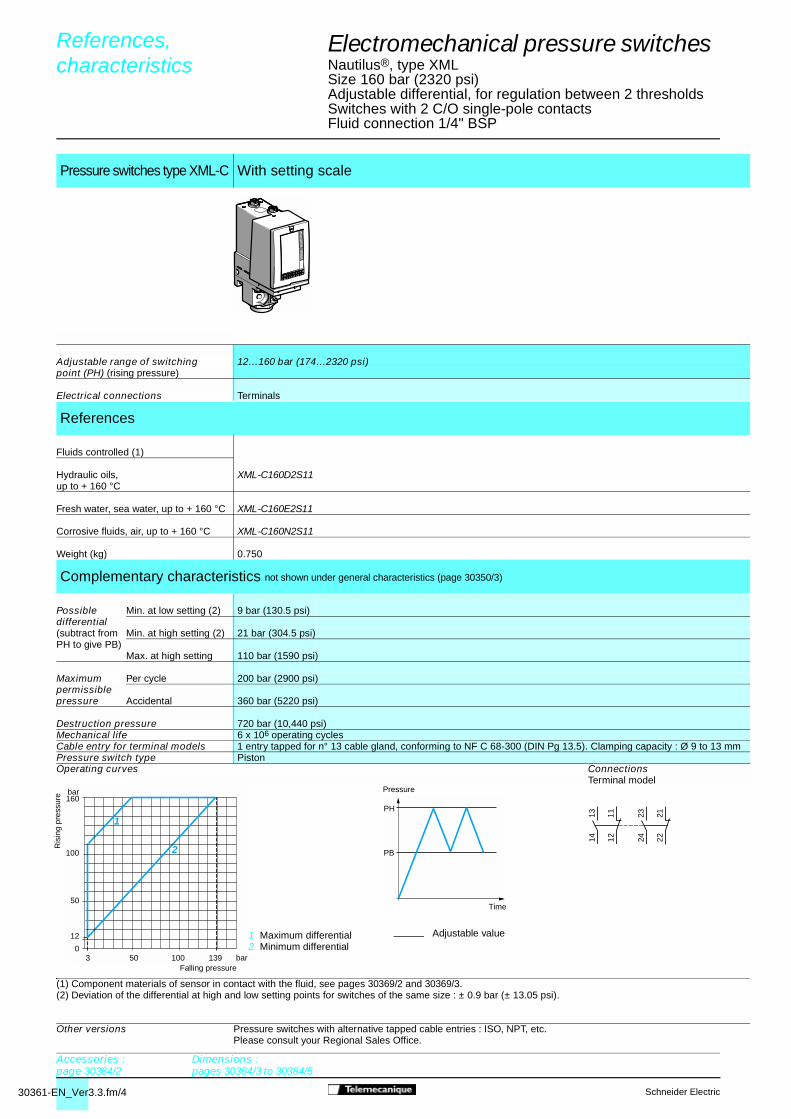
30361-EN_Ver3.3.fm/4 Schneider Electric
(1) Component materials of sensor in contact with the fluid, see pages 30369/2 and 30369/3.(2) Deviation of the differential at high and low setting points for switches of the same size : ± 0.9 bar (± 13.05 psi).
Pressure switches type XML-C With setting scale
Adjustable range of switching 12…160 bar (174…2320 psi)point (PH) (rising pressure)
Electrical connections Terminals
References
Fluids controlled (1)
Hydraulic oils, XML-C160D2S11up to + 160 °C
Fresh water, sea water, up to + 160 °C XML-C160E2S11
Corrosive fluids, air, up to + 160 °C XML-C160N2S11
Weight (kg) 0.750
Complementary characteristics not shown under general characteristics (page 30350/3)
Possible Min. at low setting (2) 9 bar (130.5 psi)differential(subtract from Min. at high setting (2) 21 bar (304.5 psi)PH to give PB)
Max. at high setting 110 bar (1590 psi)
Maximum Per cycle 200 bar (2900 psi)permissiblepressure Accidental 360 bar (5220 psi)
Destruction pressure 720 bar (10,440 psi)Mechanical life 6 x 10⁶ operating cyclesCable entry for terminal models 1 entry tapped for n° 13 cable gland, conforming to NF C 68-300 (DIN Pg 13.5). Clamping capacity : Ø 9 to 13 mmPressure switch type PistonOperating curves Connections
Terminal model
Other versions Pressure switches with alternative tapped cable entries : ISO, NPT, etc.Please consult your Regional Sales Office.
PH
PB
3 bar
bar
050
50
12
100 139
160
1
2100
2324 22
211314 12
11
References, 0
characteristics 0
Electromechanical pressure switches 4
Nautilus®, type XMLSize 160 bar (2320 psi)Adjustable differential, for regulation between 2 thresholdsSwitches with 2 C/O single-pole contactsFluid connection 1/4" BSP
Accessories :page 30364/2
Dimensions :pages 30364/3 to 30364/5
Time
Adjustable value
Pressure
Ris
ing
pres
sure
Falling pressure
1 Maximum differential2 Minimum differential
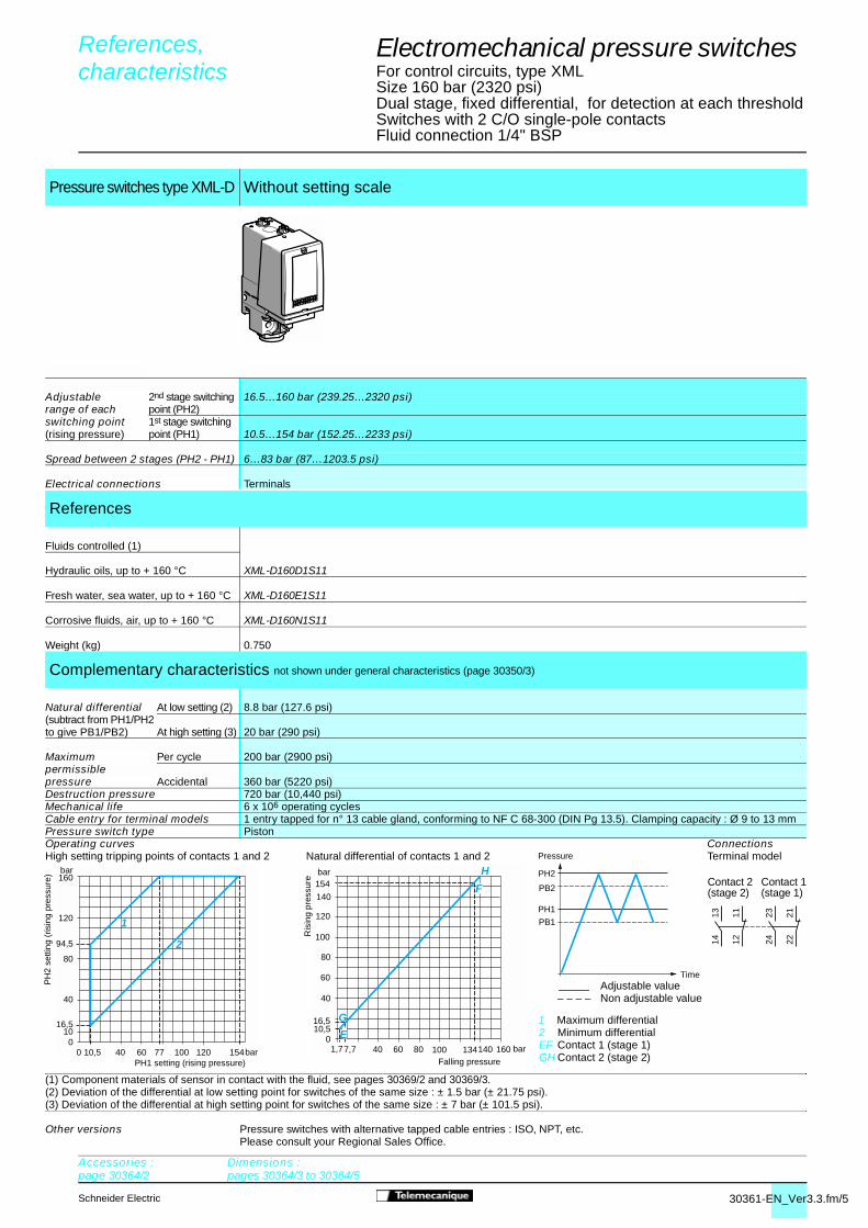
30361-EN_Ver3.3.fm/5Schneider Electric
0 10,5 bar
bar
040 7760
40
80
94,5
120
1016,5
120100 154
160
1
2
bar
bar
040 100 134140
40
100
1,77,7
10,516,5
160
60
80
120
140
154
60 80
E
F
H
G
PH2
PH1
PB1
PB2
2324 22
211314 12
11
References, 0
characteristics 0
Electromechanical pressure switches 4
For control circuits, type XMLSize 160 bar (2320 psi)Dual stage, fixed differential, for detection at each thresholdSwitches with 2 C/O single-pole contacts Fluid connection 1/4" BSP
(1) Component materials of sensor in contact with the fluid, see pages 30369/2 and 30369/3.(2) Deviation of the differential at low setting point for switches of the same size : ± 1.5 bar (± 21.75 psi).(3) Deviation of the differential at high setting point for switches of the same size : ± 7 bar (± 101.5 psi).
Pressure switches type XML-D Without setting scale
Adjustable 2nd stage switching 16.5…160 bar (239.25…2320 psi)range of each point (PH2)switching point 1st stage switching(rising pressure) point (PH1) 10.5…154 bar (152.25…2233 psi)
Spread between 2 stages (PH2 - PH1) 6…83 bar (87…1203.5 psi)
Electrical connections Terminals
References
Fluids controlled (1)
Hydraulic oils, up to + 160 °C XML-D160D1S11
Fresh water, sea water, up to + 160 °C XML-D160E1S11
Corrosive fluids, air, up to + 160 °C XML-D160N1S11
Weight (kg) 0.750
Complementary characteristics not shown under general characteristics (page 30350/3)
Natural differential At low setting (2) 8.8 bar (127.6 psi)(subtract from PH1/PH2to give PB1/PB2) At high setting (3) 20 bar (290 psi)
Maximum Per cycle 200 bar (2900 psi)permissiblepressure Accidental 360 bar (5220 psi)Destruction pressure 720 bar (10,440 psi)Mechanical life 6 x 10⁶ operating cyclesCable entry for terminal models 1 entry tapped for n° 13 cable gland, conforming to NF C 68-300 (DIN Pg 13.5). Clamping capacity : Ø 9 to 13 mmPressure switch type PistonOperating curves ConnectionsHigh setting tripping points of contacts 1 and 2 Natural differential of contacts 1 and 2 Terminal model
Other versions Pressure switches with alternative tapped cable entries : ISO, NPT, etc.Please consult your Regional Sales Office.
Accessories :page 30364/2
Dimensions :pages 30364/3 to 30364/5
1 Maximum differential2 Minimum differentialEF Contact 1 (stage 1)GH Contact 2 (stage 2)
Time Adjustable value
– – – – Non adjustable value
Pressure
PH
2 se
tting
(ris
ing
pres
sure
)
PH1 setting (rising pressure) Falling pressure
Contact 2(stage 2)
Contact 1(stage 1)
Ris
ing
pres
sure

30362-EN_Ver3.3.fm/2 Schneider Electric
3,5 bar
bar
0100 200 265 300
100
200
300
20
1314 12
11
321
PH
PB
Electromechanical pressure switches 4
Nautilus®, type XMLSize 300 bar (4350 psi)Fixed differential, for detection of a single threshold Switches with 1 C/O single-pole contactFluid connection 1/4" BSP
(1) Component materials of sensor in contact with the fluid, see pages 30369/2 and 30369/3.(2) Deviation of the differential at low setting point for switches of the same size : ± 3 bar (± 43.5 psi).(3) Deviation of the differential at high setting point for switches of the same size : ± 6 bar (± 87 psi).(4) Only for control of group 2 fluids, in accordance with directive 97/23/EEC.
Pressure switches type XML-A With setting scale Without setting scale
Adjustable range of switching 20…300 bar (290…4350 psi)point (PH) (rising pressure)
Electrical connections Terminals DIN connector Terminals DIN connector
References
Fluids controlled (1) (4)
Hydraulic oils, up to + 160°C XML-A300D2S11 XML-A300D2C11 XML-A300D1S11 XML-A300D1C11
Fresh water, sea water, XML-A300E2S11 XML-A300E2C11 XML-A300E1S11 XML-A300E1C11up to + 160°C
Corrosive fluids, air, up to + 160°C XML-A300N2S11 XML-A300N2C11 XML-A300N1S11 XML-A300N1C11
Weight (kg) 0.750 0.780 0.750 0.780
Complementary characteristics not shown under general characteristics (page 30350/3)
Natural differential At low setting (2) 16.5 bar (239.25 psi)(subtract fromPH to give PB) At high setting (3) 35 bar (507.5 psi)
Maximum Per cycle 375 bar (5437.5 psi)permissiblepressure Accidental 675 bar (9787.5 psi)
Destruction pressure 1350 bar (19,575 psi)
Mechanical life 3 x 10⁶ operating cyclesCable entry for terminal models 1 entry tapped for n°13 cable gland, conforming to NF C 68-300 (DIN Pg 13.5). Clamping capacity : Ø 9 to 13 mmConnector type for connector models DIN 43650A, 4-pin male. For suitable female connector, see page 30364/2Pressure switch type PistonOperating curves
Connector modelSwitch connector pin view
Other versions Pressure switches with alternative tapped entries : ISO, NPT, etc. Please consult your Regional Sales Office.
References, 0
characteristics 0
Falling pressureAdjustable valueNon adjustable value
Pressure
Time1 ��11 and 132 � 123 � 14
Accessories :page 30364/2
Dimensions :pages 30364/3 to 30364/
5
Ris
ing
pres
sure
ConnectionsTerminal model
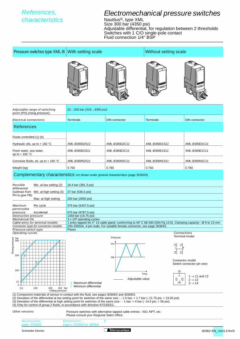
30362-EN_Ver3.3.fm/3Schneider Electric
1314 12
11
321
bar
bar
0
200
100
22
300
2632001002,6
2
1
PH
PB
Electromechanical pressure switches 4
Nautilus®, type XMLSize 300 bar (4350 psi)Adjustable differential, for regulation between 2 thresholdsSwitches with 1 C/O single-pole contactFluid connection 1/4" BSP
(1) Component materials of sensor in contact with the fluid, see pages 30369/2 and 30369/3.(2) Deviation of the differential at low setting point for switches of the same size : - 1.5 bar, + 1.7 bar (- 21.75 psi, + 24.65 psi).(3) Deviation of the differential at high setting point for switches of the same size : - 1 bar, + 4 bar (- 14.5 psi, + 58 psi).(4) Only for control of group 2 fluids, in accordance with directive 97/23/EEC.
Pressure switches type XML-B With setting scale Without setting scale
Adjustable range of switching 22…300 bar (319…4350 psi)point (PH) (rising pressure)
Electrical connections Terminals DIN connector Terminals DIN connector
References
Fluids controlled (1) (4)
Hydraulic oils, up to + 160 °C XML-B300D2S11 XML-B300D2C11 XML-B300D1S11 XML-B300D1C11
Fresh water, sea water, XML-B300E2S11 XML-B300E2C11 XML-B300E1S11 XML-B300E1C11up to + 160 °C
Corrosive fluids, air, up to + 160 °C XML-B300N2S11 XML-B300N2C11 XML-B300N1S11 XML-B300N1C11
Weight (kg) 0.750 0.780 0.750 0.780
Complementary characteristics not shown under general characteristics (page 30350/3)
Possible Min. at low setting (2) 19.4 bar (281.3 psi)differential(subtract from Min. at high setting (3) 37 bar (536.5 psi)PH to give PB)
Max. at high setting 200 bar (2900 psi)
Maximum Per cycle 375 bar (5437.5 psi)permissiblepressure Accidental 675 bar (9787.5 psi)Destruction pressure 1350 bar (19,75 psi)Mechanical life 3 x 10⁶ operating cyclesCable entry for terminal models 1 entry tapped for n° 13 cable gland, conforming to NF C 68-300 (DIN Pg 13.5). Clamping capacity : Ø 9 to 13 mmConnector type for connector models DIN 43650A, 4-pin male. For suitable female connector, see page 30364/2Pressure switch type PistonOperating curves Connections
Terminal model
Connector modelSwitch connector pin view
Other versions Pressure switches with alternative tapped cable entries : ISO, NPT, etc. Please consult your Regional Sales Office.
References, 0
characteristics 0
Pressure
Time
1 Maximum differential2 Minimum differential
1 � 11 and 132 � 123 � 14
Accessories :page 30364/2
Dimensions :pages 30364/3 to 30364/
5
Ris
ing
pres
sure
Falling pressure
Adjustable value
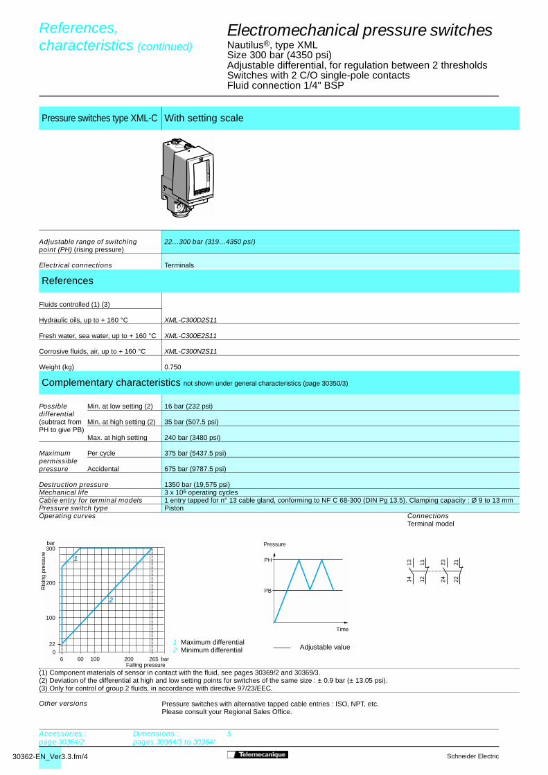
30362-EN_Ver3.3.fm/4 Schneider Electric
PH
PB
bar
bar
0
200
100
22
300
265200606
2
1
100
2324 22
211314 12
11
Electromechanical pressure switches 4
Nautilus®, type XMLSize 300 bar (4350 psi)Adjustable differential, for regulation between 2 thresholdsSwitches with 2 C/O single-pole contactsFluid connection 1/4" BSP
(1) Component materials of sensor in contact with the fluid, see pages 30369/2 and 30369/3.(2) Deviation of the differential at high and low setting points for switches of the same size : ± 0.9 bar (± 13.05 psi).(3) Only for control of group 2 fluids, in accordance with directive 97/23/EEC.
Pressure switches type XML-C With setting scale
Adjustable range of switching 22…300 bar (319…4350 psi)point (PH) (rising pressure)
Electrical connections Terminals
References
Fluids controlled (1) (3)
Hydraulic oils, up to + 160 °C XML-C300D2S11
Fresh water, sea water, up to + 160 °C XML-C300E2S11
Corrosive fluids, air, up to + 160 °C XML-C300N2S11
Weight (kg) 0.750
Complementary characteristics not shown under general characteristics (page 30350/3)
Possible Min. at low setting (2) 16 bar (232 psi)differential(subtract from Min. at high setting (2) 35 bar (507.5 psi)PH to give PB)
Max. at high setting 240 bar (3480 psi)
Maximum Per cycle 375 bar (5437.5 psi)permissiblepressure Accidental 675 bar (9787.5 psi)
Destruction pressure 1350 bar (19,575 psi)Mechanical life 3 x 10⁶ operating cyclesCable entry for terminal models 1 entry tapped for n° 13 cable gland, conforming to NF C 68-300 (DIN Pg 13.5). Clamping capacity : Ø 9 to 13 mmPressure switch type PistonOperating curves Connections
Terminal model
Other versions Pressure switches with alternative tapped cable entries : ISO, NPT, etc. Please consult your Regional Sales Office.
References, 0
characteristics (continued) 0
Accessories :page 30364/2
Dimensions :pages 30364/3 to 30364/
5
Ris
ing
pres
sure
Time
Adjustable value
Pressure
Falling pressure
1 Maximum differential2 Minimum differential

30362-EN_Ver3.3.fm/5Schneider Electric
bar
bar
0
200215
100
2036
300
2892001110 25
2
1
8 19 bar
bar
0100 200 247 258
100
200
300289
2536
E
G
H
F
300
PH2
PH1
PB1
PB2
2324 22
211314 12
11
Electromechanical pressure switches 4
Nautilus®, type XMLSize 300 bar (4350 psi)Dual stage, fixed differential, for detection at each thresholdSwitches with 2 C/O single-pole contacts Fluid connection 1/4" BSP
(1) Component materials of sensor in contact with the fluid, see pages 30369/2 and 30369/3.(2) Deviation of the differential at low setting point for switches of the same size : ± 2.5 bar (± 36.25 psi).(3) Deviation of the differential at high setting point for switches of the same size : ± 9 bar (± 130.5 psi).(4) Only for control of group 2 fluids, in accordance with directive 97/23/EEC.
Pressure switches type XML-D Without setting scale
Adjustable 2nd stage switching 36…300 bar (522…4350 psi)range of each point (PH2)switching point 1st stage switching(rising pressure) point (PH1) 25…289 bar (362.5…4190.5 psi)
Spread between 2 stages (PH2 - PH1) 11…189 bar (159.5…2740.5 psi)
Electrical connections Terminals
References
Fluids controlled (1) (4)
Hydraulic oils, up to + 160 °C XML-D300D1S11
Fresh water, sea water, up to + 160 °C XML-D300E1S11
Corrosive fluids, air, up to + 160 °C XML-D300N1S11
Weight (kg) 0.750
Complementary characteristics not shown under general characteristics (page 30350/3)
Natural differential At low setting (2) 17 bar (246.5 psi)(subtract from PH1/2to give PB1/2) At high setting (3) 42 bar (609 psi)
Maximum Per cycle 375 bar (5437.5 psi)permissiblepressure Accidental 675 bar (9787.5 psi)Destruction pressure 1350 bar (19,575 psi)Mechanical life 3 x 10⁶ operating cyclesCable entry for terminal models 1 entry tapped for n° 13 cable gland, conforming to NF C 68-300 (DIN Pg 13.5). Clamping capacity : Ø 9 to 13 mmPressure switch type PistonOperating curves ConnectionsHigh setting tripping points of contacts 1 and 2 Natural differential of contacts 1 and 2 Terminal model
Other versions Pressure switches with alternative tapped cable entries : ISO, NPT, etc. Please consult your Regional Sales Office.
References, 0
characteristics (continued) 0
Accessories :page 30364/2
Dimensions :pages 30364/3 to 30364/
5
1 Maximum differential2 Minimum differential EF Contact 1 (stage 1)GH Contact 2 (stage 2)
Time
Pressure
PH
2 se
tting
(ris
ing
pres
sure
)
PH1 setting (rising pressure) Falling pressure
Contact 2(stage 2)
Contact 1(stage 1)
Ris
ing
pres
sure
Adjustable value Non adjustable value

30363-EN_Ver3.3.fm/2 Schneider Electric
1314 12
11
321
bar
bar
0100 200 400
100
200
300
10
30
300
400
500
455
PH
PB
(1) Component materials of sensor in contact with the fluid, see pages 30369/2 and 30369/3.(2) Deviation of the differential at low setting point for switches of the same size : ± 6 bar (± 87 psi).(3) Deviation of the differential at high setting point for switches of the same size : ± 10 bar (± 145 psi).(4) Only for control of group 2 fluids, in accordance with directive 97/23/EEC.
Pressure switches type XML-A With setting scale Without setting scale
Adjustable range of switching 30…500 bar (435…7250 psi)point (PH) (rising pressure)
Electrical connections Terminals DIN connector Terminals DIN connector
References
Fluids controlled (1) (4)
Hydraulic oils, up to + 160 °C XML-A500D2S11 XML-A500D2C11 XML-A500D1S11 XML-A500D1C11
Fresh water, sea water, up to + 160 °C XML-A500E2S11 XML-A500E2C11 XML-A500E1S11 XML-A500E1C11
Corrosive fluids, air, up to + 160 °C XML-A500N2S11 XML-A500N2C11 XML-A500N1S11 XML-A500N1C11
Weight (kg) 0.750 0.780 0.750 0.780
Complementary characteristics not shown under general characteristics (page 30350/3)
Natural differential At low setting (2) 20 bar (290 psi)(subtract fromPH to give PB) At high setting (3) 45 bar (652.5 psi)
Maximum Per cycle 625 bar (9062.5 psi)permissiblepressure Accidental 1125 bar (16,312.5 psi)
Destruction pressure 2250 bar (32,625 psi)Mechanical life 3 x 10⁶ operating cyclesCable entry for terminal models 1 entry tapped for n° 13 cable gland, conforming to NF C 68-300 (DIN Pg 13.5). Clamping capacity : Ø 9 to 13 mmConnector type for connector models DIN 43650A, 4-pin male. For suitable female connector, see page 30364/2Pressure switch type PistonOperating curves Connections
Terminal model
Connector modelSwitch connector pin view
Other versions Pressure switches with alternative tapped cable entries : ISO, NPT, etc. Please consult your Regional Sales Office.
Electromechanical pressure switches 4
Nautilus®, type XMLSize 500 bar (7250 psi)Fixed differential, for detection of a single threshold Switches with 1 C/O single-pole contactFluid connection 1/4" BSP
References, 0
characteristics 0
Falling pressure
Adjustable value – – – – Non adjustable value
Pressure
Time
1 � 11 and 132 � 123 � 14
Accessories :page 30364/2
Dimensions :pages 30364/3 to 30364/5
Ris
ing
pres
sure

30363-EN_Ver3.3.fm/3Schneider Electric
(1) Component materials of sensor in contact with the fluid, see pages 30369/2 and 30369/3.(2) Deviation of the differential at low setting point for switches of the same size : - 2.6 bar, + 3.8 bar (- 37.7 psi, + 55.1 psi).(3) Deviation of the differential at high setting point for switches of the same size : - 14.8 bar, + 11.2 bar (- 214.6 psi, + 162.4 psi).(4) Only for control of group 2 fluids, in accordance with directive 97/23/EEC.
Pressure switches type XML-B With setting scale Without setting scale
Adjustable range of switching 30…500 bar (435…7250 psi)point (PH) (rising pressure)
Electrical connections Terminals DIN connector Terminals DIN connector
References
Fluids controlled (1) (4)
Hydraulic oils, up to + 160 °C XML-B500D2S11 XML-B500D2C11 XML-B500D1S11 XML-B500D1C11
Fresh water, sea water, up to + 160 °C XML-B500E2S11 XML-B500E2C11 XML-B500E1S11 XML-B500E1C11
Corrosive fluids, air, up to + 160 °C XML-B500N2S11 XML-B500N2C11 XML-B500N1S11 XML-B500N1C11
Weight (kg) 0.750 0.780 0.750 0.780
Complementary characteristics not shown under general characteristics (page 30350/3)
Possible Min. at low setting (2) 23 bar (333.5 psi)differential(subtract from Min. at high setting (3) 52.6 bar (762.7 psi)PH to give PB)
Max. at high setting 300 bar (4350 psi)
Maximum Per cycle 625 bar (9062.5 psi)permissiblepressure Accidental 1125 bar (16,312.5 psi)Destruction pressure 2250 bar (32,625 psi)Mechanical life 3 x 10⁶ operating cyclesCable entry for terminal models 1 entry tapped for n° 13 cable gland, conforming to NF C 68-300 (DIN Pg 13.5). Clamping capacity : Ø 9 to 13 mmConnector type for connector models DIN 43650A, 4-pin male. For suitable female connector, see page 30364/2Pressure switch type PistonOperating curves Connections
Terminal model
Connector modelSwitch connector pin view
Other versions Pressure switches with alternative tapped cable entries : ISO, NPT, etc. Please consult your Regional Sales Office.
1314 12
11
321
bar
bar
0100 200 447,4400
100
200
300
7
30
400
500
2
1
PH
PB
Ris
ing
pres
sureElectromechanical pressure switches 4
Nautilus®, type XMLSize 500 bar (7250 psi)Adjustable differential, for regulation between 2 thresholdsSwitches with 1 C/O single-pole contactFluid connection 1/4" BSP
References, 0
characteristics 0
Pressure
Time Adjustable value
1 Maximum differential2 Minimum differential
Falling pressure
1 � 11 and 132 � 123 � 14
Accessories :page 30364/2
Dimensions :pages 30364/3 to 30364/5

30363-EN_Ver3.3.fm/4 Schneider Electric
PH
PB
bar
bar
0100 160 300 448400
100
200
300
11
30
400
500
2
1
200
2324 22
211314 12
11
(1) Component materials of sensor in contact with the fluid, see pages 30369/2 and 30369/3.(2) Deviation of the differential at high and low setting points for switches of the same size : ± 0.9 bar (± 13.05 psi).(3) Only for control of group 2 fluids, in accordance with directive 97/23/EEC.
Pressure switches type XML-C With setting scale
Adjustable range of switching 30…500 bar (435…7250 psi)point (PH) (rising pressure)
Electrical connections Terminals
References
Fluids controlled (1) (3)
Hydraulic oils, XML-C500D2S11up to + 160 °C
Fresh water, sea water, up to + 160 °C XML-C500E2S11
Corrosive fluids, air, up to + 160 °C XML-C500N2S11
Weight (kg) 0.750
Complementary characteristics not shown under general characteristics (page 30350/3)
Possible Min. at low setting (2) 19 bar (275.5 psi)differential(subtract from Min. at high setting (2) 52 bar (754 psi)PH to give PB)
Max. at high setting 340 bar (4930 psi)
Maximum Per cycle 625 bar (9062.5 psi)permissiblepressure Accidental 1125 bar (16,312.5 psi)
Destruction pressure 2250 bar (32,625 psi)Mechanical life 3 x 10⁶ operating cyclesCable entry for terminal models 1 entry tapped for n° 13 cable gland, conforming to NF C 68-300 (DIN Pg 13.5). Clamping capacity : Ø 9 to 13 mmPressure switch type PistonOperating curves Connections
Terminal model
Other versions Pressure switches with alternative tapped cable entries : ISO, NPT, etc. Please consult your Regional Sales Office.
Electromechanical pressure switches 4
Nautilus®, type XMLSize 500 bar (7250 psi)Adjustable differential, for regulation between 2 thresholdsSwitches with 2 C/O single-pole contactsFluid connection 1/4" BSP
References, 0
characteristics 0
Accessories :page 30364/2
Dimensions :pages 30364/3 to 30364/5
Adjustable value
Pressure
Falling pressure
1 Maximum differential2 Minimum differential
Ris
ing
pres
sure
Time

30363-EN_Ver3.3.fm/5Schneider Electric
bar
bar
0100 200 256300 484400
100
200
273,5300
25
41
400
500
2
1
bar
bar
0100 200 419
100
200
300
4 20
2541
300
400
484
435
GE
FH PH2
PH1
PB1
PB2
2324 22
211314 12
11
(1) Component materials of sensor in contact with the fluid, see pages 30369/2 and 30369/3.(2) Deviation of the differential at low setting point for switches of the same size : ± 3 bar (± 43.5 psi).(3) Deviation of the differential at high setting point for switches of the same size : ± 10 bar (± 145 psi).(4) Only for control of group 2 fluids, in accordance with directive 97/23/EEC.
Pressure switches type XML-D Without setting scale
Adjustable 2nd stage switching 41…500 bar (594.5…7250 psi)range of each point (PH2)switching point 1st stage switching(rising pressure) point (PH1) 25…484 bar (362.5…7018 psi)
Spread between 2 stages (PH2 - PH1) 16…244 bar (232…3538 psi)
Electrical connections Terminals
References
Fluids controlled (1) (4)
Hydraulic oils, up to + 160 °C XML-D500D1S11
Fresh water, sea water, up to + 160 °C XML-D500E1S11
Corrosive fluids, air, up to + 160 °C XML-D500N1S11
Weight (kg) 0.750
Complementary characteristics not shown under general characteristics (page 30350/3)
Natural differential At low setting (2) 21 bar (304.5 psi)(subtract from PH1/2to give PB1/2) At high setting (3) 65 bar (942.5 psi)
Maximum Per cycle 625 bar (9062.5 psi)permissiblepressure Accidental 1125 bar (16,312.5 psi)Destruction pressure 2250 bar (32,625 psi)Mechanical life 3 x 10⁶ operating cyclesCable entry for terminal models 1 entry tapped for n° 13 cable gland, conforming to NF C 68-300 (DIN Pg 13.5). Clamping capacity : Ø 9 to 13 mmPressure switch type PistonOperating curves ConnectionsHigh setting tripping points of contacts 1 and 2 Natural differential of contacts 1 and 2 Terminal model
Other versions Pressure switches with alternative tapped cable entries : ISO, NPT, etc. Please consult your Regional Sales Office.
Electromechanical pressure switches 4
Nautilus®, type XMLSize 500 bar (7250 psi)Dual stage, fixed differential, for detection at each thresholdSwitches with 2 C/O single-pole contactsFluid connection 1/4" BSP
References, 0
characteristics 0
Accessories :page 30364/2
Dimensions :pages 30364/3 to 30364/5
1 Maximum differential2 Minimum differentialEF Contact 1 (stage 1)GH Contact 2 (stage 2)
Time
Adjustable valueNon adjustable value
Pressure
PH
2 se
tting
(ris
ing
pres
sure
)
PH1 setting (rising pressure) Falling pressure
Contact 2 (stage 2)
Contact 1(stage 1)
Ris
ing
pres
sure

30364-EN_Ver4.3.fm/2 Schneider Electric
Electromechanical pressure and vacuum switches 4
Nautilus®, types XML-A, XML-B, XML-C, XML-DAccessories and replacement part
Accessories for pressure switches and vacuum switches
Description Specific characteristics
For use with switches Reference Weightkg
Rear fixing bracketfor vibrations > 2 gn
– XML pL35XML p001
XML ZL006 0.230
Additional top support bracketfor vibrations > 4 gn
– XML AM01XML pM05XML A004XML p010 toXML p500
XML ZL002 0.020
Knurled adjustment knob, Ø 36 mmfits over adjustment screw(s)to facilitate setting
– All models XML ZL003 0.010
Fixing platefor replacing an XMJ A or XMG Bswitch by an XML switch
– XML AM01XML pM05XML A004XML p010 toXML p500
XML ZL004 0.110
Lead sealable protective coverto prevent unauthorised access to adjustment screws and fixing screw of switch cover
XML AXML B
XML ZL001 0.035
Indicator modules andassociatedcovers,2 LEDs (orangeand green)
Withoutsetting scale
a or c 24/48 V XML A/B XML ZZ024 0.090
a 110/240 V XML A/B XML ZZ120 0.090
Withsetting scale
a or c 24/48 V XML A XML ZA024 0.090
XML B XML ZB024 0.090
a 110/240 V XML A XML ZA120 0.090
XML B XML ZB120 0.090
Hydraulic block for basemounting directly ontofluid manifold
– All models XML ZL005 0.240
Female connector, typeDIN 43650A
– XML ppppppC11 XZ CC43FCP40B 0.035
Extension cablesDIN 43650A - straight M12 malefor splitter boxes(see connections, page 30368/3)
L = 1 m XML ppppppC11 XZ CR1523062K1 0.080
L = 2 m XML ppppppC11 XZ CR1523062K2 0.110
Marker holder8 x 17 mm, clip-in(Sold in lots of 100)
– All models LA9 D90 0.001
Referenced markersclip-in, 10 maximumper switch(Sold in lots of 25)
Markers tag strip of 10 identicalnumbers (0 to 9)according to thereference
All models AB1 Rp (1) 0.002
Markers tag strip of 10 identical capital letters(A to Z) according to the reference
All models AB1 Gp (1) 0.002
Replacement part
Sealing gasket For sizes u 300 bar (XML A/B/C/D) XML ZL010 0.015
(1) Complete the reference with the number or letter required.
XML ZL006
XML ZL003 XML ZL004
XML ZL001 XML ZL002
XML ZL005
XML ZAppp, XML ZBppp
XZ CC43FCP40B
XML ZL010
References 0

30364-EN_Ver4.3.fm/3Schneider Electric
Electromechanical pressure and vacuum switches 4
Nautilus®, types XML-A, XML-B, XML-C, XML-D
XML pL35, XML p001, XML pS
(1) 1 fluid entry, tapped G 1/4 (BSP female)(2) 1 electrical connections entry, tapped for n° 13 cable gland
XML BM03, XML BL05
(1) 1 fluid entry, tapped G 1/4 (BSP female)(2) 1 electrical connections entry, tapped for n° 13 cable gland(3) 2 elongated holes Ø 5.2 x 10.2(4) 1 elongated hole Ø 5.2 x 15.2
XML Øa c1 c2BM03 150 155.5 80.5BL05 200 204 104pL35, p001 110 – –pS35, pS02, pS04 113 – –pS10, pS20 86 – –
56,5
17
45 ==57
(1)
(2)
XML-C/D : 46XML-A/B : 35
max
162
a
c1
40
20 20
145
56
65
10
(3)
(4)
c2(1)
(2)
Ø5,2
Øa
Dimensions 0
Characteristics :pages 30350/3 to 30363/5
References :pages 30351/2 to 30363/5

30364-EN_Ver4.3.fm/4 Schneider Electric
Electromechanical pressure and vacuum switches 4
Nautilus®, types XML-A, XML-B, XML-C, XML-D
XML AM01, XML BM05, XML CM05, XML A004, XML p010…500
(1) 1 fluid entry, tapped G 1/4 (BSP female)(2) 1 electrical connections entry, tapped for n° 13 cable glandØ : 2 elongated holes 5.2 x 6.7
XML pM02, XML p002, XML B004, XML C004, XML D004
(1) 1 fluid entry, tapped G 1/4 (BSP female)(2) 1 electrical connections entry, tapped for n° 13 cable glandØ : 2 elongated holes Ø 5.2 x 6.7
37
(2)
XML-A/B : 75
23(1)
37 5
56
120
XML-C/D : 46
XML-A/B : 35
20-22= =11
3
17,5
XML-C/D : 85
XML-A/B : 77,5
XML-C/D : 46
XML-A/B : 35XML-C/D : 90
1334
55
37-40= =30
158
Ø
(2)
(1)
122
Ø5,2
106
Dimensions (continued) 0
Characteristics :pages 30350/3 to 30363/5
References :pages 30351/2 to 30363/5
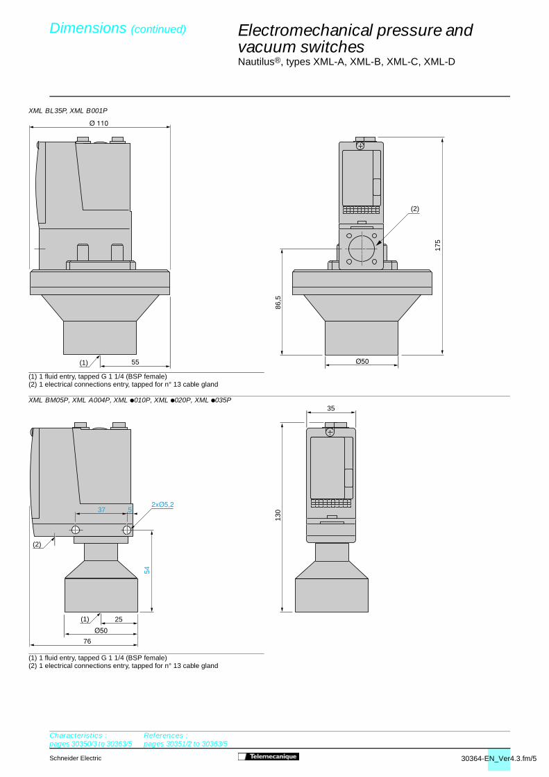
30364-EN_Ver4.3.fm/5Schneider Electric
Electromechanical pressure and vacuum switches 4
Nautilus®, types XML-A, XML-B, XML-C, XML-D
XML BL35P, XML B001P
(1) 1 fluid entry, tapped G 1 1/4 (BSP female)(2) 1 electrical connections entry, tapped for n° 13 cable gland
XML BM05P, XML A004P, XML p010P, XML p020P, XML p035P
(1) 1 fluid entry, tapped G 1 1/4 (BSP female)(2) 1 electrical connections entry, tapped for n° 13 cable gland
86,5
175
55(1)
(2)
130
54
(2)
76
35
25(1)
37 5
Dimensions (continued) 0
Characteristics :pages 30350/3 to 30363/5
References :pages 30351/2 to 30363/5
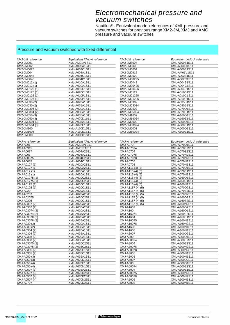
30370-EN_Ver3.3.fm/2 Schneider Electric
Electromechanical pressure and vacuum switches 4
Nautilus® - Equivalent model references of XML pressure and vacuum switches for previous range XM2-JM, XMJ and XMG pressure and vacuum switches
Pressure and vacuum switches with fixed differential
XM2-JM reference Equivalent XML-A reference XM2-JM reference Equivalent XML-A referenceXM2-JM091 XML-AM01V1S11 XM2-JM3004 XML-A300E1S11XM2-JM002 XML-A002A1S11 XM2-JM500 XML-A500D1S11XM2-JM0025 XML-A002C1S11 XM2-JM5004 XML-A500E1S11XM2-JM004 XML-A004A1S11 XM2-JM0912 XML-AM01V1S11XM2-JM0045 XML-A004C1S11 XM2-JM0022 XML-A002B1S11XM2-JM0046 XML-A004P1S11 XM2-JM00225 XML-A002C1S11XM2-JM012 (1) XML-A010A1S11 XM2-JM0042 XML-A004B1S11XM2-JM012 (1) XML-A020A1S11 XM2-JM00425 XML-A004C1S11XM2-JM0125 (1) XML-A010C1S11 XM2-JM00426 XML-A004P1S11XM2-JM0125 (1) XML-A020C1S11 XM2-JM0122 XML-A010B1S11XM2-JM0126 (1) XML-A010P1S11 XM2-JM01225 XML-A010C1S11XM2-JM0126 (1) XML-A020P1S11 XM2-JM01226 XML-A010P1S11XM2-JM030 (2) XML-A020A1S11 XM2-JM0302 XML-A035B1S11XM2-JM030 (2) XML-A035A1S11 XM2-JM03024 XML-A035B1S11XM2-JM0304 (2) XML-A020A1S11 XM2-JM0502 XML-A070D1S11XM2-JM0304 (2) XML-A035A1S11 XM2-JM05024 XML-A070E1S11XM2-JM050 (3) XML-A035A1S11 XM2-JM1602 XML-A160D1S11XM2-JM050 (3) XML-A070D1S11 XM2-JM16024 XML-A160E1S11XM2-JM0504 (3) XML-A035A1S11 XM2-JM3002 XML-A300D1S11XM2-JM0504 (3) XML-A070E1S11 XM2-JM30024 XML-A300E1S11XM2-JM160 XML-A160D1S11 XM2-JM5002 XML-A500D1S11XM2-JM1604 XML-A160E1S11 XM2-JM50024 XML-A500E1S11XM2-JM300 XML-A300D1S11
XMJ-A reference Equivalent XML-A reference XMJ-A reference Equivalent XML-A referenceXMJ-A091 XML-AM01V1S11 XMJ-A070 XML-A070D1S11XMJ-A0915 XML-AM01T1S11 XMJ-A07074 XML-A070E2S11XMJ-A0037 XML-A004A2S11 XMJ-A0704 XML-A070E1S11XMJ-A003 XML-A004A1S11 XMJ-A07075 XML-A070N2S11XMJ-A00375 XML-A004C2S11 XMJ-A07078 XML-A070N2S11XMJ-A0035 XML-A004C1S11 XMJ-A0705 XML-A070N1S11XMJ-A0127 (1) XML-A010A2S11 XMJ-A0708 XML-A070N1S11XMJ-A0127 (1) XML-A020A2S11 XMJ-A115 (4) (5) XML-A070D1S11XMJ-A012 (1) XML-A010A1S11 XMJ-A115 (4) (5) XML-A070E1S11XMJ-A012 (1) XML-A020A1S11 XMJ-A115 (4) (5) XML-A070N1S11XMJ-A01275 (1) XML-A010C2S11 XMJ-A115 (4) (5) XML-A160D1S11XMJ-A01275 (1) XML-A020C2S11 XMJ-A115 (4) (5) XML-A160E1S11XMJ-A0125 (1) XML-A010C1S11 XMJ-A115 (4) (5) XML-A160N1S11XMJ-A0125 (1) XML-A020C1S11 XMJ-A1157 (4) (5) XML-A070D2S11XMJ-A020 XML-A020A1S11 XMJ-A1157 (4) (5) XML-A070E2S11XMJ-A0207 XML-A020A2S11 XMJ-A1157 (4) (5) XML-A070N2S11XMJ-A02075 XML-A020C2S11 XMJ-A1157 (4) (5) XML-A160D2S11XMJ-A0205 XML-A020C1S11 XMJ-A1157 (4) (5) XML-A160E2S11XMJ-A0307 (2) XML-A020A2S11 XMJ-A1157 (4) (5) XML-A160N2S11XMJ-A0307 (2) XML-A035A2S11 XMJ-A1607 XML-A160D2S11XMJ-A03074 (2) XML-A020A2S11 XMJ-A160 XML-A160D1S11XMJ-A03074 (2) XML-A035A2S11 XMJ-A16074 XML-A160E2S11XMJ-A03078 (2) XML-A020A2S11 XMJ-A1604 XML-A160E1S11XMJ-A03078 (2) XML-A035A2S11 XMJ-A16075 XML-A160N2S11XMJ-A030 (2) XML-A020A1S11 XMJ-A16078 XML-A160N2S11XMJ-A030 (2) XML-A035A1S11 XMJ-A1605 XML-A160N1S11XMJ-A0304 (2) XML-A020A1S11 XMJ-A1608 XML-A160N1S11XMJ-A0304 (2) XML-A035A1S11 XMJ-A3007 XML-A300D2S11XMJ-A0308 (2) XML-A020A1S11 XMJ-A300 XML-A300D1S11XMJ-A0308 (2) XML-A035A1S11 XMJ-A30074 XML-A300E2S11XMJ-A03075 (2) XML-A020C2S11 XMJ-A3004 XML-A300E1S11XMJ-A03075 (2) XML-A035C2S11 XMJ-A30075 XML-A300N2S11XMJ-A0305 (2) XML-A020C1S11 XMJ-A30078 XML-A300N2S11XMJ-A0305 (2) XML-A035C1S11 XMJ-A3005 XML-A300N1S11XMJ-A050 (3) XML-A035A1S11 XMJ-A3008 XML-A300N1S11XMJ-A050 (3) XML-A070D1S11 XMJ-A5007 XML-A500D2S11XMJ-A050 (4) XML-A070E1S11 XMJ-A500 XML-A500D1S11XMJ-A050 (4) XML-A070N1S11 XMJ-A50074 XML-A500E2S11XMJ-A0507 (3) XML-A035A2S11 XMJ-A5004 XML-A500E1S11XMJ-A0507 (3) XML-A070D2S11 XMJ-A50075 XML-A500N2S11XMJ-A0507 (4) XML-A070E2S11 XMJ-A50078 XML-A500N2S11XMJ-A0507 (4) XML-A070N2S11 XMJ-A5005 XML-A500N1S11XMJ-A0707 XML-A070D2S11 XMJ-A5008 XML-A500N1S11
0

30370-EN_Ver3.3.fm/3Schneider Electric
Electromechanical pressure and vacuum switches 4
Nautilus® - Equivalent model references of XML pressure and vacuum switches for previous range XM2-JM, XMJ and XMG pressure and vacuum switches
Pressure and vacuum swithes with adjustable differential
XMG-B Equivalent XMG-B Equivalent XMG-B Equivalent XMG-B Equivalentreference XML-B reference reference XML-C reference reference XML-B reference reference XML-C referenceXMG-B091 XML-BM02V2S11 XMG-B0912 XML-CM02V2S11 XMG-B0146 (1) XML-B020P2S11 XMG-B01462 (8)XMG-B092 XML-BM02V2S11 XMG-B0922 XML-CM02V2S11 XMG-B0286 (6) XML-B020P2S11 XMG-B02862 (8)XMG-B093 XML-BM04V2S11 (8) XMG-B0932 XML-CM02V2S11 XMG-B0286 (6) XML-B035P2S11 XMG-B02862 (8)XMG-B0911 XML-BM02T2S11 XMG-B09112 XML-CM02T2S11 XMG-B070 XML-B070D2S11 XMG-B0702 XML-C070D2S11XMG-B0921 XML-BM02T2S11 XMG-B09212 XML-CM02T2S11 XMG-B140 XML-B160D2S11 XMG-B1402 XML-C160D2S11XMG-B0917 XML-BM02T2S11 XMG-B09172 XML-CM02T2S11 XMG-B280 XML-B300D2S11 XMG-B2802 XML-C300D2S11XMG-B0927 XML-BM02T2S11 XMG-B09272 XML-CM02T2S11 XMG-B500 XML-B500D2S11 XMG-B5002 XML-C500D2S11XMG-B001 (4) XML-BL35R2S11 XMG-B0012 (4) XML-CL35R2S11 XMG-B0704 XML-B070E2S11 XMG-B07042 XML-C070E2S11XMG-B001 (4) XML-BL35S2S11 XMG-B0012 (4) XML-CL35S2S11 XMG-B1404 XML-B160E2S11 XMG-B14042 XML-C160E2S11XMG-B002 XML-B002A2S11 XMG-B0022 XML-C002A2S11 XMG-B2804 XML-B300E2S11 XMG-B28042 XML-C300E2S11XMG-B003 XML-B004A2S11 XMG-B0032 XML-C004A2S11 XMG-B5004 XML-B500E2S11 XMG-B50042 XML-C500E2S11XMG-B008 XML-B010A2S11 XMG-B0082 XML-C010A2S11 XMG-B0708 XML-B070N2S11 XMG-B07082 XML-C070N2S11XMG-B014 (1) XML-B010A2S11 XMG-B0142 (1) XML-C010A2S11 XMG-B1408 XML-B160N2S11 XMG-B14082 XML-C160N2S11XMG-B014 (1) XML-B020A2S11 XMG-B0142 (1) XML-C020A2S11 XMG-B2808 XML-B300N2S11 XMG-B28082 XML-C300N2S11XMG-B028 (6) XML-B020A2S11 XMG-B0282 (6) XML-C020A2S11 XMG-B5008 XML-B500N2S11 XMG-B50082 XML-C500N2S11XMG-B028 (6) XML-B035A2S11 XMG-B0282 (6) XML-C035A2S11 XMG-B0701 (4) XML-B070D2S11 XMG-B07012 (4) XML-C070D2S11XMG-B0011 (4) XML-BL35R2S11 XMG-B00112 (4) XML-CL35R2S11 XMG-B0701 (4) XML-B070E2S11 XMG-B07012 (4) XML-C070E2S11XMG-B0011 (4) XML-BL35S2S11 XMG-B00112 (4) XML-CL35S2S11 XMG-B1401 (4) XML-B160D2S11 XMG-B14012 (4) XML-C160D2S11XMG-B0021 XML-B002B2S11 XMG-B00212 XML-C002B2S11 XMG-B1401 (4) XML-B160E2S11 XMG-B14012 (4) XML-C160E2S11XMG-B0031 XML-B004B2S11 XMG-B00312 XML-C004B2S11 XMG-B2801 (4) XML-B300D2S11 XMG-B28012 (4) XML-C300D2S11XMG-B0081 XML-B010B2S11 XMG-B00812 XML-C010B2S11 XMG-B2801 (4) XML-B300E2S11 XMG-B28012 (4) XML-C300E2S11XMG-B0141 (1) XML-B010B2S11 XMG-B01412 (1) XML-C010B2S11 XMG-B5001 (4) XML-B500D2S11 XMG-B50012 (4) XML-C500D2S11XMG-B0141 (1) XML-B020B2S11 XMG-B01412 (1) XML-C020B2S11 XMG-B5001 (4) XML-B500E2S11 XMG-B50012 (4) XML-C500E2S11XMG-B0281 (6) XML-B020B2S11 XMG-B02812 (6) XML-C020B2S11 XMG-B0707 XML-B070N2S11 XMG-B07072 XML-C070N2S11XMG-B0281 (6) XML-B035B2S11 XMG-B02812 (6) XML-C035B2S11 XMG-B1407 XML-B160N2S11 XMG-B14072 XML-C160N2S11XMG-B0017 XML-BL35S2S11 XMG-B00172 XML-CL35S2S11 XMG-B2807 XML-B300N2S11 XMG-B28072 XML-C300N2S11XMG-B0027 XML-B002C2S11 XMG-B00272 XML-C002C2S11 XMG-B5007 XML-B500N2S11 XMG-B50072 XML-C500N2S11XMG-B0037 XML-B004C2S11 XMG-B00372 XML-C004C2S11 XMG-B0018 XML-BS35R2S11 XMG-B00182 XML-CS35R2S11XMG-B0087 XML-B010C2S11 XMG-B00872 XML-C010C2S11 XMG-B0028 XML-BS02B2S11 XMG-B00282 XML-CS02B2S11XMG-B0147 (1) XML-B010C2S11 XMG-B01472 (1) XML-C010C2S11 XMG-B0038 XML-BS04B2S11 XMG-B00382 XML-CS04B2S11XMG-B0147 (1) XML-B020C2S11 XMG-B01472 (1) XML-C020C2S11 XMG-B0088 XML-BS10A2S11 (7) XMG-B00882 XML-CS10A2S11 (7)XMG-B0287 (6) XML-B020C2S11 XMG-B02872 (6) XML-C020C2S11 XMG-B0148 (1) XML-BS10A2S11 (7) XMG-B01482 (1) XML-CS10A2S11 (7)XMG-B0287 (6) XML-B035C2S11 XMG-B02872 (6) XML-C035C2S11 XMG-B0148 (1) XML-BS20A2S11 (7) XMG-B01482 (1) XML-CS20A2S11 (7)XMG-B0016 XML-BL35P2S11 XMG-B00162 (8) XMG-B0120 (5) (4) XML-B070D2S11 XMG-B01202 (5) (4) XML-C070D2S11XMG-B0026 XML-B002P2S11 XMG-B00262 (8) XMG-B0120 (5) (4) XML-B070E2S11 XMG-B01202 (5) (4) XML-C070E2S11XMG-B0036 XML-B004P2S11 XMG-B00362 (8) XMG-B0120 (5) (4) XML-B160D2S11 XMG-B01202 (5) (4) XML-C160D2S11XMG-B0086 XML-B010P2S11 XMG-B00862 (8) XMG-B0120 (5) (4) XML-B160E2S11 XMG-B01202 (5) (4) XML-C160E2S11XMG-B0146 (1) XML-B010P2S11 XMG-B01462 (8)
(1) Depending on required adjustment range, examples: pressure < 8 bar = XML-A/B/C010,pressure > 8 bar = XML-A/B/C020.
(2) Depending on required adjustment range, examples: pressure < 18 bar = XML-A/B/C020,pressure > 18 bar = XML-A/B/C035.
(3) Depending on required adjustment range, examples: pressure < 32 bar = XML-A/B/C035,pressure > 32 bar = XML-A/B/C070.
(4) Depending on fluid to be controlled.
(5) Depending on required adjustment range, examples: pressure < 65 bar = XML-A/B/C070,pressure > 65 bar = XML-A/B/C160.
(6) Depending on required adjustment range, examples: pressure < 18 bar = XML-A/B/C020,pressure > 18 bar = XML-A/B/C035.
(7) Temperature of fluid to be controlled limited to 70 °C.
(8) Please consult your Regional Sales Office.
0

30369-EN_Ver4.2.fm/2 Schneider Electric
Electromechanical pressure and vacuum switches 4
Nautilus®, type XML
Component materials in contact with the fluidZinc alloy Stainless Brass Steel Nitrile PTFE FPM, FKM Aluminium
Pressure or vacuum switch reference steel
XML-AM01Vpppp, XML-pM02Vpppp (1)
XML-AM01Tpppp, XML-pM02Tpppp (1)
XML-BM03Rpppp (1)
XML-BM03Spppp (1)
XML-pM05Apppp (1)
XML-pM05Bpppp (1)
XML-pM05Cpppp (1)
XML-BM05Ppppp (1)
XML-BL05Rpppp
XML-BL05Spppp (2)
XML-pL35Rpppp, XML-pS35Rpppp (2)
XML-pL35Spppp (2)
XML-BL35Ppppp (2)
XML-p001Rpppp (2)
XML-p001Spppp (2)
XML-B001Ppppp (2)
XML-p002Apppp
XML-p002Bpppp, XML-pS02Bpppp
XML-p002Cpppp (2)
XML-A004Apppp
XML-A004Bpppp
XML-A004Cpppp (2)
XML-A004Ppppp
Component materials of switch in contact with the fluid0
This information will assist in checking the corrosion resistance of the switches in relation to the fluids controlled
Materials in contact with the fluid

30369-EN_Ver4.2.fm/3Schneider Electric
Electromechanical pressure and vacuum switches 4
Nautilus®, type XML
(1) X2GNiMo 17-12-2 (AISI 316L)(2) X8GNiS 18-09 (AISI 303)(3) X2GNiMo 17-12-2 (AISI 316L) + X2CrNiMoN 22-5-3(4) X2GNiMo 17-12-2 (AISI 316L) + X8GNiS 18-09 (AISI 303)
Component materials in contact with the fluidZinc alloy Stainless Brass Steel Nitrile PTFE FPM, FKM Aluminium
Pressure switch reference steel
XML-B004Apppp
XML-p004Bpppp, XML-pS04Bpppp
XML-p004Cpppp (2)
XML-p010Apppp
XML-p010Bpppp
XML-p010Cpppp (1)
XML-p010Ppppp, XML-pS10Apppp
XML-p020Apppp, XML-p035Apppp
XML-p020Bpppp, XML-p035Bpppp
XML-p020Cpppp, XML-p035Cpppp (1)
XML-p020Ppppp, XML-p035Ppppp, XML-pS20Apppp
XML-p070Dpppp, XML-p160Dpppp
XML-p070Epppp, XML-p160Epppp (3)
XML-p070Npppp, XML-p160Npppp (4)
XML-p300Dpppp
XML-p300Epppp (3)
XML-p300Npppp (4)
XML-p500Dpppp (1)
XML-p500Epppp (3)
XML-p500Npppp4 (4)
Materials in contact with the fluid
Component materials of switch in contact with the fluid0
This information will assist in checking the corrosion resistance of the switches in relation to the fluids controlled

30347-EN_Ver3.3.fm/2 Schneider Electric
+
–
1
2
8112
90
1 2
3 4
8112
92
+
–
1
2
8112
91
1 2
3 4
8112
92
Electromechanical pressure switches 4
For control circuits, types ACW and ADW
Pressure switches type ACW and ADW are switches for control circuits, with an adjustable differential.Pressure switches type ACW are used to control the pressure of air, oils and other non corrosive fluids, up to131 bar.Pressure switches type ADW are used to control the pressure of oils (including synthetic), up to 340 bar.
Pressure switches type ACW
The switching point on falling pressure (low point - PB) isadjusted using screw 1.
The switching point on rising pressure (high point - PH) is madeby adjusting screw 2. This sets the differential between the lowand high points, giving a switching point on rising pressure of thedisplayed low point setting plus the differential setting.
The two adjustments are completely independent.
Contact block operation
When the rising pressure reaches the high point setting (lowpoint setting + differential setting), contact B (1-2) opens andcontact A (3-4) closes. The contacts remain actuated until thepressure falls back to the low point setting.
Pressure switches type ADW
The switching point on rising pressure (high point - PH) isadjusted using screw 1.
The switching point on falling pressure (low point - PB) is madeby adjusting screw 2. This sets the differential between the highand low points, giving a switching point on falling pressure of thedisplayed high point setting minus the differential setting.
The two adjustments are completely independent.
Contact block operation
When the rising pressure reaches the high point setting, contactB (1-2) opens and contact A (3-4) closes. The contacts remainactuated until the pressure falls back to the low point setting(high point setting - differential setting).
Functions
Setting, operating principle
Presentation 0
References :pages 30348/2 to 30348/
5Dimensions :
pages 30349/2 and 30349/3

30347-EN_Ver3.3.fm/3Schneider Electric
Electromechanical pressure switches 4
For control circuits, types ACW and ADW
Environment characteristics
Pressure switch type ACW (bellows type) ADW (piston type)
Conforming to standards e, IEC/EN 60947-5-1
Product certifications CSA, UL (Recognized)
Protective treatment “TC”
Materials Zinc alloy case Zinc alloy case
Phosphor bronze bellows Pressure switches with drainage hole :Buna N diaphragm, steel piston, cast iron cylinder.Pressure switches Quad-Ring piston seal :Buna N diaphragm, Teflon and Viton seal, stainless steel piston and cylinder.
Ambient air temperature °C - 56...+ 85 - 30...+ 85(for operation)
Fluids controlled Air, oils and other non corrosive fluids, Oils and other fluids, from - 25 to + 120 °Cfrom - 73 to + 125 °C (for ADW-5, 6, 7S1, 25, 26, 27S1)
Oils (including synthetic) only, from - 30 to + 125 °C (for ADW-3, 4, 7, 23, 24, 27)
Degree of protection IP 65 conforming to IEC/EN 60529
Fluid connections G 1/4 (BSP female) to NF E 03-005, ISO 228 G 3/8 (BSP female) to NF E 03-005, ISO 228
Electrical connections Screw terminals. 1 entry tapped for n° 13 cable gland (DIN Pg 13.5)
Contact block characteristics
Rated operational current 1 C/O single-pole 2 C/O single-pole pressure switches pressure switches
Category AC-15 Ue Ie Ie24 V 5 A 3 A110 V 5 A 3 A220 V 3 A 1.5 A500 V 1.4 A 0.7 A
Category DC-13 Ue Ie Ie24 V 3 A 1.5 A110 V 0.5 A 0.25 A220 V 0.25 A –500 V 0.10 A –600 V 0.06 A –
Short-circuit protection 10 A cartridge fuse type gG
Cabling Screw terminalsMinimum clamping capacity : 1 x 1 mm2
Maximum clamping capacity : 2 x 2.5 mm2
Characteristics 0
References :pages 30348/2 to 30348/
5Dimensions :
pages 30349/2 and 30349/3
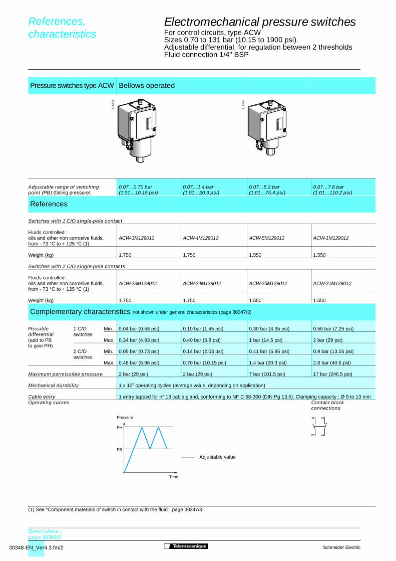
30348-EN_Ver4.3.fm/2 Schneider Electric
MINI
MAXI
8112
93
MINI
MAXI
8112
94
PH
PB
12
34
Electromechanical pressure switches 4
For control circuits, type ACWSizes 0.70 to 131 bar (10.15 to 1900 psi). Adjustable differential, for regulation between 2 thresholds Fluid connection 1/4" BSP
Switches with 2 C/O single-pole contacts
(1) See “Component materials of switch in contact with the fluid”, page 30347/3.
Pressure switches type ACW Bellows operated
Adjustable range of switching 0.07…0.70 bar 0.07…1.4 bar 0.07…5.2 bar 0.07…7.6 barpoint (PB) (falling pressure) (1.01…10.15 psi) (1.01…20.3 psi) (1.01…75.4 psi) (1.01…110.2 psi)
References
Switches with 1 C/O single-pole contact
Fluids controlled : oils and other non corrosive fluids, ACW-3M129012 ACW-4M129012 ACW-5M129012 ACW-1M129012from - 73 °C to + 125 °C (1)
Weight (kg) 1.750 1.750 1.550 1.550
Fluids controlled : oils and other non corrosive fluids, ACW-23M129012 ACW-24M129012 ACW-25M129012 ACW-21M129012from - 73 °C to + 125 °C (1)
Weight (kg) 1.750 1.750 1.550 1.550
Complementary characteristics not shown under general characteristics (page 30347/3)
Possible 1 C/O Min. 0.04 bar (0.58 psi) 0.10 bar (1.45 psi) 0.30 bar (4.35 psi) 0.50 bar (7.25 psi)differential switches(add to PB Max. 0.34 bar (4.93 psi) 0.40 bar (5.8 psi) 1 bar (14.5 psi) 2 bar (29 psi)to give PH) 2 C/O Min. 0.05 bar (0.73 psi) 0.14 bar (2.03 psi) 0.41 bar (5.95 psi) 0.9 bar (13.05 psi)
switchesMax. 0.48 bar (6.96 psi) 0.70 bar (10.15 psi) 1.4 bar (20.3 psi) 2.8 bar (40.6 psi)
Maximum permissible pressure 2 bar (29 psi) 2 bar (29 psi) 7 bar (101.5 psi) 17 bar (246.5 psi)
Mechanical durability 1 x 10⁶ operating cycles (average value, depending on application)
Cable entry 1 entry tapped for n° 13 cable gland, conforming to NF C 68-300 (DIN Pg 13.5). Clamping capacity : Ø 9 to 13 mmOperating curves Contact block
connections
References, characteristics 0
Dimensions :page 30349/2
Adjustable value
Pressure
Time
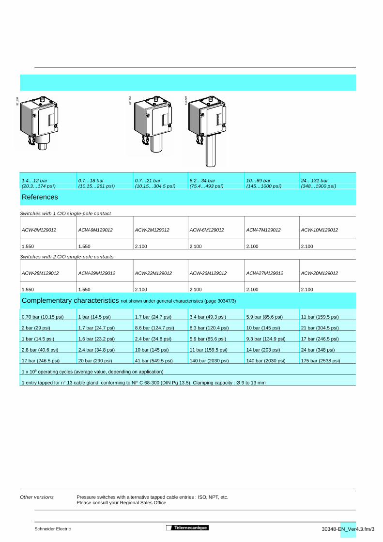
30348-EN_Ver4.3.fm/3Schneider Electric
MINI
MAXI
8112
94
MINI
MAXI
8112
98
MINI
MAXI
8112
99
4
Switches with 1 C/O single-pole contact
Switches with 2 C/O single-pole contacts
1.4…12 bar 0.7…18 bar 0.7…21 bar 5.2…34 bar 10…69 bar 24…131 bar(20.3…174 psi) (10.15…261 psi) (10.15…304.5 psi) (75.4…493 psi) (145…1000 psi) (348…1900 psi)
References
ACW-8M129012 ACW-9M129012 ACW-2M129012 ACW-6M129012 ACW-7M129012 ACW-10M129012
1.550 1.550 2.100 2.100 2.100 2.100
ACW-28M129012 ACW-29M129012 ACW-22M129012 ACW-26M129012 ACW-27M129012 ACW-20M129012
1.550 1.550 2.100 2.100 2.100 2.100
Complementary characteristics not shown under general characteristics (page 30347/3)
0.70 bar (10.15 psi) 1 bar (14.5 psi) 1.7 bar (24.7 psi) 3.4 bar (49.3 psi) 5.9 bar (85.6 psi) 11 bar (159.5 psi)
2 bar (29 psi) 1.7 bar (24.7 psi) 8.6 bar (124.7 psi) 8.3 bar (120.4 psi) 10 bar (145 psi) 21 bar (304.5 psi)
1 bar (14.5 psi) 1.6 bar (23.2 psi) 2.4 bar (34.8 psi) 5.9 bar (85.6 psi) 9.3 bar (134.9 psi) 17 bar (246.5 psi)
2.8 bar (40.6 psi) 2.4 bar (34.8 psi) 10 bar (145 psi) 11 bar (159.5 psi) 14 bar (203 psi) 24 bar (348 psi)
17 bar (246.5 psi) 20 bar (290 psi) 41 bar (549.5 psi) 140 bar (2030 psi) 140 bar (2030 psi) 175 bar (2538 psi)
1 x 10⁶ operating cycles (average value, depending on application)
1 entry tapped for n° 13 cable gland, conforming to NF C 68-300 (DIN Pg 13.5). Clamping capacity : Ø 9 to 13 mm
Other versions Pressure switches with alternative tapped cable entries : ISO, NPT, etc.Please consult your Regional Sales Office.
00
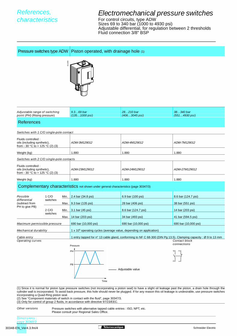
30348-EN_Ver4.3.fm/4 Schneider Electric
MINI
MAXI
8113
00
PH
PB
12
34
Electromechanical pressure switches 4
For control circuits, type ADWSizes 69 to 340 bar (1000 to 4930 psi)Adjustable differential, for regulation between 2 thresholds Fluid connection 3/8" BSP
Switches with 1 C/O single-pole contact
Switches with 2 C/O single-pole contacts
(1) Since it is normal for piston type pressure switches (not incorporating a piston seal) to have a slight oil leakage past the piston, a drain hole through thecylinder wall is incorporated. To avoid back pressure, this hole should never be plugged. If for any reason this oil leakage is undesirable, use pressure switchesincorporating a Quad-Ring piston seal.(2) See “Component materials of switch in contact with the fluid”, page 30347/3.(3) Only for control of group 2 fluids, in accordance with directive 97/23/EEC.
Pressure switches type ADW Piston operated, with drainage hole (1)
Adjustable range of switching 9.3…69 bar 28…210 bar 38…340 barpoint (PH) (Rising pressure) (135…1000 psi) (406…3045 psi) (551…4930 psi)
References
Fluids controlled : oils (including synthetic), ADW-3M129012 ADW-4M129012 ADW-7M129012from - 30 °C to + 125 °C (2) (3)
Weight (kg) 1.880 1.880 1.880
Fluids controlled : oils (including synthetic), ADW-23M129012 ADW-24M129012 ADW-27M129012from - 30 °C to + 125 °C (2) (3)
Weight (kg) 1.880 1.880 1.880
Complementary characteristics not shown under general characteristics (page 30347/3)
Possible 1 C/O Min. 2.4 bar (34.8 psi) 6.9 bar (100 psi) 8.6 bar (124.7 psi)differential switches(subtract from Max. 9.3 bar (135 psi) 28 bar (406 psi) 38 bar (551 psi)PH to give PB) 2 C/O Min. 3.1 bar (45 psi) 8.6 bar (124.7 psi) 14 bar (203 psi)
switchesMax. 14 bar (203 psi) 34 bar (493 psi) 41 bar (594.5 psi)
Maximum permissible pressure 690 bar (10,000 psi) 690 bar (10,000 psi) 690 bar (10,000 psi)
Mechanical durability 1 x 10⁶ operating cycles (average value, depending on application)
Cable entry 1 entry tapped for n° 13 cable gland, conforming to NF C 68-300 (DIN Pg 13.5). Clamping capacity : Ø 9 to 13 mmOperating curves Contact block
connections
Other versions Pressure switches with alternative tapped cable entries : ISO, NPT, etc.Please consult your Regional Sales Office.
References, characteristics 0
Dimensions :page 30349/3
Time
Adjustable value
Pressure

30348-EN_Ver4.3.fm/5Schneider Electric
MINI
MAXI
8113
04
PH
PB
12
34
Electromechanical pressure switches 4
For control circuits, type ADWSizes 69 to 340 bar (1000 to 4930 psi)Adjustable differential, for regulation between 2 thresholds Fluid connection 3/8" BSP
Switches with 1 C/O single-pole contact
Switches with 2 C/O single-pole contacts
(1) See “Component materials of switch in contact with the fluid”, page 30347/3.(2) Only for control of group 2 fluids, in accordance with directive 97/23/EEC.
Pressure switches type ADW Piston operated, with Quad-Ring piston seal
Adjustable range of switching 9.3…69 bar 28…210 bar 38…340 barpoint (PH) (Falling pressure) (135…1000 psi) (406…3045 psi) (551…4930 psi)
References
Fluids controlled : oils and other fluids, ADW-5M129012 ADW-6M129012 ADW-7S1M129012from - 25 °C to + 120 °C (1) (2)
Weight (kg) 1.880 1.880 1.880
Fluids controlled : oils and other fluids, ADW-25M129012 ADW-26M129012 ADW-27S1M129012from - 25 °C to + 120 °C (1) (2)
Weight (kg) 1.880 1.880 1.880
Complementary characteristics not shown under general characteristics (page 30347/3)
Possible 1 C/O Min./max. at 4.8/6.9 bar (69.6/100 psi) 14/21 bar (203/304.5 psi) 19/25 bar (275.5/362.5 psi)differential switches bottom of range(subtract from PH Min./max. at 8.6/10 bar (124.7/145 psi) 28/34 bar (406/493 psi) 38/45 bar (551/652.5 psi)to give PB) top of range
2 C/O Min./max. at 6.2/7.9 bar (89.9/114.6 psi) 17/24 bar (246.5/348 psi) 22/28 bar (319/406 psi)switches bottom of range
Min./max. at 10/12 bar (145/174 psi) 34/39 bar (493/565.5 psi) 44/50 bar (638/725 psi)top of range
Maximum permissible pressure 690 bar (10,000 psi) 690 bar (10,000 psi) 690 bar (10,000 psi)
Mechanical durability 1 x 10⁶ operating cycles (average value, depending on application)
Cable entry 1 entry tapped for n° 13 cable gland, conforming to NF C 68-300 (DIN Pg 13.5). Clamping capacity : Ø 9 to 13 mmOperating curves Contact block
connections
Other versions Pressure switches with alternative tapped cable entries : ISO, NPT, etc.Please consult your Regional Sales Office.
References, characteristics (continued) 0
Dimensions :page 30349/3
Time
Adjustable value
Pressure

30349-EN_Ver2.3.fm/2 Schneider Electric
������������
������������
31
31
68
699,
59,
5
31
31
(1)
18
6988
1788
190
9,5 9,5
������������
������������
31
31
68
699,
59,
5
31
31
(1)
18
6988
1788
167
9,5 9,5
������������
������������
31
31
699,
59,
5
31
31
(1)
69
1788
221
9,5 9,5
������������
������������
31
31
68
699,
59,
5
31
31
(1)
18
6988
1788
173
9,5 9,5
Electromechanical pressure switches 4
For control circuits, type ACW
ACW-3, 4, 23, 24 ACW-1, 5, 8, 9, 21, 25, 28, 29
(1) Tapped entry for n° 13 cable gland (1) Tapped entry for n° 13 cable glandØ : G 1/4 (BSP female) Ø : G 1/4 (BSP female)
ACW-2, 22 ACW-6, 7, 10, 26, 27, 20
(1) Tapped entry for n° 13 cable gland (1) Tapped entry for n° 13 cable glandØ : G 1/4 (BSP female) Ø : G 1/4 (BSP female)
Dimensions 0
Characteristics : page 30347/3, 30348/2
and 30348/3References :
pages 30348/2 and 30348/3
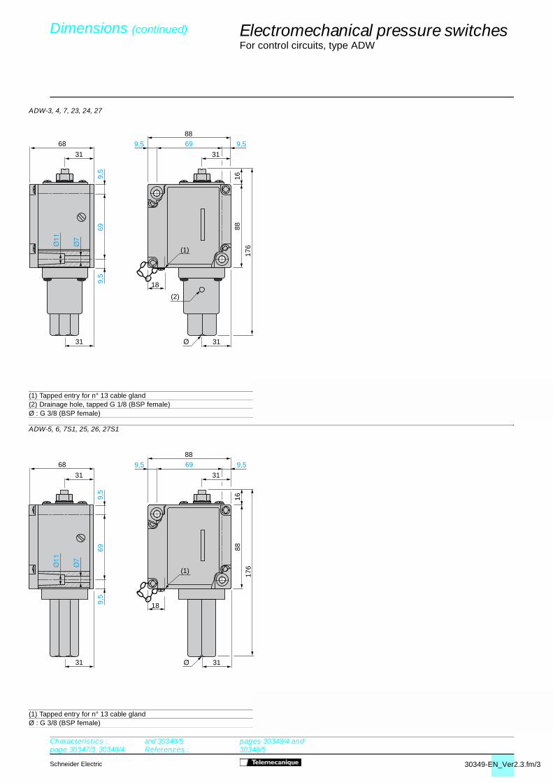
30349-EN_Ver2.3.fm/3Schneider Electric
������������
������������31
31
68
699,
59,
5
31
31
(1)
18
6988
1688
176
9,5 9,5
������������
������������
31
31
68
699,
59,
5
31
31
(1)
18
6988
1688
176
9,5 9,5
(2)
Electromechanical pressure switches 4
For control circuits, type ADW
ADW-3, 4, 7, 23, 24, 27
(1) Tapped entry for n° 13 cable gland(2) Drainage hole, tapped G 1/8 (BSP female)Ø : G 3/8 (BSP female)
ADW-5, 6, 7S1, 25, 26, 27S1
(1) Tapped entry for n° 13 cable glandØ : G 3/8 (BSP female)
Dimensions (continued) 0
Characteristics : page 30347/3, 30348/4
and 30348/5References :
pages 30348/4 and 30348/5

30383-EN_Ver2.3.fm/2 Schneider Electric
12
Electromechanical pressure switches 4
For control circuits, types XMX and XMA
Pressure switches type XMX and XMA are switches for control circuits, with an adjustable differential.They are used to control the pressure of water and air, up to 25 bar.
Location of setting screw
Pressure switches type XMX have an internal setting screw, only accessible after removing the cover.Pressure switches type XMA have an external setting screw, accessible without removing the cover.
Case
Pressure switches type XMX have a black opaque case.Pressure switches type XMA can have a transparent case or a black opaque case.
When setting XMX or XMA pressure switches, adjust the switching pointon rising pressure (PH) first and then the switching point on fallingpressure (PB).
Switching point on rising pressureThe switching point on rising pressure (PH) is set by adjusting screw-nut1.
Switching point on falling pressureThe switching point on falling pressure (PB) is set by adjusting screw-nut2.
Functions
Equipment fitted to various models
Setting
Presentation 0
References :pages 30384/2 and 30384/
3Dimensions :
page 30385/3

30383-EN_Ver2.3.fm/3Schneider Electric
Electromechanical pressure switches 4
For control circuits, types XMX and XMA
Environment characteristics
Conforming to standards e, IEC/EN 60947-5-1
Product certifications UL, CSA (pending)
Protective treatment “TC”
Ambient air temperature °C Operation : - 25…+ 70. Storage : - 40…+ 70
Fluids controlled Air, fresh water, sea water (0…+ 70 °C)
Materials Case : polycarbonate impregnated with Lexan 500R fibre glass (black opaque cover) or polycarbonate impregnated with Lexan 123 fibre glass (transparent cover).Component materials in contact with fluid : chromated zinc alloy (fluid entry), canvas covered nitrile (diaphragm)
Operating position All positions
Electric shock protection Class I conforming to IEC 536
Degree of protection IP 54 conforming to IEC/EN 60529
Operating rate Op. 600cycles/min.
Repeat accuracy < 3.5 %
Fluid connections G 1/4 or 4 x G 1/4 (BSP female) conforming to NF E 03-005, ISO 228
Electrical connections Screw terminals. 2 tapped entries for n° 13 cable gland (DIN Pg 13.5)
Contact block characteristics
Rated operational characteristics a AC-15, B300 (Ue = 240 V, Ie = 1.5 A ; Ue = 120 V, Ie = 3 A) c DC-13, R300 (Ue = 250 V, Ie = 0.1 A)
Rated insulation voltage V Ui = 500, conforming to IEC/EN 60947-1
Rated impulse withstand voltage kV U imp = 6 conforming to IEC/EN 60947-1
Contact operation 1 C/O single-pole contact, snap action
Terminal referencing Conforming to CENELEC EN 50013
Short-circuit protection 10 A cartridge fuse type gG (gI)
Cabling Screw clamp terminals. Clamping capacity, min. : 1 x 1 mm2, max. : 2 x 2.5 mm2
Electrical durability a.c. supply 50/60 Hz, Ith = 10 A Inductive circuit, utilisation category AC-15, 3 A/240 V : 1 million operating cycles
Characteristics 0
References :pages 30384/2 and 30384/
3Dimensions :
page 30385/3
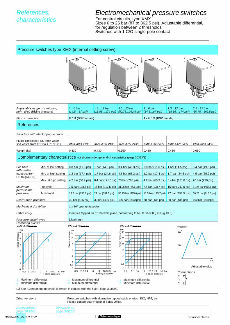
30384-EN_Ver3.2.fm/2 Schneider Electric
PH
PB
5 10 15
15
0
20
25
30
10
25 300,1 20,5
1
3,5
bar
bar
2
1 2 3
3
0
4
5
6
1
2
4 60,2 1,8 4,8
21
bar
bar
bar2 4 6
6
0
8
10
12
2
4
8 100,3 3,6 10,3
2
1
1,3
bar
1314 22
21
8117
82
8117
83
8117
84
8117
83
References, characteristics 0
Time
Adjustable value
Pressure
1 Maximum differential2 Minimum differential
1 Maximum differential2 Minimum differential
Electromechanical pressure switches 4
For control circuits, type XMXSizes 6 to 25 bar (87 to 362.5 psi). Adjustable differential, for regulation between 2 thresholds Switches with 1 C/O single-pole contact
Switches with black opaque cover
(1) See “Component materials of switch in contact with the fluid”, page 30383/3.
Pressure switches type XMX (internal setting screw)
Adjustable range of switching 1…6 bar 1.3…12 bar 3.5…25 bar 1…6 bar 1.3…12 bar 3.5…25 bar point (PH) (Rising pressure) (14.5…87 psi) (18.85…174 psi) (50.75…362.5 psi) (14.5…87 psi) (18.85…174 psi) (50.75…362.5 psi)
Fluid connection G 1/4 (BSP female) 4 x G 1/4 (BSP female)
References
Fluids controlled : air, fresh water, sea water, from 0 °C to + 70 °C (1) XMX-A06L2135 XMX-A12L2135 XMX-A25L2135 XMX-A06L2435 XMX-A12L2435 XMX-A25L2435
Weight (kg) 0.430 0.430 0.650 0.430 0.430 0.650
Complementary characteristics not shown under general characteristics (page 30383/3)
Possible Min. at low setting 0.8 bar (11.6 psi) 1 bar (14.5 psi) 3.4 bar (49.3 psi) 0.8 bar (11.6 psi) 1 bar (14.5 psi) 3.4 bar (49.3 psi)differential(subtract from Min. at high setting 1.2 bar (17.4 psi) 1.7 bar (24.6 psi) 4.5 bar (65.2 psi) 1.2 bar (17.4 psi) 1.7 bar (24.6 psi) 4.5 bar (65.2 psi)PH to give PB)
Max. at high setting 4.2 bar (60.9 psi) 8.4 bar (121.8 psi) 20 bar (290 psi) 4.2 bar (60.9 psi) 8.4 bar (121.8 psi) 20 bar (290 psi)
Maximum Per cycle 7.5 bar (108.7 psi) 15 bar (217.5 psi) 31.25 bar (453.1 psi) 7.5 bar (108.7 psi) 15 bar ( 217.5 psi) 31.25 bar (453.1 psi)permissiblepressure Accidental 13.5 bar (195.7 psi) 27 bar (391.5 psi) 56.25 bar (815.6 psi) 13.5 bar (195.7 psi) 27 bar (391.5 psi) 56.25 bar (815.6 psi)
Destruction pressure 30 bar (435 psi) 30 bar (435 psi) 100 bar (1450 psi) 30 bar (435 psi) 30 bar (435 psi) 100 bar (1450 psi)
Mechanical durability 1 x 10⁶ operating cycles
Cable entry 2 entries tapped for n° 13 cable gland, conforming to NF C 68-300 (DIN Pg 13.5)
Pressure switch type DiaphragmOperating curvesXMX-A06ppppp XMX-A12ppppp XMX-A25ppppp
Connections
Other versions Pressure switches with alternative tapped cable entries : ISO, NPT, etc.Please consult your Regional Sales Office.
Accessories :page 30385/2
Dimensions :page 30385/3
Falling pressure Falling pressure Falling pressure
Ris
ing
pres
sure
Ris
ing
pres
sure
Ris
ing
pres
sure
1 Maximum differential2 Minimum differential
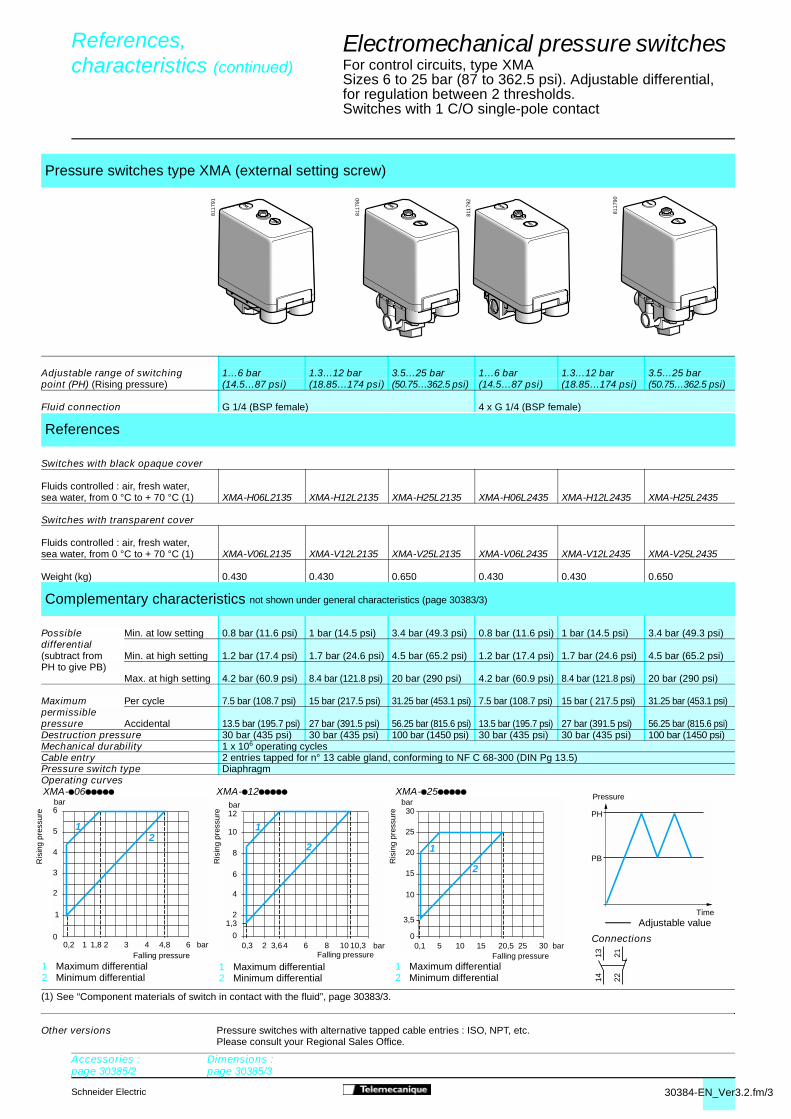
30384-EN_Ver3.2.fm/3Schneider Electric
Adjustable value
1314 22
21
5 10 15
15
0
20
25
30
10
25 300,1 20,5
1
3,5
bar
bar
2
1 2 3
3
0
4
5
6
1
2
4 60,2 1,8 4,8
21
bar
bar
bar2 4 6
6
0
8
10
12
2
4
8 100,3 3,6 10,3
2
1
1,3
barPH
PB
8117
91
8117
90
8117
92
8117
90
Accessories :page 30385/2
Dimensions :page 30385/3
Electromechanical pressure switches 4
For control circuits, type XMASizes 6 to 25 bar (87 to 362.5 psi). Adjustable differential, for regulation between 2 thresholds.Switches with 1 C/O single-pole contact
Switches with black opaque cover
Switches with transparent cover
(1) See “Component materials of switch in contact with the fluid”, page 30383/3.
Pressure switches type XMA (external setting screw)
Adjustable range of switching 1…6 bar 1.3…12 bar 3.5…25 bar 1…6 bar 1.3…12 bar 3.5…25 bar point (PH) (Rising pressure) (14.5…87 psi) (18.85…174 psi) (50.75…362.5 psi) (14.5…87 psi) (18.85…174 psi) (50.75…362.5 psi)
Fluid connection G 1/4 (BSP female) 4 x G 1/4 (BSP female)
References
Fluids controlled : air, fresh water, sea water, from 0 °C to + 70 °C (1) XMA-H06L2135 XMA-H12L2135 XMA-H25L2135 XMA-H06L2435 XMA-H12L2435 XMA-H25L2435
Fluids controlled : air, fresh water, sea water, from 0 °C to + 70 °C (1) XMA-V06L2135 XMA-V12L2135 XMA-V25L2135 XMA-V06L2435 XMA-V12L2435 XMA-V25L2435
Weight (kg) 0.430 0.430 0.650 0.430 0.430 0.650
Complementary characteristics not shown under general characteristics (page 30383/3)
Possible Min. at low setting 0.8 bar (11.6 psi) 1 bar (14.5 psi) 3.4 bar (49.3 psi) 0.8 bar (11.6 psi) 1 bar (14.5 psi) 3.4 bar (49.3 psi)differential(subtract from Min. at high setting 1.2 bar (17.4 psi) 1.7 bar (24.6 psi) 4.5 bar (65.2 psi) 1.2 bar (17.4 psi) 1.7 bar (24.6 psi) 4.5 bar (65.2 psi)PH to give PB) Max. at high setting 4.2 bar (60.9 psi) 8.4 bar (121.8 psi) 20 bar (290 psi) 4.2 bar (60.9 psi) 8.4 bar (121.8 psi) 20 bar (290 psi)
Maximum Per cycle 7.5 bar (108.7 psi) 15 bar (217.5 psi) 31.25 bar (453.1 psi) 7.5 bar (108.7 psi) 15 bar ( 217.5 psi) 31.25 bar (453.1 psi)permissiblepressure Accidental 13.5 bar (195.7 psi) 27 bar (391.5 psi) 56.25 bar (815.6 psi) 13.5 bar (195.7 psi) 27 bar (391.5 psi) 56.25 bar (815.6 psi)Destruction pressure 30 bar (435 psi) 30 bar (435 psi) 100 bar (1450 psi) 30 bar (435 psi) 30 bar (435 psi) 100 bar (1450 psi) Mechanical durability 1 x 10⁶ operating cyclesCable entry 2 entries tapped for n° 13 cable gland, conforming to NF C 68-300 (DIN Pg 13.5)Pressure switch type DiaphragmOperating curvesXMA-p06ppppp XMA-p12ppppp XMA-p25ppppp
Connections
Other versions Pressure switches with alternative tapped cable entries : ISO, NPT, etc.Please consult your Regional Sales Office.
References, characteristics (continued) 0
Falling pressureFalling pressure1 Maximum differential2 Minimum differential
1 Maximum differential2 Minimum differential
1 Maximum differential2 Minimum differential
Falling pressure
Pressure
Time
Ris
ing
pres
sure
Ris
ing
pres
sure
Ris
ing
pres
sure

30385-EN_Ver2.3.fm/2 Schneider Electric
Electromechanical pressure switches 4
For control circuits, types XMX and XMAAccessories and replacement parts
Description Reference Weightkg
Fixing bracket XMA-ZL001 0.035
Knurled adjustment knob, Ø 36 mm XML-ZL003 0.010fits over adjustment screws to facilitatesetting
N° 13 plastic cable gland With anti pull-out ring DE9-PM1201 0.005(for cable Ø 6…9 mm)
Without anti pull-out ring DE9-PM1202 0.005(for cable Ø 6…9 mm)
With anti pull-out ring DE9-PM1203 0.005(for cable Ø 9…12.5 mm)
Without anti pull-out ring DE9-PM1204 0.005(for cable Ø 9…12.5 mm)
Description For pressure switch Reference Weightkg
Diaphragms Size 6 bar XMP-Z31 0.005
Size 12 bar XMP-Z32 0.005
Size 25 bar XMP-Z33 0.005
References 0
DE9-PM1201
DE9-PM1202
XMA-ZL001
XML-ZL003
XMP-Z3p
Dimensions :page 30385/3

30385-EN_Ver2.3.fm/3Schneider Electric
A
r = 63 (2)
106
30,5
=
57
=
XM
A :
7
r = 63 (2)
D
C
B
106
30,5
=
57
=43,5
58
97,5
(1)
XM
A :
7
A
43,5
58
97,5
(1)
126
30,5
=
57
=
AC
D
B
r = 63 (2)
XM
A :
7
Electromechanical pressure switches 4
For control circuits, types XMX and XMA
XMX-A06L2135, XMX-A12L2135 XMX-A06L2435, XMX-A12L2435XMA-p06L2135, XMA-p12L2135 XMA-p06L2435, XMA-p12L2435
ØA = G 1/4 (BSP female) ØA = ØB = ØC = ØD = G 1/4 (BSP female)(1) 2 tapped entries for n° 13 cable gland (1) 2 tapped entries for n° 13 cable gland(2) Minimum clearance zone for screwing-on pressure switch at point A (2) Minimum clearance zone for screwing-on pressure switch at point A XMX-A25L2135, XMX-A25L2435 Fixing bracketXMA-p25L2135, XMA-p25L2435 XMA-ZL001
XMp-p25L2135 : ØA only = G 1/4 (BSP female)XMp-p25L2435 : ØA = ØB = ØC = ØD = G 1/4 (BSP female)(1) 2 tapped entries for n° 13 cable gland (2) Minimum clearance zone for screwing-on pressure switch at point A
Dimensions 0
Characteristics :page 30383/3 to 30384/3
References : pages 30384/2 and
30384/3

30371-EN_Ver3.3.fm/2 Schneider Electric
1314 12
111314 12
11
1 2 1 2
PH2
PH1
PB1
PB2
1 2 43 1 2 43
1314 12
111314 12
11
2324 22
211314 12
11
2324 22
211314 12
11
1 2 1 2
2324 22
211314 12
11
2324 22
211314 12
11PH
PB
PH
PB
Electromechanical pressure and vacuum switches 4
Nautilus®
The function of pressure and vacuum switches is the control or regulation of pressure or vacuum levels inhydraulic or pneumatic systems.They transform the pressure change into an electrical signal and when a preset pressure or vacuum is reached,the output contact of the switch changes state.
Switches with power electrical contacts, either 2-pole or 3-pole, designed fordirect switching of single-phase or 3-phase motors (pumps, compressors,etc.).
Switches with standard electrical contacts, designed for control of contactors,relays, power valves, PLC inputs, etc.
The switches for detection of a single threshold (fixed differential) have asingle adjustable setting point (PH).The differential between the high and low points (PH - PB) depends upon thenatural characteristics of the switch. It is not adjustable.
The switches for regulation between 2 thresholds (adjustable differential)have both a high point setting (PH) and a low point setting (PB). Both ofthese points can be independently adjusted.
The dual stage switches, for detection at each threshold, have an adjustablehigh point setting for each stage (PH1 and PH2). Both of these points can beindependently adjusted.
General 0
Time
Adjustable valueNon adjustable value
Pressure
PH = High pointPB = Low point
Adjustable valueNon adjustable value
Time
Fixed differ-ential
Fixed differential
3
Example: contact schematics of XML-A
1 2
Switches forpower circuits
Switches forcontrol circuits
Function
Pressure switchoperating principle
Detectionof a singlethreshold
Detection of2 thresholds
Regulationbetween 2thresholds
Pressure
Fixed differential
PH = High pointPB = Low point
Pressure
Time
Adjustable differential
Example:contact schematics for XML-B
1 2
Adjustable value
PH = High pointPB = Low point
Adjustable spread
Example:contact schematics of XML-D
2
4
1
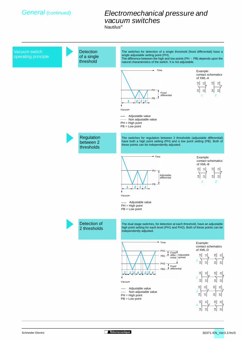
30371-EN_Ver3.3.fm/3Schneider Electric
1314 12
11
1314 12
11
1 2 1 2
1 2 1 2
1314 12
11
1314 12
11
PH1
PH2
PB2
PB1
1 2 43 1 2 43 1314 12
11 2324 22
21
2324 22
211314 12
11
2324 22
211314 12
11
1314 12
11 2324 22
21
Electromechanical pressure and vacuum switches 4
Nautilus®
The switches for detection of a single threshold (fixed differential) have asingle adjustable setting point (PH).The difference between the high and low points (PH - PB) depends upon thenatural characteristics of the switch. It is not adjustable.
The switches for regulation between 2 thresholds (adjustable differential)have both a high point setting (PH) and a low point setting (PB). Both ofthese points can be independently adjusted.
The dual stage switches, for detection at each threshold, have an adjustablehigh point setting for each level (PH1 and PH2). Both of these points can beindependently adjusted.
General (continued) 0
Vacuum switchoperating principle
Detectionof a singlethreshold
PH = High pointPB = Low point
Adjustable value- - - - Non adjustable value
PH = High pointPB = Low point
Adjustable value
PH
PB
Vacuum
Time
PH
PB
Vacuum
Time
Adjustable differential
Adjustable spread
Detection of2 thresholds
Example: contact schematics of XML-D
2
3
4
1
PH = High pointPB = Low point
Adjustable valueNon adjustable value
Fixed differ-ential
Fixed differential
Example: contact schematics of XML-A
1 2
Example: contact schematics of XML-B
1 2
Vacuum
Time
Fixed differential
Regulationbetween 2thresholds

30371-EN_Ver3.3.fm/4 Schneider Electric
Differential
+
–
Electromechanical pressure and vacuum switches 4
Nautilus®
The difference between the minimum low point (PB) and the maximum highpoint (PH) setting values.
Pressure switches and vacuum-pressure switches (vacu-pressureswitches)Maximum value of the operating range.Vacuum switchesMinimum value of the operating range.
Pressure switchesThe upper pressure setting at which the pressure switch will actuate thecontacts on rising pressure. Vacuum switchesThe lower vacuum setting at which the vacuum switch will reset the contactson rising pressure.
The pressure at which the switch output changes state on falling pressure.
Switches with fixed differentialThe lower point (PB) is not adjustable and is entirely dependent on the highpoint setting (PH) and the natural differential of the switch.
Switches with adjustable differentialThe adjustable differential enables the independent setting of the lower point(PB).
The difference between the switching point on rising pressure (PH) and theswitching point on falling pressure (PB).
For dual stage switches, the spread indicates the difference between the 2switching points on rising pressure (PH2 and PH1) and, for vacuum switches,the difference between the 2 switching points on falling pressure (PB2 andPB1).
The tolerance between the point atwhich the switch actuates its contactsand the value indicated on the settingscale. Where very high setting accura-cy is required, it is recommended touse separate measuring equipment(pressure gauge, etc.).
General (continued) 0
Switching pointon rising pressure(PH)
Switching pointon falling pressure(PB)
Size
Setting point
Accuracy(switches with setting scale)
Terminology Operating range
Spread
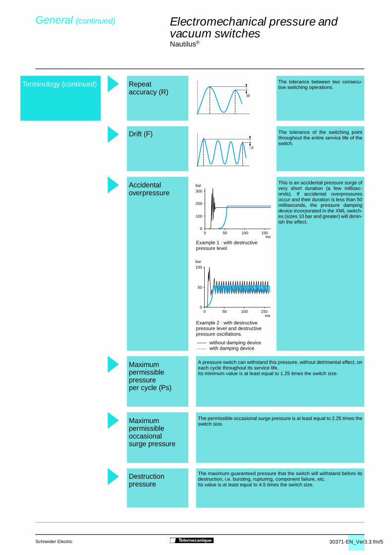
30371-EN_Ver3.3.fm/5Schneider Electric
F
R
300bar
200
100
00 50 100 150
ms
0 50 100 1500
50
100bar
ms
Electromechanical pressure and vacuum switches 4
Nautilus®
The tolerance between two consecu-tive switching operations.
The tolerance of the switching pointthroughout the entire service life of theswitch.
This is an accidental pressure surge ofvery short duration (a few millisec-onds). If accidental overpressuresoccur and their duration is less than 50milliseconds, the pressure dampingdevice incorporated in the XML switch-es (sizes 10 bar and greater) will dimin-ish the effect.
A pressure switch can withstand this pressure, without detrimental effect, oneach cycle throughout its service life. Its minimum value is at least equal to 1.25 times the switch size.
The permissible occasional surge pressure is at least equal to 2.25 times theswitch size.
The maximum guaranteed pressure that the switch will withstand before itsdestruction, i.e. bursting, rupturing, component failure, etc.Its value is at least equal to 4.5 times the switch size.
General (continued) 0
Maximumpermissiblepressureper cycle (Ps)
Maximumpermissibleoccasionalsurge pressure
Destructionpressure
Repeataccuracy (R)
Drift (F)
Accidentaloverpressure
Example 1 : with destructive pressure level.
Example 2 : with destructive pressure level and destructive pressure oscillations.
without damping devicewith damping device
Terminology (continued)

30371-EN_Ver3.3.fm/6 Schneider Electric
Pressureswitches Application range
XML-A/B/C/D,XMX, XMA
XML-E
5
6
10
8
20
60
100
15
150
200
500
120
240
24
V
48
1 mA 2 mA 3 mA 6 mA 10 mA 2 A 3 A 6 A 10 A 1 A
1
2
3
4
I1,5 A
Hea
ting
limit
Ithe
Electromechanical pressure and vacuum switches 4
Nautilus®
On standard loads
Continuous duty, frequent switching
Insulation voltage limit
1 Standard PLC input, type 12 Standard PLC input, type 23 Switching capacity conforming to IEC
4 Switching capacity conforming to IEC
PLC : Programmable Logic Controller
On small loads
The use of electromechanical pressure and vacuum switches with programmable logic controllers isbecoming more predominant.On small loads, the reliability of the switches maintain a failure rate of less than 1 for 100 million operatingcycles.
947-5-1, utilisation category AC-15, DC-13B300 240 V 1.5 AR300 250 V 0.1 A
947-5-1, utilisation category AC-15, DC-13B300 120 V 3 AR300 125 V 0.22 A
General (continued) 0
Application range of pressure and vacuum switches types XML, XMA and XMX, for control circuits
Inductive loads

30371-EN_Ver3.3.fm/7Schneider Electric
10 bar
0,6
7 6,5
20 bar
1
7 6
35 bar
1,5
75
45 bar
1
12
2025
80 bar
1,5
12
35
45
20 bar
1
1835 bar
1,5
18
Electromechanical pressure and vacuum switches 4
Nautilus®
After establishing the type of switch required for the application (single threshold detection or regulation between 2thresholds), the selection of its size will depend on the following criteria :- the differential : difference between the high point (PH) and the low point (PB),- the maximum pressure permissible per cycle,- repeat accuracy, precision and minimum drift.
Examples of a fixed differential pressure switch selection, for detection of a single threshold
Example : for a selected high point (PH) of 7 bar
Select an XML-A010ppppp (the lowest size)
Example : for a selected high point (PH) of 12 bar
Select an XML-A035ppppp (the highest size)
Example : for a selected high point (PH) of 18 bar
As a general rule, work-ing at the upper or lowerlimits of the operatingrange should be avoided.
Select an XML-A035ppppp
Example : 1 bar = 14.50 psi = 105 Pa
XML-A010ppppp XML-A020ppppp XML-A035pppppDifferential = 0.5 bar Differential = 1 bar Differential = 2 bar
XML-A020ppppp XML-A035pppppPermissible occasional Permissible occasional surge pressure = 45 bar surge pressure = 80 bar
XML-A020ppppp XML-A035pppppAdjustable, 1 to 20 bar Adjustable, 1.5 to 35 bar
psi kg/cm2 bar atm mm Hg (Torr) mm H2O Pa
psi 1 0.07031 0.06895 0.06805 51.71 703.7 6895
kg/cm2 14.22 1 0.98066 0.96784 735.55 10,000 98,066
bar 14.50 1.0197 1 0.98695 750.06 10,197 105
atm 14.70 1.0333 1.0132 1 760.0 10,333 101,325
mm Hg (Torr) 0.01934 1.360 x 10⁻³ 1.333 x 10⁻³ 1.316 x 10⁻³ 1 13.59 133.3
mm H2O 1.421 x 10⁻³ 10-4 a 10-4 a 10-4 0.07361 1 a 9.80
Pa 1.45 x 10⁻⁴ 1.0197 x 10⁻⁵ 10-5 9.8695 x 10⁻⁶ 7.5 x 10⁻³ 0.10197 1
General (continued) 0
Principle criterion : minimum differential
Principle criterion : tolerance to highoverpressures
Principle criterion :repeat accuracy, precision andminimum drift
Units of pressureconversion table
Selection of switch size

30372-EN_Ver3.3.fm/2 Schneider Electric
Maxi+
–
Mini
00
Rising pressure
Adj
uste
men
t ran
geof
hig
h po
int (
PH
)
Low point (PB)range
Fallingpressure
0
PH
+
– 0
0
PH
+
–
PB
PB0
Falling pressure
Falling pressure
PH
+
–
PB
PB
PH – PB
00
0 28PB
40 60203
20
PH 40
60
0
Falling pressure
bar
bar
Adjustment rangeof the high point
Electromechanical pressure and vacuum switches 4
Fixed differential switches, for detection of a single threshold
Defined by the difference between theminimum and maximum high point (PH)setting values.
For a high set point (PH), the lower point(PB) is fixed and cannot be adjusted.For a low set point (PB), the higher point(PH) is fixed and cannot be adjusted.
The upper pressure setting at which thepressure or vacuum switch will actuate thecontacts on rising pressure.
Adjustable throughout the range on risingpressure.
The pressure at which the switch contactchanges state on falling pressure.
The lower point (PB) is not adjustable andis entirely dependent on the high point(PH) setting and the natural differential ofthe switch.
PH - PB = natural differentialThe difference between the switching pointon rising pressure (PH) and the switchingpoint on falling pressure (PB).
This point is not adjustable and therefore,the value of the differential is fixed. It is the natural differential of the switch(contact differential, friction, etc).
p Consider a switching point on risingpressure (PH) of 40 bar (set value atwhich the contact will change state onrising pressure).p It can be seen that the switching pointon falling pressure (PB) is 28 bar (fixedvalue at which the contact will return toits original state).Conclusion :- The differential will be 40 - 28 = 12 bar.
Operating curves 0
Switching point on rising pressure (PH)
Switching point on falling pressure (PB)
Differential
Example
Falling pressure
Rising pressure
Rising pressure
Rising pressure
Rising pressure
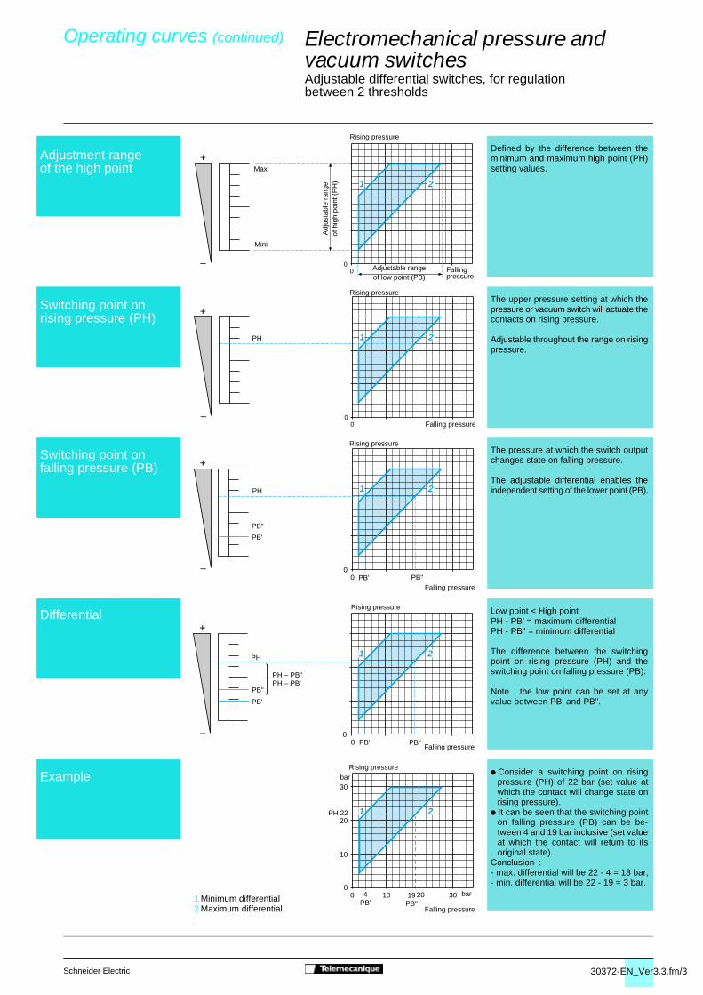
30372-EN_Ver3.3.fm/3Schneider Electric
Maxi
+
–
Mini
00
1 2
Adjustable rangeof low point (PB)
Adj
usta
ble
rang
eof
hig
h po
int (
PH
)
Fallingpressure
+
–0
0
1 2PH
Falling pressure
+
–
PH
PB'
PB'
PB"
PB"00
1 2
Falling pressure
0
+
–
PB'
PB"
PH
PH – PB"PH – PB'
PB' PB"0
1 2
Falling pressure
0
30
20
10
10 20 3019PB"
4PB'
0
1 2PH 22
Falling pressure
bar
Adjustment rangeof the high point
1 Minimum differential2 Maximum differential
Electromechanical pressure and vacuum switches 4
Adjustable differential switches, for regulation between 2 thresholds
Defined by the difference between theminimum and maximum high point (PH)setting values.
The upper pressure setting at which thepressure or vacuum switch will actuate thecontacts on rising pressure.
Adjustable throughout the range on risingpressure.
The pressure at which the switch outputchanges state on falling pressure.
The adjustable differential enables theindependent setting of the lower point (PB).
Low point < High pointPH - PB' = maximum differentialPH - PB" = minimum differential
The difference between the switchingpoint on rising pressure (PH) and theswitching point on falling pressure (PB).
Note : the low point can be set at anyvalue between PB' and PB".
p Consider a switching point on risingpressure (PH) of 22 bar (set value atwhich the contact will change state onrising pressure).
p It can be seen that the switching pointon falling pressure (PB) can be be-tween 4 and 19 bar inclusive (set valueat which the contact will return to itsoriginal state).
Conclusion :- max. differential will be 22 - 4 = 18 bar,- min. differential will be 22 - 19 = 3 bar.
Operating curves (continued) 0
Switching point on rising pressure (PH)
Switching point on falling pressure (PB)
Differential
Example
bar
Rising pressure
Rising pressure
Rising pressure
Rising pressure
Rising pressure
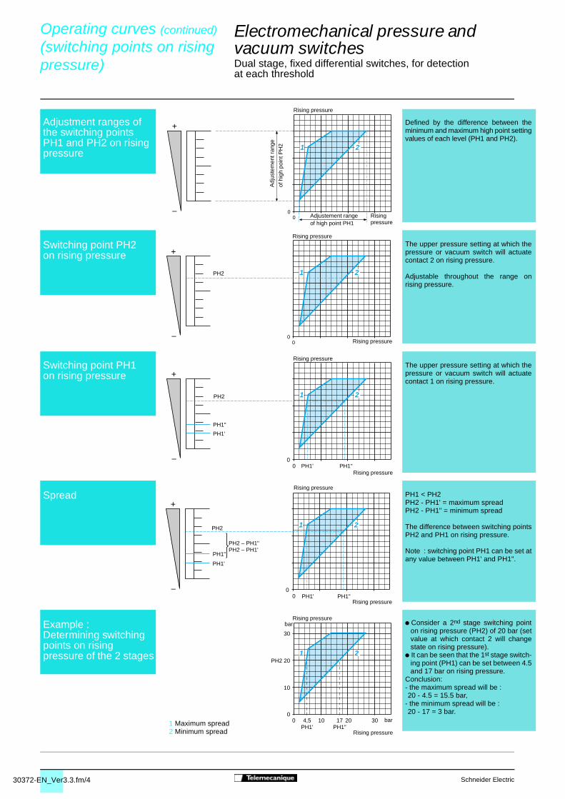
30372-EN_Ver3.3.fm/4 Schneider Electric
+
–0
0
1 2
Adj
uste
men
t ran
ge
of h
igh
poin
t PH
2
Adjustement rangeof high point PH1
Risingpressure
+
–0
0
1 2PH2
Rising pressure
+
–
PH2
PH1'
PH1'
PH1"
PH1"00
1 2
Rising pressure
0
+
–
PH1'
PH1"
PH2
PH2 – PH1"PH2 – PH1'
PH1' PH1"0
1 2
Rising pressure
0
30
PH2 20
10
10 20 3017PH1"
4,5PH1'
0
1 2
Rising pressure
bar
Electromechanical pressure and vacuum switches 4
Dual stage, fixed differential switches, for detection at each threshold
Defined by the difference between theminimum and maximum high point settingvalues of each level (PH1 and PH2).
The upper pressure setting at which thepressure or vacuum switch will actuatecontact 2 on rising pressure.
Adjustable throughout the range onrising pressure.
The upper pressure setting at which thepressure or vacuum switch will actuatecontact 1 on rising pressure.
PH1 < PH2PH2 - PH1' = maximum spreadPH2 - PH1" = minimum spread
The difference between switching pointsPH2 and PH1 on rising pressure.
Note : switching point PH1 can be set atany value between PH1' and PH1".
p Consider a 2nd stage switching pointon rising pressure (PH2) of 20 bar (setvalue at which contact 2 will changestate on rising pressure).
p It can be seen that the 1st stage switch-ing point (PH1) can be set between 4.5and 17 bar on rising pressure.
Conclusion:- the maximum spread will be :
- the minimum spread will be : 20 - 4.5 = 15.5 bar,
20 - 17 = 3 bar.
Operating curves (continued) 0
(switching points on rising pressure) 0
Adjustment ranges of the switching pointsPH1 and PH2 on rising pressure
Switching point PH2 on rising pressure
Switching point PH1 on rising pressure
Spread
Example :Determining switching points on rising pressure of the 2 stages
1 Maximum spread2 Minimum spread
Rising pressure
Rising pressure
Rising pressure
Rising pressure
Rising pressurebar

30372-EN_Ver3.3.fm/5Schneider Electric
Maxi+
–
Mini
00
Adj
uste
men
t ran
geof
hig
h po
int (
PH
)
Rising pressure
Low point (PB)range
Fallingpressure
0
PH
+
–
PB
PB0
Falling pressure
0
PH
+
– 0
Rising pressure
Falling pressure
PH
+
–
PB
PB
PH – PB
00
Falling pressure
0 14PB
20 30103
10
PH 20
30
0E
G
F
H
Falling pressure
bar
bar
Electromechanical pressure and vacuum switches 4
Dual stage, fixed differential switches, for detection at each threshold
Defined by the difference between theminimum and maximum high point (PH1or PH2) setting values for each stage.
For a high set point (PH1 or PH2), thelower point (PB1 or PB2) is fixed andcannot be adjusted.For a low set point (PB1 or PB2), thehigher point (PH1 or PH2) is fixed andcannot be adjusted.
The upper pressure setting at which thepressure or vacuum switch will actuatethe contact, for each stage, on risingpressure.
Adjustable throughout the range onrising pressure.
The pressure at which the switch contactchanges state, for each stage, on fallingpressure.
The lower point (PB) is not adjustableand is entirely dependent on the highpoint (PH) setting and the naturaldifferential of the switch.
PH - PB = natural differentialThe difference between the switchingpoint on rising pressure (PH) and theswitching point on falling pressure (PB),for each stage.
This point is not adjustable and therefore,the value of the differential is fixed. It is the natural differential of the switch(contact differential, friction, etc.) foreach of its 2 stages.
For stage 2 (segment GH) :p Consider a switching point on rising
pressure (PH2) of 20 bar (set value atwhich contact 2 will change state onrising pressure).
p It can be seen that the switching pointon falling pressure (PB2) is 14 bar(fixed value at which contact 2 willreturn to its original state).
Conclusion : for stage 2, the differentialwill be 20 - 14 = 6 bar.Repeat the same procedure for stage 1(segment EF).
Operating curves (continued) 0
(switching points on falling pressure) 0
Switching point on rising pressure(PH1 or PH2)
Switching point on falling pressure(PB1 or PB2)
Differential
Example :stage 1 = segment EFstage 2 = segment GH
Adjustment range of the high point(PH1 or PH2)
Rising pressure
Rising pressure
Rising pressure