Embed Size (px)
Citation preview

Design of an 8X8 Printed Circuit Board
Dipole Phased Array using HFSS
Shu Li AnsoftHsueh-Yuan Pao Lawrence Livermore National
Lab, University of California

• Introduction• Antenna Specifications• Designing the isolated dipole• Designing the arrayed dipole• Results
Outline

Antenna Design Goals
• Objective: build a low cost, high performance, broad band multi-beam with large scan angles print circuit board dipole phased array antenna
• Challenges– Difficult to analyze the dielectric loading effects on the active
impedance and radiation pattern using expansion of ordinary space modes
– Difficult to design the phased array with large scan angles– Difficult to predict antenna blindness due to surface wave

Antenna Specifications• Frequency: 1.71 – 1.99 GHz• Number of Beams: 7 simultaneous multi-beam • Beam Directions: -53º, -32º, -15º, 0º, 15º, 32º, 53º• Antenna Gain:
– 1.71 GHz: 18 dB center beam, 16 dB edge beam – 1.8 GHz: 18.4 dB center beam, 16.4 dB edge beam– 1.9 GHz: 18.8 dB center beam, 16.8 dB edge beam – 1.99 GHz: 19.1 dB center beam, 17.1 dB edge beam
• Azimuth Beamwidth:– 1.71 GHz: 14.5º center beam, 23.4º edge beam – 1.8 GHz: 13.8º center beam, 22.3º edge beam– 1.9 GHz: 13.1º center beam, 21.1º edge beam – 1.99 GHz: 12.5º center beam, 20.1º edge beam
• Elevation Beamwidth: 9º• Polarization: Linear, vertical

Antenna Description
• Substrate: FR-408 (εr = 3.7, loss tangent = 0.01)• Substrate thickness: 0.03”• 8X8 array• Element separation: 0.7λ in elevation, 0.5λ in azimuth
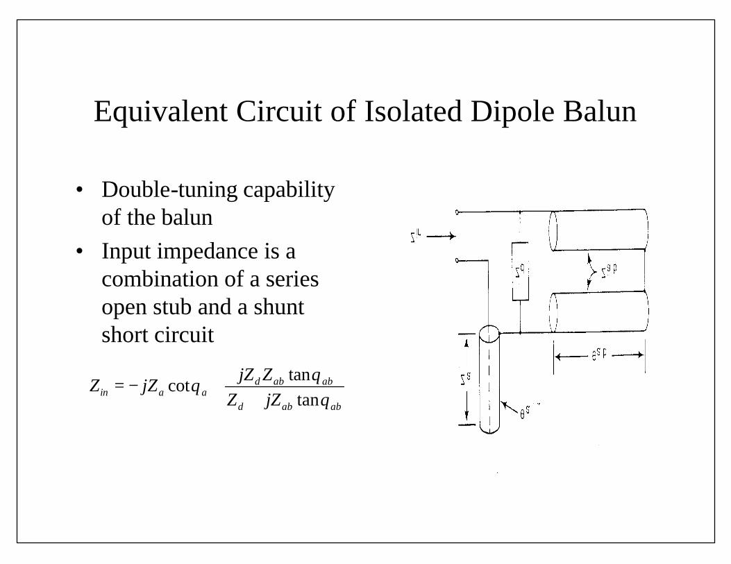
Equivalent Circuit of Isolated Dipole Balun
• Double-tuning capability of the balun
• Input impedance is a combination of a series open stub and a shunt short circuit
tancot
tand ab ab
in a ad ab ab
jZ ZZ jZ
Z jZθ
θθ
= − ++

Model of Broad Band Printed Circuit Board Dipole in HFSS

Comparison of Reflection Coefficient before and after Optimization Design

Set-up Parameters in HFSS Macro
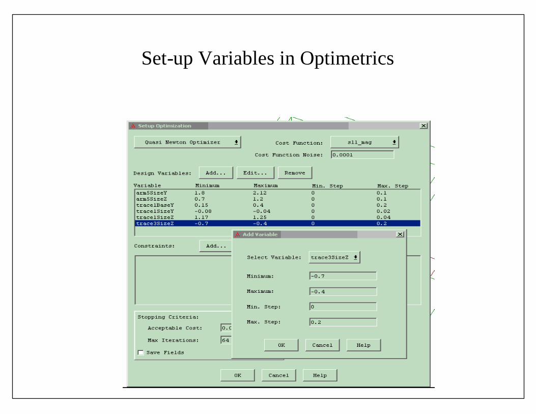
Set-up Variables in Optimetrics

Optimization Output Table

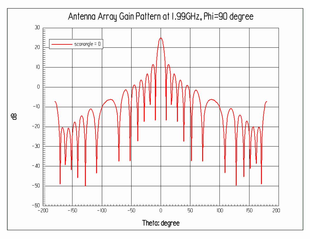
Set-up Scan-angle Parameter

Edit Variables in Optimetrics
Solve fields on 4 frequencies and 7 scan-angles using Optimetrics
7 hours and 30 minutes to run the 4X7=28 simulations


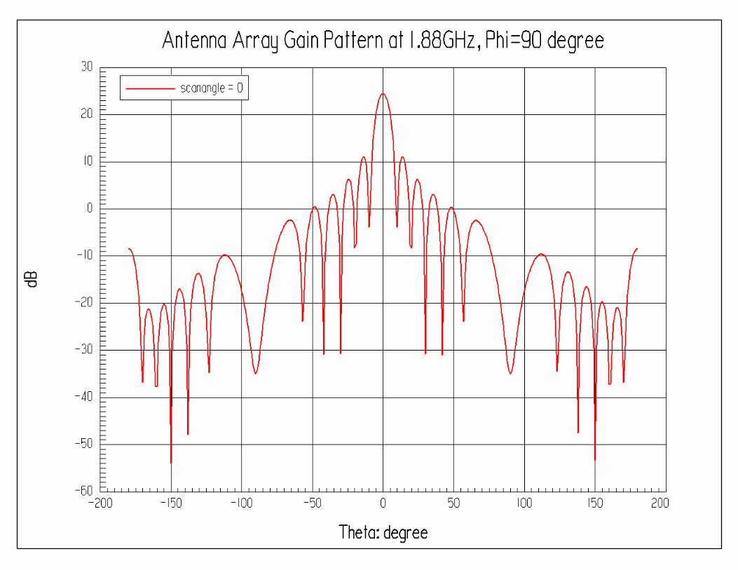
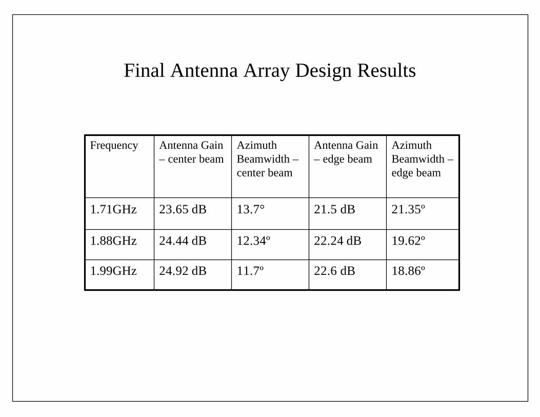
Final Antenna Array Design Results
Azimuth Beamwidth –edge beam
Antenna Gain – edge beam
Azimuth Beamwidth –center beam
Antenna Gain – center beam
Frequency
18.86º22.6 dB11.7º24.92 dB1.99GHz
19.62º22.24 dB12.34º24.44 dB1.88GHz
21.35º21.5 dB13.7°23.65 dB1.71GHz

Conclusion
• Printed Circuit Board Dipole Phased Array —Broad band
• HFSS – accuracy • Optimetics – saving time
best design performance