Embed Size (px)
Citation preview

Summary of Locomotive Aftertreatment Applications
by
John HedrickPrincipal EngineerSouthwest Research Institute®
(210) [email protected]
June 6, 2007
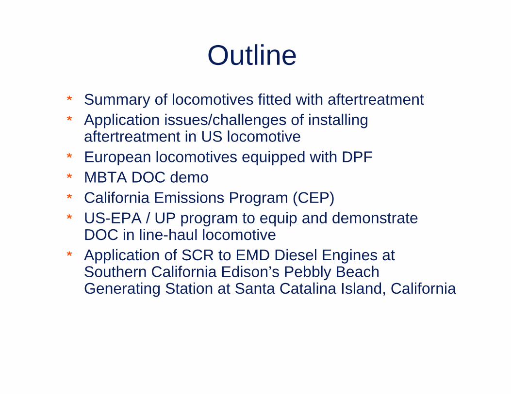
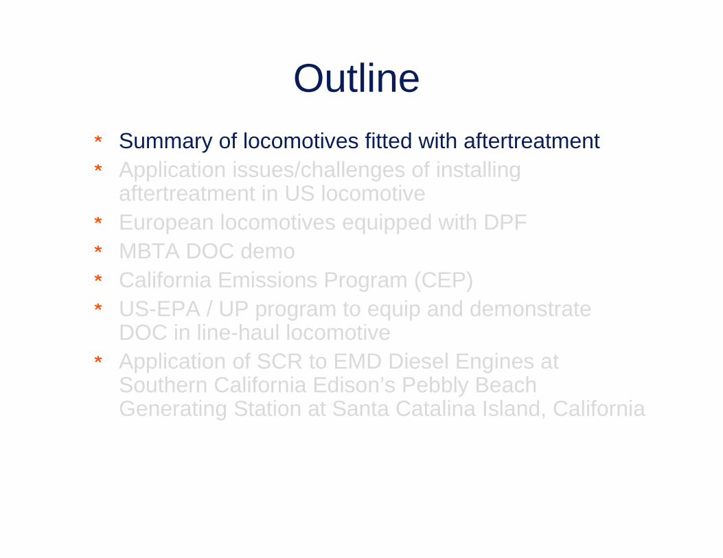
Outline* Summary of locomotives fitted with aftertreatment* Application issues/challenges of installing
aftertreatment in US locomotive* European locomotives equipped with DPF * MBTA DOC demo* California Emissions Program (CEP)* US-EPA / UP program to equip and demonstrate
DOC in line-haul locomotive* Application of SCR to EMD Diesel Engines at
Southern California Edison’s Pebbly Beach Generating Station at Santa Catalina Island, California

Summary of Locomotive Aftertreatment Applications
Europe:* SBB Cargo: Vossloh MaK2000BB + Hug DPF (1)* SBB Cargo: Vossloh Mak 1700 + Hug DPF (75+)* Eurotunnel: Vossloh MaK 1206 + scrubber wagon
» In the process of being retrofitted with Hug DPF & SCR
USA:* MBTA Boston: EMD F40 + Oxycat* UP2368 EMD SD60M + Oxycat* UPY1378 & BNSF3703: EMD MP15DC + Hug DPF
* SCR – None on Locomotives W/ power ratings > 1,000 hp» One case study of SCR on EMD engines

Outline* Summary of locomotives fitted with aftertreatment* Application issues/challenges of installing
aftertreatment in US locomotive* European locomotives equipped with DPF * MBTA DOC demo* California Emissions Program (CEP)* US-EPA / UP program to equip and demonstrate
DOC in line-haul locomotive* Application of SCR to EMD Diesel Engines at
Southern California Edison’s Pebbly Beach Generating Station at Santa Catalina Island, California

Recapping Locomotive AftertreatmentApplication Issues/Challenges
* Packaging and space availability» AAR “Plate L” clearance diagram
* Locomotive specific issues:» Shock & vibration» Temperature extremes» Tunnel operation environment» Railroad lubricating oil considerations
* Locomotive product qualification, verification, and reliability* Locomotive emissions useful life, emissions warranty, etc.* Crankcase blowby considerations
Outline* Summary of locomotives fitted with aftertreatment* Application issues/challenges of installing
aftertreatment in US locomotive* European locomotives equipped with DPF * MBTA DOC demo* California Emissions Program (CEP)* US-EPA / UP program to equip and demonstrate
DOC in line-haul locomotive* Application of SCR to EMD Diesel Engines at
Southern California Edison’s Pebbly Beach Generating Station at Santa Catalina Island, California

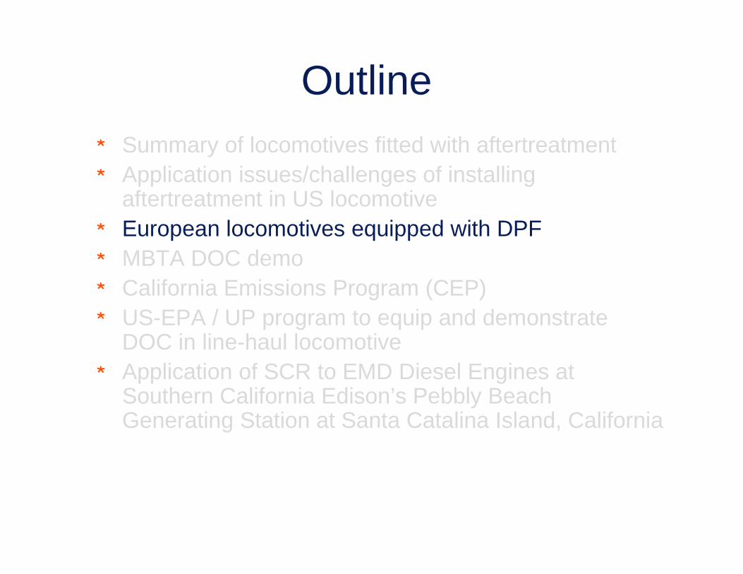
European Locomotives Equipped withDiesel Particulate Filters (DPF)
by
Steve Fritz, P.E.Southwest Research Institute®
(210) [email protected]
and
Mike Iden, P.E.Union Pacific Railroad(708) [email protected]
and
Jennifer AndersonBNSF Railway(206) [email protected]
October 2005

European Locomotive Applications -Background
* Several reports of European diesel locomotives equipped with particulate filters
» 1,500 kW (2,000 hp – GP38 equivalent) Cat-powered diesel-hydraulic freight locomotives
» Also one prototype 2,700 kW (3,600 hp) Vossloh freight locomotive with a MTU 20V-4000 diesel engine
– This prototype is the largest, most powerful diesel powered freight locomotive manufactured today in Europe
* Both equipped with Diesel Particulate Filters (a.k.a. “soot filters”) manufactured by Hug Engineering in Winterthur, Switzerland» Hug is one of the manufacturers participating in the
AAR/BNSF/UP-sponsored “California Emissions Program”» Soot filters installed by the locomotive OEM (Vossloh) on
new locomotives as requested by the customer

Vossloh 2000 Series Locomotive
* 2,700 kW (3,600 hp) MTU 20V-4000 diesel engine
* Hug DPF integrated into car body» Replaced muffler» Very heavy – needed to
factor weight into mounting design
» Designed for 5 g longitudinal shock, and 3 g vertical.
» 2 burners to regenerate filter
* DPF offered today as an option on new locomotives in selected European markets, supported by locomotive and engine OEMs

Comparison of Largest US & European Diesel Freight Locomotives
GE 4400 HP diesel-electric AC locomotive
Vossloh MaK 2000BB 3,600 HP diesel-hydraulic locomotive
420,000 pound weight 76’ long
200,000 pound weight 57’ long
MTU high-speed(1,800 rpm) 3,600 HP
diesel engine
GE Evolution-series medium-speed 4400 HP
diesel engineExhaust muffler
Hug diesel particulate filter (DPF) inside muffler
900 rpm EMD 2-stroke1,050 rpm GE 4-stroke

Swiss Cargo Am843 Locomotives* SBB (Swiss Cargo railroad)
ordered 73 Vossloh (MAK) 1700 Series Locomotives
* Powered by Cat 3512 diesel engine rated at 1,500 kW (2,000 hp)» 1,500 kW is normal US rating for a
3516 engine, e.g., EMD GP20D* SBB Cargo required that all new
locomotives in this order be equipped with “Soot Filters” (DPF)
* Swiss Cat dealer worked with Hug Engineering and Vossloh to integrate DPF
* No in-use emissions testing performed or required
Source: SBB Cargo 2004 Annual Report

Hug DPF Designed Into New Locomotive Carbody
HUG DPF in MAK 1700 car body
Housing for MAK 1700 Locomotive

SBB Cargo - DPF* 73 - MAK 1700 locomotives
delivered to SBB so far» All equipped with Hug DPF
* Initial delivery units had almost 2 year of operating experience» SBB reports no significant
problems with DPF» Hug monitoring backpressure
which indicates need for ash cleaning
» Cat 3512 engines using synthetic, low ash lubrication oil to minimize ash loading of DPF
* No UIC emissions test results performed on engine + DPF
» DPF application voluntary» Actual DPF efficiency unknown
but assumed to be high
Excerpt from SBB Environmental Report
Hug DPF installed in MAK 1700 Locomotive
= $169,000

SBB Cargo: Summary Observations
* DPF-equipped new locomotives are being produced in selected European markets
* Engine manufacturers supporting DPF installation
* Need not legislatively driven; voluntary and customer specified
* Long-term durability, performance, and maintenance has yet to be established
* DPF service interval will be driven by lubricating oil consumption and lube oil ash level
* No requirement for in-use verification testing in Europe
* U.S. railroads are continuing to closely monitor progress of these DPF-equipped locomotives

Eurotunnel: Existing System Is Not Promising!
Water scrubber tender car
Vossloh G1206 locomotive (same as Swiss Am841) with out DPF

Eurotunnel Scrubber Wagon

Eurotunnel
* The Eurotunnel locomotives are moving way from the scrubber wagons» Hug DPF & SCR retrofit
» First unit rolled out May 15th
– Locomotives are same as Swiss Am841– Work not completed yet
* Mike Iden of UP to provide more details in his presentation

Outline* Summary of locomotives fitted with aftertreatment* Application issues/challenges of installing
aftertreatment in US locomotive* European locomotives equipped with DPF* MBTA DOC demo* California Emissions Program (CEP)* US-EPA / UP program to equip and demonstrate
DOC in line-haul locomotive* Application of SCR to EMD Diesel Engines at
Southern California Edison’s Pebbly Beach Generating Station at Santa Catalina Island, California

MBTA DOC Demo
Engine could not produce full powerDOC plugged in first 3 weeks of operation & was removed
Blowby

Outline* Summary of locomotives fitted with aftertreatment* Application issues/challenges of installing
aftertreatment in US locomotive* European locomotives equipped with DPF * MBTA DOC demo* California Emissions Program (CEP)* US-EPA / UP program to equip and demonstrate
DOC in line-haul locomotive* Application of SCR to EMD Diesel Engines at
Southern California Edison’s Pebbly Beach Generating Station at Santa Catalina Island, California

California Emissions Program* Part of CARB diesel toxics reduction program* CARB looked for a voluntary PM reduction effort from
the railroad industry in lieu of greater use of CARB diesel fuel» Funded by BNSF & UP railroads
– $5M budget» Scope:
– PM reduction– Switchers– California
* CARB interest in a Diesel Particulate Filter (DPF) installed and functioning on a switcher locomotive(s) in California
* Project Managed by TTCI in Pueblo CO.

Background -Approach* General Technical Approach for CEP program
» Phase 1 – Laboratory Screening (complete)– Task 1: Install EMD 16-645E locomotive engine
– Task 2: Reduce lubricating oil consumption– Task 3: Screen candidate DPF and DOC systems on test engine
l Evaluated 13 different systemsl Selected top 3 for 500-hour initial durability testl Selected best performer for Phase 2 field implementation
» Additional details about Phase 1 can be found at: http://www.arb.ca.gov/railyard/ryagreement/071306fritz.pdf
» Phase 2 – Field Implementation of DPF on Switcher Locomotives– Two locomotives retrofitted with DPF systems
l UPY1378
» Operational in Oakland Calfl BNSF3703
» Initial operation in San Antonio Texas» Awaiting delivery of new DPF formulation and new housing design from
HUG
Background – Technology Selected* Phase 1 of project evaluated 13 different
systems on EMD engine installed in SwRI Lab» Both DPF & Diesel Oxidation Cat (DOC) were
evaluated– Performance / efficiency at reducing PM emissions
» Some of these test components were iterations from a manufacture
» A select group of the initial 13 systems were evaluated using a 500 hour durability test
* Results of testing showed that a DPF with a diesel burner offered best trade-off for this application

Courtesy of:
Background - DPF* DPF selected uses wall flow filter
» High efficiency
* Phase I DPF had 3X3 brick matrix for 4 cylinders» Demonstration units have 2 – 4X4
– Extended maintenance interval

Background - DPF* DPF has diesel burner
» Needed to provide adequate temperature for regeneration of DPF
Courtesy of:
Exh Stack
Bricks
DieselBurner
Exh Inlet

Demonstration Locomotives
BNSF3703
• Released from overhaul on 30-JUN-06•Equipped with idle reduction system:
• Diesel driven heating system•Idle reduction system coupled to DDHS
UPY1378
• Overhauled in Fall 2005• Routed to SwRI in Feb. 2006 for DPF mounting design concept meeting•Equipped with idle reduction system

exhaust
control
unit BC 250
24 V D
C/10A
air supply
unit BLI 250
fuel supply
unit BD 250
flame monitoring
ignition device
engine
SIC filter
comp. air > 5bar
fuel pump BP 250
fuel tank
burner BV 250
air booster
drivers cab
0 / I
PI
engineonCourtesy of:
DPF Installation Considerations* DPF system needs
connection to:» Exhaust» Diesel fuel
– Supply– Return
» Compressed air– Filtered
» 74VDC electrical system– DC-to-DC converter to
24VDC
* SwRI DataLogger system» Monitors
– Pressures– Temps– Engine speed– Barometer– Location (GPS)– Battery voltage

DPF Installation Considerations Legs
* The rigid box roof and wall at back of MG room on UPY1378 allowed:» 6 legs
– Only run to top of roof sill
» Legs had bolt pads at top– Pads welded flush with MG room
roof– Frame holding DPF’s bolted to
pads
» 2 Legs passed through the air filter housing
– Requiring 100% weld to assure sealing of filter housing
* Note that the DPF’s weigh a total of 2,280 pounds

DPF Installation Considerations Legs (cont’d)
* Hole cut in roof» Including air filter
housing
* Legs welded to roof» Top» Inside

DPF Installation Considerations Legs (cont’d)
* BNSF3703 required legs to run to bottom sill plate» Legs required bracing
– Lack of rear wall– Long legs
» Roof modification required to allow access to blowers
» Some additional modification to long hood body required to access bolts

DPF Installation Considerations Frame
* Build frame out of 4” X 4” X ½” angle» Cross member to
support filters» Gussets under angle for
support» Holes & Slots cut in
frame– For mounting DPF’s– Must allow for thermal
expansion
* Bolt pads» 6” X 8” X ¾” plate» 4 - ¾” NC Grade 8 bolts» Bolts drilled & tie wired
Mounting Pad
Cross Member
Holes & Slots
Tie Wire Bolts
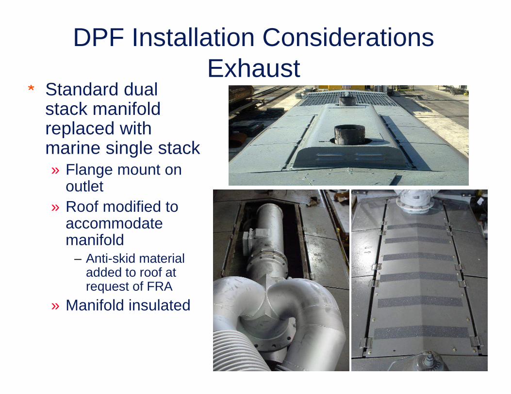
DPF Installation Considerations Exhaust
* Standard dual stack manifold replaced with marine single stack» Flange mount on
outlet» Roof modified to
accommodate manifold
– Anti-skid material added to roof at request of FRA
» Manifold insulated

DPF Installation Considerations Exhaust (cont’d)
* Custom built exhaust pipe connects manifold outlet to DPF inlets» Pipe is also insulated
to retain exhaust heat
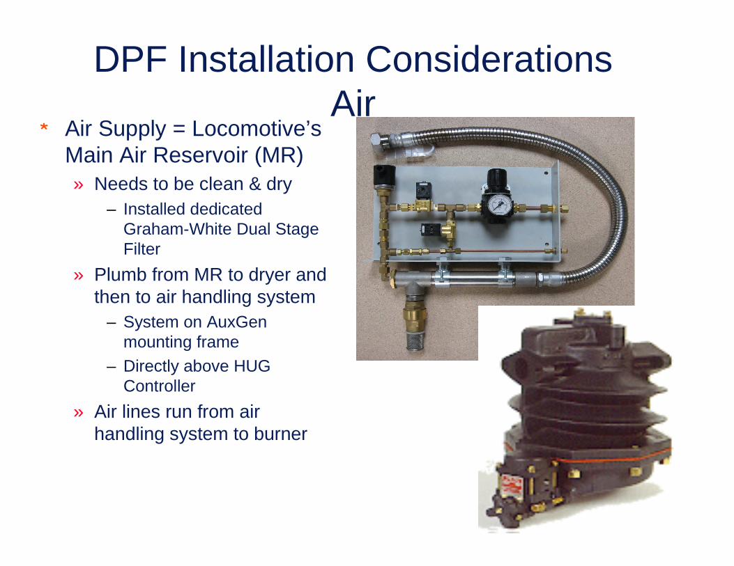
DPF Installation Considerations Air
* Air Supply = Locomotive’s Main Air Reservoir (MR)» Needs to be clean & dry
– Installed dedicated Graham-White Dual Stage Filter
» Plumb from MR to dryer and then to air handling system
– System on AuxGenmounting frame
– Directly above HUG Controller
» Air lines run from air handling system to burner

DPF Installation Considerations Fuel
* Fuel supply for DPF system » Comes directly from
engine return fuel line» System has 24VDC fuel
pumps to supply pressure to burner
» Fuel system valves & pressure regulator mounted above engine’s roots blowers
» Return fuel line to top of locomotive tank

DPF Installation Considerations PLC
* PLC controller» Mounted below air
handling system» Mounted on
AuxGen frame» Supplied with
24VDC power» Connected to all
sensors and control valves

DPF Installation Considerations Locomotive Mods
* Secondary access to top of long hood» Stock access to roof is
blocked by DPF system
» New steps installed on door @ Left Front of long hood
– Door bolted closed
» Cover over radiators replaced with serrated bar grate
– Per FRA request
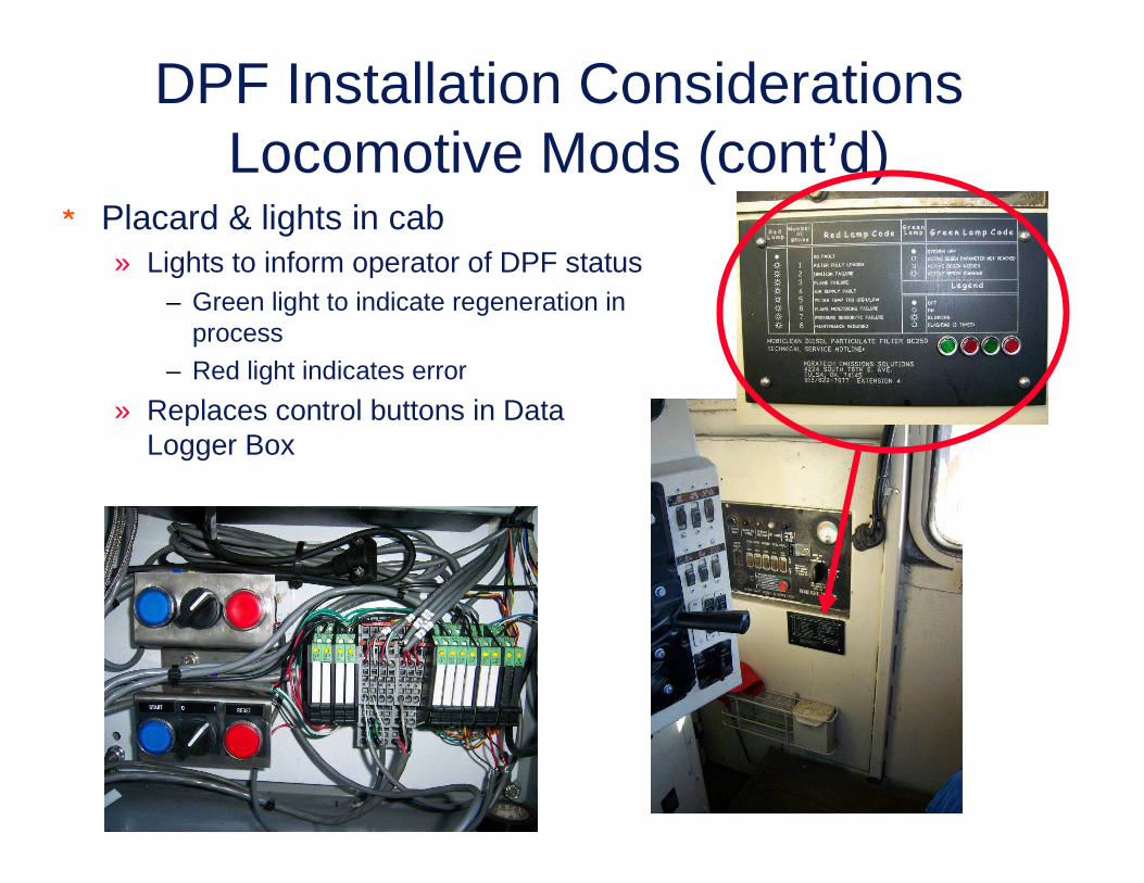
DPF Installation Considerations Locomotive Mods (cont’d)
* Placard & lights in cab» Lights to inform operator of DPF status
– Green light to indicate regeneration in process
– Red light indicates error
» Replaces control buttons in Data Logger Box

DPF Installation Considerations SwRI Data Logger
* Campbell data logger» GPS» Cell phone
– Fixed IP Address
» Monitors– Engine speed– Temperatures
l Exhaustl Burnerl Jacket waterl Ambient
– Pressuresl Barol Exh restriction
– Battery voltage

Application of Experimental DPF System (cont’d)
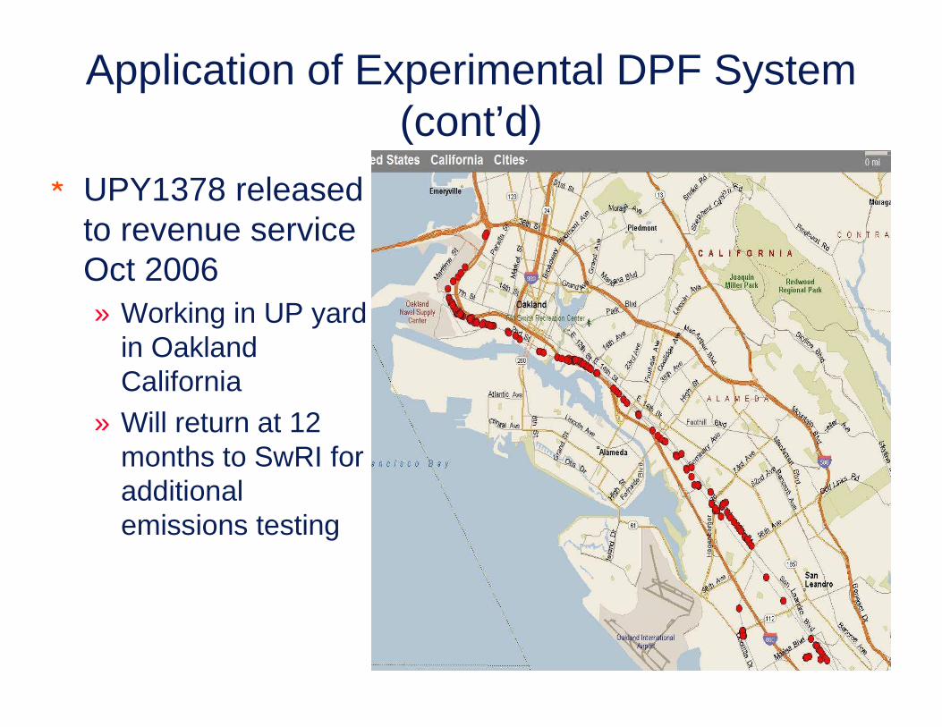
Application of Experimental DPF System (cont’d)
* UPY1378 released to revenue service Oct 2006» Working in UP yard
in Oakland California
» Will return at 12 months to SwRI for additional emissions testing

Application of Experimental DPF System (cont’d)

Application of Experimental DPF System (cont’d)
* BNSF3703 has DPF system installed» Working in yard in San Antonio Texas» Waiting delivery from Hug of next generation DPF
– Test of new DPF– Then release for revenue service

Application of Experimental DPF System (cont’d)
* Wall flow DPF should provide 90(+) % PM reduction
* Current system on UPY1378 & BNSF3708 are only ~ 83% efficient
* Ongoing work to further reduce PM emissions» New DPF material
selections» New ways to pack DPF
brick in housing» Add DOC to the system?
Locomotive Out
W/ DPF
17%
DPF Reduction
83%

Outline* Summary of locomotives fitted with aftertreatment* Application issues/challenges of installing
aftertreatment in US locomotive* European locomotives equipped with DPF * MBTA DOC demo* California Emissions Program (CEP)* US-EPA / UP program to equip and demonstrate
DOC in line-haul locomotive* Application of SCR to EMD Diesel Engines at
Southern California Edison’s Pebbly Beach Generating Station at Santa Catalina Island, California

Application of Experimental DOC* Experimental DOC
installed in EMD SD-60M» Line-haul locomotive» 3,800 traction HP» Turbocharged
* From exterior of locomotive there is no way to tell that DOC system is installed » Novel pre-turbo system» DOC mounted in exhaust
manifolds

Application of DOC (cont’d)
* Manifolds replaced» Experimental DOC
drops into top of manifolds
» Design does not hamper engine maintenance / repair
– IE: PA removal
* Adds manifold surface area » Requires use of
manifold blankets to retain heat
– Energy for turbo
– Keep long hood cooler

Application of DOC (cont’d)

Application of DOC (cont’d)

Application of DOC (cont’d)

Application of Experimental DOC System (cont’d)
* On UP2368 the DOC system reduced PM emissions by 52%» EPA line-haul test cycle» 17 PPM sulfur fuel
Engine Out
W/ DOC
48%DOC
Reduction
52%
DOC M
edia
Reference: Osbone, D. T., et.al, ”Exhaust Emissions from a 2850 kW EMD SD60 Locomotive Equipped with a Diesel Oxidation Catalyst“, ASME Paper JRC-ICE2007-40060, 2007.

Application of Experimental DOC System (cont’d)
* UP2368 released to revenue service Oct 2006» Assigned to
helper/hauler service in LA Basin
» Inspection of DOC at 3 & 6 months
» Final emissions test after 12 months of demonstration

3 Month Inspection of DOCFirst the good news:* No signs of exhaust leaks between manifolds & engine* The insulation blankets were intact & not oil soaked* Catalyst elements showed no signs of cracking* No signs of warping of the manifolds or tracks* Catalyst gaskets were still in place and tight* Found DOC to be relatively clean and free of build-up of PM or ash
» DOC’s were dry (no signs of oil) despite a large amount of time spent at idle* No debris was found in the turbo screen
Now the bad news:* Some of the sections of catalyst substrate broke loose from the top side
of mantel (outer band) due to exhaust pulse» This allowed substrate to move back and forth about a 1/4 inch
– They did not come loose on the bottom– No pieces were lost
» This occurred on approximately 4 of the 16 elements. * Catalyst elements were repaired & re-installed

3 Month Inspection of DOC (cont’d)
6 Month Inspection of DOCSome bad new to report from the 6 month
inspection:* Repair (post three month inspection) did not hold up
» Repair = installing strips of metal welded along the top of the elements to hold the catalyst sections
» These strips failed in a number of places, releasing the substrate» None of the catalyst substrate came completely out of the band
Some good news:* The exhaust manifolds were still in good shape
» No cracks or evidence of leaks* No oil or contamination buildup on catalyst face
* New designed DOC CAT’s are ready to install and continue demonstration

6 Month Inspection of DOC (cont’d)

“The Curse of the Test Locomotive”* Original test locomotive was UP2448
Bad things can happen with a sample size of one

Outline* Summary of locomotives fitted with aftertreatment* Application issues/challenges of installing
aftertreatment in US locomotive* European locomotives equipped with DPF * MBTA DOC demo* California Emissions Program (CEP)* US-EPA / UP program to equip and demonstrate
DOC in line-haul locomotive* Application of SCR to EMD Diesel Engines at
Southern California Edison’s Pebbly Beach Generating Station at Santa Catalina Island, California

Application of SCR to EMD Diesel Engines at
Southern California Edison’s
Pebbly Beach Generating StationSanta Catalina Island, California
By
John Hedrick210-522-2336
Steve Fritz210-522-3645
Nov. 2004
Southwest Research Institute - San Antonio, TX

Background* TxDOT considering SCR for NOx reduction
from Galveston Ferry Operations» Fleet of 5 vessels each running EMD 12-645-E
engines
* Question from SwRI to EMD:» Are you aware of any SCR applications on EMD
engines?» Answer: Yes, there is one. SoCal Edison using a
NOxTECH system on an EMD power generating engines on Santa Catalina Island off of the coast of Los Angeles.
* Lets find out more……

Electrical Power on Catalina
* SoCal Edison provides all electrical power on Catalina Island
* Base load of plant was ~ 5 MW at the time of visit
* Typical “high” load for plant is ~ 6 MW* Maximum output of the power plant is
9.4 MW

* Power generated by six EMD diesel fueled engines» 2 Roots blown engines
– 16-645l Two unitsl Both operate at 900 RPM
» 4 Turbocharged engines– 16-567 Operating at 720 RPM– 12-645– 16-645– 16-710
* No two engines are the same age» Engines added as power demands increased
EMD Diesel Power Generation

Exhaust Emission Restrictions* Catalina Island regulated by South Coast Air Quality Management District
(SCAQMD)* An EPA Title V facility
» Title V permit issued by State and local authorities– SCAQMD in this case
» Title V often called “part 70 permits”– Regulations that establish minimum standards for State permit programs are found
in 40 CFR part 70.”
» Additional details can be found at: http://www.epa.gov/air/oaqps/permits/
* To meet emissions permit emissions levels, exhaust aftertreatment was required» 70% NOx reduction (typically from 1000 ppm to 300 ppm) for all engines
except 710
» 710 engine required 90% NOx reduction – from 650 ppm to < 51 ppm)
* Currently operating under a PM variance due to application of SCR for aggressive NOx control
Diesel Fuel* DF-2 used meets CARB Ultra Low Sulfur Diesel Fuel
(ULSDF) requirements» Used since June 2004
» Cost premium for ULSDF is ~10%
» Level of Sulfur in fuel is not constant– Thought to be due to contamination during transport
* No know engine related issues by using ULSDF» The facility has fuel flow measurement devices on each of the
engines that had to be recalibrated after switching to ULSDF– Due to higher API gravity of the ULSDF

SCR Emissions Reduction System* 1995 – Installed NOxTECH NOx reduction system on one 2.8 MW
engine
» Uses gas-phase reactions to reduce NOx in the temperature range of 1400 to 1550°F with supplemental burner
» Used no catalytic surfaces
» Reported 90% NOx reduction
» Considered Best Available Control Technology (BACT) by SCAQMD
* 2003-04 Replaced NOxTECH with Johnson Matthey SCR
» Installed SCR on all 6 engines
» Plant uses Urea as a reagent
» Provides very low NOx levels
* JM Oxidation catalyst used post SCR
» Reduces ammonia “slip”
» Oxidation cat can also reduce volatile organic fraction in PM emissions
» Also reduces Carbon Monoxide

Exhaust System Layout
Oxidation Cat(Inside SCR housing)
Engine Room
Emissions Sample Probe
Exhaust Stack
SCR catalyst
Urea Injector
Engine Muffler
Note that the entire exhaust system is insulated.

Urea Storage* Urea is delivered to the
island in bulk » Delivered as a liquid
» No significant freezing issues at this facility
* Two 5000 gallon bulk urea tanks in fuel storage area
* Smaller urea tanks at each engine» JM Control / metering system
next to urea tank

Urea Consumption* Urea consumption rates
» 23 gallons per hour for 710 engine
– This is approximately 12 to 15% of fuel consumed for a 4,000 hp engine
– 9 to 14 gallons per hour for other engines
* Urea costs ~ 1.50 $/gallon
» Cost has been increasing at a similar rate to diesel fuel
* Amount of urea injected based on a map in SCR control
system
* SoCal Edison reports that current Urea consumption is
about 10 to 15% higher than expected

Urea Injector
* Urea injected ≈ 15-
feet upstream of the
SCR catalyst
* Johnson Matthey
urea injector
» Air-assisted injector
used to improve
mixing
15-feet of mixing

Continuous Emissions Monitoring
* Emissions from the engine exhaust stack are continuously monitored to assure that power plant emissions are under permitting limits
Emissions sample probe
in each exhaust stack

SCR Package* The SCR package for the
16-710 engine is relatively large» Roughly 8’ X 8’ X 8’» = 512 ft3 = 78x swept engine
volume!
* The exhaust pipe ~ 24”diameter» Plus insulation on outside of
pipe
* The oxidation catalysts are mounted as the last row of catalysts elements in the SCR housing» Not in a separate housing

SCR Layout* SCR housing contains
removable catalyst elements that form 5 rows
* First row of elements were originally uncatalyzed when using 200 Cell Per Inch (CPI) elements » First row used to protect more
expensive catalyzed elements» First row was replaced with
catalyzed elements when SCR was converted to 100 CPI elements
* Last row of elements are the oxidation catalyst
Flow Direction
2’
2’
2’ 2’ 2’
8’
8’

Problem: SCR Catalyst Plugging* Differential pressure across the
SCR system is a major issue and monitored closely, as it affects the backpressure on the engine
* Pressure increases over time» PM starts to block flow through the
SCR catalyst » PM is primarily on face of catalyst
– surface loading» Need to clean catalyst elements to
remove PM
* Issue greatly reduced by converting from 200 CPI to 100 CPI catalyst elements
Plugged section of catalyst
Pressure Differential measurement

SCR Catalyst Plugging

EMD Backpressure Limits* Maximum engine exhaust back pressure
is set at a very low limit by EMD» 5 to 8 inches of water column on the
turbocharged engines» 15 inches of water column on the roots
blown engines– The roots blown engines typically plug the
SCR faster due to higher PM rates
* Higher back pressure can effect crankcase (CC) pressure
» Engine safety trips at -0.8 inch water column CC pressure
» Elevated exhaust back pressure on turbocharged engines hits this limit very quickly
» Roots blown engines with closed CC not effected

SCR Catalyst Cleaning* Cleaning of PM from SCR
element (to reduce back pressure) requires:
» SCR be cool enough to allow staff to handle elements
» Staff must be certified to handle hazardous materials
– elements coated with vanadium– PM can contain heavy metals
and other contaminates » Cleaning for So Cal is
performed by a contractor» All material removed from the
face of SCR must be disposed of properly
* Cleaning 710 SCR underway during SwRI visit
» Dirty pressure drop across catalyst was 1.6 in. H2O
» Cleaning reduced this to 0.8 in. H2O
» At 1.6 in. H2O, maybe cleaned a little earlier than necessary

Methods to Reduce PM Plugging of SCR Catalysts
* Reducing engine-out PM should increase time between cleanings» SoCal already advanced fuel injection timing to TDC
– Injection retard had been used to reduce NOX but increased PM– Let SCR remove the NOX , reduce the PM level, and improve fuel
economy
» SwRI offered additional suggestions:– The use of low oil consumption rings and liners
l EMD locomotive Tier II ring and liner kits for low oil consumption?
– Switch to multi-viscosity lubricating oil to reduce oil consumptionl use of SAE 20W-40 in place of SAE 40
– Switch from 17 TBN oil to 13 TBN, or even lowerl High TBN oils may not be needed when using low sulfur diesel fuell High TBN oils may have higher ash concentrations which means more
ash presented to the SCR catalyst – likely contributor to plugging.
– Purge crankcase ventilation post SCR to reduce oil and PM load going into SCR
– Future use of a PM filter before the SCR
Initial Engine Start & Warm-Up Issues
* Catalyst warm up a slow process at power plant » Engine and catalyst warmed up for up to one hour
before Urea is turned on– Target temps in the catalyst is 550°to 560°F before urea
is injected to exhaust stream– Initial start white smoke– Transitions to black smoke as load is applied, and before
turbo and exhaust up to operating temperature– Then Orange/Red/Yellow haze, likely due to NO2
formation at the oxidation catalyst, until Urea injection starts.
» SoCal receives public complaints about smoke during this warm-up period.

Summary* SCR has been successfully applied to EMD
turbocharged and roots-blown engines in power generation applications» SoCal overall happy with performance» Operating well within SCAQMD permit levels» Essentially 1-year of revenue service experience
* Catalyst plugging and cleaning frequency improving» 200 CPI to 100 CPI SCR catalyst made a big improvement» Advanced fuel injection timing back to TDC
* SoCal Edison and JM team very open with information» Especially after they realized we were not trying to sell
them anything!

Observations for Rail and Marine
* JM SCR system is very large, at 78 X swept volume» Obvious packing issues on locomotives and
vessels
* EMD exhaust back pressure limits drive the need for large SCR package.» Need to assess/understand/engineer solution to
enable EMD turbocharged engines to tolerate significantly higher backpressure.
* High engine-out NOx levels mean high Urea consumption rates, and at $1.50/gallon for Urea, this trade-off needs to be considered.

Acknowledgements / ContactsSpecial thanks for the cooperation of:
Gary Huffman
Operations ManagerSouthern California Edison - Pebbly Beach Generating Station
(310) 510-4315
And
Dave Montgomery and Bill Licausi
Southern California Edison - Pebbly Beach Generating Station
Rich RosowskiSCR Sales Manager
Johnson Matthey
(610) [email protected]