Embed Size (px)
Citation preview

VERE
VERE: Virtual Embodiment and Robotic Re-Embodiment
Integrated Project no. 257695
FP7-ICT-2009-5
WorkPackage WP3: Intention Recognition
Deliverable D3.2
First BBCI Prototype
Christoph Hintermüller, GTEC
Release date: 14 Jan. 2012
Status: Confidential

VERE – FP7-257695 D3.2 First BBCI Prototype
Documentation Deliverable 3.2 ii 14/01/2012
EXECUTIVE SUMMARY
This document describes the brain and body computer interface developed in
workpackage WP3. It lists the different parts of the first prototype and provides the
description of the EEG based steady state visual evoked potential (SSVEP) and P300
brain computer interface paradigms used to recognize the high-level intentions of the
user. For the detection of erroneous selections of actions either by the user or the BBCI
system the Error Potential generated by the human brain in these cases will be
exploited. First steps of identifying such error-related potentials from EEG signals are
reported.
While high-level intentions decide on the what should be executed (transformed into a
sequence of actions by WP4), low-level intentions aim at modifying how these actions
are executed (quality of actions) by taking into account the actual user mental state.
First steps into recognizing low-level intentions from EEG and physiological signals
have been undertaken by recording an emotional database.

VERE – FP7-257695 D3.2 First BBCI Prototype
Documentation Deliverable 3.2 iii 14/01/2012
Deliverable Identification Sheet
IST Project No. FP7-ICT-2009-5 – Project 257695
Acronym VERE
Full title VERE: Virtual Embodiment and Robotic Re-Embodiment
Project URL http://www.vereproject.eu/
EU Project Officer Jean-Marie AUGER
Deliverable
Work package WP3 Intention Recognition
Date of delivery Contractual M 18 Actual 13. January 2012
Status version. 1 final
Nature Prototype Report Dissemination
Dissemination Level
Public Consortium
Authors (Partner) C. Hintermüller (GTEC), K. Blom (UB), M. Slater (UB), Robert Jenke (TUM), Mohammad Abu-Alqumsan (TUM), Nikolas Martens (TUM), Angelika Peer (TUM), Pierre (CNRS), Abder Kheddar (CNRS)
Responsible Author
C. Hintermüller Email [email protected]
Partner GTEC Phone +43 7251 22240 17
Abstract (for dissemination)
The first BBCI prototype was successfully developed and installed at several VERE partner institutions. First studies are already successfully running.
Keywords BCI, physiological monitoring system, P300, SSVEP, error potentials
Version Log
Issue Date
30.11.2011
Rev No.
001
Author
C. Hintermüller
Change
First Draft
13.01.2012 002 C. Hintermüller Revised according to comments of reviewers

VERE – FP7-257695 D3.2 First BBCI Prototype
Documentation Deliverable 3.2 iv 14/01/2012
TABLE OF CONTENTS
EXECUTIVE SUMMARY ..................................................................................................... II
TABLE OF CONTENTS ...................................................................................................... IV
1 INTRODUCTION .............................................................................................................. 1
2 BLOCK DIAGRAM .................................................................................................... 1
3 HIGH LEVEL INTENTION PROCESSING AND DETERMINATION .................................... 3
3.1 P300 Paradigm ........................................................................................................ 3
3.2 SSVEP Paradigm .................................................................................................... 4
3.3 Error-related Potentials ........................................................................................... 4
3.4 System Layout ........................................................................................................ 5
3.5 Remote Stimulus Display ....................................................................................... 7
3.6 Electrodes and electrode cap .................................................................................. 8
3.7 Biosignal amplifier: g.USBamp ............................................................................. 9
4 RECOGNITION OF LOW-LEVEL INTENTIONS .............................................................. 10
4.1 Physiological Monitoring ..................................................................................... 10
5 BCI SYSTEM INSTALLATIONS ..................................................................................... 11
6 REFERENCES ............................................................................................................... 12

VERE-FP7-257695 D3.2 First BBCI Prototype
14/01/2012
1
1 INTRODUCTION
The goal of workpackage 3 is to develop a system for identifying the intentions of the
user and to extract their different components and aspects. There exist different levels of
intentions. High level intentions include all goal oriented intentional actions and plans
such as grabbing a glass or walking to the cinema, whereas low level intentions
represent all actions and behavior which is not directed towards a specific goal. They
typically define how a high level intention, a goal oriented action, is performed, the
level of commitment to it, by considering e.g. different emotional states. The Body
Brain and Body Computer Interface System (BBCI) records biosignals like the EEG,
ECG, the respiration or the galvanic skin response of the user’s body. It extracts the
physiological parameters and features thereof and uses them to generate measures
which represent both types of user’s intentions.
The first prototype of the BBCI uses the EEG signal for selecting discrete commands
which are passed to the robotic and virtual avatar controller system. The remaining
biosignals such as ECG, galvanic skin response, etc. and related physiological
parameters like heart rate or respiration rate are recorded and mapped to different
qualities of robot actions in WP4.
In the following section 2 the components of the first BBCI prototype and the interfaces
between them are shown. The block diagram helps to clarify the description and to
visualize all required interactions between the BBCI components.
2 BLOCK DIAGRAM
A block diagram of the main hardware devices and software components of the BBCI
system is shown in Figure 1. The dashed lines represent the interfaces between them
and the arrows indicate the direction along with the data and information are passed
onwards to the next component. The arrow labels indicate the data to be exchanged
between the different components. The interfaces I2, I3, I5, I6, I7, I8 and I9 interconnect the BBCI prototype system with the components of the VERE prototype
developed within other workpackages. These interfaces have been defined and
described in detail in deliverable D3.1.
Basically, two types of intentions are recognized by the BBCI system, i.e. high-level
and low-level intentions. The high-level commands recognized via the active BCI
paradigm (e.g P300 or SSVEP) are passed on to the next system blocks for the
embodiment of the intentions on the robot (WP4,5) or the the virutual avatar (WP4,6).
Herein, it is decided how these commands are interpreted and it is decided how they are
executed on the virtual or robotic avatar in succeeding work packages. The low-level
intentions are processed in parallel to the high-level intentions. While high-level
intentions are mapped in WP4 into a sequence of robot actions, the low-level intentions
determine the quality of how these single actions are implemented.
VERE-FP7-257695 D3.2 First BBCI Prototype
14/01/2012
2
I2 Active EEG electrodes and biosignal amplifier including g.USBamp driver and
MATLAB/Simulink API
I3 Biosignal sensors for ECG, respiration, galvanic skin response, SpO2, pulse and biosignal
amplifier including g.USBamp driver API
I5A/B/C XML interface between multimodal intention recognition system and avatar, either virtual or
robotic
I6 Body motion recording interface
I7 Facial motion recording interface
I8A BCI control interface of the head mounted displays
I8B HMD trigger interface using digital IO or direct network connection to the BCI processing
system
I9 binocular image display interface of the head mounted displays
I1 is the interface to the fMRI system which is not included in the first prototype. I4 is the knowledge base which
will be integrated into the Low-Level Intentions in the next prototype.
Figure 1: Block diagram of the first BBCI prototype including the connections and
interfaces to components developed within the workpackages 2, 4, 5 and 6.
VERE-FP7-257695 D3.2 First BBCI Prototype
14/01/2012
3
3 HIGH LEVEL INTENTION PROCESSING AND DETERMINATION
Different BCI paradigms will be used to record the high-level intentions of the user. The
BBCI prototype implements the stimulus based P300 (section 3.1) and SSVEP
(section 3.2) paradigms. Both paradigms are able to recognize a target stimulus e.g. a
single character or icon, to which a user is attending out of many other non target
stimuli. The interface translates mental response of the users to the target stimulus to
predefined xml strings which closely correlate to the high-level intentions the user most
likely has within a specific situation.
Currently Error-related Potentials (ErrPs) are being explored in parallel to recognize
user’s cognitive error states. For instance, the interaction ErrPs indicate user awareness
of errors done by the interface or that he had selected the wrongly selected target
symbols. We try to simulate this case by erroneous keyboard interactions, where users
try to push a ball into a hole (both laying on the same horizontal line on the screen)
using keyboard left and right arrows. User input is translated by the interface into the
wrong direction with a probability of error, P. The current implementation of the ErrP
detection paradigm is described in detail in section 3.3. It is planned to extend the
recognition of ErrPs to BCI paradigms, like P300 and SSVEP, to obtain an
instantaneous verification and validation of the identified intention. Ignoring user
interactions, which are followed by ErrPs, leads to higher information transfer
rates [3-5].
3.1 P300 Paradigm
Whenever an unlikely event which is awaited by the user occurs randomly between
other events a so called P300 evoked potential is elicited. It manifests itself in a positive
deflection in the amplitude of the EEG signal around 300 ms after a visual stimulus
onset.
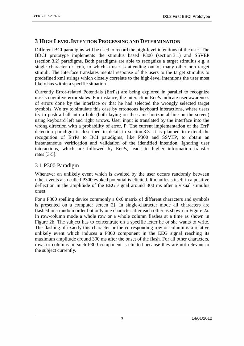
For a P300 spelling device commonly a 6x6 matrix of different characters and symbols
is presented on a computer screen [2]. In single-character mode all characters are
flashed in a random order but only one character after each other as shown in Figure 2a.
In row-column mode a whole row or a whole column flashes at a time as shown in
Figure 2b. The subject has to concentrate on a specific letter he or she wants to write.
The flashing of exactly this character or the corresponding row or column is a relative
unlikely event which induces a P300 component in the EEG signal reaching its
maximum amplitude around 300 ms after the onset of the flash. For all other characters,
rows or columns no such P300 component is elicited because they are not relevant to
the subject currently.
VERE-FP7-257695 D3.2 First BBCI Prototype
14/01/2012
4
To measure the P300 component acquisition of EEG signals from 8 electrode positions
mostly over occipital and parietal regions is sufficient [1]. To train the BCI system an
arbitrary word like LUCAS is announced to the system to be aware of which characters
the subject is supposed to concentrate on (targets) and which not (non-targets). Each of
these letters respectively each row and column flashes several times e.g. for 100 ms per
flash. The subject focuses on each of these letters, one after the other and increments a
mentally running count whenever the letter flashes the subject is currently concentrating
on. EEG data of a specific time interval around each flash is then sent to a LDA
classifier to learn to distinguish the typical EEG signal form of the target characters
from the typical signal form of all other non-targets.
The EEG data were recorded with a biosignal amplification unit (g.tec medical
engineering GmbH, Austria) at 256 Hz sample rate and transferred to the computer. A
notch filter (50 Hz or 60 Hz) and a band pass filter were applied to the signals in order
to eliminate possible artifacts before they were down-sampled to 64 Hz. Data from 100
ms before each flash onset to 700 ms afterwards were filtered and down-sampled again
to get 12 feature values (i.e. samples) per channel and flash. These data chunks were
sent to the LDA to determine if a target character flashed or not. A MATLAB/Simulink
model controls the interface masks, processes the received data via a specific device
driver and dispatches the targeted commands via the described UDP XML message
passing interface. The subjects were sitting in front of a computer screen and were
instructed to relax as much as possible.
3.2 SSVEP Paradigm
The steady state visually evoked potential (SSVEP) is elicited, if a subject is exposed to
a visual stimulus which is repeated with a frequency of at least 6 Hz. For example, a
flickering LED can be used as stimulating device. If the LED flickers with a frequency
of 14 Hz, the response of a subject paying attention to the LED is increased to 14 Hz. A
spectral analysis of the captured EEG data shows a clear peak at 14 Hz. If several LEDs
flicker at different frequencies and the user pays selective attention to one of the LEDs,
the captured SSVEP can be used as input method for a BCI.
3.3 Error-related Potentials
Interaction Error-related potentials (ErrPs) are special features that can be detected in
the EEG, after a wrong action selection by the BCI system or the user. After the onset of
the feedback indicating the selected action, these features can be distinguished by first, a
(a) (b)
Figure 2: Screen layout of a 36 character speller. Either a single character is
highlighted (a) at a certain time or a whole row or column (b).
VERE-FP7-257695 D3.2 First BBCI Prototype
14/01/2012
5
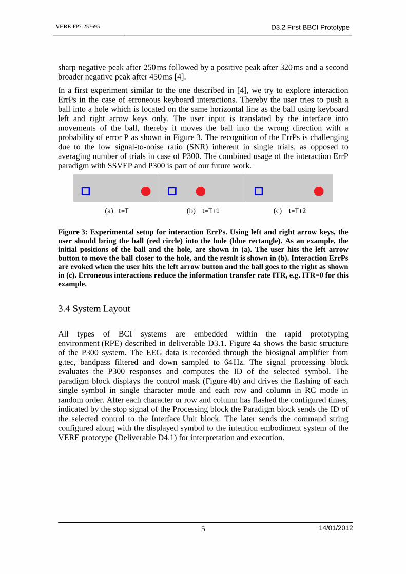
sharp negative peak after 250 ms followed by a positive peak after 320 ms and a second
broader negative peak after 450 ms [4].
In a first experiment similar to the one described in [4], we try to explore interaction
ErrPs in the case of erroneous keyboard interactions. Thereby the user tries to push a
ball into a hole which is located on the same horizontal line as the ball using keyboard
left and right arrow keys only. The user input is translated by the interface into
movements of the ball, thereby it moves the ball into the wrong direction with a
probability of error P as shown in Figure 3. The recognition of the ErrPs is challenging
due to the low signal-to-noise ratio (SNR) inherent in single trials, as opposed to
averaging number of trials in case of P300. The combined usage of the interaction ErrP
paradigm with SSVEP and P300 is part of our future work.
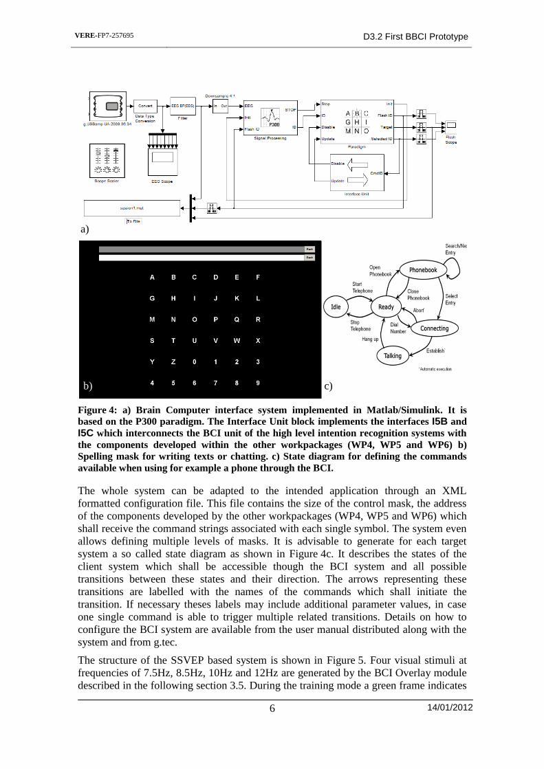
3.4 System Layout
All types of BCI systems are embedded within the rapid prototyping
environment (RPE) described in deliverable D3.1. Figure 4a shows the basic structure
of the P300 system. The EEG data is recorded through the biosignal amplifier from
g.tec, bandpass filtered and down sampled to 64 Hz. The signal processing block
evaluates the P300 responses and computes the ID of the selected symbol. The
paradigm block displays the control mask (Figure 4b) and drives the flashing of each
single symbol in single character mode and each row and column in RC mode in
random order. After each character or row and column has flashed the configured times,
indicated by the stop signal of the Processing block the Paradigm block sends the ID of
the selected control to the Interface Unit block. The later sends the command string
configured along with the displayed symbol to the intention embodiment system of the
VERE prototype (Deliverable D4.1) for interpretation and execution.
(a) t=T
(b) t=T+1
(c) t=T+2
Figure 3: Experimental setup for interaction ErrPs. Using left and right arrow keys, the
user should bring the ball (red circle) into the hole (blue rectangle). As an example, the
initial positions of the ball and the hole, are shown in (a). The user hits the left arrow
button to move the ball closer to the hole, and the result is shown in (b). Interaction ErrPs
are evoked when the user hits the left arrow button and the ball goes to the right as shown
in (c). Erroneous interactions reduce the information transfer rate ITR, e.g. ITR=0 for this
example.
VERE-FP7-257695 D3.2 First BBCI Prototype
14/01/2012
6
The whole system can be adapted to the intended application through an XML
formatted configuration file. This file contains the size of the control mask, the address
of the components developed by the other workpackages (WP4, WP5 and WP6) which
shall receive the command strings associated with each single symbol. The system even
allows defining multiple levels of masks. It is advisable to generate for each target
system a so called state diagram as shown in Figure 4c. It describes the states of the
client system which shall be accessible though the BCI system and all possible
transitions between these states and their direction. The arrows representing these
transitions are labelled with the names of the commands which shall initiate the
transition. If necessary theses labels may include additional parameter values, in case
one single command is able to trigger multiple related transitions. Details on how to
configure the BCI system are available from the user manual distributed along with the
system and from g.tec.
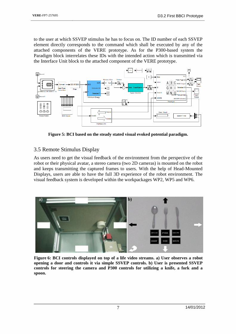
The structure of the SSVEP based system is shown in Figure 5. Four visual stimuli at
frequencies of 7.5Hz, 8.5Hz, 10Hz and 12Hz are generated by the BCI Overlay module
described in the following section 3.5. During the training mode a green frame indicates
a)
b) c)
Figure 4: a) Brain Computer interface system implemented in Matlab/Simulink. It is
based on the P300 paradigm. The Interface Unit block implements the interfaces I5B and
I5C which interconnects the BCI unit of the high level intention recognition systems with
the components developed within the other workpackages (WP4, WP5 and WP6) b)
Spelling mask for writing texts or chatting. c) State diagram for defining the commands
available when using for example a phone through the BCI.
VERE-FP7-257695 D3.2 First BBCI Prototype
14/01/2012
7
to the user at which SSVEP stimulus he has to focus on. The ID number of each SSVEP
element directly corresponds to the command which shall be executed by any of the
attached components of the VERE prototype. As for the P300-based system the
Paradigm block interrelates these IDs with the intended action which is transmitted via
the Interface Unit block to the attached component of the VERE prototype.
3.5 Remote Stimulus Display
As users need to get the visual feedback of the environment from the perspective of the
robot or their physical avatar, a stereo camera (two 2D cameras) is mounted on the robot
and keeps transmitting the captured frames to users. With the help of Head-Mounted
Displays, users are able to have the full 3D experience of the robot environment. The
visual feedback system is developed within the workpackages WP2, WP5 and WP6.
Figure 5: BCI based on the steady stated visual evoked potential paradigm.
a) b)
Figure 6: BCI controls displayed on top of a life video streams. a) User observes a robot
opening a door and controls it via simple SSVEP controls. b) User is presented SSVEP
controls for steering the camera and P300 controls for utilizing a knife, a fork and a
spoon.
VERE-FP7-257695 D3.2 First BBCI Prototype
14/01/2012
8
Through the interface I8 it is possible to merge the stimuli required by the BBCI system
with the video stream from the cameras of the robot or the virtual scenery created by the
modules developed in WP5 and WP6. The combination of video stream and BCI
controls enables the user to observe the environment, the set of possible actions and the
effects of their executed actions.
a) b)
Figure 6 shows examples of what users might see when wearing the HMD. In Figure 6a
the SSVEP paradigm is overlaid on the video stream received from a robot while
opening a door. The example in Figure 6b shows the combined display of SSVEP and
P300 controls. In both examples the display for only one eye (left or right) is shown.
The BCI controls are generated by the BCIOverlay module DLL which the visual
feedback system loads and initializes when needed during runtime. This DLL uses
native openGL commands to draws the P300 and SSVEP stimuli and the different
symbols and characters representing the different actions the user may execute through
the attached avatar.
The module is controlled by and connected to the BCI paradigm block (Figure 4a and
Figure 5a) through a bidirectional network socket connection using the UDP network
protocol. Whenever a set of stimuli P300 or SSVEP are presented to the user the
module indicates this by sending a trigger message indicating the highlighted controls to
the BCI Paradigm block over the UPD socket. These trigger signals are then converted
and distributed to the Simulink blocks for the P300 and SSVEP processing.
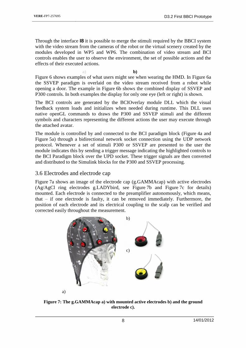
3.6 Electrodes and electrode cap
Figure 7a shows an image of the electrode cap (g.GAMMAcap) with active electrodes
(Ag/AgCl ring electrodes g.LADYbird, see Figure 7b and Figure 7c for details)
mounted. Each electrode is connected to the preamplifier autonomously, which means,
that – if one electrode is faulty, it can be removed immediately. Furthermore, the
position of each electrode and its electrical coupling to the scalp can be verified and
corrected easily throughout the measurement.
a)
b)
c)
Figure 7: The g.GAMMAcap a) with mounted active electrodes b) and the ground
electrode c).
VERE-FP7-257695 D3.2 First BBCI Prototype
14/01/2012
9
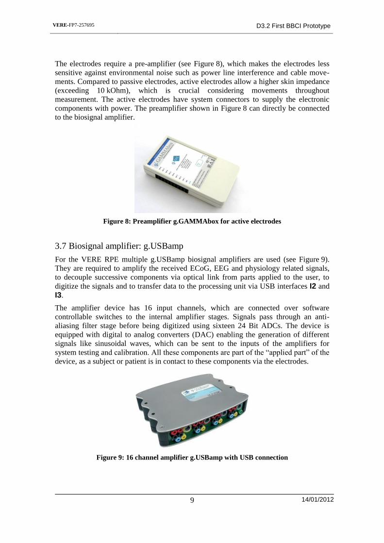
The electrodes require a pre-amplifier (see Figure 8), which makes the electrodes less
sensitive against environmental noise such as power line interference and cable move-
ments. Compared to passive electrodes, active electrodes allow a higher skin impedance
(exceeding 10 kOhm), which is crucial considering movements throughout
measurement. The active electrodes have system connectors to supply the electronic
components with power. The preamplifier shown in Figure 8 can directly be connected
to the biosignal amplifier.
3.7 Biosignal amplifier: g.USBamp
For the VERE RPE multiple g.USBamp biosignal amplifiers are used (see Figure 9).
They are required to amplify the received ECoG, EEG and physiology related signals,
to decouple successive components via optical link from parts applied to the user, to
digitize the signals and to transfer data to the processing unit via USB interfaces I2 and
I3.
The amplifier device has 16 input channels, which are connected over software
controllable switches to the internal amplifier stages. Signals pass through an anti-
aliasing filter stage before being digitized using sixteen 24 Bit ADCs. The device is
equipped with digital to analog converters (DAC) enabling the generation of different
signals like sinusoidal waves, which can be sent to the inputs of the amplifiers for
system testing and calibration. All these components are part of the “applied part” of the
device, as a subject or patient is in contact to these components via the electrodes.
Figure 8: Preamplifier g.GAMMAbox for active electrodes
Figure 9: 16 channel amplifier g.USBamp with USB connection
VERE-FP7-257695 D3.2 First BBCI Prototype
14/01/2012
10
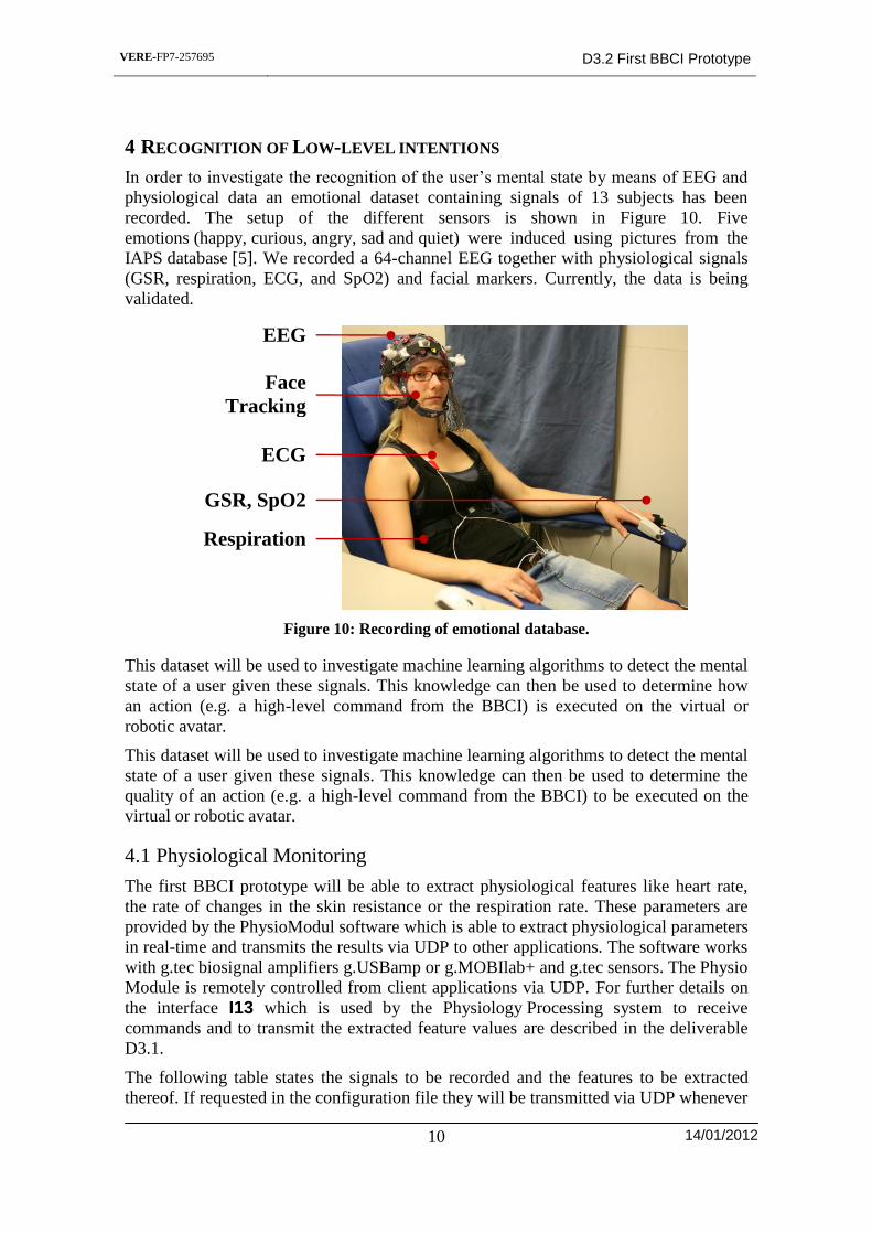
4 RECOGNITION OF LOW-LEVEL INTENTIONS
In order to investigate the recognition of the user’s mental state by means of EEG and
physiological data an emotional dataset containing signals of 13 subjects has been
recorded. The setup of the different sensors is shown in Figure 10. Five
emotions (happy, curious, angry, sad and quiet) were induced using pictures from the
IAPS database [5]. We recorded a 64-channel EEG together with physiological signals
(GSR, respiration, ECG, and SpO2) and facial markers. Currently, the data is being
validated.
This dataset will be used to investigate machine learning algorithms to detect the mental
state of a user given these signals. This knowledge can then be used to determine how
an action (e.g. a high-level command from the BBCI) is executed on the virtual or
robotic avatar.
This dataset will be used to investigate machine learning algorithms to detect the mental
state of a user given these signals. This knowledge can then be used to determine the
quality of an action (e.g. a high-level command from the BBCI) to be executed on the
virtual or robotic avatar.
4.1 Physiological Monitoring
The first BBCI prototype will be able to extract physiological features like heart rate,
the rate of changes in the skin resistance or the respiration rate. These parameters are
provided by the PhysioModul software which is able to extract physiological parameters
in real-time and transmits the results via UDP to other applications. The software works
with g.tec biosignal amplifiers g.USBamp or g.MOBIlab+ and g.tec sensors. The Physio
Module is remotely controlled from client applications via UDP. For further details on
the interface I13 which is used by the Physiology Processing system to receive
commands and to transmit the extracted feature values are described in the deliverable
D3.1.
The following table states the signals to be recorded and the features to be extracted
thereof. If requested in the configuration file they will be transmitted via UDP whenever
Figure 10: Recording of emotional database.
EEG
Face
Tracking
ECG
Respiration
GSR, SpO2

VERE-FP7-257695 D3.2 First BBCI Prototype
14/01/2012
11
an updated value of the feature is available. If an update is available for several features
at the same time one UDP message containing all changes will be transmitted.
ECG:
o Heart-rate (HR): mean heart rate in beats per minute computed for the past N
seconds.
o Heart-rate variability (HRV): Heart-rate variability over the past N seconds
o Ratio of normalized HR and normalized HRV: Both HR and RMSSD will be
normalized to their maximum signal range observed during the reference
segment at the beginning of the session.
o RMSSD: Root Mean Square of duration variations of adjacent RR intervals for
the past N seconds
o HR/RMSSD: Ratio between normalized HR and normalized RMSSD. Both HR
und RMSSD will be normalized to their maximum signal range observed during
the reference segment at the beginning of the session.
o pNN50: Percentage of adjacent RR intervals differing by more than 50 ms
within the past N seconds.
o HR/pNN50: Ratio between normalized HR and normalized pNN50. Both values
HR and pNN50 are normalized to their maximum signal range observed during
the reference segment at the beginning of the session.
GSR:
o ERD: Normalized relative Means (in percent) for the past N seconds.
TaskActive: Indicates if a task is currently active and running, or not.
Respiration:
o Respiration Rate
o Duration of inspiration and expiration intervals
o Depth of inspiration and expiration
o Pauses during inspiration and expiration.
EEG: The feature signals required for the recognition of low level intentions are still
under investigation and thus not yet defined
5 BCI SYSTEM INSTALLATIONS
Currently the following partners have running BCI systems
IDC – 16 channel BCI system
EPFL – 48 channel BCI system
UCL – 16 channel BCI system
FSL – 16 channel BCI system
TUM – 32 channel BCI system
CNRS – 16 channel BCI system
g.tec – 16 channel BCI system

VERE-FP7-257695 D3.2 First BBCI Prototype
14/01/2012
12
UB – 8 channel BCI system
IDIBAPS – 16 channel BCI system
PERCO – 16 channel BCI system
6 REFERENCES
1. E. W. Sellers, D. J. Krusienski, D. J. McFarland, T. M. Vaughan, and J. R. Wolpaw, “A P300 event-
related potential brain-computer interface (BCI): The effects of matrix size and inter stimulus interval
on performance,” Biological Psychology, vol. 73, no. 3, pp. 242-252, October 2006.
2. E. Donchin, K. M. Spencer, and R. Wijesinghe, “The mental prosthesis: assessing the speed of a P300-
based brain-computer interface,” IEEE Trans. Rehabil. Eng., vol. 8, no. 2, pp. 174-179, June 2000.
3. P. W. Ferrez and J. d. R. Millán, “You are wrong! - Automatic detection of interaction errors from
brain waves,” In Proceedings of the 19th International Joint Conference on Artificial Intelligence,
Edinburgh, UK, August 2005.
4. P. W. Ferrez and J. d. R. Millán, ”Error-related EEG potentials generated during simulated brain-
computer interaction,” In IEEE Trans. Biomed. Eng. 55, 923–929, 2008.
5. Schalk, G., Wolpaw, J. R., McFarland, D. J., and Pfurtscheller, G., “EEG-based communication:
presence of an error potential”. Clinical neurophysiology : official journal of the International
Federation of Clinical Neurophysiology, 111(12), 2138-44, 2000.
6. Lang, P.J., Bradley, M.M., & Cuthbert, B.N. (2008). International affective picture system (IAPS):
Affective ratings of pictures and instruction manual. Technical Report A-8. University of Florida,
Gainesville, FL.