Embed Size (px)
Citation preview
Page 1 of 16
TECHNICAL APPROVALS FOR CONSTRUCTION
APPROVAL
INSPECTION
TESTING
CERTIFICATION
Hemsec Sips Ltd Stoney LaneRainhillPrescotMerseyside L35 9LLTel: 0151-426 7171 Fax: 0151-493 1331e-mail: [email protected]: www.hemsecsips.com
British Board of Agrément tel: 01923 665300Bucknalls Lane fax: 01923 665301Garston, Watford e-mail: [email protected] WD25 9BA website: www.bbacerts.co.uk©2009
The BBA is a UKAS accredited certification body — Number 113. The schedule of the current scope of accreditation for product certification is available in pdf format via the UKAS link on the BBA website at www.bbacerts.co.uk
Readers are advised to check the validity and latest issue number of this Agrément Certificate by either referring to the BBA website or contacting the BBA direct.
HEMSEC SIPS PANELS
SIP LOADBEARING WALL AND ROOF PANELS
PRODUCT SCOPE AND SUMMARY OF CERTIFICATE
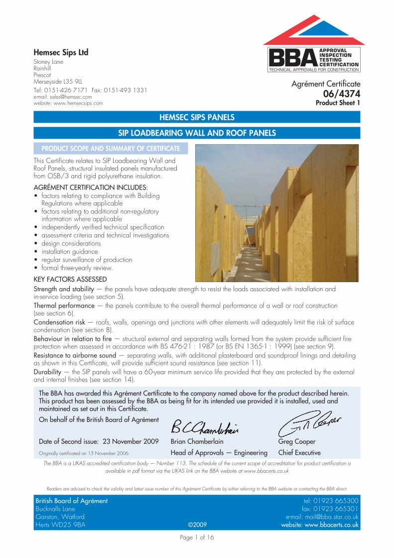
This Certificate relates to SIP Loadbearing Wall and Roof Panels, structural insulated panels manufactured from OSB/3 and rigid polyurethane insulation.
AGRÉMENT CERTIFICATION INCLUDES:factors relating to compliance with Building • Regulations where applicablefactors relating to additional non-regulatory • information where applicableindependently verified technical specification• assessment criteria and technical investigations• design considerations• installation guidance• regular surveillance of production• formal three-yearly review.•
KEY FACTORS ASSESSEDStrength and stability — the panels have adequate strength to resist the loads associated with installation and in-service loading (see section 5).Thermal performance — the panels contribute to the overall thermal performance of a wall or roof construction (see section 6).Condensation risk — roofs, walls, openings and junctions with other elements will adequately limit the risk of surface condensation (see section 8).Behaviour in relation to fire — structural external and separating walls formed from the system provide sufficient fire protection when assessed in accordance with BS 476-21 : 1987 (or BS EN 1365-1 : 1999) (see section 9).Resistance to airborne sound — separating walls, with additional plasterboard and soundproof linings and detailing as shown in this Certificate, will provide sufficient sound resistance (see section 11).Durability — the SIP panels will have a 60-year minimum service life provided that they are protected by the external and internal finishes (see section 14).
Agrément Certificate06/4374
Product Sheet 1
The BBA has awarded this Agrément Certificate to the company named above for the product described herein. This product has been assessed by the BBA as being fit for its intended use provided it is installed, used and maintained as set out in this Certificate.
On behalf of the British Board of Agrément
Date of Second issue: 23 November 2009 Brian Chamberlain Greg Cooper
Originally certificated on 15 November 2006 Head of Approvals — Engineering Chief Executive
Page 2 of 16
In the opinion of the BBA, the SIP Loadbearing Wall and Roof Panels, if used in accordance with the provisions of this Certificate, will meet or contribute to meeting the relevant requirements of the following Building Regulations:
The Building Regulations 2000 (as amended) (England and Wales)
Requirement: A1 LoadingRequirement: A3 Disproportionate collapse
Comment: Walls and roofs constructed from the panels will have sufficient strength and stiffness when designed in accordance with sections 5.1 to 5.3 of this Certificate.
Requirement: B3(1)(2)(3) Internal fire spread (structure)
Comment: The panels, with the requisite lining, can meet this Requirement. See sections 9.1 and 9.6 of this Certificate.
Requirement: C2(c) Resistance to moisture
Comment: The panels can adequately limit the risk of surface condensation and contribute to minimising the risk of interstitial condensation. See sections 7.1 and 7.2 of this Certificate.
Requirement: E1 Protection against sound from other parts of the building and adjoining buildingsRequirement: E2 Protection against sound within a dwelling-house etc.
Comment: When installed with suitable flanking elements, separating walls can adequately meet these Requirements. See sections 11.1 to 11.3 of this Certificate.
Requirement: L1(a)(i) Conservation of fuel and power
Comment: Walls and roofs incorporating the product can meet this requirement. See sections 6.1 to 6.5 of this Certificate.
Requirement: Regulation 7 Materials and workmanship
Comment: The panels are acceptable. See sections 14.1 and 14.2 and the Installation part of this Certificate.
The Building (Scotland) Regulations 2004 (as amended)
Regulation: 8(1)(2) Fitness and durability of materials and workmanship
Comment: The use of the panels satisfies the requirements of this Regulation. See sections 13.1, 13.2, 14.1 and 14.2 and the Installation part of this Certificate.
Regulation: 9 Building standards — constructionStandard: 1.1(a) Structure
Comment: Walls and roofs incorporating the panels will have sufficient strength and stiffness with reference to clause 1.1.1(1), when designed and constructed in accordance with sections 5.1 to 5.3 of this Certificate.
Standard: 2.2 Separation
Comment: Walls using the appropriate lining can achieve a period of fire resistance of ‘medium’ duration, with reference to clauses 2.2.1(1), and 2.2.3(1). See sections 9.1, 9.5 and 9.6 of this Certificate.
Standard: 2.3 Structural protection
Comment: Walls using the appropriate lining can achieve a period of fire resistance of ‘medium’ duration, with reference to clause 2.3.1(1). See sections 9.1, 9.5 and 9.6 of this Certificate.
Standard: 2.4 Cavities
Comment: Walls and roofs using an appropriate cavity barrier can satisfy this Standard, with reference to clauses 2.4.1(1) to 2.4.7(1). See section 9.6 of this Certificate.
Standard: 2.6 Spread to neighbouring buildings
Comment: Walls using the appropriate lining can achieve a period of fire resistance of ‘medium’ duration, with reference to clause 2.6.1(1) of this Standard. See sections 9.1, 9.5 and 9.6 of this Certificate.
Standard: 3.15 Condensation
Comment: The panels can adequately limit the risk of surface condensation and will contribute to minimising the risk of interstitial condensation, with reference to clauses 3.15.1(1) to 3.15.4(1). See sections 7.1, 7.3 and 8 of this Certificate.
Standard: 5.1 Resisting sound transmission to dwellings using appropriate constructions
Comment: When installed with suitable flanking elements, separating walls satisfy this Standard, with reference to clauses 5.1.1(1), 5.1.2(1), 5.1.4(1) and 5.1.6(1). See sections 11.1 to 11.3 of this Certificate.
Standard: 6.1(b) Carbon dioxide emissionsStandard: 6.2 Building insulation envelope
Comment: The panels will enable, or contribute to enabling, a wall to meet clauses 6.2.0(1)(2), 6.2.3(1) and 6.2.4(1)(2) of these Standards. See sections 6.1 to 6.5 of this Certificate.
(1) Technical Handbook (Domestic). (2) Technical Handbook (Non-Domestic).
The Building Regulations (Northern Ireland) 2000 (as amended)
Regulation: B2 Fitness of materials and workmanship
Comment: The panels are acceptable. See sections 14.1 and 14.2 and the Installation part of this Certificate.Regulation: B3(2) Suitability of certain materials
Comment: The products are acceptable. See sections 13.1 and 13.2 of this Certificate.
Regulations
Page 3 of 16
Regulation: C5 Condensation
Comment: The panels can contribute to minimising the risk of interstitial condensation. See sections 7.1, 7.2 and 8 of this Certificate.
Regulation: D1 Stability
Comment: Walls and roofs constructed from the panels will have adequate strength and stiffness to satisfy this Regulation. See sections 5.1 to 5.3 of this Certificate.
Regulation: E4 Internal fire spread — Structure
Comment: The panels can satisfy this Regulation. See sections 9.1 and 9.6 of this Certificate.Regulation: F2 Conservation measuresRegulation: F3(2) Target carbon dioxide Emissions Rate
Comment: The panels will enable, or contribute to enabling, a wall to satisfy these Regulations. See sections 6.1 to 6.5 of this Certificate.
Regulation: G2(1) Separating walls and separating floors
Comment: When installed with suitable flanking elements, separating walls can satisfy this Regulation. See sections 11.1 to 11.3 of this Certificate.
Construction (Design and Management) Regulations 2007Construction (Design and Management) Regulations (Northern Ireland) 2007
Information in this Certificate may assist the client, CDM co-ordinator, designer and contractors to address their obligations under these Regulations.See sections: 2 Delivery and site handling (2.3) and 15 General (15.2).
Non-regulatory Information
NHBC Standards 2008NHBC accepts the use of the SIP Loadbearing Wall and Roof Panels, when installed and used in accordance with this Certificate, in relation to NHBC Standards, Chapter 6, Part 6.2
General
The panels are for use above the damp-proof course in domestic applications up to four storeys high (including room-in-roof) as the loadbearing inner leaf of an external cavity wall. They can also be incorporated as part of a separating wall, as internal walls and in roof constructions.
The panels may also be used as infill panels in multi-storey framed buildings, subject to design constraints on height and method of fixing to structural frames. The Certificate holder should be consulted for suitable details.
It is essential that constructions incorporating the panels are designed in accordance with the Certificate holder’s recommendations and all constructions incorporating the panels assessed and approved by a chartered engineer.
Installation must be carried out by contractors approved by the Certificate holder.
Technical Specification
1 Description1.1 SIP Loadbearing Wall and Roof Panels are structural elements consisting of internal and external skins of oriented strand board, Type 3 (OSB/3) to BS EN 300 : 2006, with an insulation core of closed cell polyurethane (PUR).
1.2 The panels have nominal characteristics of:overall thickness (mm) 100(1), 125, 150, 180OSB thickness (mm) 15insulation thickness (mm) 70, 95, 120, 150insulation density (kg·m–3) 42overall maximum 6.5 x 1.2panel size (m)weight (kg·m–2) 22.1, 23.1, 24.2, 25.5.(1) For use as internal non-loadbearing partition wall only.
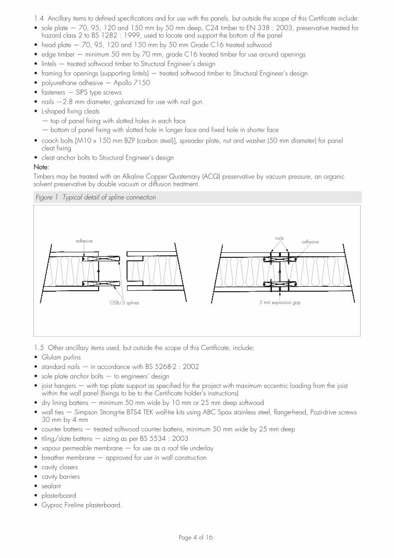
1.3 The panels are connected by the use of OSB/3 splines, 15 mm by 100 mm by 1200 mm (cut to length as required), located in preformed rebates within the PUR core (see Figure 1). Openings are formed with pre-cut panels. Timber framing and inserts for openings and at junctions are installed on site.
Page 4 of 16
1.4 Ancillary items to defined specifications and for use with the panels, but outside the scope of this Certificate include:sole plate — 70, 95, 120 and 150 mm by 50 mm deep, C24 timber to EN 338 : 2003, preservative treated for • hazard class 2 to BS 1282 : 1999, used to locate and support the bottom of the panelhead plate — 70, 95, 120 and 150 mm by 50 mm Grade C16 treated softwood • edge timber — minimum 50 mm by 70 mm, grade C16 treated timber for use around openings• lintels — treated softwood timber to Structural Engineer’s design• framing for openings (supporting lintels) — treated softwood timber to Structural Engineer’s design• polyurethane adhesive — Apollo 7150• fasteners — SIPS type screws• nails —2.8 mm diameter, galvanized for use with nail gun.• L-shaped fixing cleats•
— top of panel fixing with slotted holes in each face — bottom of panel fixing with slotted hole in longer face and fixed hole in shorter face
coach bolts [M10 x 150 mm BZP (carbon steel)], spreader plate, nut and washer (50 mm diameter) for panel • cleat fixingcleat anchor bolts to Structural Engineer’s design •
Note:Timbers may be treated with an Alkaline Copper Quaternary (ACQ) preservative by vacuum pressure, an organic solvent preservative by double vacuum or diffusion treatment.
Figure 1 Typical detail of spline connection
nailsadhesive
3 mm expansion gap
adhesive
OSB/3 splines
1.5 Other ancillary items used, but outside the scope of this Certificate, include:Glulam purlins• standard nails — in accordance with BS 5268-2 : 2002• sole plate anchor bolts — to engineers’ design• joist hangers — with top plate support as specified for the project with maximum eccentric loading from the joist • within the wall panel (fixings to be to the Certificate holder’s instructions)dry lining battens — minimum 50 mm wide by 10 mm or 25 mm deep softwood• wall ties — Simpson Strong-tie BTS4 TEK wall-tie kits using ABC Spax stainless steel, flange-head, Pozi-drive screws • 30 mm by 4 mmcounter battens — treated softwood counter battens, minimum 50 mm wide by 25 mm deep• tiling/slate battens — sizing as per BS 5534 : 2003• vapour permeable membrane — for use as a roof tile underlay• breather membrane — approved for use in wall construction• cavity closers• cavity barriers• sealant• plasterboard• Gyproc Fireline plasterboard.•
Page 5 of 16
1.6 The detail of types of internal wall that can be constructed from the panels is given in Figure 2.
Figure 2 Internal wall specification
(a) internal wall(non-leadbearing)
100
175
12.5 mm plasterboard
25 x 50 mm batten
(dimensions in mm)
(b) internal wall acoustic(non-loadbearing)
125
225
12.5 mm plasterboard
12.5 mm Gyproc Firelineplasterboard
25 x 50 mm batten
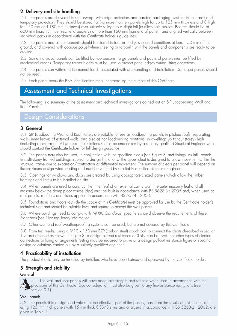
1.7 The panels may also be used as infill panels in multi-storey framed buildings, subject to design limitations (see section 3.2). The panels are attached to the frame using L-shaped metal fixing cleats, fixed to the top and bottom of the infill panel. The top cleat has slotted holes in each leg, to allow for movements within the structural frame due to expansion/contraction or differential movement, and to allow for the insertion of a compressible sealant or insulation between panel head and frame. The bottom cleat has a slotted hole in the longer leg to allow any lateral movement necessary for alignment with adjacent panels, but a fixed hole in the shorter face. Generally coach bolts M10 x 150 mm BZP (carbon steel with 50 mm washer) are used to attach the cleats to the top and bottom of the infill panels. Typically anchor bolts are used to attach the cleats to a concrete slab. A typical example of the method of fixing is shown in Figure 3.
Figure 3 Typical example of panel fixing using cleats
Page 6 of 16
2 Delivery and site handling2.1 The panels are delivered in shrink-wrap, with edge protectors and banded packaging used for initial transit and temporary protection. They should be stored flat (no more than ten panels high for up to 125 mm thickness and 8 high for 150 mm and 180 mm thickness) over suitable stillage to a slight fall (to allow rain run-off). Bearers should be at 600 mm (maximum) centres, (end bearers no more than 150 mm from end of panel), and aligned vertically between individual packs in accordance with the Certificate holder’s guidelines.
2.2 The panels and all components should be stored inside, or in dry, sheltered conditions at least 150 mm off the ground, and covered with opaque polyethylene sheeting or tarpaulin until the panels and components are ready to be erected.
2.3 Some individual panels can be lifted by two persons, large panels and packs of panels must be lifted by mechanical means. Temporary timber blocks must be used to protect panel edges during lifting operations.
2.4 The panels can withstand the normal loads associated with site handling and installation. Damaged panels should not be used.
2.5 Each panel bears the BBA identification mark incorporating the number of this Certificate.
Assessment and Technical Investigations
The following is a summary of the assessment and technical investigations carried out on SIP Loadbearing Wall and Roof Panels.
Design Considerations
3 General3.1 SIP Loadbearing Wall and Roof Panels are suitable for use as loadbearing panels in pitched roofs, separating walls, inner leaves of external walls, and also as non-loadbearing partitions, in dwellings up to four storeys high (including room-in-roof). All structural calculations should be undertaken by a suitably qualified Structural Engineer who should contact the Certificate holder for full design guidance.
3.2 The panels may also be used, in conjunction with the specified cleats (see Figure 3) and fixings, as infill panels in multi-storey framed buildings, subject to design limitations. The upper cleat is designed to allow movement within the structural frame due to expansion/contraction or differential movement. The number of cleats per panel will depend on the maximum design wind loading and must be verified by a suitably qualified Structural Engineer.
3.3 Openings for windows and doors are created by using appropriately sized panels which allow the timber framings and lintels to be installed on site.
3.4 When panels are used to construct the inner leaf of an external cavity wall, the outer masonry leaf and all masonry below the damp-proof course (dpc) must be built in accordance with BS 5628-3 : 2005 and, when used as roof panels, roof tiles and slates applied in accordance with BS 5534 : 2003.
3.5 Foundations and floors (outside the scope of this Certificate) must be approved for use by the Certificate holder’s technical staff and should be suitably level and square to accept the wall panels.
3.6 Where buildings need to comply with NHBC Standards, specifiers should observe the requirements of these Standards (see Non-regulatory Information).
3.7 Other wall and roof weatherproofing systems can be used, but are not covered by this Certificate.
3.8 From test results, using a M10 x 150 mm BZP (carbon steel) coach bolt to connect the cleats described in section 1.7 and detailed as shown in Figure 3, a design pull-out resistance of 3 kN can be used. For other types of cleated connections or fixing arrangements testing may be required to arrive at a design pull-out resistance figure or specific design calculations carried out by a suitably qualified engineer.
4 Practicability of installationThe product should only be installed by installers who have been trained and approved by the Certificate holder.
5 Strength and stabilityGeneral
5.1 The wall and roof panels will have adequate strength and stiffness when used in accordance with the provisions of this Certificate. Due consideration must also be given to any fire-resistance restrictions (see section 9.1).
Wall panels5.2 The permissible design load values for the effective span of the panels, based on the results of tests undertaken using 125 mm thick panels with 15 mm thick OSB/3 skins and analysed in accordance with BS 5268-2 : 2002, are given in Table 1.
Page 7 of 16
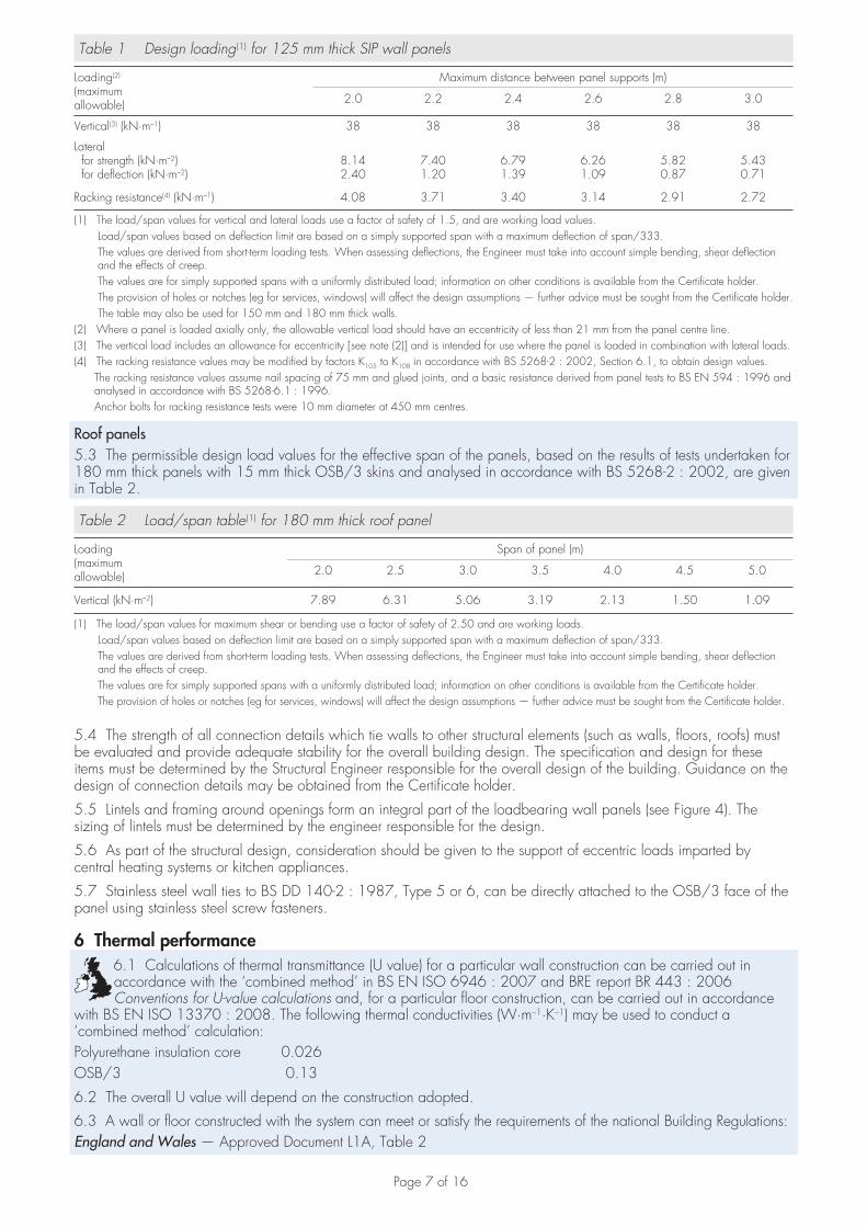
Table 1 Design loading (1) for 125 mm thick SIP wall panels
Loading(2)
(maximumallowable)
Maximum distance between panel supports (m)
2.0 2.2 2.4 2.6 2.8 3.0
Vertical(3) (kN·m–1) 38 38 38 38 38 38
Lateral for strength (kN·m–2) for deflection (kN·m–2)
8.142.40
7.401.20
6.791.39
6.261.09
5.820.87
5.430.71
Racking resistance(4) (kN·m–1) 4.08 3.71 3.40 3.14 2.91 2.72
(1) The load/span values for vertical and lateral loads use a factor of safety of 1.5, and are working load values. Load/span values based on deflection limit are based on a simply supported span with a maximum deflection of span/333. The values are derived from short-term loading tests. When assessing deflections, the Engineer must take into account simple bending, shear deflection
and the effects of creep. The values are for simply supported spans with a uniformly distributed load; information on other conditions is available from the Certificate holder. The provision of holes or notches (eg for services, windows) will affect the design assumptions — further advice must be sought from the Certificate holder. The table may also be used for 150 mm and 180 mm thick walls.(2) Where a panel is loaded axially only, the allowable vertical load should have an eccentricity of less than 21 mm from the panel centre line.(3) The vertical load includes an allowance for eccentricity [see note (2)] and is intended for use where the panel is loaded in combination with lateral loads.(4) The racking resistance values may be modified by factors K105 to K108 in accordance with BS 5268-2 : 2002, Section 6.1, to obtain design values. The racking resistance values assume nail spacing of 75 mm and glued joints, and a basic resistance derived from panel tests to BS EN 594 : 1996 and
analysed in accordance with BS 5268-6.1 : 1996. Anchor bolts for racking resistance tests were 10 mm diameter at 450 mm centres.
Roof panels5.3 The permissible design load values for the effective span of the panels, based on the results of tests undertaken for 180 mm thick panels with 15 mm thick OSB/3 skins and analysed in accordance with BS 5268-2 : 2002, are given in Table 2.
Table 2 Load/span table (1) for 180 mm thick roof panel
Loading(maximumallowable)
Span of panel (m)
2.0 2.5 3.0 3.5 4.0 4.5 5.0
Vertical (kN·m–2) 7.89 6.31 5.06 3.19 2.13 1.50 1.09
(1) The load/span values for maximum shear or bending use a factor of safety of 2.50 and are working loads. Load/span values based on deflection limit are based on a simply supported span with a maximum deflection of span/333. The values are derived from short-term loading tests. When assessing deflections, the Engineer must take into account simple bending, shear deflection
and the effects of creep. The values are for simply supported spans with a uniformly distributed load; information on other conditions is available from the Certificate holder. The provision of holes or notches (eg for services, windows) will affect the design assumptions — further advice must be sought from the Certificate holder.
5.4 The strength of all connection details which tie walls to other structural elements (such as walls, floors, roofs) must be evaluated and provide adequate stability for the overall building design. The specification and design for these items must be determined by the Structural Engineer responsible for the overall design of the building. Guidance on the design of connection details may be obtained from the Certificate holder.
5.5 Lintels and framing around openings form an integral part of the loadbearing wall panels (see Figure 4). The sizing of lintels must be determined by the engineer responsible for the design.
5.6 As part of the structural design, consideration should be given to the support of eccentric loads imparted by central heating systems or kitchen appliances.
5.7 Stainless steel wall ties to BS DD 140-2 : 1987, Type 5 or 6, can be directly attached to the OSB/3 face of the panel using stainless steel screw fasteners.
6 Thermal performance6.1 Calculations of thermal transmittance (U value) for a particular wall construction can be carried out in accordance with the ‘combined method’ in BS EN ISO 6946 : 2007 and BRE report BR 443 : 2006 Conventions for U-value calculations and, for a particular floor construction, can be carried out in accordance
with BS EN ISO 13370 : 2008. The following thermal conductivities (W·m–1·K–1) may be used to conduct a ‘combined method’ calculation:Polyurethane insulation core 0.026OSB/3 0.13
6.2 The overall U value will depend on the construction adopted.
6.3 A wall or floor constructed with the system can meet or satisfy the requirements of the national Building Regulations:England and Wales — Approved Document L1A, Table 2
Page 8 of 16
Scotland — Mandatory Standard 6.2, clause 6.2.1(1), Table Maximum U-values for building elements of the insulation envelope(1) Technical Handbook (Domestic).
Northern Ireland — Technical Booklet F1, Table 2.2.
6.4 Junctions with other elements should be designed to limit heat loss. Detailed guidance in this respect and on limiting heat loss by air infiltration can be found in:England and Wales — Limiting thermal bridging and air leakage: Robust construction details for dwellings and similar buildings TSO 2002 or Accredited Construction Details (version 1.0)Scotland — Accredited Construction Details (Scotland)Northern Ireland — Accredited Construction Details (version 1.0)
6.5 For existing buildings that are being extended or converted, walls will be acceptable where they achieve or exceed the relevant U value given in Table 3 or 4 and junctions and openings comply with BRE report BR 262 : 2002, Thermal insulation; avoiding risks, Section 5.5.
Table 3 Typical design U values — England, Wales and Northern Ireland
U value (W·m–2·K–1) Construction type
0.25 Mean for floors
0.3 Mean for new extensions(1)
0.35 ‘notional’ mean in SAP and SBEM and limit mean for new-build
0.35 Limit mean for replacement(1), renovation(1) and retained(1) walls
0.70 Individual limit for new-build and flexible approaches(1)
(1) Alternative/flexible approaches are given in the relevant document supporting the national Building Regulations.
Table 4 Typical design U values — Scotland
U value (W·m–2·K–1) Construction type
0.200.25
‘notional’ mean for dwellings in SAP and the ‘simplified’ approach: – solid fuel packages – other fuels, packages
0.25 Mean for floors
0.27 Limit mean for new extensions, conversions(1), alterations and reconstructions
0.30 ‘notional’ mean for non-domestic in SBEM and limit mean for new-build
0.70 Individual limit for new-build and flexible approaches(1)
(1) Alternative/flexible approaches are given in the relevant document supporting the national Building Regulations.
6.6 Typical U values for building elements, calculated in accordance with BS EN ISO 6946 : 2007 and BRE report BR 443 : 2006, are given in Table 5.
Table 5 Typical U values
Element Panel thickness(mm)
U value(W·m–2·K–1)
External wall(1) 125150180
0.220.180.15
Roof(2) 180 0.16
(1) Based on panels lined as described in Table 6 with a 50 mm wide cavity and brick outer leaf.(2) Based on panels lined internally with 12.5 mm thick plasterboard on battens with a slated or tiled exterior.
7 Air leakage7.1 Buildings can achieve adequate resistance to heat loss by air infiltration provided there is effective sealing around junctions between units during site assembly. Care should be taken to ensure that junctions with other elements and openings comply with the relevant guidance for airtightness as given in the relevant documents
referred to in section 6.4.
7.2 In England, Wales and Northern Ireland, completed buildings are subject to pre-completion testing for airtightness in accordance with the requirements of Approved Documents L1A and L2B (section 20B), Technical Booklet F1 (sections 2.46 to 2.54) and Technical Booklet F2 (sections 2.54 to 2.61) respectively.
7.3 Completed dwellings in Scotland are only subject to pre-completion airtightness testing if the target air permeability of the proposed building is less than 10 m3·h–1·m–2 and 15 m3·h–1·m–2 and if the designer does not wish to use the 15 m3·h–1·m–2 default figure in the proposed dwelling, in accordance with the Technical
Handbook (Domestic).
Page 9 of 16
7.4 The risk of interstitial condensation in both the external walling and the roofing is greatest when the building is drying out after construction. Guidance on preventing condensation is given in BRE Digest 369 Interstitial condensation and fabric degradation and BRE report BR 262 : 2002.
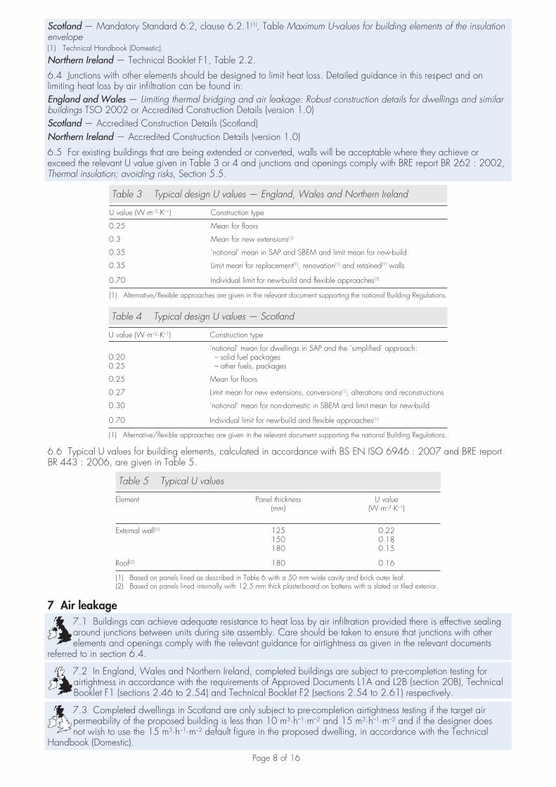
8 Condensation riskProvided the panels are properly sealed together as detailed in section 7.1, the risk of surface and interstitial condensation under normal domestic use will be minimal (see Figure 4 and the Installation part of this Certificate).
Figure 4 Typical opening details
(b) section through window jamb detail
dpc and cavity closer
stainless steelwall tie
breathermembrane
125 mm Hemsecpanel
50 mm x 10 mm vertical counterbattens at 600 mm centres
(1) Minimum frame overlap of window to be 30 mm.Minimum resistance of part of closer overlapped by
frame to be 0.45 m K W .2 –1· ·
breathermembrane
steel lintel
silicone sealant
12.5 mm GyprocFireline
12.5 mm GyprocWallboard
silicone sealant
cavity closer orinsulated lintel
(1)
(a) section through window head and sill detail
silicone sealant
dpc and cavity closer(1)
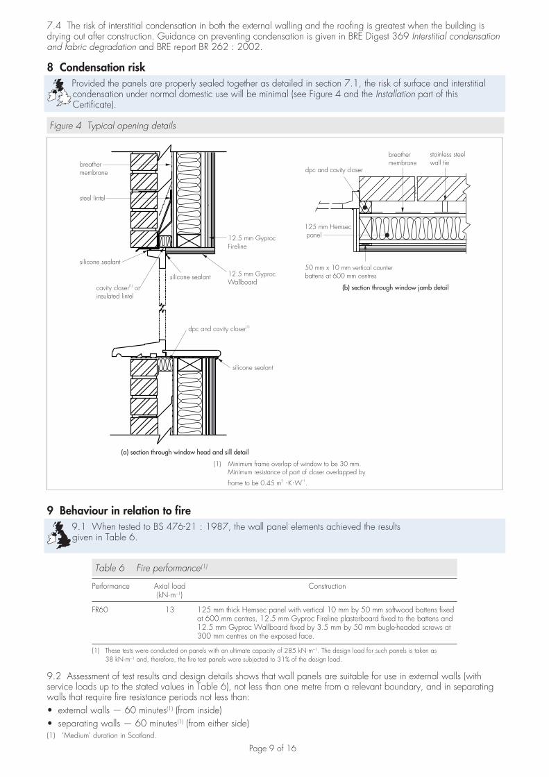
9 Behaviour in relation to fire9.1 When tested to BS 476-21 : 1987, the wall panel elements achieved the results given in Table 6.
Table 6 Fire performance(1)
Performance Axial load(kN·m–1)
Construction
FR60 13 125 mm thick Hemsec panel with vertical 10 mm by 50 mm softwood battens fixed at 600 mm centres, 12.5 mm Gyproc Fireline plasterboard fixed to the battens and 12.5 mm Gyproc Wallboard fixed by 3.5 mm by 50 mm bugle-headed screws at 300 mm centres on the exposed face.
(1) These tests were conducted on panels with an ultimate capacity of 285 kN·m–1. The design load for such panels is taken as 38 kN·m–1 and, therefore, the fire test panels were subjected to 31% of the design load.
9.2 Assessment of test results and design details shows that wall panels are suitable for use in external walls (with service loads up to the stated values in Table 6), not less than one metre from a relevant boundary, and in separating walls that require fire resistance periods not less than:
external walls — 60 minutes• (1) (from inside)separating walls — 60 minutes• (1) (from either side)
(1) ‘Medium’ duration in Scotland.
Page 10 of 16
9.3 The OSB/3 panel skins have a Class 3(2) surface spread of flame designation.(2) ‘High risk’ in Scotland
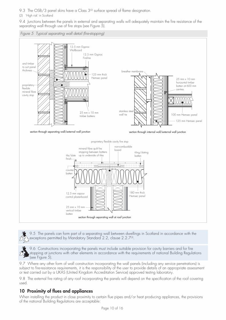
9.4 Junctions between the panels in external and separating walls will adequately maintain the fire resistance of the separating wall through use of fire stops (see Figure 5).
Figure 5 Typical separating wall detail (fire-stopping)
section through internal wall/external wall junction
25 mm x 10 mmhorizontal timberbatten at 600 mmcentres
stainless steelwall tie 100 mm Hemsec panel
125 mm Hemsec panel
breather membrane
section through separating wall/external wall junction
25 mm x 10 mmtimber battens
125 mm thickHemsec panel
12.5 mm GyprocWallboard
12.5 mm GyprocFireline
end timberto suit panelthickness
proprietaryflexiblemineral fibrecavity stop
section through separating wall at roof junction
proprietary flexible cavity fire stop
non-combustibleboard
tiling/slatingbattentile/slate
finish
12.5 mm vapourcontrol plasterboard
25 mm x 10 mmvertical timberbatten
counterbatten
180 mm thickHemsec panel
mineral fibre quilt firestopping between battensup to underside of tiles
9.5 The panels can form part of a separating wall between dwellings in Scotland in accordance with the exceptions permitted by Mandatory Standard 2.2, clause 2.2.7(3).
9.6 Constructions incorporating the panels must include suitable provision for cavity barriers and for fire stopping at junctions with other elements in accordance with the requirements of national Building Regulations (see Figure 5).
9.7 Where any other form of wall construction incorporating the wall panels (including any service penetrations) is subject to fire-resistance requirements, it is the responsibility of the user to provide details of an appropriate assessment or test carried out by a UKAS (United Kingdom Accreditation Service) approved testing laboratory.
9.8 The external fire rating of any roof incorporating the panels will depend on the specification of the roof covering used.
10 Proximity of flues and appliancesWhen installing the product in close proximity to certain flue pipes and/or heat producing appliances, the provisions of the national Building Regulations are acceptable:
Page 11 of 16
England and Wales — Approved Document JScotland — Mandatory Standard 3.18, clauses 3.18.1(1) to 3.18.6(1)
(1) Technical Handbook (Domestic)
Northern Ireland — Technical Booklet L.
11 Resistance to airborne sound11.1 In England and Wales, separating walls are subject to pre-completion testing in accordance with Approved Document E, Section 1. A similar approach is described in the Scottish Building Standards, Mandatory Standard 5.1, clause 5.1.2(1).
(1) Technical Handbook (Domestic).
11.2 Laboratory test data relating to measurements made in accordance with BS EN ISO 140-3 : 1995 indicate that the wall constructions detailed in Tables 7, 8 and 9 have the resistances to airborne sound transmission stated.
Table 7 Airborne sound insulation (dB) — Laboratory test results
Construction (dB)
Separating wall (Figure 4) Rw (Ci;Ctr) = 57 (–2;–7)∴ Rw–Ctr = 50
Internal wall (Figure 2) Rw >40
Table 8 Airborne sound insulation (dB). Deemed to satisfy — England and Wales
Construction Mean value (dB)
Separating walls — dwelling-houses and flats DnT,w+Ctr�45
Internal walls — between a bedroom or a WC and other rooms Rw �40
Table 9 Airborne sound insulation (dB). Deemed to satisfy — Scotland and Northern Ireland
Construction Mean value (dB)
Separating walls — dwelling-houses and flats DnT,w �53
11.3 The test data given in section 11.2 (Tables 7, 8 and 9) indicate that, in England and Wales, the wall constructions can provide satisfactory resistance to airborne sound transmission within a dwelling for walls between a WC or bathroom and another room.
11.4 It is essential that care is taken in design and during installation to avoid direct paths for airborne sound transmission and to minimise paths for flanking sound transmission.
12 Damp-proofing and weathertightness12.1 When the panels are used to form the inner leaf of an external cavity wall, the outer leaf must be designed and constructed in accordance with BS 5628-3 : 2005 incorporating damp-proof courses and cavity trays positioned in accordance with the latter Code. A breather membrane is required with this form of construction.
12.2 When used with other outer leaf construction, cladding or render systems, the final weather resistance of the building is dependent upon the efficient positioning and sealing of all joints. The guidance given in BRE report BR 262 : 2002, Section 3, should be followed with regard to rain penetration in that the designer selects a construction appropriate to the local wind-driven rain index, paying due regard to the design detailing, workmanship and materials to be used.
12.3 Roofing should be in accordance with BS 5534 : 2003 to ensure moisture is prevented from coming into contact with the roof panels or construction quoted in this Certificate.
12.4 The performance of windows and doors installed within the panels is not covered by this Certificate.
13 Maintenance and repair13.1 Although maintenance is not envisaged for the panels, regular checks should be carried out on the finishes to ensure that any damage is detected and repaired as soon as possible.
13.2 Minor repairs can be carried out to the panels prior to erection in accordance with the Certificate holder’s construction manual.
14 Durability14.1 The panels will have comparable durability to that of OSB/3 to BS EN 300 : 2006. Provided the installation remains weathertight and damp-proof, a life of at least 60 years may therefore be expected.
14.2 Timber used in areas that could be at risk, eg screed rails, should be preservative-treated in accordance with the recommendations given in BS 1282 : 1999.
Page 12 of 16
Installation
15 General15.1 Erection of SIP Loadbearing Wall and Roof Panels must comply with the details given in the Certificate holder’s construction manual and the provisions of this Certificate.
15.2 The main contractor must ensure that the accuracy of the foundation is in accordance with the Certificate holder’s instructions. In particular, the following details must be within the tolerance of ± 5 mm:
the level of the foundation or other bearing support• the overall width and length of the building footprint• the diagonals used for checking the overall squareness of the building.•
Wall infill panelsWhen used as an infill panel, the main contractor must ensure that the accuracy of the structural frame is in accordance with the Certificate holder’s acceptable tolerances, ie:
panels to be held in place with the specified brackets• a 25 mm gap to be left at the head of the infill panel to allow for expansion/differential movement. The gap should • be filled with compressed mineral wool insulation.
Guidance in the procedure for installing the infill panels is limited due to the variations in the structural frame construction and detailing. Erection methods for lifting the infill panels into place and the specification and design of brackets, fixings and tolerances will therefore need to be determined by the project engineer for each structure in which the infill panels are used.
16 ProcedureFoundation construction16.1 A suitable damp-proof course (dpc) is laid on top of the foundation.
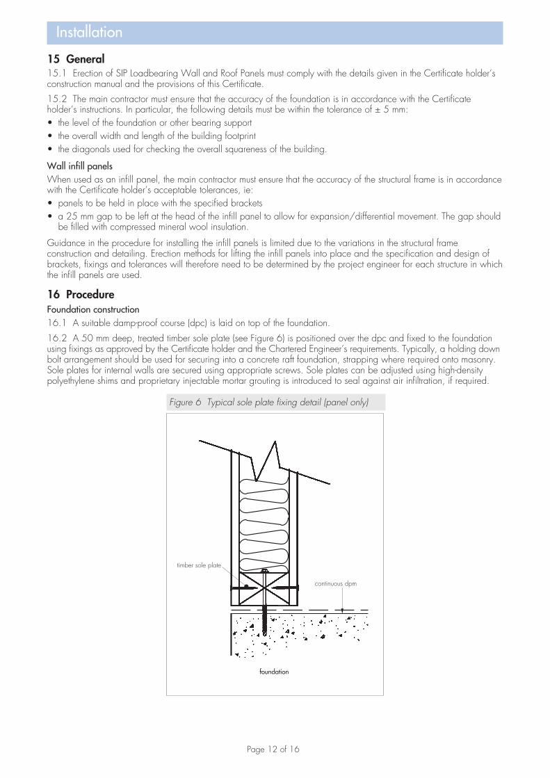
16.2 A 50 mm deep, treated timber sole plate (see Figure 6) is positioned over the dpc and fixed to the foundation using fixings as approved by the Certificate holder and the Chartered Engineer’s requirements. Typically, a holding down bolt arrangement should be used for securing into a concrete raft foundation, strapping where required onto masonry. Sole plates for internal walls are secured using appropriate screws. Sole plates can be adjusted using high-density polyethylene shims and proprietary injectable mortar grouting is introduced to seal against air infiltration, if required.
Figure 6 Typical sole plate fixing detail (panel only)
Page 13 of 16
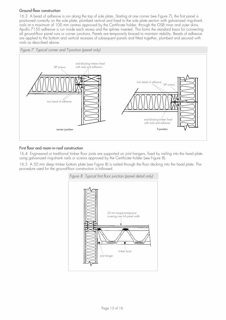
Ground-floor construction16.3 A bead of adhesive is run along the top of sole plate. Starting at one corner (see Figure 7), the first panel is positioned correctly on the sole plate, plumbed vertical and fixed to the sole plate section with galvanized ring-shank nails at a maximum of 100 mm centres approved by the Certificate holder, through the OSB inner and outer skins. Apollo 7150 adhesive is run inside each recess and the splines inserted. This forms the standard basis for connecting all ground-floor panel runs or corner junctions. Panels are temporarily braced to maintain stability. Beads of adhesive are applied to the bottom and vertical recesses of subsequent panels and fitted together, plumbed and secured with nails as described above.
Figure 7 Typical corner and T-junction (panel only)
corner junction
end blocking timbers fixedwith nails and adhesiveSIP screws
twin bead of adhesive
SIP screwstwin bead of adhesive
end blocking timber fixedwith nails and adhesive
T-junction
First floor and room-in-roof construction16.4 Engineered or traditional timber floor joists are supported on joist hangers, fixed by nailing into the head plate using galvanized ring-shank nails or screws approved by the Certificate holder (see Figure 8).
16.5 A 50 mm deep timber bottom plate (see Figure 8) is nailed through the floor decking into the head plate. The procedure used for the ground-floor construction is followed.
Figure 8 Typical first floor junction (panel detail only)
Page 14 of 16
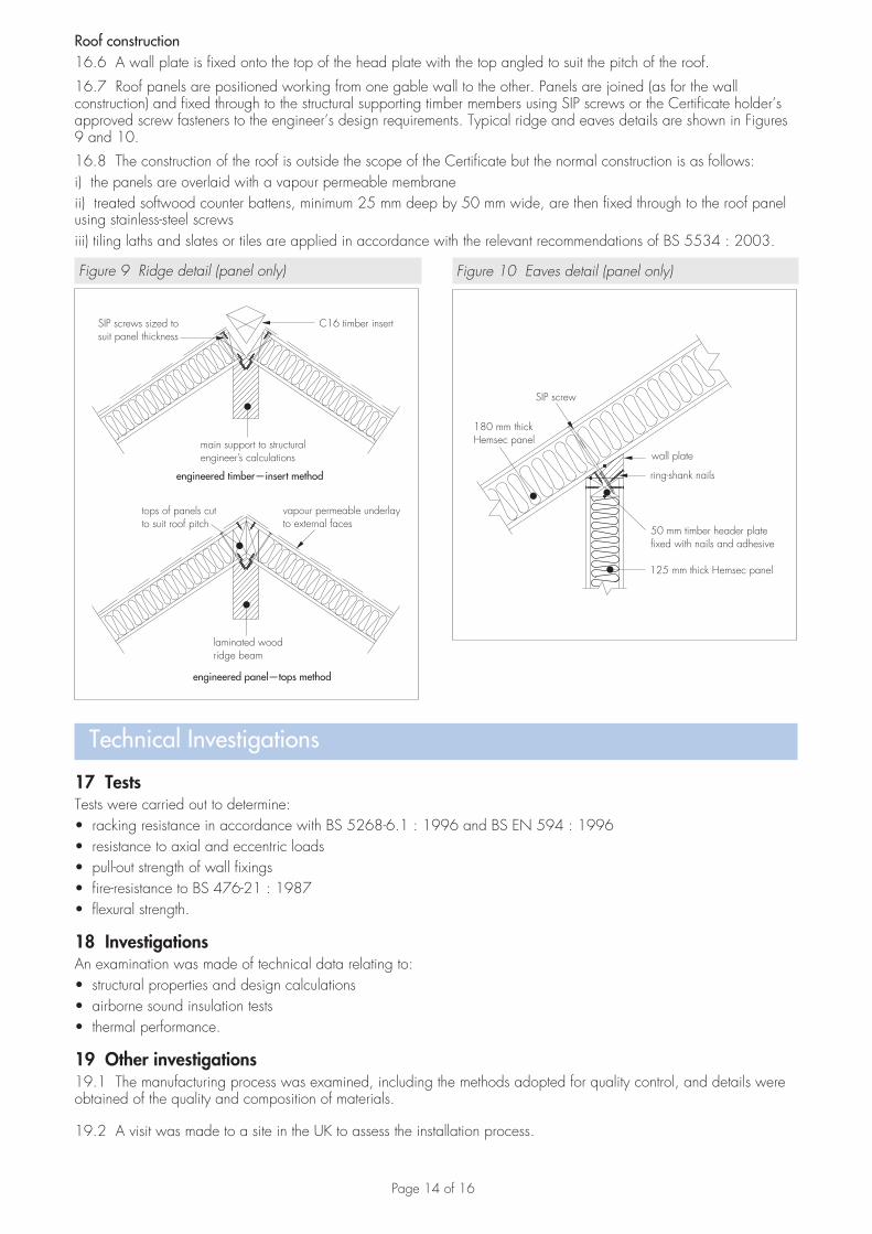
Roof construction16.6 A wall plate is fixed onto the top of the head plate with the top angled to suit the pitch of the roof.
16.7 Roof panels are positioned working from one gable wall to the other. Panels are joined (as for the wall construction) and fixed through to the structural supporting timber members using SIP screws or the Certificate holder’s approved screw fasteners to the engineer’s design requirements. Typical ridge and eaves details are shown in Figures 9 and 10.
16.8 The construction of the roof is outside the scope of the Certificate but the normal construction is as follows: i) the panels are overlaid with a vapour permeable membraneii) treated softwood counter battens, minimum 25 mm deep by 50 mm wide, are then fixed through to the roof panel using stainless-steel screwsiii) tiling laths and slates or tiles are applied in accordance with the relevant recommendations of BS 5534 : 2003.
Figure 9 Ridge detail (panel only)
Technical Investigations
17 TestsTests were carried out to determine:
racking resistance in accordance with BS 5268-6.1 : 1996 and BS EN 594 : 1996• resistance to axial and eccentric loads• pull-out strength of wall fixings• fire-resistance to BS 476-21 : 1987• flexural strength.•
18 InvestigationsAn examination was made of technical data relating to:
structural properties and design calculations• airborne sound insulation tests• thermal performance.•
19 Other investigations19.1 The manufacturing process was examined, including the methods adopted for quality control, and details were obtained of the quality and composition of materials.
19.2 A visit was made to a site in the UK to assess the installation process.
Figure 10 Eaves detail (panel only)
Page 15 of 16
Bibliography
BS 476-21 : 1987 Fire tests on building materials and structures — Methods for determination of the fire resistance of loadbearing elements of construction
BS EN 1365-1 : 1999 Fire resistance tests for loadbearing elements — Walls
BS 1282 : 1999 Wood preservatives — Guidance on choice, use and application
BS 5268-2 : 2002 Structural use of timber — Code of practice for permissible stress design, materials and workmanshipBS 5268-3 : 2006 Structural use of timber — Code of practice for trussed rafter roofsBS 5268-6.1 : 1996 Structural use of timber — Code of practice for timber frame walls — Dwellings not exceeding four storeys
BS 5534 : 2003 Code of practice for slating and tiling (including shingles)
BS 5628-3 : 2005 Code of practice for the use of masonry — Materials and components, design and workmanship
BS DD 140-2 : 1987 Wall ties — Recommendations for design of wall ties
BS EN 300 : 2006 Oriented Strand Boards (OSB) — Definitions, classification and specifications
BS EN 338 : 2003 Structural timber — Strength classes
BS EN 594 : 1996 Timber structures — Test methods — Racking strength and stiffness of timber frame wall panels
BS EN ISO 140-3 : 1995 Acoustics — Measurement of sound insulation in buildings and of building elements — Laboratory measurement of airborne sound insulation of building elements
BS EN ISO 6946 : 2007 Building components and building elements — Thermal resistance and thermal transmittance — Calculation method
BS EN ISO 13370 : 2008 Thermal performance of buildings — Heat transfer via the ground — Calculation methods
Page 16 of 16
Conditions of Certification
20 Conditions20.1 This Certificate:
relates only to the product/system that is named and described on the front page• is granted only to the company, firm or person named on the front page — no other company, firm or person may • hold or claim any entitlement to this Certificateis valid only within the UK• has to be read, considered and used as a whole document —• it may be misleading and will be incomplete to be selectiveis copyright of the BBA• is subject to English law.•
20.2 Publications and documents referred to in this Certificate are those that the BBA deems to be relevant at the date of issue or re-issue of this Certificate and include any: Act of Parliament; Statutory Instrument; Directive; Regulation; British, European or International Standard; Code of Practice; manufacturers’ instructions; or any other publication or document similar or related to the aforementioned.
20.3 This Certificate will remain valid for an unlimited period provided that the product/system and the manufacture and/or fabrication including all related and relevant processes thereof:
are maintained at or above the levels which have been assessed and found to be satisfactory by the BBA• continue to be checked as and when deemed appropriate by the BBA under arrangements that it will determine• are reviewed by the BBA as and when it considers appropriate.•
20.4 In granting this Certificate, the BBA is not responsible for:the presence or absence of any patent, intellectual property or similar rights subsisting in the product/system or any • other product/systemthe right of the Certificate holder to manufacture, supply, install, maintain or market the product/system• individual installations of the product/system, including the nature, design, methods and workmanship of or related • to the installationthe actual works in which the product/system is installed, used and maintained, including the nature, design, • methods and workmanship of such works.
20.5 Any information relating to the manufacture, supply, installation, use and maintenance of this product/system which is contained or referred to in this Certificate is the minimum required to be met when the product/system is manufactured, supplied, installed, used and maintained. It does not purport in any way to restate the requirements of the Health & Safety at Work etc Act 1974, or of any other statutory, common law or other duty which may exist at the date of this Certificate; nor is conformity with such information to be taken as satisfying the requirements of the 1974 Act or of any statutory, common law or other duty of care. In granting this Certificate, the BBA does not accept responsibility to any person or body for any loss or damage, including personal injury, arising as a direct or indirect result of the manufacture, supply, installation, use and maintenance of this product/system.
British Board of Agrément tel: 01923 665300Bucknalls Lane fax: 01923 665301Garston, Watford e-mail: [email protected] WD25 9BA website: www.bbacerts.co.uk©2009