Embed Size (px)
Citation preview

www.pce-consultants.com
Prequalifi cation Documents
2

www.pce-consultants.com
Prequalifi cation Documents
3
technical service roots. Since those early days, PCE has stayed true to what we have always believed in – that our clients.and employees deserve our best – and this is still the foundation for our dynamic domestic and global operations todayWe believe our success is largely due to our unwavering commitment to provide our clients and employees with their ownunique opportunities to thrive. We do this by ensuring that our clients’ expectations and needs are our priorities and weprovide our employees with continual opportunities for developmentOur roots are important to us. As we evolve and grow, we understand that maintaining the integrity of our past througha commitment to quality service, employee appreciation and delivering innovative, practical solutions to our clients is thekey to our successWe are confident about the future of PCE as we look toward new opportunities and continued growth in our many fields
challenging career opportunitiesOn behalf of PCE, thank you for taking the time to learn more about us
Waleed Elsweedy
CEO Statement

www.pce-consultants.com
Prequalifi cation Documents
4

www.pce-consultants.com
Prequalifi cation Documents
5
- Organizational Profi le 09- About PCE 11- Standing and Soundness 15
- Organizational Structure 17 - Overview 18 - Corporate Organizational Structure, PCE 19
- Understanding and Methodology Statement 21 - Architecture Methodology 23 - Structure Methodology 31 - Electrical Methodology 37 - HVAC Methodology 41 - Mechanical Methodology 45 - Infrastructure Methodology 49 - Landscape Methodology 53
- Precedents and Work Experience 61
Hospitals -Military Hospital

www.pce-consultants.com
Prequalifi cation Documents
6
-Riyadh Hospital -Wady Elnile Hospital -Hael Hospital -Marina Medical Center- Marina -AlAbasia-Hospital -Najaf Hospital -Samawa Hospital -El Safa Hospital -Neuro Spine Hospital at 6Th Of October -Doctor Omar Kotb Lab
Pharmaceutical Industries -Marcyrl Factory -L’OREAL Cosmetic plant -Delta Pharma Factory -LIPTIS Factory for Pharmaceutical
Industrial -Taghleef Factory-6th October -Argo Factory- 6th October -Fine Factory- 6th October -Dabur Factory-10th of Ramadan
Infrastructure -King Khaled University Campus in Bisha -King Khaled University Campus in Abha -Misr Insurance Club-Mokattam-National Housing Project- 6th October-National Housing Project-Borg-El Arab
-National Housing Project-Sohag -Sharming Inn Villas- Sharm El Shikh -Lhacienda-Ras Sedr -Gaca Lands Usage Study And Building Design
Commercial and Residential -National Bank of Egypt -Fifth District

www.pce-consultants.com
Prequalifi cation Documents
7
-Bank Faisal-Ismailia Branch -Landmark -Fifth District -ABHA Residential and Administrative Building -Gnena-Administrative and commercial building-Phase II -Azmeel’s Offi ce Building -Jedda -Riyadh Public Transport Control Center -Najeed Offi ces Building -Wady Elnile Admin Building -Azmeel’s Offi ce Building -Jedda
www.pce-consultants.com
Prequalifi cation Documents
8
www.pce-consultants.com
Prequalifi cation Documents
9
- Organization Profi le - About PCE - Standing and Soundness
Organization Profi le

www.pce-consultants.com
Prequalifi cation Documents
10
www.pce-consultants.com
Prequalifi cation Documents
11
About PCE
www.pce-consultants.com
Prequalifi cation Documents
12
About PCEWho We Are
PCE PRECISION CONSULTING ENGINEERING is aprofessional offi ce for consultancy and developmentfounded in 2008 in Egypt offering a wide range of technicalservices; leaded by a group of highly qualifi ed consultantsand technical engineers, whose expertise in engineeringprojects covers all major disciplines of design andconstruction.
PCE has successfully accomplished a long list of projects, inEgypt, Africa and the Middle East, covering all major fi elds ofengineering. This covers architecture/landscaping, physicalplanning, Public and industrial buildings, civil engineeringand utilities, electromechanical engineering, tunneling,airports and transportation facilities,. Profi les of selectedPCE indicative projects, completed or currently underdesign and construction are included hereinafter.
The services rendered by the fi rm cover almost the fullrange of professional engineering services. These includeproject identifi cation, pre-feasibility and feasibility studies,properties and sites appraisal, selection of new sites forprojects, design and detailed engineering of projects,construction management and procurement services,construction supervision and inspection services, qualitycontrol, and training of personnel.
Market Sectors
Studies/Planning
Engineering Services
Construction Services
www.pce-consultants.com
Prequalifi cation Documents
13
FIELDS OF ACTIVITIES
Commercial and Airport Terminal Buildings)
Mission Statement
Precision Consulting Engineering is committed to offer state-of-the-art services to all assignments, throughout the wholeproject life-cycle. We are dedicated to deliver Clients’ needsand exceed expectations by promising timely deadlines,while observing budgets and assuring quality.
Vision Statement
PCE aspires to be one of the top fi ve multi-disciplinaryengineering consultancy fi rm in the middle east with satisfi edClients and project portfolio from the entire region.
Purpose and Core Values
Our purpose — to create, enhance and sustain theworld’s built, natural and social environments — unitesprofessionals working corroboratively across a broad rangeof disciplines.
Our core values recognize that our business success isfounded upon a commitment to certain principles.
Integrity
We succeed by doing things the right way, with respect toethics, laws, standards of quality, and each other.
Employees
Our product is our people — our knowledge, skills, passionand diversity. Our success begins with valuing our peopleand fostering their development.
Clients
We succeed by making our clients successful. We embraceour clients’ challenges and opportunities and work for theirsuccess.
Excellence
We earn and advance our reputation by delivering superiorvalue on every project that we undertake.
Innovation
Our industry leadership depends on making projectsolutions more exciting, sustainable and cost-effective.
Agility
We move with speed and dexterity to adapt and adjust toemerging client and project requirements.
Safety
Whether in an offi ce or on a construction site, keeping ourpeople safe is our most important measure of success.
Growth
We recognize that our fi nancial growth is the fairly earnedresult of living up to these principles.

www.pce-consultants.com
Prequalifi cation Documents
14

www.pce-consultants.com
Prequalifi cation Documents
15
Standing and Soundness

www.pce-consultants.com
Prequalifi cation Documents
16
Standing and SoundnessOffi ce:
The company headquarter is located in Cairo.
Head Offi ce
22, Mourad st, Giza, Egypt
Tel: +202 35733643 mob: 010 06868963
www. pce-consultants.com

www.pce-consultants.com
Prequalifi cation Documents
17
Organizational Structure
- Organizational Structure - Overview - Corporate Organizational Structure, PCE

www.pce-consultants.com
Prequalifi cation Documents
18
Organizational StructureOverview
The PCE Board of Directors is comprised of a dedicatedgroup of professionals who have long served the companyand have exceptional engineering experience. They providethe directional force for the fi rm. The Board of Directorsis comprised of the four principals of the fi rm, each anaccomplished engineer with a doctorate in the fi eld. TheBoard oversees strategic decisions, and its membersmaintain an active role in the company, taking responsibilityfor PCE operations in various geographies, and oftenworking directly with clients.
The PCE board appoints a project manager with appropriateexperience in relation to the project being undertaken. Theproject managers are charged with supervising, executingall aspects of the projects under their auspices, handle theadministrative components of a project, choose the projectteam, coordinate between departments involved and ensurethat the project adheres to plans with respect to time,budget and quality. The project manager is the person whorepresents the fi rm to the client and ensures that the teamresponds professionally to the client’s needs and comments.
At the disposal of the project director and manager, are anumber of engineering departments, each with their ownspecial capabilities, managed by accomplished engineers inthe required discipline(s).
Within each sector of our business we aim to sustain a solidstaff base from graduate engineers to senior management.We have a dedicated programme for training staff to ensurethat our young engineers form part of our next generation ofambitious, enterprising and forward thinking professionals.
Supportive departments such as IT, surveying andlaboratories extend additional services.
Furthermore, a range of specialists are available for avariety of technical and non-technical functions. Additionalspecialists are recruited or contracted as the need arises.
The executive manager is responsible for theadministrative, non-technical duties within the fi rm. Hisjurisdiction includes general administration, public relationsand publications, fi nance and accounting and logistics.

www.pce-consultants.com
Prequalifi cation Documents
19

www.pce-consultants.com
Prequalifi cation Documents
20

www.pce-consultants.com
Prequalifi cation Documents
21
Understanding and MethodologyStatement:
-Understanding and Methodology Statement -Architecture Methodology -Structure Methodology -Electrical Methodology -HVAC Methodology -Mechanical Methodology -Infrastructure Methodology -Landscape Methodology

www.pce-consultants.com
Prequalifi cation Documents
22

www.pce-consultants.com
Prequalifi cation Documents
23
Architecture Methodology
-Architecture Methodology -Understanding
-Programmatic Utilization -Environmental Impact -Method of Construction -Design Principles -Frame Work

www.pce-consultants.com
Prequalifi cation Documents
24
ARCHITECTURAL METHODOLOGY
1. Understanding:
Design approach is based on identifying the most criticalrequirements from both user as well as the technicalpoint of view. Architecture is not only the visual but theinternal space, where architecture is considered as asynthesis of logic and emotion, exploring and fulfi lling thedreams, fantasies and realities of clients, whether they areindividuals, corporate, or community identities.
The starting point of work is the clients program, so thefi rst step is to divide the program into its functional andspiritual components. The program is more than just a setof functional requirements, technical space allocationsand relationships. It should embody the emotional needsof the client/user to allow it to be a more productive andinspirational space.
2. Programmatic Utilization:
2.1. Function
Purely functional solutions to problems often lead to thedesign of buildings, not architecture.
When generating ideas about possible architectural designsolutions to a given problem, PCE needs to consider boththe functional and artistic aspects. A design process alwaysstarts with a concept phase.
Space, form and function constitute a large part ofarchitectural design, and are important at every stage of thedesign process. There is a need for a coherent relationshipbetween all three factors. Spatial relationships need to bestudied and explored:
• How will the space be occupied?
• Will the forms interlock or will they be adjacent to eachother?
• What will be the purpose of the building?
Through the design phases, PCE intends to answer inpractical way these questions.
2.2. Correlation
Understanding the correlation between building elements,parts and the whole, materials and performance, as wellas building and the environment is a crucial process.Architectural design is not just the space in which peoplemove and behave and interact but also it is the interaction ofspaces and their correlation that allow its users to discoverand use and support their movements, behaviour andinteractions within architectural space.
2.3. Morphology
Morphology is the study of the shape and form of buildings.The space a building occupies and the space within abuilding are very important in architecture. Understandinghow to defi ne one space, enables the overlapping ofmultiple spaces to explore the variety of spatial zonesestablished in a project. The number of different ways todefi ne a space depends on the clarity of the elements thatform the space. Form of space is considered as the principlethat gives unity to the whole. The form an architecturaldesign takes will govern the functionality of the building.
3. Environmental Impact:
Buildings in hot-humid climates need to be different fromthose in hot-dry climates.

www.pce-consultants.com
Prequalifi cation Documents
25
2.2. Correlation
Understanding the correlation between building elements,parts and the whole, materials and performance, as wellas building and the environment is a crucial process.Architectural design is not just the space in which peoplemove and behave and interact but also it is the interaction ofspaces and their correlation that allow its users to discoverand use and support their movements, behaviour andinteractions within architectural space.
2.3. Morphology
Morphology is the study of the shape and form of buildings.The space a building occupies and the space within abuilding are very important in architecture. Understandinghow to defi ne one space, enables the overlapping ofmultiple spaces to explore the variety of spatial zonesestablished in a project. The number of different ways todefi ne a space depends on the clarity of the elements thatform the space. Form of space is considered as the principlethat gives unity to the whole. The form an architecturaldesign takes will govern the functionality of the building.
3. Environmental Impact:
Buildings in hot-humid climates need to be different fromthose in hot-dry climates.
Heavy buildings can moderate the temperature in dry areas.In places where the climate alternates between dry and wetseasons, heavy buildings are comfortable in the dry season,but during the rainy season are damaged by mold growthcaused by condensation.
3.1. Ventilation:
Make rooms breezy: Each room needs 2 exterior walls, withmany windows or vents, including low openings.
Screen porches or verandahs to allow openings tounscreened windows in the centre of the building.
Pull breezes in with wing-walls, and shutters or casementwindows that open outward.
Although jalousie windows allow ventilation by keeping rainout while they are open, casements under an overhang canbe helpful to catch breezes. A sturdy adjustable shutter thatpivots vertically in the centre of the window sill may be ableto secure a building and catch breezes too.
Porches’ large openings ventilate adjacent rooms
ARCHITECTURAL METHODOLOGY
1. Understanding:
Design approach is based on identifying the most criticalrequirements from both user as well as the technicalpoint of view. Architecture is not only the visual but theinternal space, where architecture is considered as asynthesis of logic and emotion, exploring and fulfi lling thedreams, fantasies and realities of clients, whether they areindividuals, corporate, or community identities.
The starting point of work is the clients program, so thefi rst step is to divide the program into its functional andspiritual components. The program is more than just a setof functional requirements, technical space allocationsand relationships. It should embody the emotional needsof the client/user to allow it to be a more productive andinspirational space.
2. Programmatic Utilization:
2.1. Function
Purely functional solutions to problems often lead to thedesign of buildings, not architecture.
When generating ideas about possible architectural designsolutions to a given problem, PCE needs to consider boththe functional and artistic aspects. A design process alwaysstarts with a concept phase.
Space, form and function constitute a large part ofarchitectural design, and are important at every stage of thedesign process. There is a need for a coherent relationshipbetween all three factors. Spatial relationships need to bestudied and explored:
Wing-walls can direct wind
• How will the space be occupied?
• Will the forms interlock or will they be adjacent to eachother?
• What will be the purpose of the building?
Through the design phases, PCE intends to answer inpractical way these questions.

www.pce-consultants.com
Prequalifi cation Documents
26
Vertical screens, shutters and slit
Construction in hot areas needs to cooperate with natureto use the available materials, breezes, soils, and plants.Electricity for fans or air conditioning is unreliable Openingto the breezes is much more effective. Peoples of hotregions can defi ne buildings as roofs with spaces blendingfrom indoors to out through screens instead of walls,allowing breezes in.
A sense of security and enclosure may come more frompeople or a compound or courtyard wall than the buildingwalls themselves. No single building can satisfy all thedesign strategies for comfort listed above. To create a goodclimate responsive building one must compare them andchoose which goals are most important for the particularusers and location. How many months is it too hot, and howoften too cool? Is rain with driving winds a major problem, orconstant humidity?
3.2. Shading:
Keep sunlight off of building walls: After aiming the buildingto catch the breeze, facing the long sides (with most of thewindows) towards the south and north helps the roof tooverhang shades walls and windows in the middle of theday.
Shade in the afternoon: Keeping west and east sides shortto let less of the hot, low angle morning and afternoon sunheat up walls, especially during the hottest season.
Roofs shade walls in the middle of the day
But let in the lower afternoon sun
Cover openings on west and east ends.
Use few windows and doors. For openings use verticalsunscreens, climbing vines, or shrubs to reduce heat gainon western walls. Windows help keep low angle sun out.Use white or light colours that stays cooler on sunny walls,roof, and pavement.

www.pce-consultants.com
Prequalifi cation Documents
27
A curving screen wall by Laurie Baker
4. Method of Construction:
4.1. Local Methods of Construction:
Architecture in GULF was infl uenced by rapid economic,social and cultural changes that took place in the Gulfregion. Vernacular architecture has special characterssimilar to other parts of the Gulf area. It was infl uenced bythe natural environment as well as economic, social andcultural factors.
Natural construction materials were suitable for the hotweather conditions. Stone, mud brick, wood and palm treereeds were used for walls and roofs. Several houses werebuilt using coral stones.
4.2. Innovative Methods of Construction:
However, we cannot offer the same experiment of thetraditional houses because of the type and the nature ofthe project that pushes us to using the materials with highresistivity to the aggressive circumstances and rapidlyimplicated. Thus, we have to search for the availablematerials in local market, the most conventional constructiontechnology and craftsmanship.
The choice of the construction method and structuralsystems will subject to the well established criterion suchas durability, fl exibility, economic impact and environmentalfriendly materials.
Advantages of light-weight at sea:
- Economical advantages
-Dead load paying load cost
-Less maintenance and fuel cost
- Ecological advantages
-Less fuel/load
-Environmentally friendly
-Water - treatment
- Stability advantages
-E.g. increased stability using
-Light weight superstructure.
5. Design Principles:
5.1. Urbanization:
- Diversity: The project should imply different housing typesand amenities that give variety to the dwellers. The goodunderstanding for the hierarchy of spaces and its nature isthe fi rst step in the provision of housing projects. This is whyso many low-cost housing solutions deal with the problemas a simple one of trying to pile up as many dwelling units(cells) as possible on a given site, without any concernfor the other spatial requirements. The project should fulfi lthe diversity and changes taking place in society whetherphysical or materialistic diversions. The project along lifetime may encompass three generations with differentaspirations, so the project has to respond in future to thediverse needs of different ages
- Morphology: The master plan should provide a spatialpattern that adapts with the communal needs since theappreciation of urban morphology that is, searching for thespatial units which could be arranged to form a successfulurban form.
- Coherence: The coherent here is not only concerning thephysical aspects but also the social and human aspects.The master plan should elaborate the meaning of coherencethrough an excellent forging for space with interactiverelation with the built environment. This dialogue will lead bythe end to a coherent fabric
- Flexibility: The master plan should provide easiness ofuse, future extension, embedding future component. As thedwellers ambitions and their changes the project shouldbe fl exible to changes taking place and adapt with it in ahomogenous way to fulfi l the dwellers aspirations.
5.2. Percept ionization:
- Identity: The identity of a place is comprised of threeinterrelated components, each irreducible to the otherphysical features or appearance, observable activities andfunctions, and meanings or symbols. There is an infi niterange of content within each of these and numberlessways in which they can combine. Hence there is nodiscernible limit to the diversity of identities of places, andevery identifi able place has unique content and patterns ofrelationship that are expressed and endure in the spirit ofthat place.
5.3. Sustainability:
Environment: Sustainability concepts can minimize theoverall pressure on the environment by reducing waste,pollution, dependence on virgin materials, and dependenceon disposal facilities.
Dwellers: Sustainability concepts applied to buildings canoffer many social benefi ts including:
- Enhanced satisfaction and productivity by providing moreattractive places for living and working.
- Improved health and comfort for the occupants.

www.pce-consultants.com
Prequalifi cation Documents
28
- Support to local communities by using local resources thatprotect the local economy.
- Less dependency on foreign energy sources (e.g. the priceof fossil fuels)
- Protection of the neighbourhood through effi cient use ofresources and recycling schemes.
- Economy: Economy and environment interact togetherto shape sustainability. Economic systems impact theenvironment by using up resources, by emitting wasteproducts to receiving environmental media, by changingthe aesthetic functions of natural and built environmentsand by constituting the “new” environmental challenge forthe twenty fi rst century by altering the global life supportsystems on which we all depend.
5.4. Rationalization:
- Confi guration: Housing involves much more than justhouses. The room, the cellular unit, is but one element inthe whole system of spaces that people need in order tolive.
- Quality: It is clear that human settlements everywhere fromsmall town to sprawling metropolises have some analoguessystem. This analogue will vary according to the climate,income levels and cultural patterns of each society.
6. Frame Work:
6.1. Time allocation study :
The most infl uential determinants in this project are time,cost & quality as they are stranding to the main target.
We believe that to achievement of the objectives , as wedesire, will be gratefully dependent on establishing the pathwhich should be fl owed so the traditional methods like thesequential or back to back delivery actually will not lead tothe right way.
From our point of view and based on our experience welook at the “fast tracked“at the most appropriate technique.
To overcome the problems of the fast track projects suchas infl ation of the cost in case of changing in the design wemust have:
- Suffi cient Resources.
- Competent Project manager.
- Competent Team Members.
- Effective Communication.
- Control mechanisms (Planning, schedules).
- Responsiveness to Clients.
Critical success factors that need to be considered:
- Concurrent or overlapped activities.
- Flexible Schedule.
- High Performance and Lean teams.
- Greater risks taken for many activities even if on the criticalpath.
- Flexible project strategy.
Concurrent or Overlapped Activities
In very competitive markets where time-to-market or time-to-implementation is critical it may be necessary to scheduleactivities in parallel rather in sequence. Rather than follow amore logical precedent relationship, where activity B wouldbe completed before activity C is begun, it might be useful tostart both at the same time. For example under more normalcircumstances it might be best to wait for product designto be completed before marketing plans are started, but ina fast-track environment it might be necessary to schedulethem at the same time. In home building, the roof cannotbe started until framing is completed and framing cannotbe started until the foundation is poured. But in a fast-trackapproach the frame and roof can be fabricated off-site whilethe foundation is poured, and then assembled on-site oncethe foundation has cured. Certainly there are disadvantagesto a fast-track approach. It can increase costs and raiserisk. But time to completion may require that some activitiesnormally executed sequentially are executed concurrently.

www.pce-consultants.com
Prequalifi cation Documents
29
Flexible Schedule
What may be very different for fast-track projects is thatthe start times and completion times for each activity maybe less predictable than in projects that are not grated thisstatus. Since the emphasis is on time, some activities mayhave to be rescheduled at earlier or even later start dates,and there may not be much advance warning when thesechanges are made. This can be quite disruptive to follow-onactivities in the project as well as to other projects that mustshare the same resources. As a result resource sequencingbecomes a challenge.
High-Performance and Lean Teams
Fast-track project teams need to include some of the mostreliable performers in the organization. It goes withoutsaying that these individuals must work well together andthat the team must include individuals who are skilled inresolving confl ict. We are quite sure that our team is
Greater Risks Taken for Many Activities on the Critical Path
In conventional projects risk analysis and planning occursat the beginning of a project. When risks are high thereis an effort to reduce them. But in fast-track projects risksare more organic. Because the pace is fast and becausefast-track projects often push organizational knowledgeand skills, risk management may be very different. Keepinga project on the fast track means that attention is alwayson the critical and near critical paths. The challenge is totake every reasonable effort to shorten these paths. Whileallocating more resources is one strategy, it might benecessary to take greater risks and avoid the temptation toget everything right the fi rst time.
Flexible Project Strategy
Fast track projects must be fl exible. Project managersmust be fl exible, schedules must be fl exible, and topmanagement must be fl exible. Even stakeholders must befl exible. As such, the fast track project follows more of anAgile approach than a Waterfall approach.
6.2. Proposed time frame:
The attached time schedule evokes in a particular way forthe mentioned factors and parameters.
The schedule implements the notion of “overlapping” thiswill allow to invest the time in a proper way.
Time:
The project is a high signifi cant entity and needs a lotof data transfer process, then the coordination is a veryimportant factor and accuracy level is very essentialtoo, within project and the good interface between allparties will be the way achieving. Therefore, the designactivities during the early stage should be organized in asynchronized mode in order to speed up the work progressby running functionally the defi ned tasks in parallel or withinsignifi cant overlapping. The concept is incrementally spiraldevelopment coordinating and checking on thrum, providinginteractive enhancement to the project contents. Withinthis approach, the development of functional program andoutlined sketches early as possible in order to provide the
maximum period for refi ning and quality assurance processto be carried-out. Through the immediate interface withthe client, the desirable level of work detailing and type ofworking details will be defi ned and prioritized, work stageswill formed upon a series of milestone targets, which aimat:
- Balanced levels of overall synchronized activities.
- Stabilization at each stage.
The approach is highly dependent upon focus and agood oriented attention to critical successful factors(CSF’s). It requires knowledge of what these factorsare in, a readiness to shift effort as the identifi cation ofCSF’s evolves and it requires an expert and motivatedteam comprising individuals who are tolerant ofambiguity. An accurate, well-coordinated design package(drawing, spec’s, and BOQ) is suffi cient structural forwork to proceed, but enough fl exible for change to beaccommodated. A good co-ordination with the projectparties will emphasis what the fi nal product is, as well aswhat is not.
Hence, the important strategy is the “continualsynchronization and periodical stabilization“ of the modularapproach to content. Within this strategy, the followingfeatures ought to be fulfi lled:
Organizing the design team in a manner allow realizingthe good interfaces and the coordination between client &consultant.
Mile stone matrix and progressive “freezing” implementedthat prevents further changes unless absolutely necessarily
Major phases have to be acknowledged (task span).
Evoking the services of milestones for the developmentstages.
Testing design content to ensure it is on target.
Frequent test and potential progress audits and statusreport will be instituted in order to ensure focus on thetarget and accountability.
As the parallel technique for design process will beadopted, many constitutional aspects will be realized suchas:
- Establishing a comprehensive vision statement.
- Co-ordination between all parties.
- Co-ordination with construction market.
- Measuring cost effi ciency vs. the required quality.
Cost:
Touristic hotels construction is not a discrete problem; itstotal cost to society & economy is much greater than theconstruction cost of the unit itself. It is the product of aseries of other location decisions involving job distribution,desire lines, transport arteries, and so forth. What weare looking for, in effect, is the optimal trade-off betweenconstruction cost (which varies with density) and theopportunity cost of urban land.

www.pce-consultants.com
Prequalifi cation Documents
30
www.pce-consultants.com
Prequalifi cation Documents
31
Structure Methodology
-Structure Methodology -Structural Design Procedures -Design Life -Building Materials -Design Codes and Standards -Fire Resistance -Design Life -Building Materials -Design Codes and Standards -Fire Resistance
-Durability -Software for analysis and design -Units system -Design Loads -Combinations -Modelling -Elastic Shortening, Creep, Shrinkage and Temperature -Design Procedure -Movement Joints -Water-Retaining and Underground structures -Characteristics of Drawings -Contractor Designed Items

www.pce-consultants.com
Prequalifi cation Documents
32
STRUCTURAL METHODOLOGY
This document outlines the methodology, concept, criteriaand design parameters and procedures which will be usedfor the Structural works.
1. Structural Design Procedures
PCE will develop structural design for this project accordingto the information received from the Client. The designprocedures could be summarized as follows:
1. Develop the statically system of all structures.
2. Model and solve the developed statically system.
3. Design of all project structures.
4. Prepare structural drawings
2. Design Life
The design life for this project is assumed to be 50 years.
3. Building Materials
Reinforced concrete shall be the principal structural elementwith steel and/or composite structure elements whererequired.
3.1. Concrete
Concrete grade for vertical elements (column & walls) shallvary from C35 to C55 along the height of the buildings,whereas the concrete grade for slabs and beams shall varyaccordingly, while keeping the slab grade more than 60% ofthe strength of concrete columns.
Isolated footings and/or Raft shall be of grade C35 ingeneral. Higher grade may be locally used if needed.Recommendations of geotechnical consultant should beconsidered.
No enhancement in strength due to age of concrete shall beconsidered.
N.B.: C = Characteristic cube strength. (Cube dimensions is15x15x15 cm)
4. Design Codes and Standards
The following codes of practice & building regulations shallbe adopted in the design:
Saudi Building Code
AISC
ACI
ASTM
5. Fire Resistance
Fire resistance shall be 2 hours for fl oors and 3 hours forcolumns and walls, based on NFPA 5000.
6. Durability
The extreme climate and presence of chlorides andsulphates in the ground and the atmosphere create anonerous requirement for concrete durability which willbe achieved by adopting combination of the followingmeasures:
Specifying high quality, dense and low permeability concrete

www.pce-consultants.com
Prequalifi cation Documents
33
STRUCTURAL METHODOLOGY
This document outlines the methodology, concept, criteriaand design parameters and procedures which will be usedfor the Structural works.
1. Structural Design Procedures
PCE will develop structural design for this project accordingto the information received from the Client. The designprocedures could be summarized as follows:
1. Develop the statically system of all structures.
2. Model and solve the developed statically system.
3. Design of all project structures.
4. Prepare structural drawings
2. Design Life
The design life for this project is assumed to be 50 years.
3. Building Materials
Reinforced concrete shall be the principal structural elementwith steel and/or composite structure elements whererequired.
3.1. Concrete
Concrete grade for vertical elements (column & walls) shallvary from C35 to C55 along the height of the buildings,whereas the concrete grade for slabs and beams shall varyaccordingly, while keeping the slab grade more than 60% ofthe strength of concrete columns.
Isolated footings and/or Raft shall be of grade C35 ingeneral. Higher grade may be locally used if needed.Recommendations of geotechnical consultant should beconsidered.
No enhancement in strength due to age of concrete shall beconsidered.
N.B.: C = Characteristic cube strength. (Cube dimensions is15x15x15 cm)
4. Design Codes and Standards
The following codes of practice & building regulations shallbe adopted in the design:
Saudi Building Code
AISC
ACI
ASTM
5. Fire Resistance
Fire resistance shall be 2 hours for fl oors and 3 hours forcolumns and walls, based on NFPA 5000.
6. Durability
The extreme climate and presence of chlorides andsulphates in the ground and the atmosphere create anonerous requirement for concrete durability which willbe achieved by adopting combination of the followingmeasures:
Specifying high quality, dense and low permeability concrete
Specifying adequate cover to reinforcement
Application of external tanking below ground and externalprotection above ground as given in our specifi cations.
Concrete below ground will be designed as water excluding,both to prevent ingress of water and also to preventaggressive ground water penetrating the concrete, causingcorrosion of the reinforcement.
External water bars will be provided on all construction/movement joints in concrete below ground (‘ground’defi ned as the level of backfi lling behind the externalwalls of the building on completion). The waterproofi ngsystem (membranes, protection boards, water bars, jointfi llers, sealants etc.) will be specifi ed from an approvedmanufacturer’s product range and to be applied strictly inaccordance with manufacturer’s recommendation.
7. Software for analysis and design
SAFE – for 2D analysis
SAP2000
ETABS – for 3D models (if needed)
PCA Column
In-House Excel Sheets and Programs.
8. Units system
Metric unit system will be used for all structural works(analysis, design and preparation of drawings)
9. Design Loads
9.1. Material Dead Loads
Dead loads are defi ned as the weight of all permanentstructural and non-structural components of the buildingincluding, but not limited to, concrete slabs, hollow coreslabs, beams, columns, walls, fi xed mechanical, electricaland plumbing equipment, electrical supply system, watersupply and discharge System, and any overburden. Thefollowing table is used for defi ning weights of differentmaterials.

www.pce-consultants.com
Prequalifi cation Documents
34
9.2. Imposed Loads
The Superimposed dead and Live loads for structuraldesign shall be determined based on the architecturaldesign of fl ooring and area usage and based on the givenloads from the electromechanical design considering thecode requirements.
9.3. Wind Load
The wind loads will be taken into consideration in the fi nalanalysis and in the design of foundations and the mainstructure. Wind loads shall be obtained from the relevantCode of Practice.
9.4. Seismic Load
The structures will be checked against horizontal loadsto comply with Clause 3.1.4 of BS 8110 (or other relevantcodes). These loads will suffi ce for any seismic activity orminor events. Alternatively, the structure can be checkedagainst seismic loads calculated according to the Uniformbuilding Code 1997 (UBC 1997) and assigned in relevantSeismic Zone.
9.5. Additional Applied Loads
In addition to the loads applied above additional loads willbe identifi ed during the design process that need to beapplied to the structure either on a local or a global scale.They will be determined as the need to consider themarises. Such loads include temperature effects, differentialsettlements of foundations and accidental loading conditionssuch as impact loads. All elements of the structure,supporting or likely to be affected by the dynamic effects ofmachinery would be checked and designed as necessary.
10. Combinations
Load combinations in the adopted codes and specifi cationsshall be used.
11. Modelling
A 2D SAP2000 and/or SAFE model will be generally used toobtain slab, beam and raft straining actions.
12. Elastic Shortening, Creep, Shrinkage andTemperature
Elastic shortening, creep and shrinkage calculations will beperformed for vertical elements.
13. Design Procedure
13.1. Floor slabs
For cast in-situ slabs, the simple code coeffi cients will beused in analysis.
For Post-tensioned (PT) areas (if any), PT contractor willbe nominated at the construction stage to ensure thecompatibility of used pre-stressing system with the design.
13.2. Floor beams
For cast in-situ beams, the simple code coeffi cients will beused in analysis.
For PT beams (if any), PT contractor will be nominated atthe construction stage to ensure the compatibility of usingpre-stressing system with the design.
Where applicable, allowance shall be made in the designfor additional forces due to differential axial shortening ofvertical elements.
13.3. Columns and Shear Walls
Reinforced columns and shear walls shall be designedusing (if needed) design modules included along with theETABS stability model.
13.4. Coupling beams
These elements (if any) will be designed using the strainingactions obtained from the ETABS stability mode for UltimateLimit State as per ACI requirements in general.
14. Movement Joints
The Movement joints will be located through the fl oorlevels at locations to allow movement at the junction of theconcrete. This movement is due to seismic occurrences,concrete shrinkage, creep, and temperature effects. Thejoints will allow movement due to wind sway of the building.
The joints are fi re rated to the required level and will permitmovement in both directions.
15. Water-Retaining and Underground structures
15.1. Crack-width consideration
Water-tank (IF ANY) enclosure will be designed for a crack-width of 0.2 mm for bending as well as early age crackingon the face in contact with water.
Vertical structural elements will be designed for a crack-width of 0.1 mm for fl exure as well as early age cracking onthe face in contact with earth/water. The face not in contactwith water will be detailed to normal requirements of theused code.
Bottom & top of foundations footings will be designed forfl exural and early age crack-width of 0.1 mm.
In addition, suitable water-proofi ng material may beprovided if needed.
15.2. Factor of Safety for Uplift
The minimum factor of safety against uplift shall be 1.1.
16. Characteristics of Drawings
The drawing works shall use the internationally establishedstandard CAD layering, symbols and designations of thePCE standards.

www.pce-consultants.com
Prequalifi cation Documents
35
17. Contractor Designed Items
The following elements (if exist) shall be designed byPCE. However, its detailed design should be ensured bynominated sub-contractor’s specialist:
Post-tensioned fl oor slabs.
Pre-cast pre-stressed slabs.
Curtain walling and its connections
Infra-Structural steelwork connections, where applicable.
Staged construction analysis /verifi cation

www.pce-consultants.com
Prequalifi cation Documents
36

www.pce-consultants.com
Prequalifi cation Documents
37
- Electrical Methodology -Design Methodology -Scope of works
Electrical Methodology

www.pce-consultants.com
Prequalifi cation Documents
38
ELECTRICAL METHODOLOGY
1. Design Methodology
1.1. Engineering Aids
PCE executes the works with the help of computerprograms such as:
Ecodual & DOC program for calculating the following:
Cable selection.
Short circuit calculations.
Voltage drop calculations.
Circuit breaker selection.
Motor protection.
Power factor correction.
Bus bar selection.
Lighting calculation programs for luminaries type,Illumination level, and lux distribution by using one of thefollowing programs:
Siemens Program.
Philips Program.
Indalux Program.
Thorn Program.
Drawings:
By using drafting program; AutoCAD ver. 2010 OtherDocuments: Specifi cation, Bill of Quantities, or any tech.study had been issued by using the following programs.
Win word XP
Excel.
Primavera for windows.
MS Access.
1.2. International codes and Standards
The electrical systems design shall comply with one of therequirements of the following governing standards andcodes of practice. The most recent approved edition shall beapplied.
The electrical works shall comply with the requirements oflocal authorities
IEC-Publications (International ElectromechanicalCommission)
BS (BRITISH STANDARDS)
NEC - National Electrical Code
UL - Underwriters Laboratories, Inc.
FCC - Federal Communications Commission
EIA - Electronic Industries Association
TIA – Telecommunication Industry Association.
IES (Illumination Engineering Society)
NFPA (National Fire Protection Association)
ISO (International Standard Organization)

www.pce-consultants.com
Prequalifi cation Documents
39
1.3. Review plan
Checking of documents.
All documents shall be formally and thoroughly checked bythe Team leader prior to issue.
The scope of the check should include but not limited to thefollowing:
Conformity with all relevant information used in preparationof the drawings/documents, e.g. Client requirements, dataform other design disciplines, design intent completenessand accuracy of information.
Overall presentation
Preparing check lists, client brief graphics and technicalinformation.
Conformance with requirements of this procedure and theproject Quality Plan.
Cross checking and referencing with other drawings anddocuments.
Correct use of symbols.
Consistent use of terminology’s and spellings.
Items requiring close tolerance shall receive twoindependent parallel checks. The checker shall sign anddata the check print before returning it to the ProjectManager for security.
When the full checking procedure has not been implementeddue to client requirement for issue, this shall be identifi ed onthe drawings as required in the scope of agreement.
All correct details shall be highlighted on a check printin yellow, errors clearly marked in red. Alternative colorsmay be used at the discretion of the Team Leader/Head ofSection.
Back-drafting and re-check.
The checker shall re-check the back drafting and markcorrected details in blue on the original check print.
When satisfi ed with the back drafted document the checkershall sign the appropriate space.
2. Scope of works
2.1. Concept Design phase
Collection of data from local authorities
Prepare design criteria.
Calculate the electrical loads required as rough estimation.
Defi ne the areas required for transformer room, diesel gen.unit, electrical and telecom rooms.
Consult with the client to determine objectives regardingdesign quality, and the client’s budget for the project.
2.2. Schematic Design phase
Prepare design drawing for lighting, small power of A/C andnormal receptacle.
Prepare single line diagram for electrical distribution boards.
Defi ne size of transformer and diesel gen. unit.
Prepare the necessary drawings needed for preliminarymunicipality permit approval.
Design drawing for light current systems (fi re alarm, CCTV,telephone, sound ….etc).
Riser diagram for light current systems.
Outline specifi cation.
Preliminary cost estimate.
2.3. Detailed Design phase
Completion of design drawings taking into consideration anyremarks arises by the client and/or project manager.
Prepare lighting schedules.
Review and correction of specifi cation.
Design calculations include calculation note of lighting,voltage drop, short circuit, and load schedules for panelboards, and cable sizing.
Finalize single line diagram for distribution switch boards.
Prepare B.O.Q.
Revise cost estimate.
2.4. Project Tender Documents :
Prepare all documents need for bids:
Design drawings.
Specifi cation.
B.O.Q.
Confi dential cost estimate.
Vender list.
Tender and contract condition.
2.5. Construction Documents Phase :
Prepare all required documentation for the project (Designdrawings and details drawing).
Provide quality control and quality assurance exercisesduring development of the construction documents.
Prepare the necessary drawings needed for municipalityfi nal permit approvals (civil defense & SCE).

www.pce-consultants.com
Prequalifi cation Documents
40
www.pce-consultants.com
Prequalifi cation Documents
41
- HVAC Methodology -Design Methodology:
-Scope of Work and Design Stages
HVACMethodology

www.pce-consultants.com
Prequalifi cation Documents
42
HVAC METHODOLOGY
1. Design Methodology:
To prepare the Design Development, and Final DesignDrawings, Technical Specifi cations, and Bill of quantities forthe following:-
Air conditioning,temperate and relative humidity control.Mechanical and natural ventilation methods.
1.1. Engineering Aids:
The design works will be executed with help of computerprograms such as:
Thermal Loads: Carrier software, HAP 4.6.
Drawings: Shall be prepared by drafting program: ACAD2014.
Specifi cations, Bills of Quantities.
Shall be prepared by shall be issued by using the MS 2010offi ce (Word 2007, Excel 2007.)
1.2. International Codes and Standards:
The HVAC design works shall comply with the requirementsof the following governing standards and codes of practice.The most recent approved edition shall be applied:-
ASHRAE (American Society for Heating Refrigeration andAir Conditioning Engineers).
SMACNA (Sheet Metal code of practice).
NFPA (National Fire Protection Association)
IBC (International Building Code).
Construction Specifi cation Institute(CSI)
MIC ( Mechanical International Code)
local Codes.
2. Scope of Work and Design Stages
2.1. Our Scope of work will cover the following HVAC.Systems
Air Conditioning, heating and ventilation..
Mechanical ventilation system.
2.2. Design Stages
2.2.1. Schematic Design and Design Development:
The HVAC Design Development shall include the followingdeliverables:
Drawing List
Project brief and design criteria including design basis,
Regulations, codes, standards and energy conservation.
HVAC preliminary load estimate and power consumption.
Fresh Air intake and ventilation systems.
Single line diagram for Air Distribution ( Air ConditionedSupply, Return, Fresh Air and Exhaust Systems,
Air conditioned cooling equipment and its position.
Standard details for duct work
Preliminary Schedule of equipment
2.2.2. Detailed Design:
The HVAC schematic design shall include the following

www.pce-consultants.com
Prequalifi cation Documents
43
deliverables:
Drawing List
Full HVAC design calculation
Coordinated Double line lay-out for Air Distribution ( Air
Air conditioned cooling equipment schedule
Equipment connections Details
Design Details for duct work
Detailed Bill of Quantities.
Detailed technical specifi cations
Equipment manufacturer’s vendor list.

www.pce-consultants.com
Prequalifi cation Documents
44

www.pce-consultants.com
Prequalifi cation Documents
45
- Mechanical Methodology -Design Criteria -Capabilities and software
Mechanical Methodology
www.pce-consultants.com
Prequalifi cation Documents
46
MECHANICAL METHODOLOGY
1. DESIGN CRITERIA
In this section of the technical offer the consultant willbrowse the proposed technical approach which will becarried out for the project implementation. Due to theconsultant experience in similar projects and in the projectarea
1.1 Indoor Plumbing Systems:
1.1.1 Cold & Hot Water Systems:
The supply of potable water will be furnished by the outsidedistribution network which is a pressurized system. ThePotable water system shall be designed based on theboosted water supply system from the existing externalwater network; the suitable system will be assessedaccording to the available collected data of the project area.
Piping specialties:
Back fl ow preventer, relief valves, shut off valves, hammerarrestors and shock absorbers shall be provided as perdesign requirements. See sample design Figure (1).
1.1.2 Sanitary Drainage System:
Suitable system of soil and waste sanitary drainage andvent piping will be provided for all plumbing fi xtures inwashrooms, kitchens, etc.
All wet areas shall be provided with fl oor drains.
Sanitary drainage main pipe shall fl ow by gravity tomanholes and connected to the site sewers.
Drainage stacks will run vertically and as direct as possibleto the horizontal piping and to the outside sewers. Seesample design isometric Figure (2).
Condensate drain from package units’ air handling unitsshall be collected and discharged either to ground sewersystem or to storm water system.
Sample detail isometric for indoor drainage system
www.pce-consultants.com
Prequalifi cation Documents
47
1.1.3 Plumbing Fixtures:
Plumbing fi xtures shall be recommended from thebest qualities in accordance with the project technicalspecifi cations and the latest standards of the standardizinginstitution or society at the country of manufacturer
1.1.4 Toilet Rooms Accessories:
Toilet rooms accessories shall also be recommended fromthe best qualities, according to the project’s specifi cationsand the latest manufacturer’s standard, they will include butnot limited to the following:
Toilet paper dispensers, soap dispensers, mirrors andshelves, towel racks, air hand dryers, robe hooks and wastereceptacles.
1.1.5 Storm drainage system
Storm water roof drainage system will be designed as quickrun off type.
Storm water shall be discharged from the roof and hardsurface courtyards to outside of the building by means ofinternal pipe risers.
Storm drainage design shall be based on the maximumrainwater fall intensity repeated over fi ve years intervalsobtained from the local authorities.
Overfl ow scuppers shall be provided to protect the roof fromoverloading if drains become plugged.
Storm drainage pipes are specifi ed as pre-mentioned forsewage drainage piping.
1.2 Interior Fire Fighting System:
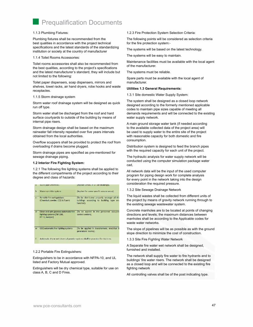
1.2.1 The following fi re lighting systems shall be applied tothe different compartments of the project according to theirdegree and class of hazards:
1.2.2 Portable Fire Extinguishers:
Extinguishers to be in accordance with NFPA-10, and ULlisted and Factory Mutual approved.
Extinguishers will be dry chemical type, suitable for use onclass A, B, C and D Fires.
1.2.3 Fire Protection System Selection Criteria:
The following points will be considered as selection criteriafor the fi re protection system:-
The systems will be based on the latest technology.
The systems will be easy to maintain.
Maintenance facilities must be available with the local agentof the manufacturer.
The systems must be reliable.
Spare parts must be available with the local agent ofmanufacturer.
Utilities 1.3 General Requirements:
1.3.1 Site domestic Water Supply System:
The system shall be designed as a closed loop networkdesigned according to the formerly mentioned applicablecodes to maintain pipe sizes capable of meeting alldemands requirements and will be connected to the existingwater supply network.
A main ground storage water tank (if needed accordingto the available collected data of the project area) willbe used to supply water to the entire site of the projectwith reasonable capacity for both domestic and fi reconsumption.
Distribution system is designed to feed the branch pipeswith the required capacity for each unit of the project.
The hydraulic analysis for water supply network will beconducted using the computer simulation package watercad,
All network data will be the input of the used computerprogram for piping design work for complete analysisfor every point in the network taking into the designconsideration the required pressure.
1.3.2 Site Sewage Drainage Network
The liquid wastes shall be collected from different units ofthe project by means of gravity network running through tothe existing sewage wastewater system.
Concrete manholes are to be located at points of changingdirections and levels; the maximum distances betweenmanholes shall be according to the Applicable codes forwaste water networks.
The slope of pipelines will be as possible as with the groundslope direction to minimize the cost of construction.
1.3.3 Site Fire Fighting Water Network
A Separate fi re water wet network shall be designed,furnished and installed.
The network shall supply fi re water to fi re hydrants and tobuildings’ fi re water risers. The network shall be designedas a closed loop and will be connected to the existing fi refi ghting network
All controlling valves shall be of the post indicating type.

www.pce-consultants.com
Prequalifi cation Documents
48
Notes:
Mobile dry chemical powder, fi re extinguishers shall beprovided adequately nearby the electricity rooms and fueltanks ... etc., in addition to the automatic special systemsthat mentioned here above.
Fire Brigade Siamese connections shall be provided ataccessible locations to serve the buildings.
2. Capabilities and software:
Our capability to accomplish the assigned job comes fromour long experience in dealing with similar large projects;our practice is to employ the associated latest softwaretechnology on performing the system’s design works withkeeping a well reactive engineering sense and a goodunderstanding of the currency of engineering procedures.The applied design software programs in our departmentare as follows:
Water cad for pressurized water networks.
Cyber Net for pressurized fi refi ghting and irrigationnetworks.
Sewer Cad for gravity pipelines.
AutoCAD 2011 for graphical works.
Word 2007 for reports production.
Excel 2007 for reports production.
Our department management and organization system willhelp to ensure the perfect design procedure and the preciseauditing system. A highly qualifi ed and equipped surveyingteam will undertake the site data collection perfectly incoordination with the technically specialized persons.

www.pce-consultants.com
Prequalifi cation Documents
49
- Infrastructure Methodology-Introduction
-Understanding the Scope of Consultancy Services -Applicable Design Codes
-Methodology
Infrastructure Methodology

www.pce-consultants.com
Prequalifi cation Documents
50
INFRA. METHODOLOGY
1. Introduction
The scope of this technical report is to outline the differentwater supply, sewerage, storm drainage fi re fi ghtingtasks that are anticipated to be included in the project.A complete detailed design including, detailed designdrawings, technical data, calculation sheets, technicalspecifi cations & B.O.Q. shall be prepared in compliancewith the requirements of these documents. The applicablecodes included in these documents are governing all designprocesses & materials selection. The design works shall beestablished taking into consideration the special nature andcharacteristics of the project. Electromechanical works thatare related to sanitary and fi re fi ghting jobs are also includedin the report.
2. Understanding the Scope of Consultancy Services
Works covered under these documents shall include but notlimited to the following:
Plumbing, sanitary fi xtures, storms drainage and fi re fi ghtingworks & systems for the various buildings that are includedin the project.
Water supply system.
Sewage drainage system.
Storm drainage system.
Fire fi ghting water system.
3. Applicable Design Codes
All the included design works shall be undertaken incompliance with the applicable specialized design codesand standards, international codes may also be applied afterbeing approved by the owner.
4. Methodology
This chapter describes the consultants proposed approachand methodology indicating the basic philosophy, theprincipal methods and procedures which shall be used inthe project. It’s presented in a brief form to facilitate readingand following up. The suggested approach and methodologyis analysis of project objectives and benefi ciaries. Thefollowing is our suggested methodology
4.1 Data Collection and 4.1 Updating Data Base
This task is perhaps the most important since its outputs willset the bases for the best of the project. It will infl uence thetechnology choices and the project sizes and magnitude.This task is proposed to fl ow on three consecutive steps,these are data collection, then review and analysis andfi nally data updating.
A. Data collection
All available data from client and all possible sources willbe collected. The basic data is that received from the clientupon awarding signing of the contract these data shouldinclude:
All available maps and data base
Water supply system included the site.
Sewer system included the site.
Water source.
www.pce-consultants.com
Prequalifi cation Documents
51
B. Data review and assessment
This activity is an offered based function during which alldata collected under activity will be the validated, analyzedand assessed for fulfi lling the feasibility study input dataand the design needs any gaps of data that will hinder theproducers of quality study and design will be identifi ed.The proposed methodology as presented later will thenbe adapted. Some of the data will be updated by projectfi eld team while some others data like utilities maps andconditions for example, if beyond such capabilities henceit will be subcontracted whether by the consultant or by theowner based on its type and nature.
Design will be prepared including standards, choice ofmaterial, design criteria and parameters design data forrelevant components, and all required design drawings. Theconsultant will use the modern computerized programs Toensure the quality of the design the team members will usea design checklist. The checklists indicate the general typesof tasks performed during the different phases of the project.
As a policy of our company to ensure that the highest orderof technical competence is illustrated in each and everyproject our company perform and that recommendation toclient represent the best and most appropriate solutions totheir needs. The quality assurance program of the form, hasconsidered two main things fi rstly the need to satisfy clientrequirements by producing services which are fi t for purposewithin budget and on schedule, and secondly the need tosupply these service in the most effi cient and cost effectivemanner by introducing effective management system.
The quality assurance program includes the controlsto be exercise on those aspects of the function, whichhave an effect on quality to ensure conformance to clientrequirements. The system out limed not only refl ects thecurrent quality policies but also take into consideration. Therequirements of national and international standers andregulations related to QA, such as ANSI/ASME,NQA-1,BS570.1 and ISO9001. The detail engineering designdrawings will be prepared to complement or modify thosealready existing and will be suffi ciently detailed to enable billof quantities to be prepared and works to be executed.

www.pce-consultants.com
Prequalifi cation Documents
52

www.pce-consultants.com
Prequalifi cation Documents
53
- Landscape Methodology -Introduction
-Performance Stages
Landscape Methodology

www.pce-consultants.com
Prequalifi cation Documents
54
LANDSCAPE METHODOLOGY
1. Introduction
In respect of the client of project, “Design and SupervisionConsultancy Services for Ras Al Hamra Luxury Hotel “to study, design and supervise the construction accordingto the owner and employer’s objectives the Departmentof Urban and Landscape in PCE fi rm has been committedto implement the methodology and tasks according to thefollowing:-
The selected method to be adopted in the process of thedetailed design & landscape for the Project may be fardepends on the following rational process and supportedwith a comprehensive view and integrated works program.
This selected approach best suited for realizing theobjectives in the scope of work and not constrained to thosein this document in the light of proposed performed stages.
2. Performance Stages
Stage One: Landscape Concept design and DetailedDesign Development
Phase I: Data gathering, analysis, studies and evaluation
Phase II: Detailed plan Design development
Phase III: Landscape design preliminary Package.
Stage Two: Full Tenders Documents for the Project
Full Working drawing for detailed Plans.
Working drawing and tender documents for Landscapedesign.
Detailed Budget, Detailed Bill of Quantities andSpecifi cations
Final Project Report
Preparation of Tender Package
Stage One: Detailed plan development and landscapeConcept design:
Phase I: Data gathering, analysis, studies andevaluation
1.1 Review the validity and accuracy of all technicalinformation, check the rationality,
accessibility of the site, applicability of relevant cods, andexisting statutory regulations of concerning Ministries.
1.2 Date gathering: In this phase physical information,would be surveyed and collected at the micro and macroscale such as surrounding vicinal land uses, externalities,demographic users cultural and behavior, soil investigationreports, topographic feature, environment impact, microclimate considerations, availability of amount of irrigationwater and types (recycle, treated, pipe water…. etc.).
environment impact, micro climate considerations,availability of amount of irrigation water and types(recycle, treated, pipe water…. etc.). Required informationwill be obtained from such sources, concerning Ministriesand Authorities (Electricity, public water communicationsDefense, National Housing, Oil company …etc.), a realphotography, survey maps, site photographs, publishedinformation, site visit and reports.
Also an accurate information objectives, regulations anddevelopment polices will be collected and discussed withconcerning bodies in order to develop the detailed plan, andto achieve the design .
www.pce-consultants.com
Prequalifi cation Documents
55
I.3 Data process and the analysis of data assembled:
Identifi cation of key issues, constraints, opportunities andcorrelation of government Ministries and their policies andalso analysis of properties, potentialities, socio-economic,and physical constraints, surrounding building accessibility’s,social behaviors, building/ user identities…etc.
Phase II: Detailed plan Design development
Instrumental objectives and evaluation criteria in a lightof the above comprehensive surveys, interviews withresponsible bodies and the output past experiences aboutsuch projects.
Preparing the detailed plan will take in consideration thefollowing Items :
Follow the master plan guidelines
Respect of the existing master plan which showing thedistribution of the 4 types of buildings on the individual plots.
Building orientation and window placement shall bedesigned to allow for direct views to the open space areas,while maintaining a high degree of privacy.
Orientation and position of windows of main residentialrooms shall be at suffi cient distance from adjacent uses toreduce visual intrusion.
For the amenity area, the detailed plan will consider the RFPphases which include :
Concept design phase
Schematic Design phase
Detailed Design phase
Tender documents
And will consider also the following issues:
- The nature of different activities
- Parking areas
- Landscaping of the amenity area
General Notes :
The design will take in consideration the IT requirements,cost and value engineering.
The Detailed design shall be inclusive and not limited to thepreparation of detailed drawings, BOQ, Specifi cations andall other needed details.
Any authority approvals shall also obtained prior tofi nalization of the detailed documentations.
Phase III: Landscape design preliminary Package
1 - Conceptual design stage
2 - Schematic/detailed design stage
Conceptual design stage:
1.1 Scope of Work:
The landscape consultant services will be a part of acomprehensive conceptual design
report of the project and will be dealt with required
professional services by proposing number of alternativedesigns, adopting possible applied standards of allapproved norms of soft/hard landscape. Furthermore,great attention will be paid by Dept. to formulate useful andcrucial design considerations and recommendation in orderto improve the task output. Also the report of landscapeservices will identify number of proposals for the selecteddesign philosophy, formulate convenient design policies andadopted criteria which associated with Road Departmentthat would be employed for the road landscape work.
Main design policies would emphasize to minimizemaintenance capital running cost, efforts and irrigationquantities but on the other hand conserve the possiblebeautifi cation residential feature of the case studyneighbourhood and network roads. Also the selectedlandscape items should maximize the natural shaded areasalong road pass ways to protect pedestrian from sunrays.
In addition the conceptual design report will attempt toexpect in digital fi gures the externalities impact on areaas whole in order to determine relative advantages /disadvantages of each proposed alternative. A conventionalprocedure of evaluation methodology such as cost / benefi tanalysis or balance sheet may be adopted to optimize thedecision of selecting best proposal.
According to the RFP some other issues should be taken inconsideration like:
The landscape design shall be performed within theresidential and amenities plots, and for the open publicareas and the parking areas surrounding the amenitiesbuildings.
The landscape design within the property premises shallallow for protection from excessive summer sun.
The design should provide a variety of recreationalopportunities and facilities (including lighting whereappropriate) that ensure high levels of activity for extendedperiods, and should include out-door furniture.
Select plant material that is suitable for the climate.
Select native plant material where appropriate and avoidusing excessive exotic plant species.
Avoid high maintenance plants and topiary.
The design should balance capital costs with ongoingmaintenance and operational costs.
Provide rock gardens and xeriscaping as much as possibleto minimize maintenance.
Minimize grass turf areas where possible, in order to reducewater consumption.
Ensure integration with storm water management landscapefeatures.
Prepare all technical Documents required for Permits andshall provide all technical support to obtain the ConstructionPermit.
1.2 Sources and capability of conceptual design:
Department Previous experiences in Saudi and othercountries in similar projects.

www.pce-consultants.com
Prequalifi cation Documents
56
Availability of adequate expert manpower.
Computer aide (soft program such as AutoCAD, GIS .. etc.)
Maps of walkover survey particularly for utility location andcoordination.
1.3 Technical Approach for Conceptual Design:
That will include Formulation of the design criteria forlandscape for roads, Safe pedestrian movement around theentire site, Construction of the proposed design for :
Hardscape design and material
Softscape design and material
According to the RFP the consultant is requested to preparethe documentation for all concept, schematic, detailed andtender landscape package for all public and private openspaces.
The major elements required for the successful study of thelandscape design include but not limited to the following:
Consideration of site and environmental constrains
Hardscape elements
Fences, Screen walls and retaining walls
Trees, shrubs, grass, lawn and fl owers
Ground cover
Landscape Furniture
Land forms
Paving, foot path, pavilion, tents … etc.
Open space furniture.
Calculations (quantities) and specifi cations.
According to the above we shall emphasize on thefollowing:
Hardscape design (Including Furniture items):
Applying the new boundaries of proposed carriage way andits concrete curbstones.
Provide retaining walls if needed.
Provide paved pathway perimeter to all site buildings.
Tidy up and upgrading the network of the existing mainpedestrian routes.
Provide the site with steps where it is necessary settingpergola, water drink machine, two rest bench hidden lights,waste pains, … etc.
Softscape design:
Study the shape and location of areas to be cultivated.
Upper and bottom soil analysis and relevant seeds to beused in site and improving soil quality for irrigation andcultivation.
Organic and chemical fertilizer.
Determine the most convenient shrubs for site andresidential functions and also for the amenity zone.
Applying the selected way of cultivating the grass, palmtrees, shrubs and requirements of irrigation water.
Planting process :
Clean the site.
The way of transporting the plants and best way to bestored in site to prevent the dray effects and defi ned theamount of original soil.
Prepare the ground of planting and to select the mostconvenient kind of palm trees and shrubs and soiltreatment.
The way of fi xing the palm trees and supporting ways inpits.
Determine the most suitable for time plantation for eachexported kind of plant.
Job of planting maintenance and supervising for one year.
Exchanging process of plants growing up during theinfancy stage of plantation.
Applied Standards of Landscape Design:
Saudi Codes, Standards and Guidelines
Tropical Encyclopedia of Agricultural Plants “LandscapePlants”
American standard for Nursery Stock (ANSI Z601) 1973edition American Association of Nurserymen.
British Standards
Submission of data report and conceptual drawings:
The following shall be submitted:
Concept Design Report, showing the following:
Objectives of landscape design.
Principal of philosophy design.
Two colored alternative concept drawings for the projectsite plan shown the information and idea for hard/softscapedesign and furniture Items.
Conceptual design of site levelling for proposed landscapessetting.
Sketches for hard and soft scape proposal designs ofpedestrian nodes, pattern of fl oor tiles, road furniture,squares or round about landmarks, and palm trees andtrees pits… etc.
Conceptual design drawings of proposed vegetationdistribution and selected types and specifi cation in aconvenient scale.
According to the RFP the Landscape Concept DesignDeliverables would be the following:
a - Report:
A Report describing the Landscape design intent and theproject identity.
Budget estimate for the external works.

www.pce-consultants.com
Prequalifi cation Documents
57
b. Plans:
Layout plans at appropriate scale to refl ect the overalldesign intent
Layout plans of detailed areas at appropriate scalerepresenting the gateways, markers, furniture, open spacetreatments
Graphic cross sections and illustrative sketches of detailedareas.
Dimension growth for each Tree in order to calculate thespace between each tree.
c. Presentation Boards:
A1 Scale presentation boards indicating the sample picturesand / or color drawings for material and components withillustrative sketches and images.
Sample material and / or picture boards indicating the openspace furniture style and use for each individual area.
Sample material and / or color drawings indicating the scaleand design intent.
d. Plant Selection:
Preliminary listing of plant and Species required with theircommon and botanical names.
Evaluation methodology (balance sheet):
Adopted sets of criteria whether for design of proposals ornumerical evaluation methods and scores.
Results of evaluations of each proposal (relative advantages& disadvantages).
All sets of consultant’s considerations, importantrecommendations and theoretical suggestions.
Brief of expected externalities impact (positive & negative).
Proposal scenarios for implementation of proposedlandscaping items.
Cost wise of project landscape work.
Schematic/Detailed Design Stage:
On approval of the conceptual design, the landscape Dept.shall prepare a preliminary design, and shall submit thefollowing:
1. Site Development Plans and colored general layout planof the proposed hard/soft landscape work shown full details(but without dimensions) of design:
Hardscape elements:
Pedestrian pass way pattern of fl oor interlock, outdoorlighting column fi xed in green areas, seats design, pergolas,waste pain locations, trees and palm tree pits, retainingwalls if will necessary, steps, signs, fountains, symbolicelements, and board for advertisement, fences and naturalrocks.
Softscape elements:
Trees, palm trees, shrubs, fl owers grass areas, cactus pits,…. etc.
2. Preliminary site leveling and earth moving package ifnecessary for landscaping work. The
basic geometry of all horizontal and vertical alignmentcontrol lines necessary to defi ne the work will be applied.
3. Typical cross sections, showing carriage ways inaccordance with proposed hard/soft landscape on bothsides of roads. Also vegetation barrier in middle of the roadif necessary will be shown to prevent night glare of car lightin both directions of road if it will be possible.
4. Colour perspective drawings for the way and degree ofthe night illumination of any road landmark.
5. Sewerage layout plans in convenient scale (1:100) –(1:200) of pedestrian pass ways shown direction and slopesof water sewerage, gutter fl ow lines and tree pits locations.
6. Setting out any required details for this stage to explainthe design procedure.
7. Submission the part of a preliminary design drawings forlandscape work to management Engineer.
According to the TOR the Landscape schematic/DetailedDesign Deliverables would be the following:
This phase shall commence upon approval of theLandscape concept Design documents by the Employer andafter obtaining specifi c written approval to proceed.
Sites development plans
Layout plans including, footpaths, pools, planting, walls,water features and other entry features
Detailed sections and elevations to complement the layoutplans
Typical details for all fi nishes
Grading plans showing all mounds, berms, … etc. anddemonstrating considerations taken for surface water run-off
Soft landscape; Palm, Trees, Shrubs and groundcovers.
Feature planting details
A survival details for each plant.
Preliminary listing and nos. of plant and Species requiredwith their common and botanical names.
Sources and address of suppliers of all types of plants andspecies, where these are to be procured from abroad.
Suitable planting and replanting seasons and recommendedmethods.
Hard Landscape: Paving materials, walls and cladding, sitefurnishings
External fences, gates, railings, parapets, pavilions,structures and screen walls.
Open Space furniture and contained planters.
Detailed design for the simple water features
Landscape lighting for landscape items
Detailed design for any structural elements such asretaining walls and plots fences.

www.pce-consultants.com
Prequalifi cation Documents
58
Provide a detailed budget based on the detailed BOQ anddetailed Specifi cations for the project.
Stage Two: Full Tenders Documents for the project
Working drawing and tender documents for detailed Plan.
Working drawing and tender documents for Landscapedesign.
Preparing of Bill of Quantities and Specifi cations.
Final Project Report
In this stage our department will emphasize on thefollowing:
1. Working drawing and tender documents for detailed Plan
At this stage emphasize to prepare all the details and dataof the project, which helps the site engineer to complete thetask of preparing the site and building reticulation facilitiesand infrastructure under the surface without any obstacles.
2. Landscape Details Design Stage – Tender documents :
a - Hardscape Design Tender documents:
Dimension, coordinates and levels of the hardscapeelements and locations.
The plan, section and elevation drawings of the proposedmonumental objectives.
Any selected type of the soil slope protection (retaining wall)if it would be necessary as well as stairs and steps.
The design and distribution of garden electrical indirectlighting.
Seats, shades, Telephone cabinet, etc.. all street furniturein details.
Pedestrian pass way tiles and pattern, the sub-basecourses and layers and the way of installation.
Design of the proposed water foundations at mainentrances (if needed).
Advertising boards, fl ag carriers, etc.
b - SoftScape design – Tender documents:
Dimension, coordinates and levels of the proposedsoftscape types and locations of trees pits be determinedalso the proposed irrigation values and system would bedefi ned on the appropriate details.
The drawings of selected kinds of plan trees, shrubs,ground covered plants, and pass pan grass and themethod of fi xation, irrigation, and soil treatment, washingand fertilization also would be mentioned and displayed indetails.
All details of the following plantation process would bementioned or in drawings forms to explain the method ofimplementation :
Preparing the planting areas: cleaning the site, shaping thesite, existing trees, shrubs, grass, etc.
Soil fertilization and replacement: materials, seeds, materialof soil property improvement, vermicide and herbicide.
Plant samples and material tests.
Preparing the top and bottom soil.
Maintenance instructions of selected plants andreplacements specifi cations.
Time for plant transportation, fi eld inspections of plants,methods for storing out/in door, time of planting.
Ways of measurements.
C - The following would be submitted on fi nal stage:
Master Layout: Scale 1/500, For all the design roadslandscape hardscape, softscape and Furniture.
Dimensions and coordinates drawings: Scale 1/200 – 1 /250, Showing the dimension of the Roads, Medians, thepattern of the sidewalks, Kerbs, Squares, The coordinatesof the Radius and all the softscape curves.
Hardscape Drawings: Scale 1/200 – 1 / 250 Showing thepattern of the walkway, the medians the levels for all thewalkways and side walk and for all the Furniture in thelayout.
Softscape drawings: Scale 1/200 – 1 / 250 Showing thedesign of the Gardens, the trees, palms, shrubs, grass. Etc.and their kind and their coordinates in the site.
Hard and softscape details: Scale 1/100 – 1 / 50 – 1 / 25..Etc.
3. Bill of Quantities and Specifi cations:
Preparation of the tender documents, the bill of quantities,specifi cations, implementation schedule, and sitemanagement would provide in details in best manner.
A detailed B.O.Q shall be produced and issued in A4 sizesheets in both hard and editable soft copy format.
4. Final Project Report:
The report for present stage shall be to A4 size inportrait format. The sketch stage report shall be bound inremovable plastic spirals. The text for title page shall bemutually agreed to between client and PCE before fi nalprinting.
All submission report and its drawings shall also besubmitted in an approved electronic format on CDs aswell as hard copies as required. All text documents shallbe submitted on Word format. All report’s drawings shallbe prepared in both AutoCAD map and revit (if needed)format using an approved layering system. There shall beon separate drawing fi le for each hard copy of the modularworking/presentation map. Profi le of electronic workingformat shall be as approved by client representative.
Deliverables for the whole project (drawings –reports) willcomply according to the TOR, Schedule – Deliverables.
Control Quality Insurance and feasibility of output services:
The Urban Department shall ensure that the consultantwork and services will be carried out in
accordance with two following provisions and control:
1- Quality of work.

www.pce-consultants.com
Prequalifi cation Documents
59
2- Compatible submission format.
1- Quality of Work:
Product of the project should be at the highest standards ofworkmanship and used materials, as scheduled and withinbudget and in accordance with specifi cations and drawings… etc. Documents.
The product of the project should be met Client’s ambitionand requirements and also the norms and to be inaccordance with environment.
The product of the project should be in accordance withchild safety and accessibility for elderly and disabled, whereapplicable/required.
2- Submission Format:
All drawings and sketches to be at a suitable scale todisplay the required information clearly.
Drawings’ size shall not be larger than A1 and shall besuitable for reduction to size A3 without losing information.
Submit electronic copies of all drawings and reports to theclient.
Text fi les shall be fully compatible with MS word, whileelectronic copies of drawings and plans shall be fullycompatible with AutoCAD or Revit where applicable.
All photographs and pictures shall be submitted inacceptable format and in high resolution.
Model space.

www.pce-consultants.com
Prequalifi cation Documents
60

www.pce-consultants.com
Prequalifi cation Documents
61
Precedents and Work Experience
- Precedents and Work ExperienceHospitals
-Military Hospital -Riyadh Hospital -Wady Elnile Hospital -Hael Hospital -Marina Medical Center- Marina -AlAbasia-Hospital -Najaf Hospital -Samawa Hospital -El Safa Hospital -Neuro Spine Hospital at 6Th Of October -Doctor Omar Kotb Lab
Pharmaceutical Industries -Marcyrl Factory -L’OREAL Cosmetic plant -Delta Pharma Factory

www.pce-consultants.com
Prequalifi cation Documents
62
-LIPTIS Factory for Pharmaceutical
Industrial -Taghleef Factory-6th October -Argo Factory- 6th October -Fine Factory- 6th October -Dabur Factory-10th of Ramadan
Infrastructure -King Khaled University Campus in Bisha -King Khaled University Campus in Abha -Misr Insurance Club-Mokattam -National Housing Project- 6th October-National Housing Project-Borg-El Arab -National Housing Project-Sohag -Sharming Inn Villas- Sharm El Shikh -Lhacienda-Ras Sedr -Gaca Lands Usage Study And Building Design
Commercial and Residential -National Bank of Egypt -Fifth District -Bank Faisal-Ismailia Branch -Landmark -Fifth District -ABHA Residential and Administrative Building -Gnena-Administrative and commercial building-Phase II -Azmeel’s Offi ce Building -Jedda -Riyadh Public Transport Control Center -Najeed Offi ces Building -Wady Elnile Admin Building -Azmeel’s Offi ce Building -Jedda-Hurghada City Center & Mixed Use Building-Hurgada -National Control Center Building -Grand Egyptian Museum- 6th October

www.pce-consultants.com
Prequalifi cation Documents
63
Hospitals
-Military Hospital -Riyadh Hospital -Wady Elnile Hospital -Hael Hospital -Marina Medical Center- Marina -AlAbasia-Hospital -Samawa Hospital -El Safa Hospital -Neuro Spine Hospital at 6Th Of October -Doctor Omar Kotb Lab

www.pce-consultants.com
Prequalifi cation Documents
64

www.pce-consultants.com
Prequalifi cation Documents
65
Misr University Hospital
Description and featuresMisr University Hospital Extension Building
It is a hospital building consist of basement, ground
and fi ve fl oors, each is 250m² built up area
Client : Misr University
Location: 6th October City, Egypt
Scope : Electro- Mechanical Design & Shop Drawings
Status : Completed

www.pce-consultants.com
Prequalifi cation Documents
66
Military Hospital
Description and featuresThe project consists of 400 bed, with a total area of 15,000meter square , 5 storey facility is a healthcare landmarkand celebration of life . The design optimizes the day today hospital workfl ow and operations , while enhancingpatient experience .
Built up area : 15000m²
Client : Military Hospital
Location: Saudi Arabia
Scope : Complete engineering design forArchitectural, Medical Planning, Medical Equipment,Structure, Infrastructure, Roads, Water treatment, andElectromechanical works
(Electrical, light current, HVAC, fi refi ghting , plumbing andmedical Gases works).

www.pce-consultants.com
Prequalifi cation Documents
67
Riyad Hospital
Description and featuresThe project consists of 400 bed, with a total area of 23,000meter square , 6 storey facility is a healthcare landmarkand celebration of life . The design optimizes the day today hospital workfl ow and operations , while enhancingpatient experience.
The 400 bed hospital features medical and surgicalservices , In-patient and Outpatient surgical
suites ,an Emergency department and ICU .
Built up area : 23000m²
Client : RIYADH HOSPITAL
Location: Jeddah, Saudi Arabia
Scope : Complete engineering design forArchitectural, Medical Planning, Medical Equipment,Structure, Infrastructure, Roads, Water treatment, andElectromechanical works
(Electrical, light current, HVAC, fi refi ghting , plumbing andmedical Gases works).

www.pce-consultants.com
Prequalifi cation Documents
68
Description and featuresIt is a hospital in Kobri El-Kobba consists of seven fl oorseach fl oor area 1200m².
Wady Elnile Hospital
Client : Wady El-Nile Company
Location: Kobri El-Kobba , Cairo, Egypt
Scope : Complete Plumbing, and Steam System Shop
Drawings
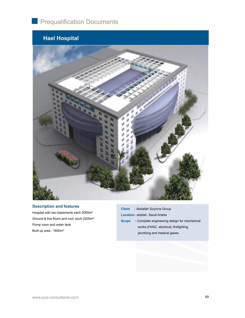
www.pce-consultants.com
Prequalifi cation Documents
69
Hael Hospital
Description and featuresHospital with two basements each 2000m²
Ground & fi ve fl oors and roof, each 2200m²
Pump room and water tank
Built up area : 1600m²
Client : Abdallah Soyinna Group
Location: Jeddah, Saudi Arabia
Scope : Complete engineering design for mechanical
works (HVAC, electrical, fi refi ghting,
plumbing and medical gases

www.pce-consultants.com
Prequalifi cation Documents
70
Description and featuresMarina Medical Center, it is a new medical center in marina4 in north cost, consists of :
Basement fl oor with built up area : 400m2
Ground Floor : 2800m²
First Floor: 2900m²
Roof Floor: 2800m²
Built up area: 8900m²
Marina Medical Center
Client : Dr. Mohamed Talaat
Location: Marina - Egypt
Scope : Complete HVAC, electrical, fi refi ghting,
Plumbing and infrastructure design.
Site supervision

www.pce-consultants.com
Prequalifi cation Documents
71
Al-Abasia Hospital
Description and featuresThe latest hospital for police academy, with 550 beds.
This hospital is ranked as one of the largest hospitals inEgypt.
Consists of eleven fl oors, from second basement to theroof each fl oor with built up area 5200m², and anotherancillary building as boiler, pump room, guard rooms.
Built up area : 62000m²
Client : Police Academy
Location: Abasia - Egypt
Scope : Complete engineering design for (HVAC,,
Mechanical gases, compressed air and
electrical systems)

www.pce-consultants.com
Prequalifi cation Documents
72
Najaf Hospital
Description and featuresOne medical edifi ce in Najaf area – Iraq, contain 400 beds.
The project consists of:
1.Main building have ground fl oor, fi rst fl oor, second fl oor,third fl oor and roof
Total build up area 120000m²
2.Staff building have ground fl oor, fi rst fl oor, second fl oor,third fl oor and terrace
Total built area 5100m²
3. Other utility buildings (lockers building, pump room, andguard house)
Built up area : 135000m²
Client : Ministry of Health
Location: Najaf - Iraq
Scope : Complete shop drawing for electro-
Mechanical works (HVAC, fi refi ghting ,
Plumbing, electrical, light current and
Infrastructure networks)
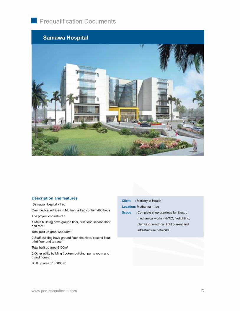
www.pce-consultants.com
Prequalifi cation Documents
73
Description and features Samawa Hospital - Iraq
One medical edifi ces in Muthanna Iraq contain 400 beds
The project consists of :
1.Main building have ground fl oor, fi rst fl oor, second fl oorand roof
Total built up area 120000m²
2.Staff building have ground fl oor, fi rst fl oor, second fl oor,third fl oor and terrace
Total built up area 5100m²
3.Other utility building (lockers building, pump room andguard house)
Built up area : 135000m²
Samawa Hospital
Client : Ministry of Health
Location: Muthanna - Iraq
Scope : Complete shop drawings for Electro
mechanical works (HVAC, fi refi ghting,
plumbing, electrical, light current and
infrastructure networks)
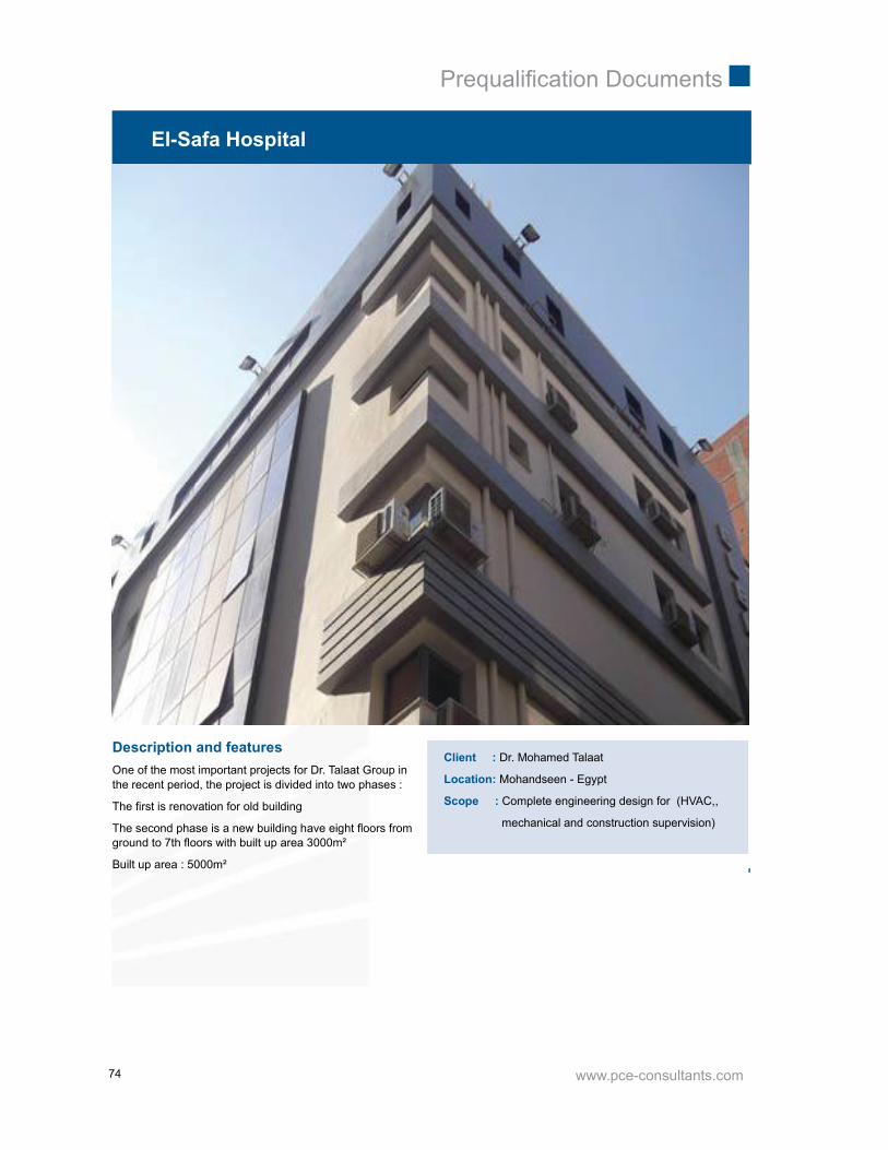
www.pce-consultants.com
Prequalifi cation Documents
74
Description and featuresOne of the most important projects for Dr. Talaat Group inthe recent period, the project is divided into two phases :
The fi rst is renovation for old building
The second phase is a new building have eight fl oors fromground to 7th fl oors with built up area 3000m²
Built up area : 5000m²
El-Safa Hospital
Client : Dr. Mohamed Talaat
Location: Mohandseen - Egypt
Scope : Complete engineering design for (HVAC,,
mechanical and construction supervision)

www.pce-consultants.com
Prequalifi cation Documents
75
Description and featuresOne of the most important projects for Dr. Youssry Groupin the recent period, the project is consists of :
The design review stage, and the site supervision.
Built up area : 3000m²
Neuro Spine Hospital
Client : Neuro Spine Hospital
Location: 6Th Of October - Egypt
Scope :Complete engineering design review for HVAC,and construction supervision)
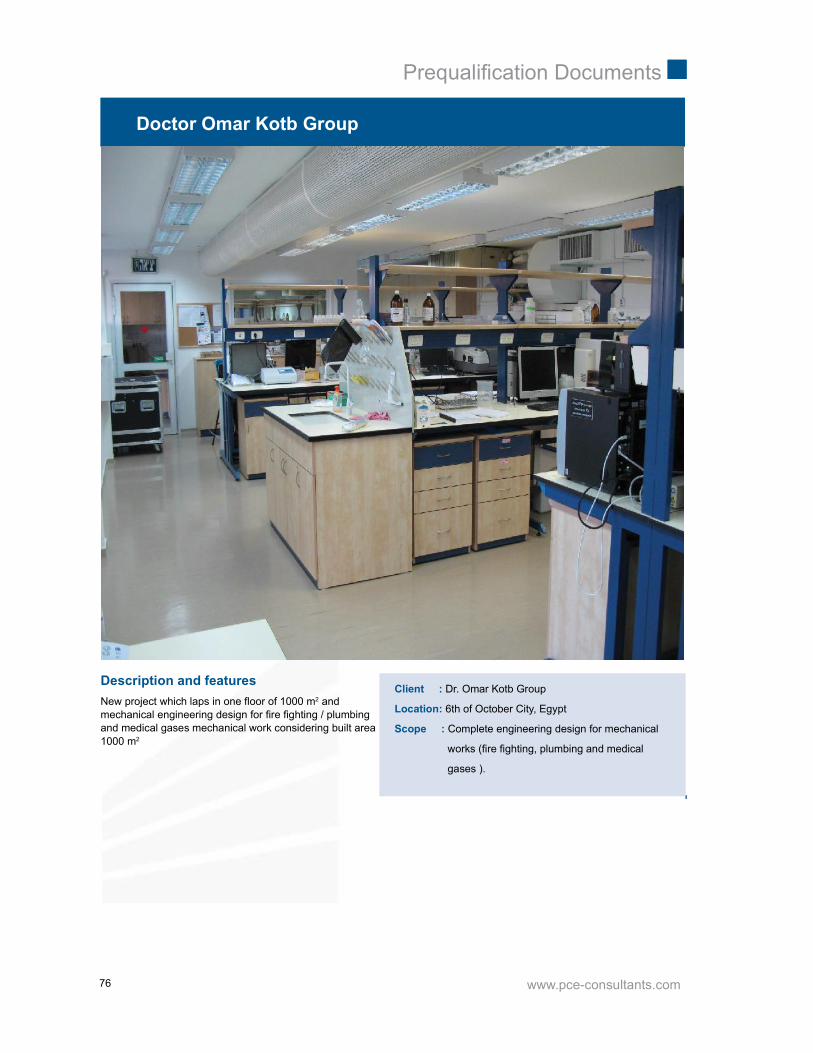
www.pce-consultants.com
Prequalifi cation Documents
76
Doctor Omar Kotb Group
Description and featuresNew project which laps in one fl oor of 1000 m2 andmechanical engineering design for fi re fi ghting / plumbingand medical gases mechanical work considering built area1000 m2
Client : Dr. Omar Kotb Group
Location: 6th of October City, Egypt
Scope : Complete engineering design for mechanical
works (fi re fi ghting, plumbing and medical
gases ).

www.pce-consultants.com
Prequalifi cation Documents
77
Pharmaceutical Industries
-Marcyrl Factory -L’OREAL Cosmetic plant -Delta Pharma Factory -LIPTIS Factory for Pharmaceutical

www.pce-consultants.com
Prequalifi cation Documents
78

www.pce-consultants.com
Prequalifi cation Documents
79
Description and featuresThe project is consisting of:
1 -Production building which contain, Harmon Predictionarea, packing area & manufacturing area, storage areawith total built up area of 5000 m²
2- Labs area with built up 1500 m²
3- Utilities building with built up 500 m²
Built up area 10000 m²
Marcyrl Pharmaceutical Industries
Client : Marcyrl Pharmaceutical Industries
Location: El-Obour City, Egypt
Scope : Complete engineering design forArchitectural, Structure, Infrastructure, Roads, Watertreatment, and Electromechanical works
(Electrical, light current, HVAC, fi refi ghting, plumbing andmedical Gases works).

www.pce-consultants.com
Prequalifi cation Documents
80
Description and featuresThe project is consisting of:
1- Production building which contain, packing area builtup 2500m² & manufacturing area with built up 1900m²&control building with built up 2700m²and storage area withbuilt up 6500m²
2- Technical building with built up 1000m²
3- Other utility building (lockers building &pump room andguard house)
Built up area 15000m²
L’OREAL Cosmetic plant
Client : L’OREAL Cosmetics Industry
Location: 10th of Ramadan City , Egypt
Scope : Complete engineering design & complete
shop drawing for mechanical works
(Electrical, light current, HVAC, fi refi ghting
, plumbing and infrastructure works).

www.pce-consultants.com
Prequalifi cation Documents
81
Description and featuresDelta Pharma Factory
The factory consists of two buildings production area andlaboratories.
Production area consists of two fl oors:
Ground fl oor contain solid production area and stores
Built up area 9500m² which contain offi ces, lockers andproduction area
Laboratories building consist of 4 fl oors each 500m²
Delta Pharma Factory
Client : Delta Pharmaceutical Company
Location: 10th of Ramadan City , Egypt
Scope : Complete Electromechanical design
(HVAC, fi refi ghting , plumbing, electrical and
infrastructure)

www.pce-consultants.com
Prequalifi cation Documents
82
LIPTIS Factory for Pharmaceutical
Description and featuresA factory consists of two fl oors
Ground with built up area 9500m², which containproduction area, laboratory and mechanical stores
First fl oor with built up area 1000m2, which containoffi ces, general store and lockers
Built up area : 10500m²
Client : LIPTIS Factory for Pharmaceutical
Location: 6th of October City, Egypt
Scope : Complete engineering design and complete
shop drawings for fi refi ghting works

www.pce-consultants.com
Prequalifi cation Documents
83
Industrial
-Taghleef Factory-6th October -Argo Factory- 6th October -Fine Factory- 6th October -Dabur Factory-10th of Ramadan

www.pce-consultants.com
Prequalifi cation Documents
84

www.pce-consultants.com
Prequalifi cation Documents
85
Description and featuresA Factory consists of two fl oors
Ground fl oor with built up area 9500m², which contain millroll rack laboratory, mechanical stores, electrical stores andboilers room
First fl oor with built up area 1000m² which contain offi cesand general store and lockers
Built up area : 10500m²
Taghleef Factory
Client : Taghleef Industries (Egypt Plant )
Location: 6th of October City, Egypt
Scope : Complete engineering design, complete shop
drawings for mechanical works (HVAC,
fi refi ghting and plumbing), and infrastructure
works
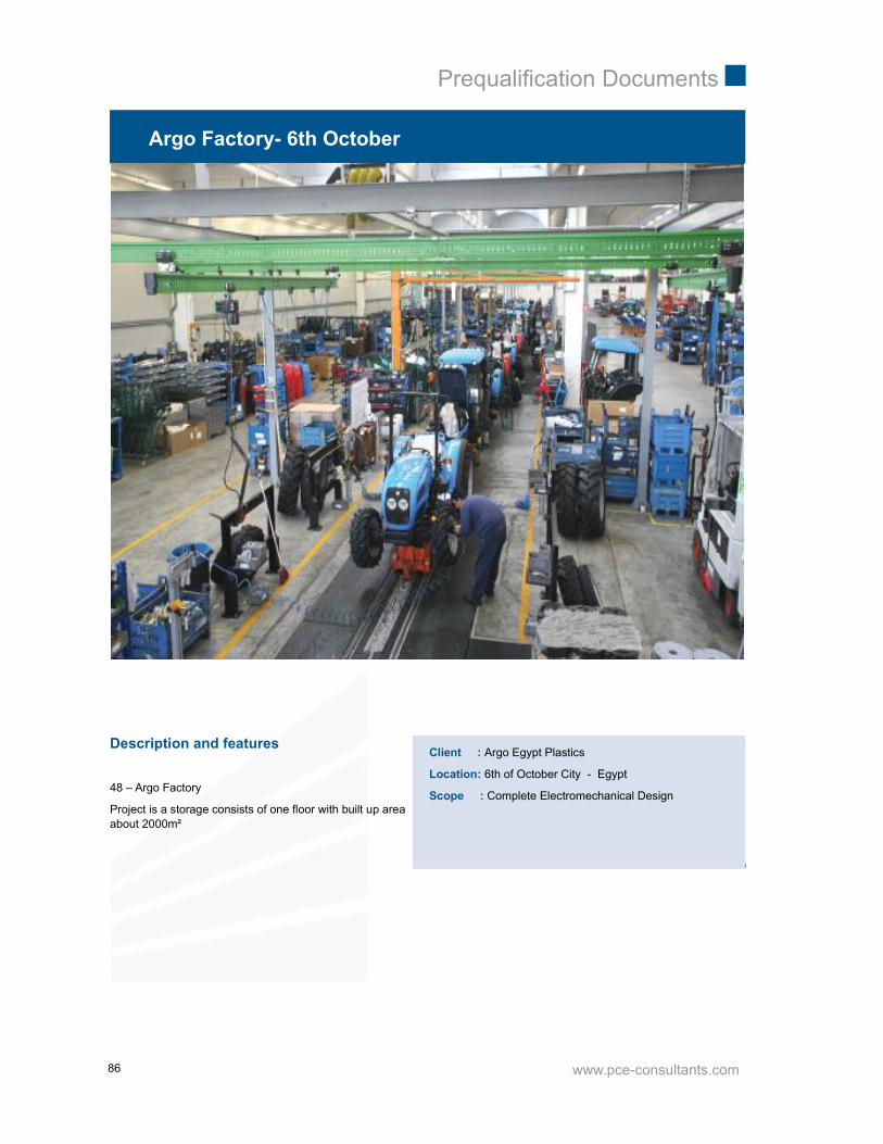
www.pce-consultants.com
Prequalifi cation Documents
86
Argo Factory- 6th October
Description and features
48 – Argo Factory
Project is a storage consists of one fl oor with built up areaabout 2000m²
Client : Argo Egypt Plastics
Location: 6th of October City - Egypt
Scope : Complete Electromechanical Design

www.pce-consultants.com
Prequalifi cation Documents
87
Fine Factory- 6th October
Description and featuresFine Factory - 6th of October City
Value: 2 million L.E.
Client : Fine Company
Location: 6th of October City , Egypt
Scope : Complete mechanical design including HVAC
and compressed air

www.pce-consultants.com
Prequalifi cation Documents
88
Dabur Factory-10th of Ramadan
Description and featuresDabur Factory
It is a new factory for dabur group for cosmetics in 10th ofRamadan city.
The project consists of main building contain storage areaand administrative area with 3 fl oors.
Built up area : 15000m²
Client : Dabur Group
Location: 10th of Ramadan City - Egypt
Scope : Complete fi refi ghting design, complete
Firefi ghting shop drawings and supervision of
Construction

www.pce-consultants.com
Prequalifi cation Documents
89
Infrastructure
-Dabur Factory-10th of Ramadan -King Khaled University Campus in Bisha -King Khaled University Campus in Abha -Misr Insurance Club-Mokattam-Egypt -National Housing Project- 6th October-National Housing Project-Borg-El Arab -National Housing Project-Sohag -Sharming Inn Villas- Sharm El Shikh -Lhacienda-Ras Sedr -Gaca Lands Usage Study and Building Design

www.pce-consultants.com
Prequalifi cation Documents
90
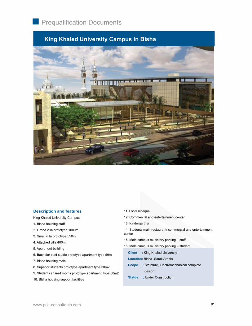
www.pce-consultants.com
Prequalifi cation Documents
91
King Khaled University Campus in Bisha
Description and featuresKing Khaled University Campus
1. Bisha housing staff
2. Grand villa prototype 1000m
3. Small villa prototype 550m
4. Attached villa 400m
5. Apartment building
6. Bachelor staff studio prototype apartment type 50m
7. Bisha housing male
8. Superior students prototype apartment type 30m2
9. Students shared rooms prototype apartment type 60m2
10. Bisha housing support facilities
Client : King Khaled University
Location: Bisha -Saudi Arabia
Scope : Structure, Electromechanical complete
design
Status : Under Construction
11. Local mosque
12. Commercial and entertainment center
13. Kindergartner
14. Students main restaurant/ commercial and entertainmentcenter
15. Male campus multistory parking – staff
16. Male campus multistory parking – student

www.pce-consultants.com
Prequalifi cation Documents
92
Description and featuresKing Khaled University Campus.
Project consists of two proto types buildings (KKu1,2)
KKU1 consists of 6 fl oors with built up area 26400m²
KKU2 consists of 6 fl oors with built up area 13100m²
King Khaled University Campus in Abha
Client : King Khaled University
Location: Abha – Saudi Arabia
Scope : Complete structure and electromechanical
design
Status : Under Construction

www.pce-consultants.com
Prequalifi cation Documents
93
Misr Insurance Club-Mokattam
Description and features Misr Insurance Club
It is a new extension in Mokattam, Misr Insurance Clubconsists of administrative building, new park area,swimming pool, foundations and stadium, with total built uparea 60000m²
Client : Misr Insurance Company
Location: Mokattam - Egypt
Scope : Complete electromechanical design for the
( electrical, light current, HVAc & fi refi ghting,plumbing and infrastructure)
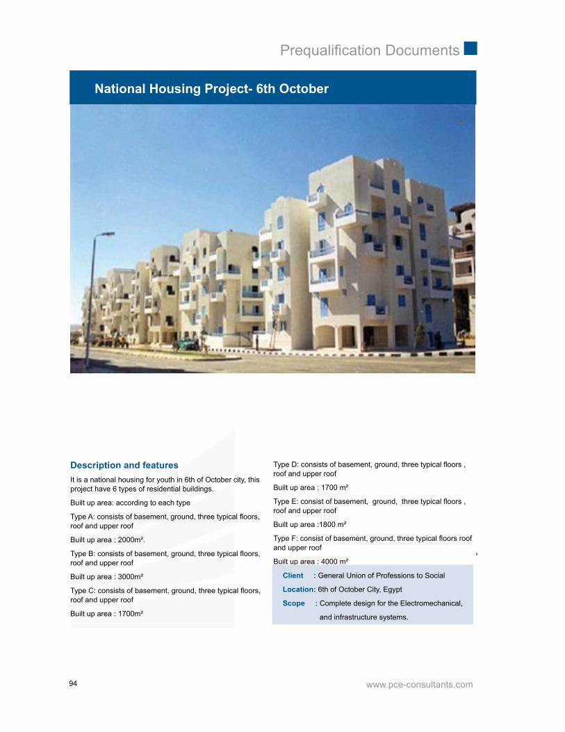
www.pce-consultants.com
Prequalifi cation Documents
94
National Housing Project- 6th October
Description and featuresIt is a national housing for youth in 6th of October city, thisproject have 6 types of residential buildings.
Built up area: according to each type
Type A: consists of basement, ground, three typical fl oors,roof and upper roof
Built up area : 2000m².
Type B: consists of basement, ground, three typical fl oors,roof and upper roof
Built up area : 3000m²
Type C: consists of basement, ground, three typical fl oors,roof and upper roof
Built up area : 1700m²
Type D: consists of basement, ground, three typical fl oors ,roof and upper roof
Built up area : 1700 m²
Type E: consist of basement, ground, three typical fl oors ,roof and upper roof
Built up area :1800 m²
Type F: consist of basement, ground, three typical fl oors roofand upper roof
Built up area : 4000 m²
Client : General Union of Professions to Social
Location: 6th of October City, Egypt
Scope : Complete design for the Electromechanical,
and infrastructure systems.

www.pce-consultants.com
Prequalifi cation Documents
95
Description and featuresIt is a national housing for youth in Borg El-Arab city, thisproject have 4 types of residential buildings.
Built up area: according to each type
Type A: consists of basement, ground, three typical fl oors,roof and upper roof
Built up area : 2000m².
Type B: consists of basement, ground, three typical fl oors,roof and upper roof
Built up area : 3000m²
Type C: consists of basement, ground, three typical fl oors,roof and upper roof
Built up area : 1700m²
National Housing Project-Borg-El Arab
Client : General Union of Professions to Social
Location: Borg El-Arab, Egypt
Scope : Complete design for the Electromechanical,
and infrastructure systems.
Type D: consists of basement, ground, three typical fl oors,roof and upper roof
Built up area : 1700 m²

www.pce-consultants.com
Prequalifi cation Documents
96
National Housing Project-Sohag
Description and featuresIt is a national housing for youth in Sohag city, this projecthave 4 types of residential buildings.
Built up area: according to each type
Type A: consists of basement, ground, three typical fl oors,roof and upper roof
Built up area : 2000m².
Type B: consists of basement, ground, three typical fl oors,roof and upper roof
Built up area : 3000m²
Type C: consists of basement, ground, three typical fl oors,roof and upper roof
Built up area : 1700m²
Client : General Union of professions to social
Location: Sohag City, Egypt
Scope : Complete design for the Electromechanical,
and infrastructure systems.
Type E: consists of basement, ground, three typical fl oors ,roof and upper roof
Built up area : 1800 m²

www.pce-consultants.com
Prequalifi cation Documents
97
Description and features39 Sharming Inn Villas, consists of group of four types
of villas, parking and hotel with total area about 160000m²
Sharming Inn Villas- Sharm El Shikh
Client : Sharming Inn Group
Location: Sharm El-Sheikh, Egypt
Scope : Complete Electro mechanical design for
(HVAC, fi refi ghting , plumbing, light current,
electrical and infrastructure design )

www.pce-consultants.com
Prequalifi cation Documents
98
Lhacianda
Description and featuresLa Hacienda is located in Ras Sudr in South Sinai on theeast coast of the Suez Gulf.
It is 210 km away from Cairo near the mid-point betweenCairo and Sharm El-Sheikh.
Our scope is complete infrastructure and MEP design forphase two, and design review for phase one.
Built up area: 470.000 m2
Client : Bahrawi Invsetment Co.
Location: Ras Sidr, Egypt
Scope : Complete design for the Electromechanical,
and infrastructure systems.
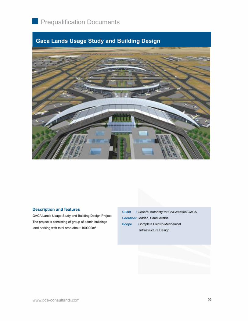
www.pce-consultants.com
Prequalifi cation Documents
99
Description and featuresGACA Lands Usage Study and Building Design Project
The project is consisting of group of admin buildings
and parking with total area about 160000m²
Gaca Lands Usage Study and Building Design
Client : General Authority for Civil Aviation GACA
Location: Jeddah, Saudi Arabia
Scope : Complete Electro-Mechanical
Infrastructure Design

www.pce-consultants.com
Prequalifi cation Documents
100

www.pce-consultants.com
Prequalifi cation Documents
101
Commercial and Residential
-National Bank of Egypt -Fifth District -Bank Faisal-Ismailia Branch -Landmark -Fifth District -ABHA Residential and Administrative Building -Gnena-Administrative and commercial building-Phase II -Azmeel’s Offi ce Building -Jedda -Riyadh Public Transport Control Center -Najeed Offi ces Building-Saudi Arabia -Wady Elnile Admin Building -Azmeel’s Offi ce Building -Jedda-Hurghada City Center & Mixed Use Building-Hurgada -National Control Center Building -Grand Egyptian Museum- 6th October
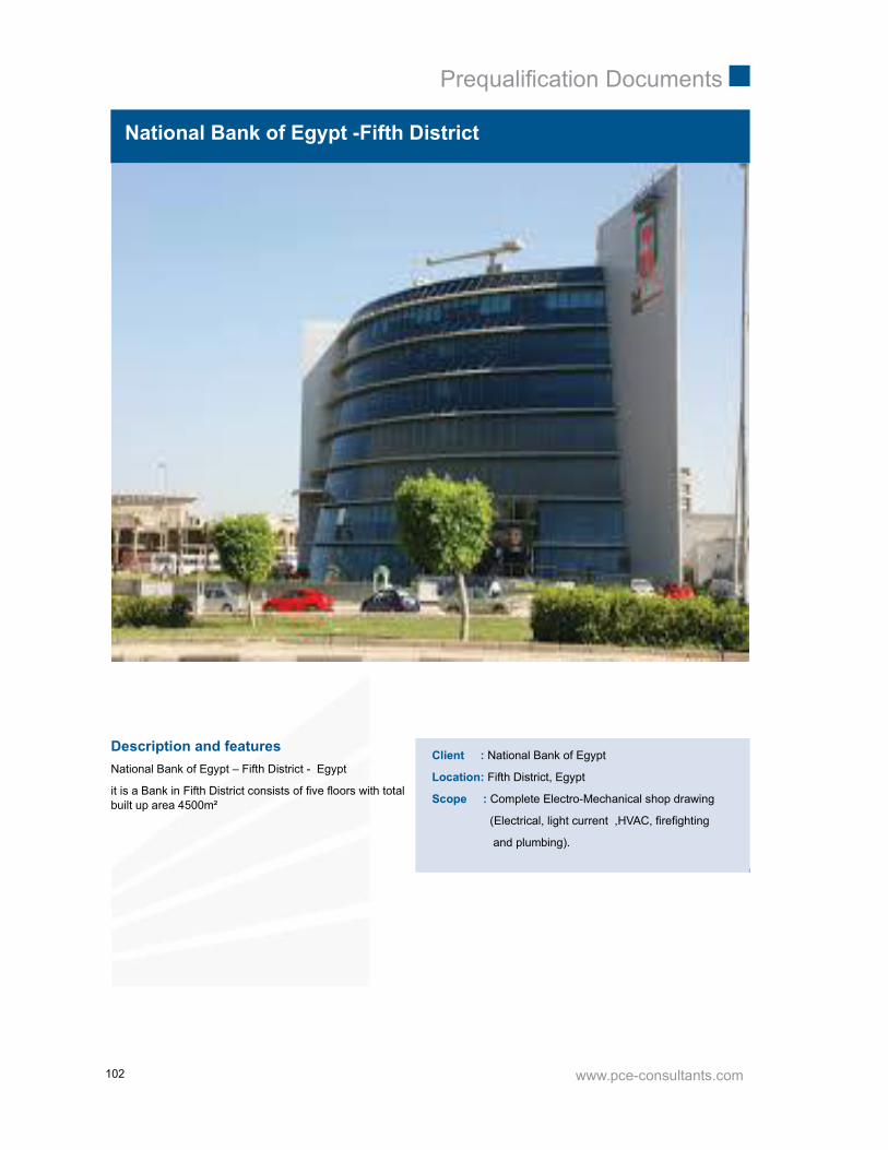
www.pce-consultants.com
Prequalifi cation Documents
102
Description and featuresNational Bank of Egypt – Fifth District - Egypt
it is a Bank in Fifth District consists of fi ve fl oors with totalbuilt up area 4500m²
Client : National Bank of Egypt
Location: Fifth District, Egypt
Scope : Complete Electro-Mechanical shop drawing
(Electrical, light current ,HVAC, fi refi ghting
and plumbing).
National Bank of Egypt -Fifth District

www.pce-consultants.com
Prequalifi cation Documents
103
Bank Faisal-Ismailia Branch
Description and featuresBank Faisal – Ismailia Branch - Egypt
GR + FR (1000 M2)
Client : Bank Faisal
Location: Ismailia , Egypt
Scope : Complete Electromechanical design and
Supervision (electrical, light current, HVAC,
fi refi ghting and plumbing)

www.pce-consultants.com
Prequalifi cation Documents
104
Landmark -Fifth District
Description and featuresIt is a hotel in Fifth District consist of seven fl oors with totalbuilt up area 250m²
Client : Landmark Company
Location: Fifth District, Egypt
Scope : Complete Electro-Mechanical design for the
Renovation (Electrical, light current, HVAC,
fi refi ghting and plumbing).

www.pce-consultants.com
Prequalifi cation Documents
105
ABHA Residential and Administrative Building
Client : Shikh Abo Hany
Location: Saudi Arabia
Scope : Complete Electro-Mechanical Design
(HVAC & Firefi ghting, Plumbing, Light Current,
Electrical, And Infrastructure Networks.).
Description and featuresIt is an administrative building consists of basement,ground and ten fl oors each is 1200m² built up area.

www.pce-consultants.com
Prequalifi cation Documents
106
Gnena-Administrative and commercial building-Phase II
Description and featuresAn administrative and commercial building, consists of
Two basements, ground, mezzanine, and another sevenfl oors each is 2750m², built up area
Built up area : 19250m²
Client : Genna Group
Location: Nasr City, Egypt
Scope : Complete shop drawings (HVAC, fi refi ghting
and plumbing)
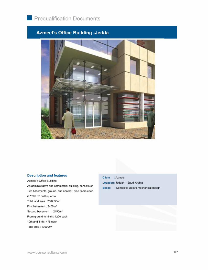
www.pce-consultants.com
Prequalifi cation Documents
107
Description and featuresAzmeel’s Offi ce Building
An administrative and commercial building, consists of
Two basements, ground, and another nine fl oors each
is 1200 m² built up area
Total land area : 2507.30m²
First basement : 2450m²
Second basement : 2450m²
From ground to ninth : 1200 each
10th and 11th : 475 each
Total area : 17900m²
Azmeel’s Offi ce Building -Jedda
Client : Azmeel
Location: Jeddah – Saudi Arabia
Scope : Complete Electro mechanical design

www.pce-consultants.com
Prequalifi cation Documents
108
Description and featuresRiyadh Public Control Center Building
I. Main Building :
Area : Approximately 6000 m²
Levels : 5 Levels (basement, ground, fi rst, second, roof)
Description : The project consists of main building dividedinto 4 branch building with 5 levels (basement ,
Ground, fi rst, second, roof) connected with each otherwith internal corridor ,The approximate area of the mainbuilding (6000) m² , There are service tunnel under themain building connected to the utility building with the mainbuilding by the basement level and connected to the watertank and fuel tank outside the building .The main buildinghave all the electromechanical system (fi re-plumping-HVAC-low current-power-lighting-piping) The building hasthe propeller shape which is the propeller blades is the 4buildings .
2. The MEP systems : Shop drawings will develop Therouting of the building system to follow the necessary paththat each system must take to reach its desired location.Most of this routing is determined by the design from thearchitectural fi and structural shop drawings .
Riyadh Public Transport Control Center
Client : Ministry of Higher Education
King Saud University
Location: Saudi Arabia
Scope : Complete electro mechanical Shop
Drawings
3. PCE : will ensure that all coordinated drawings areaccurately dimensioned, elevated and identifi ed. BIMSERVICES detailed scope for the main building drawingsincludes :
I. HVAC piping, valves, hangers and seismic bracing.
II. HVAC dry side and wet side equipment.
III. Plumbing waste and vent, domestic water.
IV. All the electrical and power systems .
V. Lighting fi xtures.
VI. Electrical panels and distribution equipment.
VII. Fire protection piping system .

www.pce-consultants.com
Prequalifi cation Documents
109
Description and features
Najeed Offi ces Building
It is an administrative building consists of basement,ground, mezzanine and fi rst fl oor.
Built up area 7000m²
Najeed Offi ces Building
Client : Najeed United
Location: Dammam – Saudi Arabia
Scope : Complete mechanical design
(HVAC, fi refi ghting and plumbing)

www.pce-consultants.com
Prequalifi cation Documents
110
Description and featuresWady El-Nile Administrative Building.
It is an administrative building in Heliopolis,
consists of four fl oors.
Built up area : 1500m²
Wady Elnile Admin Building
Client : Wadi EL-Nile
Location: Ismael El-Kabany, Heliopolis - Egypt
Scope : Complete electromechanical shop drawings
For fi re fi ghting and plumbing

www.pce-consultants.com
Prequalifi cation Documents
111
Hurghada City Center & Mixed Use Building-Hurgada
Description and featuresHurghada City Center& Mixed Use Building
A building consists of 8 levels with total area about60.000m²
Client : Arab Investment Company
Location: Hurghada - Egypt
Scope : Complete electromechanical shop
drawings
Status: Under Construction

www.pce-consultants.com
Prequalifi cation Documents
112
Description and featuresThe Grand Egyptian Museum (GEM), also known as theGiza Museum, is a planned museum of artifacts of ancientEgypt, described as the largest archaeological museum inthe world; the museum is scheduled to open in 2015.
The museum will be sited on 50 hectares (120 acres) ofland approximately two Kilometers from the Giza pyramids.
Built up area: 0.5Km²
Grand Egyptian Museum- 6th October
Client : The Egyptian Ministry of Antiquates
Location: Giza, Egypt
Scope : Complete fi refi ghting calculations