Embed Size (px)
Citation preview
PrePre
Energy Fuels REnergy Fuels R
PreparePrepare
Energy Fuels REnergy Fuels R44 Union Bo44 Union Bo
LakewoodLakewood
SubSubPreparePrepare
Golder AssoGolder Asso
November 2006
October 2008
Golder AGolder A44 Union Bo44 Union Bo
LakewoodLakewood
epared for:epared for:
Resources CorporationResources Corporation
ed by:ed by:
Resources CorporationResources Corporationoulevard, Suite 600oulevard, Suite 600
d, Colorado 80228d, Colorado 80228
bmitted by:bmitted by:
July 29, 2005053-2348
ed by:ed by:
ociates Inc.ociates Inc.
063-219
073-81694.0004
Associates Inc.Associates Inc.oulevard, Suite 300oulevard, Suite 300
d, Colorado 80228d, Colorado 80228

Golder Associates Inc. 44 Union Boulevard, Suite 300 Lakewood, CO USA 80228 Telephone: (303) 980-0540 Fax: (303) 985-2080 www.golder.com
OFFICES ACROSS AFRICA, ASIA, AUSTRALIA, EUROPE, NORTH AMERICA AND SOUTH AMERICA
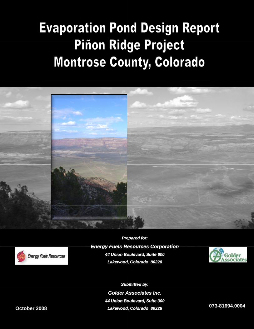
EVAPORATION POND DESIGN REPORT PIÑON RIDGE PROJECT
MONTROSE COUNTY, COLORADO
Submitted to:
Energy Fuels Resources Corporation 44 Union Boulevard, Suite 600 Lakewood, Colorado 80228
Submitted by:
Golder Associates Inc. 44 Union Boulevard, Suite 300 Lakewood, Colorado 80228
October 2008 073-81694.0004

October 2008 ES-1 073-81694.0004
i:\07\81694\0400\designrep-evappond-fnl_07oct08\designrep-evappond-fnl_07oct08.docx Golder Associates
EXECUTIVE SUMMARY
Energy Fuels Resources Corporation (EFRC) is in the process of completing designs for a uranium
mill, termed the Piñon Ridge Project, located in Montrose County, Colorado. Golder Associates Inc.
(Golder) was contracted to provide geotechnical design for construction of the tailings cells,
evaporation ponds and ore pads at the Piñon Ridge Project. Golder’s evaporation pond design scope
of work includes:
• Conducting a geotechnical field and laboratory test investigation of the proposed evaporation pond area (Golder, 2008a);
• Reviewing available data and regulatory requirements, and development of project design criteria;
• Conducting engineering analyses and design for the evaporation ponds, including probabilistic water balance modeling, design of liner systems, design of leak collection and recovery systems, and water fowl protection design; and
• Development of design drawings and specifications for potential two-phased construction of the evaporation ponds, with the first phase designed for 500 ton per day (tpd) operations, with potential for expansion to an ultimate capacity of 1,000 tpd.
The plan area of the lined portion of each evaporation pond is 4.13 acres, with a total Phase I lined
area of 41.3 acres and a total combined Phase I/Phase II lined area of 82.6 acres. The evaporation
ponds have been designed with measures to enhance evaporation, including installation of black
geomembrane liner and operation of sprinklers.
The evaporation ponds are each designed with a primary and secondary liner system and an
intervening leak collection and recovery system (LCRS). The LCRS design provides for capture and
conveyance of the seepage through the upper primary liner to a collection sump. LCRS sumps have
been included in the design of each evaporation pond cell. Solution collected in the LCRS sumps will
be pumped using a mobile pump, and returned to the evaporation ponds.

October 2008 -i- 073-81694.0004
i:\07\81694\0400\designrep-evappond-fnl_07oct08\designrep-evappond-fnl_07oct08.docx Golder Associates
TABLE OF CONTENTS
EXECUTIVE SUMMARY ...................................................................................................... ES-1
1.0 INTRODUCTION .............................................................................................................. 1 1.1 Scope of Work .................................................................................................................... 1 1.2 Property Location ............................................................................................................... 1
2.0 GENERAL SITE CONDITIONS ...................................................................................... 2 2.1 Climate ................................................................................................................................ 2 2.2 Geotechnical Conditions ..................................................................................................... 3
3.0 EVAPORATION POND DESIGN ................................................................................... 5 3.1 Design Criteria .................................................................................................................... 5
3.1.1 Design Regulations ...................................................................................................... 5 3.1.2 Project Design Criteria ................................................................................................. 5
3.2 Design Concepts ................................................................................................................. 6 3.2.1 General Evaporation Pond Design Concepts ............................................................... 6 3.2.2 Surface Water Control Design Concepts ...................................................................... 8 3.2.3 Closure Design Concepts ............................................................................................. 8
3.3 Liner System Design ........................................................................................................... 8 3.3.1 Upper (Primary) Liner .................................................................................................. 9 3.3.2 Leak Collection and Recovery System ........................................................................ 9 3.3.3 Lower (Secondary) Composite Liner System ............................................................ 10
3.4 Leak Collection and Recovery System Design ................................................................. 11 3.5 Water Balance Modeling .................................................................................................. 12 3.6 Bird Netting Design .......................................................................................................... 13
4.0 CONSTRUCTION CONSIDERATIONS ...................................................................... 14 4.1 Geomembrane Exposure ................................................................................................... 14 4.2 GCL Underliner Construction Considerations .................................................................. 15 4.3 Electrical Leak Integrity Survey ....................................................................................... 16
5.0 USE OF THIS REPORT .................................................................................................. 17
6.0 REFERENCES ................................................................................................................. 18

October 2008 -ii- 073-81694.0004
i:\07\81694\0400\designrep-evappond-fnl_07oct08\designrep-evappond-fnl_07oct08.docx Golder Associates
LIST OF TABLES
Table 1 Monthly Precipitation and Evaporation Values Table 2 Designed Leachate Compositions
LIST OF FIGURES Figure 1 Evaporation Pond Stage-Storage Data Figure 2 Water Balance Flow Sheet
LIST OF DRAWINGS
Drawing 1 Title Sheet with Drawing List and Location Map Drawing 2 General Project Layout and Locations of Geotechnical Investigations Drawing 3 Phase I Excavation Grading Plan and Isopach Drawing 4 Phase II Excavation Grading Plan and Isopach Drawing 5 Evaporation Pond Typical Sections Drawing 6 Bird Netting Plan and Details Drawing 7 Bird Netting Details Drawing 8 Evaporation Pond Liner Details Drawing 9 Leak Collection and Recovery System Sections and Details
LIST OF APPENDICES Appendix A Water Balance Evaluation
Appendix A-1 Climate Data Analysis Appendix B Action Leakage Rate
Appendix B-1 Action Leakage Rate Calculation Appendix C Water Fowl Protection System
Appendix C-1 Bird Netting Design Calculations Appendix C-2 Ice Loading Evaluation
Appendix D Chemical Resistance Information Appendix D-1 Chemical Resistance Chart
Appendix E Leak Collection and Recovery System Design Appendix E-1 Leak Collection and Recovery System Sump Capacity Calculation
October 2008 -1- 073-81694.0004
i:\07\81694\0400\designrep-evappond-fnl_07oct08\designrep-evappond-fnl_07oct08.docx Golder Associates
1.0 INTRODUCTION
Energy Fuels Resources Corporation (EFRC) is in the process of completing designs for a new
uranium mill, termed the Piñon Ridge Project, located in Montrose County, Colorado. Golder
Associates Inc. (Golder) was contracted to provide geotechnical design for construction of the tailings
cells, evaporation ponds and ore pads at the Piñon Ridge Project.
1.1 Scope of Work
Golder’s evaporation pond design scope of work includes:
• Conducting a geotechnical field and laboratory test investigation of the proposed evaporation pond area (Golder, 2008a);
• Reviewing available data and regulatory requirements, and development of project design criteria;
• Conducting engineering analyses and design for the evaporation ponds, including probabilistic water balance modeling, design of liner systems, design of leak collection and recovery systems, and water fowl protection design; and
• Development of design drawings and specifications for potential two-phased construction of the evaporation ponds, with the first phase designed for 500 ton per day (tpd) operations, with potential for expansion to an ultimate production rate of 1,000 tpd.
The plan area of the lined portion of each evaporation pond is 4.13 acres, with a total Phase I lined
area of 41.3 acres and a total combined Phase I/Phase II lined area of 82.6 acres.
1.2 Property Location
The Piñon Ridge Project is located in Montrose County, Colorado in the Paradox Valley,
approximately 15 miles northwest of the town of Naturita on Highway 90. The physical address of
the site is 16910 Highway 90; Bedrock, Colorado. The approximate site location is: latitude
38o 15’ N, longitude 108o 46’ W; and elevation 5,500 feet above mean sea level (amsl). The property
is located within Sections 5, 8, and 17, Township 46 North, and Range 17 West. The site lies in the
gently sloping base of the northwest-trending Paradox Valley with steep ridges on either side.
Drawing 1 presents a general location map for the Piñon Ridge property.

October 2008 -2- 073-81694.0004
i:\07\81694\0400\designrep-evappond-fnl_07oct08\designrep-evappond-fnl_07oct08.docx Golder Associates
2.0 GENERAL SITE CONDITIONS
The site terrain is gently sloping toward the north, with shallow to moderately incised arroyos across
the property. The northern half of the site is generally covered in dense sagebrush while the southern
half is sparsely vegetated with grass and cacti.
The Paradox Valley was formed by an anticline heavy in evaporites. As the evaporites began to
dissolve, part of the anticline sank forming the Paradox Valley. The bedrock underlying the site
primarily consists of claystone and gypsum of the Hermosa Formation. The gypsum generally shows
a massive texture, whereas the claystone is typically highly fractured. Less significant zones of
sandstone, siltstone and claystone of the Cutler and Moenkopi Formations were also found across the
Piñon Ridge Project site during the field investigation. Groundwater in the vicinity of the evaporation
ponds is greater than 600 feet below the ground surface, as the prevalence of the Hermosa Formation
increases toward the northern portion of the site, and hence the thickness of the non-water-bearing
gypsum unit.
2.1 Climate
The macro-climate of the Piñon Ridge Project area is classified by the Koppen Climate Classification
System as a BSk, which indicates a semi-arid steppe with much of the characteristics of a desert
(Kleinfelder, 2007a).
Meteorological towers have been installed on-site to provide baseline site data; however, on-site
climatic data is not yet available. Golder conducted a review of climatic data obtained from the
Western Regional Climate Center for the Uravan, Nucla, Grand Junction (Airport and 6 ESE), and
Montrose weather stations. The evaluation of climate data for these nearby weather stations indicates
that the Uravan weather station is likely to provide reasonable precipitation estimates for the site (see
Appendix A-1). Climatic data available for the Uravan weather station included precipitation, air
temperature, and snow cover for the years of record of 1960 through 2007. The Hargreaves (1985)
method was used to estimate monthly evaporation values at the Piñon Ridge site, using the available
climate data from Uravan. The calculated evaporation values were scaled by a factor of 0.7 to
represent lake evaporation. The average monthly climatic data used for design of the Piñon Ridge
facilities is summarized in Table 1. Considering this climatic data, the annual evaporation exceeds
annual precipitation on average by about three times.
October 2008 -3- 073-81694.0004
i:\07\81694\0400\designrep-evappond-fnl_07oct08\designrep-evappond-fnl_07oct08.docx Golder Associates
The predominant wind directions for the site are east and east-southeast, with an average annual wind
speed of 5.3 miles per hour (mph) (Kleinfelder, 2007b). The maximum wind speed used for facility
design is 23.4 mph, which was recorded at the Grand Junction weather station (see Appendix A-1).
2.2 Geotechnical Conditions
A geotechnical investigation was conducted by Kleinfelder West Inc. (Kleinfelder) and Golder in
accordance with Criterion 5(G)(2), 6 CCR 1007 Part 18. Phase 1 of the investigation was directed by
Kleinfelder to develop general characterization of the site. Phase 2 was conducted jointly by
Kleinfelder and Golder to support geotechnical design work for the site, including the evaporation
ponds.
As part of the Phase 1 geotechnical investigations, Kleinfelder drilled twenty (20) geotechnical
boreholes (PR1-1 to PR-20) spaced across the site to depths ranging from 30.3 to 98.8 feet below the
ground surface, installed six monitoring wells (MW-1 to MW-6) at depths of 100 to 600 feet below
the ground surface, and completed three seismic reflection/refraction geophysical lines trending
north-south across the site.
The Phase 2 geotechnical field investigation conducted by Golder (2008a) consisted of 48 drill holes
and 11 test pits within the proposed tailings cells, evaporation pond, and ore pad areas. The
geotechnical conditions encountered in the 17 drill holes (GA-BH-01 through GA-BH-17) completed
in the evaporation pond area consisted of bedrock depths ranging from 14.5 feet to 67 feet. Bedrock
was not encountered in several borings at exploration depths ranging from 50 to 70 feet. The
overburden soils generally consist of windblown loess (i.e., ML, SM, SW, CL) with occasional layers
of alluvium (i.e., GM, SM). Bedrock generally consisted of claystone, gypsum, and siltstone of the
Hermosa Formation. Blowcounts in the overburden materials underlying the evaporation pond area
ranged from 3 to refusal (i.e., greater than 50 blows per 6 inches).
Findings from the geotechnical investigations reveal the following general site characteristics:
• Groundwater was encountered in a few monitoring wells (MW-6, MW-7, MW-8 and MW-9) on the southern portion of the site, with no groundwater encountered to the north of these wells. The depth to groundwater was between 340 and 400 feet below the ground surface in these wells. The groundwater has a high sulfur content. Holes drilled within the evaporation pond area at the northern end of the property went as deep as 600 feet without encountering groundwater.
October 2008 -4- 073-81694.0004
i:\07\81694\0400\designrep-evappond-fnl_07oct08\designrep-evappond-fnl_07oct08.docx Golder Associates
• The site is underlain by a number of aquitards. Additionally, evaporite rock of the Hermosa Group, which does not host any measurable amount of water, underlies the proposed location of the evaporation ponds. This geological feature significantly reduces any potential impact to groundwater during the Mill’s “Active Life” (as defined in Criterion 5A of Appendix A to include the closure period).
• While the geophysical investigation identified some possible fault traces underlying the proposed evaporation pond area, trenching and mapping confirmed that these features are overlain by a minimum of 20 feet of undisturbed alluvial/colluvial soil. Accordingly, this data confirms that the potential faults are at least 10 million years old and can be classified as “non capable faults” as defined in section III(g) of Appendix A of 10 CFR Part 100.
October 2008 -5- 073-81694.0004
i:\07\81694\0400\designrep-evappond-fnl_07oct08\designrep-evappond-fnl_07oct08.docx Golder Associates
3.0 EVAPORATION POND DESIGN
This section provides the engineering analyses and technical details to support design of the
evaporation ponds for the Piñon Ridge Project.
3.1 Design Criteria
3.1.1 Design Regulations
Regulations relevant to the design of the evaporation ponds presented here in Section 3.0 are
summarized below.
Key Regulatory Agencies and Documents:
Colorado Department of Public Health and Environment (CDPHE): 6 CCR 1007-1, Part 18 –
“State Board of Health Licensing Requirements for Uranium and Thorium Processing”,
specifically Appendix A (Criteria relating to the operation of mills and the disposition of the
tailings or wastes from these operations).
Environmental Protection Agency (EPA): 40 CFR Part 264 – “Standards for Owners and
Operators of Hazardous Waste Treatment, Storage, and Disposal Facilities”, Subpart K (Surface
Impoundments); and 40 CFR Part 192 – “Health and Environmental Protection Standards for
Uranium and Thorium Mill Tailings”, Subpart D (Standards for management of uranium
byproduct materials pursuant to section 84 of the Atomic Energy Act of 1954, as amended).
Note: Per Rule 17 (Exempt Structures) of the State of Colorado, Department of Natural Resources, Division of Water Resources (Office of the State Engineer [OSE], 2007) “Rules and Regulations for Dam Safety and Dam Construction”, uranium mill tailing and liquid impoundment dams are exempt from these rules with permitting authority provided by the Colorado Department of Public Health and Environment (CDPHE).
3.1.2 Project Design Criteria
Design criteria relevant to the analyses presented here in Section 3.0 are summarized below.
Geometry:
Milling Operations: Design capacity of 500 tons per day (tpd) of tailings disposal, with potential expansion capacity to 1,000 tpd.
October 2008 -6- 073-81694.0004
i:\07\81694\0400\designrep-evappond-fnl_07oct08\designrep-evappond-fnl_07oct08.docx Golder Associates
Evaporation Pond Storage Capacity: 256 acre-feet for Phase I (i.e., 25.6 acre-feet per cell), with potential expansion to 512 acre-feet (see Figure 1).
Maximum Evaporative Surface Area: 41.3 acres for Phase I (i.e., 4.1 acres per cell), with potential expansion to 82.6 acres.
Mill Design Life: 40 years (dependent upon milling rate).
Raffinate Stream Properties:
Design Volumetric Flow Rate: 63 gallons per minute (gpm) at a milling capacity of 500 tpd, with 126 gpm at an ultimate milling capacity of 1000 tpd.
System Requirements:
Evaporation Pond Liner System: Double layer liner system as follows (top to bottom): (1) upper (primary) geomembrane liner; (2) leak collection and recovery system; (3) lower (secondary) geomembrane liner; underlain by (4) minimum three feet of low permeability soil liner with a hydraulic conductivity no more than 1x10⁻⁷ centimeters per second (cm/sec), or approved equivalent (per 40 CFR 264.221 by reference from 10 CFR 40 and 6 CCR 1007-1, Part 18).
Leak Collection and Recovery System: Per 40 CFR 264.221 (by reference from 10 CFR 40 and 6 CCR 1007-1, Part 18), the leak detection system shall meet the following requirements: (1) constructed with a bottom slope of one percent or more; (2) constructed of granular drainage materials with a hydraulic conductivity of 1x10⁻¹ cm/sec or greater and a thickness of 12 inches or more, or constructed of a synthetic or geonet drainage material with a transmissivity of 3x10⁻⁴ square meters per second (m2/sec) or more; (3) constructed of materials that are chemically resistant to the waste and leachate; (4) designed and operated to minimize clogging during the active life and post-closure care period; and (5) constructed with sumps and liquid removal methods (i.e., pumps).
3.2 Design Concepts
This section presents the general evaporation pond design concepts with the technical details for these
concepts discussed in detail in the following sections.
3.2.1 General Evaporation Pond Design Concepts
The Piñon Ridge Mill is designed for start-up operations at 500 tons per day (tpd), with a potential to
expand to 1,000 tpd. The design raffinate flows from the process circuit (CH2M Hill, 2008), which
includes water collected from the tailings cells in excess of that needed for re-circulation to the mill,
will be discharged to the evaporation ponds. The design flow rates associated with the start-up and
ultimate production rates are 63 and 126 gallons per minute (gpm), respectively. The average
volumetric flow rate to the evaporation ponds for the 1,000 tpd scenario is somewhat less at 117 gpm.
October 2008 -7- 073-81694.0004
i:\07\81694\0400\designrep-evappond-fnl_07oct08\designrep-evappond-fnl_07oct08.docx Golder Associates
The evaporation pond system is designed for construction in two phases. Phase I includes 10 ponds
(or cells), each with a surface dimension of 300 feet by 600 feet (i.e., 4.13 acres), designed to
evaporate the inflows associated with the 500 tpd production schedule. Similarly, Phase II includes
an additional 10 ponds with the same dimensions designed to evaporate the flows associated with the
1,000 tpd production schedule. Both phases of construction are designed to provide contingency
storage for the 1,000-year storm event acting over the respective pond area, with an additional one
foot of freeboard (above the required design capacities). Pond berms with a minimum crest width of
15 feet are designed between ponds to allow access from all sides of the cells, as well as installation
of bird netting supports. All of the evaporation ponds are designed at the same elevation, allowing for
gravity flow of the raffinate from the inlet pond (i.e., the southeastern-most pond cell) to all other
ponds. Consequently, the water depth in each pond will be similar, maximizing the evaporative
surface area. Leak collection and recovery system (LCRS) sumps have been included in the design of
each evaporation pond cell. Solution collected in the LCRS sumps will be pumped using a mobile
pump, and returned to the evaporation ponds.
In order to improve performance of the evaporation pond system (i.e., enhance the evaporative
capabilities), the design includes implementation of a sprinkler system. The sprinklers will be placed
and sized to maximize evaporation and minimize the potential for wind-drift beyond the extents of the
lined evaporation pond area. A continuous liner is designed over the entire evaporation pond area,
including over the separation berms. A textured geomembrane will be extrusion welded on top of the
berms between pond cells to facilitate access (i.e., pedestrian or ATV).
Measures taken to limit water fowl from accessing the evaporation ponds included design of a bird
netting system. The individual pond cell dimensions of 300 feet by 600 feet were selected based on
the maximum practical span for the bird netting system. The bird netting system will consist of
wooden support poles spaced approximately 48 feet apart along the 15-foot wide pond divider berms,
designed to elevate and support the primary cable system. A secondary cable system will link the
primary cables, creating a cable grid over which the netting can then be placed. The base of each
wooden support pole will be sealed to prevent raffinate infiltration around the liner at the pole
locations. The bird netting is designed with two-inch openings to prevent access from water fowl.
Drawings 6 and 7 provide details for installation of the bird netting system for both Phases I and II.
Bird netting system design details are discussed in greater detail in Section 3.6.
October 2008 -8- 073-81694.0004
i:\07\81694\0400\designrep-evappond-fnl_07oct08\designrep-evappond-fnl_07oct08.docx Golder Associates
3.2.2 Surface Water Control Design Concepts
Site-wide surface water design was conducted by Kleinfelder, and will be presented under separate
cover. Surface water run-on into the evaporation ponds includes surface water run-off from the
perimeter berms, direct precipitation onto the evaporation pond area, and stormwater overflow via a
spillway and channel (or pipe) from the West Stormwater Pond. The West Stormwater Pond is
designed to contain the 100-year storm event, with runoff in excess of the 100-year storm event (up to
the 1,000-year storm event) reporting to the evaporation pond system.
3.2.3 Closure Design Concepts
The closure plan for the evaporation ponds at the Piñon Ridge Project has been designed and
integrated with the closure plan for the tailings cells. Closure of the evaporation ponds includes
excavation and disposal of geosynthetic materials into the tailings cells as well as removal and
disposal of the upper 12 inches of soil below the liner system. After excavation and disposal of the
aforementioned materials into the tailings cells, the evaporation pond area will be regraded and
revegetated to tie in with the natural landscape.
More detailed information on the tailings cells closure and the evaporation ponds disposal can be
found in the Tailings Cell Design Report (Golder, 2008d).
3.3 Liner System Design
As noted previously, investigative drilling to depths of up to 600 feet below the ground surface did
not encounter any groundwater under the planned location of the evaporation ponds. The nearest
discovery of groundwater was 3,200 feet south of the evaporation pond location. Additionally, a
number of aquitards were identified during the geotechnical field investigation, further limiting any
potential impacts to the groundwater regime during the “Active Life” of the Mill. However, as noted
in Golder (2008a), the evaporation pond area is underlain by varying thicknesses of collapsible soils
and therefore the evaporation ponds were conservatively designed applying the same standards as
those required for the tailings cells (i.e., 40 CFR 264.221, by reference from 10 CFR 40 and
6 CCR 1007-1 [Part 18]). The evaporation pond design utilizes a double liner system with an
intervening Leak Collection and Recovery System (LCRS) for groundwater protection and enhanced
seepage protection, as follows (from top to bottom):
October 2008 -9- 073-81694.0004
i:\07\81694\0400\designrep-evappond-fnl_07oct08\designrep-evappond-fnl_07oct08.docx Golder Associates
• 60-mil high density polyethylene (HDPE) upper (primary) geomembrane;
• LCRS consisting of HDPE geonet;
• 60-mil HDPE lower (secondary) geomembrane;
• Reinforced geosynthetic clay liner (GCL) as the underliner component of the secondary composite liner system; and
• Prepared subgrade.
Liner system details for the evaporation ponds are provided on Drawing 8.
3.3.1 Upper (Primary) Liner
The upper primary liner will consist of a conductive smooth 60-mil HDPE geomembrane. An HDPE
liner was chosen for its long term performance due to its chemical resistance properties (see Chemical
Resistance Charts in Appendix D), resistance to ultraviolet radiation, high tensile strength, and high
stress-crack resistance (Lupo & Morrison, 2005). The evaporation pond liner will be exposed for the
life of the mine (i.e., 20 to 40 years), and was therefore designed for long-term solar radiation
exposure (see Section 4.1 and Golder, 2008b). To facilitate quality assurance during installation of
the liner system, the upper primary geomembrane liner will be conductive to facilitate spark testing of
the liner surface upon completion of the installation (see Section 4.2). A standard black HDPE
geomembrane will be employed as the upper (primary) liner for increased heat retention to enhance
evaporation potential.
3.3.2 Leak Collection and Recovery System
An important feature of the evaporation pond liner system is the Leak Collection and Recovery
System (LCRS) layer, designed per 40 CFR 264.221 (by reference from 10 CFR 40 and
6 CCR 1007-1, Part 18). If a leak occurs in the upper primary geomembrane, the LCRS is designed
to minimize the hydraulic heads on the lower geomembrane liner by utilization of HDPE geonet.
In the event that leakage occurs through the upper geomembrane liner, it will be collected in the
LCRS layer and routed (via gravity flow) to a LCRS sump located in each evaporation pond cell. The
LCRS design is discussed in greater detail in Section 3.4.
October 2008 -10- 073-81694.0004
i:\07\81694\0400\designrep-evappond-fnl_07oct08\designrep-evappond-fnl_07oct08.docx Golder Associates
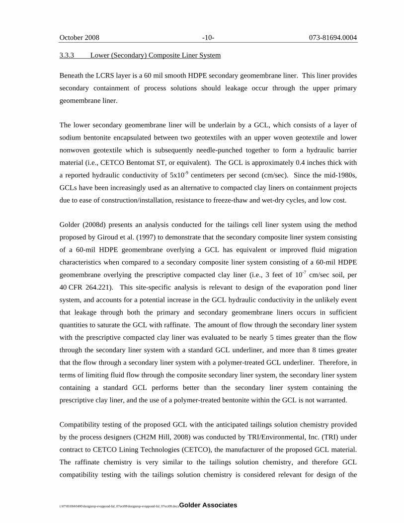
3.3.3 Lower (Secondary) Composite Liner System
Beneath the LCRS layer is a 60 mil smooth HDPE secondary geomembrane liner. This liner provides
secondary containment of process solutions should leakage occur through the upper primary
geomembrane liner.
The lower secondary geomembrane liner will be underlain by a GCL, which consists of a layer of
sodium bentonite encapsulated between two geotextiles with an upper woven geotextile and lower
nonwoven geotextile which is subsequently needle-punched together to form a hydraulic barrier
material (i.e., CETCO Bentomat ST, or equivalent). The GCL is approximately 0.4 inches thick with
a reported hydraulic conductivity of 5x10⁻⁹ centimeters per second (cm/sec). Since the mid-1980s,
GCLs have been increasingly used as an alternative to compacted clay liners on containment projects
due to ease of construction/installation, resistance to freeze-thaw and wet-dry cycles, and low cost.
Golder (2008d) presents an analysis conducted for the tailings cell liner system using the method
proposed by Giroud et al. (1997) to demonstrate that the secondary composite liner system consisting
of a 60-mil HDPE geomembrane overlying a GCL has equivalent or improved fluid migration
characteristics when compared to a secondary composite liner system consisting of a 60-mil HDPE
geomembrane overlying the prescriptive compacted clay liner (i.e., 3 feet of 10-7 cm/sec soil, per
40 CFR 264.221). This site-specific analysis is relevant to design of the evaporation pond liner
system, and accounts for a potential increase in the GCL hydraulic conductivity in the unlikely event
that leakage through both the primary and secondary geomembrane liners occurs in sufficient
quantities to saturate the GCL with raffinate. The amount of flow through the secondary liner system
with the prescriptive compacted clay liner was evaluated to be nearly 5 times greater than the flow
through the secondary liner system with a standard GCL underliner, and more than 8 times greater
that the flow through a secondary liner system with a polymer-treated GCL underliner. Therefore, in
terms of limiting fluid flow through the composite secondary liner system, the secondary liner system
containing a standard GCL performs better than the secondary liner system containing the
prescriptive clay liner, and the use of a polymer-treated bentonite within the GCL is not warranted.
Compatibility testing of the proposed GCL with the anticipated tailings solution chemistry provided
by the process designers (CH2M Hill, 2008) was conducted by TRI/Environmental, Inc. (TRI) under
contract to CETCO Lining Technologies (CETCO), the manufacturer of the proposed GCL material.
The raffinate chemistry is very similar to the tailings solution chemistry, and therefore GCL
compatibility testing with the tailings solution chemistry is considered relevant for design of the

October 2008 -11- 073-81694.0004
i:\07\81694\0400\designrep-evappond-fnl_07oct08\designrep-evappond-fnl_07oct08.docx Golder Associates
evaporation ponds. For reference, Table 2 summarizes the chemistry of the two solutions. Results of
this testing program indicate that the anticipated tailings leachate may result in an increase to the
permeability of the standard GCL from 5x10⁻⁹ cm/sec to approximately 1.1x10⁻⁸ cm/sec. Testing of a
polymer-treated GCL in contact with the anticipated tailings leachate indicates negligible change in
GCL permeability. A more detailed description of the GCL compatibility testing program is provided
in Golder (2008d).
3.4 Leak Collection and Recovery System Design
As part of the evaporation pond design, a leak collection and recovery system (LCRS) has been
incorporated to meet the requirements of the regulations. If a leak occurs in the upper primary
geomembrane, the LCRS is designed to minimize the hydraulic heads on the lower geomembrane
liner. Details of the LCRS system are shown on Drawing 9.
The LCRS layer has been designed as an HDPE geonet with a minimum transmissivity of
2x10⁻³ square meters per second (m2/sec), which exceeds the minimum transmissivity requirement of
3x10⁻⁴ m2/sec (per 40 CFR 264.221). The drainage layer is designed with a thickness of 200 mil.
In the event that leakage occurs through the upper geomembrane liner, it will be collected in the
LCRS layer and routed (via gravity flow) to a LCRS sump located in each evaporation pond cell. The
LCRS sumps were conservatively sized using a minimum base dimension of 10 feet for
constructability. The sump for each evaporation pond cell is designed to have base dimensions of
10 feet by 30 feet, 3H:1V side slopes, and a 5-foot depth based on the designed grading for the pond
cells (i.e., flat portions of the cell are underlain by the LCRS sump). The LCRS sump provides
capacity for approximately 14 days of anticipated leakage (see LCRS sump sizing calculation in
Appendix E), which facilitates use of a mobile pump for removal of leak solution, and return to the
evaporation ponds.
Two LCRS riser pipes are provided within each sump to add redundancy to the system. The risers
consist of 10-inch diameter, SDR-17 HDPE pipes. The lower ends of the pipes are slotted in the
sump area to provide solution access into the risers. Solution is recovered via a mobile submersible
pump (designed by others) which will be installed in the riser as needed. The LCRS risers will be
instrumented and fully-automated to report to the mill control system with an alarm in the mill.
Recovered solutions will be returned to the evaporation pond system.

October 2008 -12- 073-81694.0004
i:\07\81694\0400\designrep-evappond-fnl_07oct08\designrep-evappond-fnl_07oct08.docx Golder Associates
Action Leakage Rates (ALRs) were evaluated for the LCRS sump using the guidelines published by
the U.S. Environmental Protection Agency (EPA, 1992). The ALR is defined in 40 CFR 264.222 as
“the maximum design flow rate that the leak detection system (LDS) can remove without the fluid
head on the bottom liner exceeding 1 foot.” The ALR calculations are provided in Appendix B.
Based on these calculations, the ALR for the LCRS sump contained within each evaporation pond
cell is 12,000 gallons per acre per day (gpad).
3.5 Water Balance Modeling
Golder developed a probabilistic water balance to assist in sizing of the evaporation pond system (i.e.,
required evaporative surface area). Water balance calculations were performed using the computer
program Goldsim™, and are presented in detail in Appendix A.
The following water balance components were considered: (1) the amount of raffinate water entering
the pond system from the mill (CH2M Hill, 2008), (2) water entering the system through meteoric
precipitation, and (3) the amount of water released to the atmosphere through evaporation.
Precipitation values are likely to exhibit largest variations, and were therefore treated as stochastic
inputs (i.e., probabilistic), while the other parameters were treated as deterministic variables. Figure 2
presents the process flow diagram for the evaporation pond water balance.
Preliminary analyses revealed a prohibitively large evaporation area for extreme precipitation events
when considering evaporation losses solely from the pond surface. To reduce the required
evaporative area, subsequent analyses included a sprinkler system resulting in enhanced evaporation
losses. All sprinkler heads will be located a minimum of 300 feet from the edge of the lined
evaporation pond area to minimize the probability of wind-drift blowing the raffinate beyond the
lined evaporation pond area.
The results of the water balance were calculated assuming a four percent (4%) chance of exceedance
(requiring mill shutdown) over the maximum anticipated mill life of 40 years, which is the probability
that the 1,000-year storm event will occur during the operational period. Based on this assumption,
the required evaporative areas for milling operations of 500 and 1,000 tons per day were calculated to
be 45.5 and 82.6 acres, respectively. The Phase I evaporation pond design provides 41.3 acres of
pond surface area, a reduction from the calculated 45.5 acres. This deviation from the calculated
value is based on the assumption that mill expansion to 1,000 tpd will occur by the end of year 10 of
operations (see Table A-7 in Appendix A). However, field measurements during the early years of

October 2008 -13- 073-81694.0004
i:\07\81694\0400\designrep-evappond-fnl_07oct08\designrep-evappond-fnl_07oct08.docx Golder Associates
milling will assist in optimization of the required evaporation pond area, and an additional cell (or
cells) will be added for the designed 500 tpd milling rate as needed to accommodate actual site
conditions.
The influence of potential bird netting and the presence of dissolved solids in the process flow to the
evaporation ponds are both likely to affect pond evaporation. Thus, the need to provide field
evaporation measurements during the early years of milling operations is warranted. These field
measurements will assist in refining expansion design of the evaporation ponds for an increase to
1,000 tpd operations.
3.6 Bird Netting Design
The acidic solution contained within the evaporation ponds represents a potential threat to endangered
birds and migratory waterfowl. Birds view these ponds as an opportunity to rest and feed. If allowed
to land, the birds may become poisoned by getting into contact with chemicals present in the
evaporation ponds. This situation creates a liability under the Migratory Bird Treaty Act
(U.S. Congress, 1976). In order to limit bird mortality, a bird netting system was designed to reduce
water fowl access to the evaporation ponds. Design of the water fowl protection system is presented
in detail in Appendix C. Details of the bird netting system are illustrated in Drawings 6 and 7.
October 2008 -14- 073-81694.0004
i:\07\81694\0400\designrep-evappond-fnl_07oct08\designrep-evappond-fnl_07oct08.docx Golder Associates
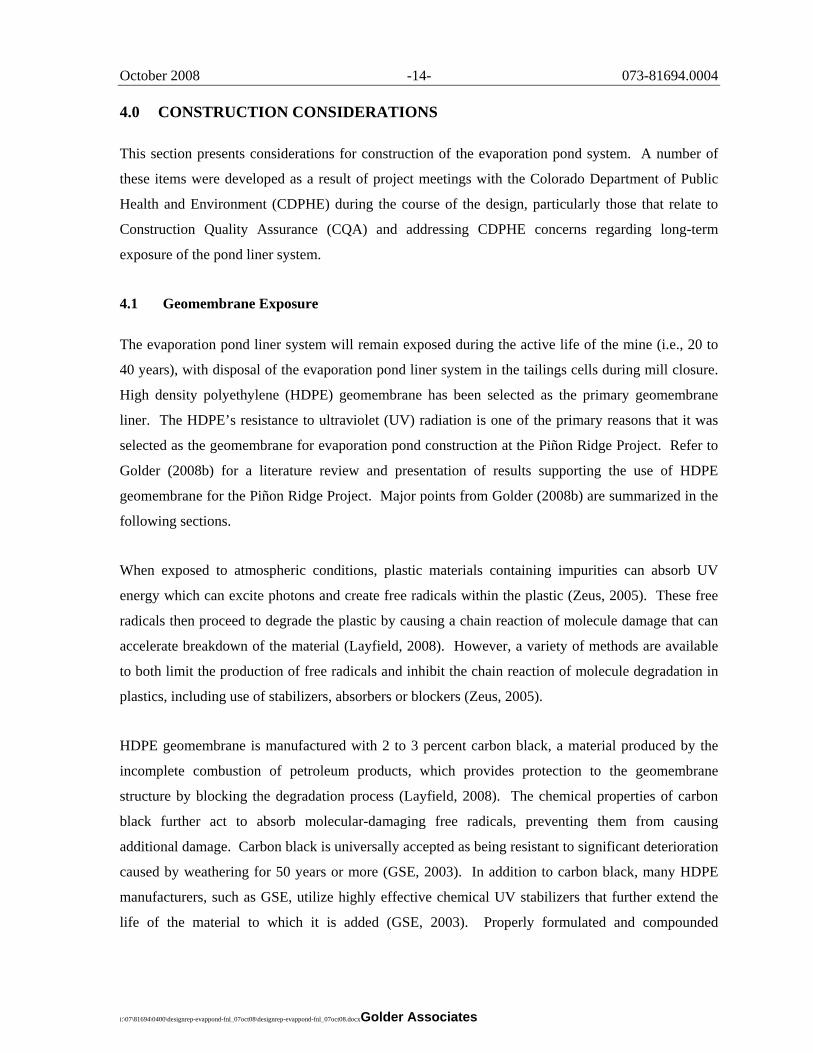
4.0 CONSTRUCTION CONSIDERATIONS
This section presents considerations for construction of the evaporation pond system. A number of
these items were developed as a result of project meetings with the Colorado Department of Public
Health and Environment (CDPHE) during the course of the design, particularly those that relate to
Construction Quality Assurance (CQA) and addressing CDPHE concerns regarding long-term
exposure of the pond liner system.
4.1 Geomembrane Exposure
The evaporation pond liner system will remain exposed during the active life of the mine (i.e., 20 to
40 years), with disposal of the evaporation pond liner system in the tailings cells during mill closure.
High density polyethylene (HDPE) geomembrane has been selected as the primary geomembrane
liner. The HDPE’s resistance to ultraviolet (UV) radiation is one of the primary reasons that it was
selected as the geomembrane for evaporation pond construction at the Piñon Ridge Project. Refer to
Golder (2008b) for a literature review and presentation of results supporting the use of HDPE
geomembrane for the Piñon Ridge Project. Major points from Golder (2008b) are summarized in the
following sections.
When exposed to atmospheric conditions, plastic materials containing impurities can absorb UV
energy which can excite photons and create free radicals within the plastic (Zeus, 2005). These free
radicals then proceed to degrade the plastic by causing a chain reaction of molecule damage that can
accelerate breakdown of the material (Layfield, 2008). However, a variety of methods are available
to both limit the production of free radicals and inhibit the chain reaction of molecule degradation in
plastics, including use of stabilizers, absorbers or blockers (Zeus, 2005).
HDPE geomembrane is manufactured with 2 to 3 percent carbon black, a material produced by the
incomplete combustion of petroleum products, which provides protection to the geomembrane
structure by blocking the degradation process (Layfield, 2008). The chemical properties of carbon
black further act to absorb molecular-damaging free radicals, preventing them from causing
additional damage. Carbon black is universally accepted as being resistant to significant deterioration
caused by weathering for 50 years or more (GSE, 2003). In addition to carbon black, many HDPE
manufacturers, such as GSE, utilize highly effective chemical UV stabilizers that further extend the
life of the material to which it is added (GSE, 2003). Properly formulated and compounded
October 2008 -15- 073-81694.0004
i:\07\81694\0400\designrep-evappond-fnl_07oct08\designrep-evappond-fnl_07oct08.docx Golder Associates
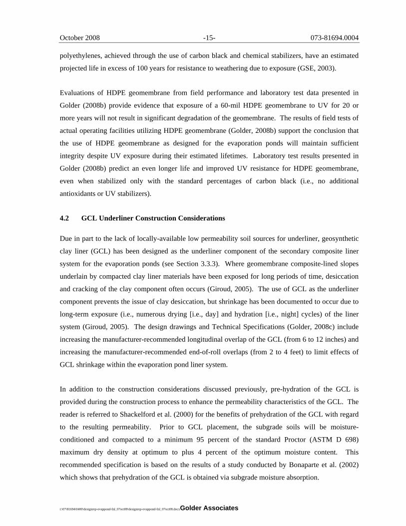
polyethylenes, achieved through the use of carbon black and chemical stabilizers, have an estimated
projected life in excess of 100 years for resistance to weathering due to exposure (GSE, 2003).
Evaluations of HDPE geomembrane from field performance and laboratory test data presented in
Golder (2008b) provide evidence that exposure of a 60-mil HDPE geomembrane to UV for 20 or
more years will not result in significant degradation of the geomembrane. The results of field tests of
actual operating facilities utilizing HDPE geomembrane (Golder, 2008b) support the conclusion that
the use of HDPE geomembrane as designed for the evaporation ponds will maintain sufficient
integrity despite UV exposure during their estimated lifetimes. Laboratory test results presented in
Golder (2008b) predict an even longer life and improved UV resistance for HDPE geomembrane,
even when stabilized only with the standard percentages of carbon black (i.e., no additional
antioxidants or UV stabilizers).
4.2 GCL Underliner Construction Considerations
Due in part to the lack of locally-available low permeability soil sources for underliner, geosynthetic
clay liner (GCL) has been designed as the underliner component of the secondary composite liner
system for the evaporation ponds (see Section 3.3.3). Where geomembrane composite-lined slopes
underlain by compacted clay liner materials have been exposed for long periods of time, desiccation
and cracking of the clay component often occurs (Giroud, 2005). The use of GCL as the underliner
component prevents the issue of clay desiccation, but shrinkage has been documented to occur due to
long-term exposure (i.e., numerous drying [i.e., day] and hydration [i.e., night] cycles) of the liner
system (Giroud, 2005). The design drawings and Technical Specifications (Golder, 2008c) include
increasing the manufacturer-recommended longitudinal overlap of the GCL (from 6 to 12 inches) and
increasing the manufacturer-recommended end-of-roll overlaps (from 2 to 4 feet) to limit effects of
GCL shrinkage within the evaporation pond liner system.
In addition to the construction considerations discussed previously, pre-hydration of the GCL is
provided during the construction process to enhance the permeability characteristics of the GCL. The
reader is referred to Shackelford et al. (2000) for the benefits of prehydration of the GCL with regard
to the resulting permeability. Prior to GCL placement, the subgrade soils will be moisture-
conditioned and compacted to a minimum 95 percent of the standard Proctor (ASTM D 698)
maximum dry density at optimum to plus 4 percent of the optimum moisture content. This
recommended specification is based on the results of a study conducted by Bonaparte et al. (2002)
which shows that prehydration of the GCL is obtained via subgrade moisture absorption.
October 2008 -16- 073-81694.0004
i:\07\81694\0400\designrep-evappond-fnl_07oct08\designrep-evappond-fnl_07oct08.docx Golder Associates
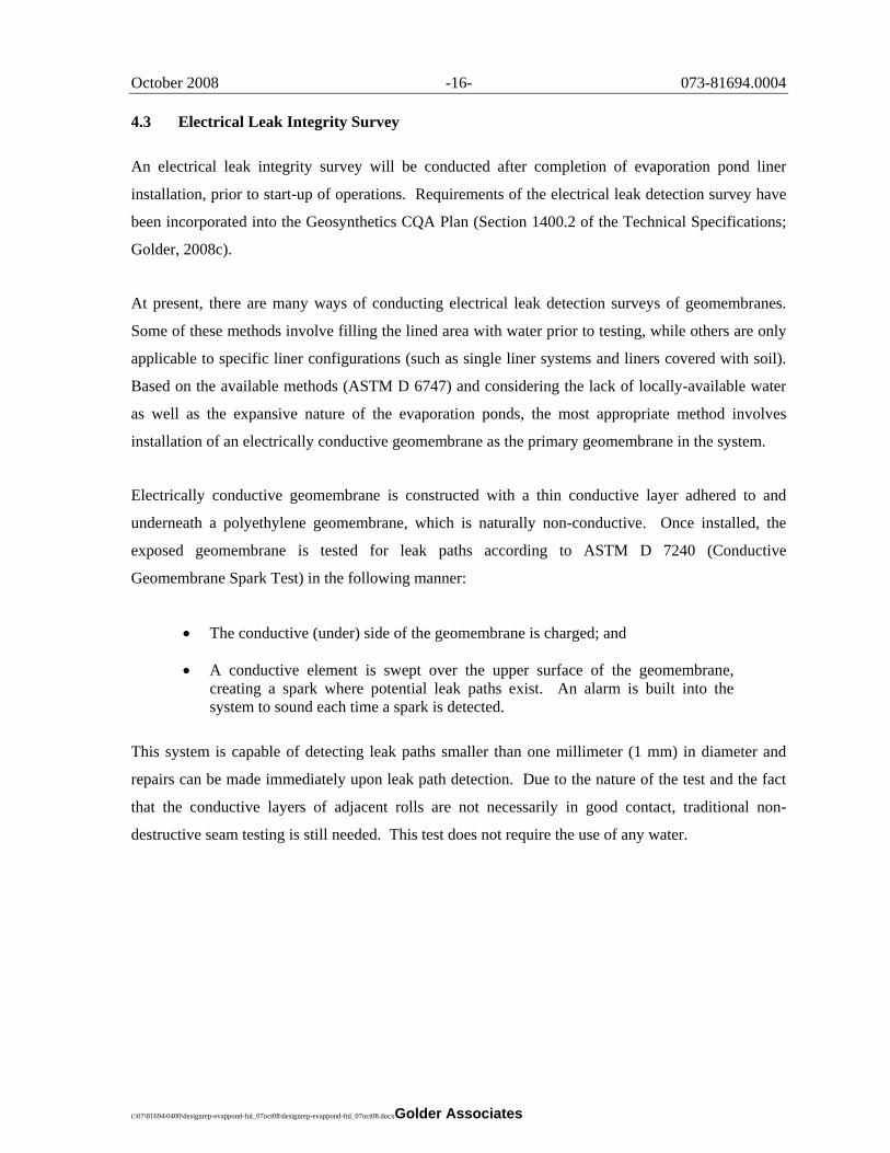
4.3 Electrical Leak Integrity Survey
An electrical leak integrity survey will be conducted after completion of evaporation pond liner
installation, prior to start-up of operations. Requirements of the electrical leak detection survey have
been incorporated into the Geosynthetics CQA Plan (Section 1400.2 of the Technical Specifications;
Golder, 2008c).
At present, there are many ways of conducting electrical leak detection surveys of geomembranes.
Some of these methods involve filling the lined area with water prior to testing, while others are only
applicable to specific liner configurations (such as single liner systems and liners covered with soil).
Based on the available methods (ASTM D 6747) and considering the lack of locally-available water
as well as the expansive nature of the evaporation ponds, the most appropriate method involves
installation of an electrically conductive geomembrane as the primary geomembrane in the system.
Electrically conductive geomembrane is constructed with a thin conductive layer adhered to and
underneath a polyethylene geomembrane, which is naturally non-conductive. Once installed, the
exposed geomembrane is tested for leak paths according to ASTM D 7240 (Conductive
Geomembrane Spark Test) in the following manner:
• The conductive (under) side of the geomembrane is charged; and
• A conductive element is swept over the upper surface of the geomembrane, creating a spark where potential leak paths exist. An alarm is built into the system to sound each time a spark is detected.
This system is capable of detecting leak paths smaller than one millimeter (1 mm) in diameter and
repairs can be made immediately upon leak path detection. Due to the nature of the test and the fact
that the conductive layers of adjacent rolls are not necessarily in good contact, traditional non-
destructive seam testing is still needed. This test does not require the use of any water.

October 2008 -17- 073-81694.0004
i:\07\81694\0400\designrep-evappond-fnl_07oct08\designrep-evappond-fnl_07oct08.docx Golder Associates
5.0 USE OF THIS REPORT
This report has been prepared exclusively for the use of Energy Fuels Resources Corporation (EFRC)
for the specific application to the Piñon Ridge Project. The engineering analyses reported herein
were performed in accordance with accepted engineering practices. No third-party engineer or
consultant shall be entitled to rely on any of the information, conclusions, or opinions contained in
this report without the written approval of Golder and EFRC.
The site investigation reported herein was performed in general accordance with generally accepted
Standard of Care practices for this level of investigation. It should be noted that special risks occur
whenever engineering or related disciplines are applied to identify subsurface conditions. Even a
comprehensive sampling and testing program implemented in accordance with a professional
Standard of Care may fail to detect certain subsurface conditions. As a result, variability in
subsurface conditions should be anticipated and it is recommended that a contingency for
unanticipated conditions be included in budgets and schedules.
Golder sincerely appreciates the opportunity to support EFRC on the Piñon Ridge Project. Please
contact the undersigned with any questions or comments on the information contained in this report.
Respectfully submitted, GOLDER ASSOCIATES INC. Kimberly Finke Morrison, P.E., R.G. James M. Johnson, P.E. Senior Project Manager Principal, Project Director
October 2008 -18- 073-81694.0004
i:\07\81694\0400\designrep-evappond-fnl_07oct08\designrep-evappond-fnl_07oct08.docx Golder Associates
6.0 REFERENCES
6 CCR 1007-1, Part 18 – “State Board of Health Licensing Requirements for Uranium and Thorium Processing”, specifically Appendix A (Criteria relating to the operation of mills and the disposition of the tailings or wastes from these operations).
10 CFR Part 40 – “Domestic Licensing of Source Material”, Appendix A to Part 40 (Criteria Relating to the Operation of Uranium Mills and the Disposition of Tailings or Wastes Produced by the Extraction or Concentration of Source Material from Ores Processed Primarily for their Source Material Content).
40 CFR Part 192 – “Health and Environmental Protection Standards for Uranium and Thorium Mill Tailings”, Subpart D (Standards for management of uranium byproduct materials pursuant to section 84 of the Atomic Energy Act of 1954, as amended).
40 CFR Part 264 – “Standards for Owners and Operators of Hazardous Waste Treatment, Storage, and Disposal Facilities”, Subpart K (Surface Impoundments).
ASTM D 6747. 2004. Standard Guide for Selection of Techniques for Electrical Detection of Potential Leak Paths in Geomembranes.
ASTM D 7240. 2006. Standard Practice for Leak Location using Geomembranes with an Insulating Layer in Intimate Contact with a Conductive Layer via Electrical Capacitance Technique (Conductive Geomembrane Spark Test).
Bonaparte, R., Daniel, D.E., and Koerner, R.M. 2002. “Assessment and Recommendations for Optimal Performance of Waste Containment Systems.” EPA/600/R-02/099, December, U.S. EPA, ORD, Cincinnati, Ohio.
CH2M Hill. 2008. “Piñon Ridge Project, Tailings Stream Analysis (Rev. 2).” Memo issued by Brett Berg. 12 March 2008.
Giroud, J.P. 2005. “Contribution of the Geosynthetics to the Geotechnical Aspects of Waste Containment.” The Mercer Lecture, 2005-2006. Sponsored by Tensar International with the endorsement of the International Society for Soil Mechanics and Geotechnical Engineering and the International Geosynthetics Society (ISSMGE & IGS).
Giroud, J.P., Badu-Tweneboah, K., and Soderman, K.L. 1997. “Comparison of leachate flow through compacted clay liners and geosynthetic clay liners in landfill liner systems.” Geosynthetics International, 4 (3-4), 391-431.
Golder Associates Inc. (Golder). 2007. “Proposed Facility Layout Concepts and Details, Piñon Ridge Plant and Tailings Facilities, Paradox Valley, Colorado.” Submitted to CDPHE. November 7, 2007.
Golder Associates Inc. (Golder). 2008a. “Phase 2 Geotechnical Field and Laboratory Program, Piñon Ridge Project, Montrose County, Colorado.” Report prepared for Energy Fuels Resources Corporation, September 2008.
Golder Associates Inc. (Golder). 2008b. “Resistance of HDPE Geomembrane to Degradation from Ultraviolet (UV) Radiation in Support of Design Work for the Piñon Ridge Project, Montrose County, Colorado.” Letter report prepared for the Colorado Department of Public Health and Environment (CDPHE), 8 August 2008.

October 2008 -19- 073-81694.0004
i:\07\81694\0400\designrep-evappond-fnl_07oct08\designrep-evappond-fnl_07oct08.docx Golder Associates
Golder Associates Inc. (Golder) 2008c. “Technical Specifications, Piñon Ridge Project, Montrose County, Colorado.” Prepared for Energy Fuels Resources Corporation, September 2008.
Golder Associates Inc. (Golder). 2008d. “Tailings Cell Design Report, Piñon Ridge Project, Montrose County, Colorado.” Report prepared for Energy Fuels Resources Corporation, October 2008.
Gundle/SLT Environmental Inc. (GSE). 2003. “Technical Note – HDPE, UV Resistance for GSE Geomembranes.” http://www.truslate.com/grid/techspec.pdf.
Hargreaves, G.L., Hargreaves, G.H., and Riley, J.P. 1985. “Agricultural benefits for Senegal River Basin.” Journal of Irrigation and Drainage Engineering. ASCE 111:113-124.
Kleinfelder. 2007a. “Energy Fuels Resource Corporation, Uranium Mill Licensing Support, Climatological Report, Piñon Ridge Mill Site, Montrose County, Colorado.” 4 December 2007.
Kleinfelder. 2007b. “Climatology Report – Addendum No. 1.” Letter to B. Monok of EFRC and K. Morrison of Golder dated 7 December 2007.
Kleinfelder. 2008. “Design Ground Motions at Piñon Uranium Mill, Colorado.” Draft Memo to K. Morrison, Golder Associates, Inc. 14 January 2008.
Layfield Geosynthetics (Layfield). 2008. “UV Resistance.” http://www.geomembranes.com.
Lupo, J.F., and Morrison, K.F. 2005. “Innovative Geosynthetic Liner Design Approaches and Construction in the Mining Industry.” Geotechnical Special Publication (GSP) 140, Proceedings, Geo-Frontiers 2005, Austin, Texas.
Shackelford, C.D., Benson, C.H., Katsumi, K., Edil, T. and Lin, L. 2000. “Evaluation the Hydraulic Conductivity of GCLs Permeated with Non-Standard Liquids.” Geotextiles and Geomembranes, 18, 133-161.
State of Colorado, Department of Natural Resources, Division of Water Resources, Office of the State Engineer (Office of the State Engineer). 2007. Rules and Regulations for Dam Safety and Dam Construction. January.
U.S. Congress. 1976. Migratory Bird Treaty Act. 16 USC §703 et seq. November.
U.S. Environmental Protection Agency (U.S. EPA). 1992. “Action leakage rates for detection systems (supplemental background document for the final double liners and leak detection systems rule for hazardous waste landfills, waste piles, and surface impoundments).”
Youd, T.L., I.M. Idriss, R.D. Andrus, I. Arango, G. Castro, J.T. Christian, R. Dobry, W.D. Liam Finn, L. F. Harder Jr., M.E. Hynes, K. Ishihara, J. P. Koester, S. S. C. Liao, W. F. Marcuson III, G. R. Martin, J. K. Mitchell, Y. Moriwaki, M. S. Power, P.K. Robertson, R. B. Seed, K. H. Stokoe II. 2001. “Liquefaction Resistance of Soils: Summary Report from the 1996 NCEER and 1998 NCEER/NSF Workshops on Evaluation of Liquefaction Resistance of Soils.” J. Geotechnical and Geoenvironmental Engineering, Vol. 127, No. 10, ASCE.
Zeus Technical Whitepaper (Zeus). 2005. “UV Properties of Plastics: Transmission & Resistance.” http://www.zeusinc.com/pdf/Zeus_UV_Properties.pdf.