Embed Size (px)
Citation preview
Prepared for Hall Equities Group
GEOTECHNICAL INVESTIGATION
SARANAP MIXED-USE DEVELOPMENT
BOULEVARD WAY AND SARANAP AVENUE
CONTRA COSTA COUNTY, CALIFORNIA
UNAUTHORIZED USE OR COPYING OF THIS DOCUMENT IS STRICTLY
PROHIBITED BY ANYONE OTHER THAN THE CLIENT FOR THE SPECIFIC
PROJECT
October 30, 2013 Project No. 12-477
October 30, 2013 Project No. 12-477
Mr. Michael Smith Vice President/Forward Planner Hall Equities Group 1855 Olympic Boulevard, Suite 250 Walnut Creek, California 94596
Subject: Geotechnical Investigation Saranap Mixed-Use Development Boulevard Way and Saranap Avenue Contra Costa County, California Dear Mr. Smith:
We are pleased to present our geotechnical report for the proposed Saranap mixed-use development to be constructed in Contra Costa County, California. Our investigation was performed in accordance with our proposal dated October 26, 2012.
The site is located at the intersection of Boulevard Way and Saranap Avenue. The subject property is comprised of three “sites”, referred to as Sites A, B, and C. Site A is at the northeast corner of Boulevard Way and Saranap Avenue and is currently occupied by a single-family residence, an apartment building, a vacant lot, two commercial buildings and asphalt-paved parking lots. Site B is located at the southeast corner of Boulevard Way and Saranap Avenue. The front portion of Site B is relatively flat and is occupied by an asphalt-paved parking lot and a two-story sanctuary building. The southern end of Site B slopes up gently to the south and is undeveloped. Site C is located at the southwest corner of Boulevard Way and Saranap Avenue. The northeast portion of Site C is occupied by a one-story retail building. The remainder of Site C consists of an asphalt-paved parking lot and landscaped areas.
Plans are to construct a mixed-use development that will include: (1) a seven-story mixed-use building with a basement at Site A, (2) a seven-story mixed-use building where the lower level is below-grade at Site B, and (3) a four-story residential building where the lower level is partially below-grade at Site C. Other project plans include improvements to the existing streets, sidewalks, and/or intersection within the project limits.
Mr. Michael Smith Hall Equities Group October 30, 2013 Page 2 On the basis of our investigation, we conclude the proposed improvements may be constructed as planned, provided the recommendations presented in the attached report are incorporated into the project plans and specifications. The primary geotechnical concerns at the site are: (1) the presence of moderately to highly expansive near-surface clay underlying the site; (2) relatively shallow groundwater for construction of proposed buildings with one basement level; (3) providing adequate foundation support for the proposed buildings; and (4) providing adequate lateral support for adjacent improvements during excavation and construction of basement level.
We conclude the proposed buildings at Sites A and B may be supported on spread footings bearing on native soil or bedrock; provided permanent dewatering system will be installed to reduce hydrostatic pressures on the building slabs and foundations. The proposed building at Site C may be supported on isolated spread footings at interior column locations and continuous, deepened perimeter footings.
The recommendations contained in our report are based on a limited subsurface exploration. Consequently, variations between expected and actual subsurface conditions may be found in localized areas during construction. Therefore, we should be engaged to observe grading and foundation installation during which time we may make changes in our recommendations, if deemed necessary.
We appreciate the opportunity to provide our services to you on this project. If you have any questions, please call.
Sincerely yours, ROCKRIDGE GEOTECHNICAL, INC.
Linda H. J. Liang, P.E., G.E. Craig S. Shields, P.E., G.E. Senior Engineer Principal Geotechnical Engineer
Enclosure
TABLE OF CONTENTS
1.0 INTRODUCTION ...............................................................................................................1
2.0 SCOPE OF WORK ..............................................................................................................2
3.0 FIELD INVESTIGATION AND LABORATORY TESTING ...........................................3 3.1 Test Borings .............................................................................................................3 3.2 Hand-Auger Boring and DPT ..................................................................................4 3.3 Laboratory Testing ...................................................................................................5
4.0 SITE AND SUBSURFACE CONDITIONS .......................................................................5 4.1 Site A .......................................................................................................................5 4.2 Site B ........................................................................................................................6 4.3 Site C ........................................................................................................................7
5.0 SEISMIC CONSIDERATIONS ..........................................................................................7 5.1 Regional Seismicity and Faulting ............................................................................7 5.2 Seismic Hazards .....................................................................................................11
5.2.1 Ground Shaking .........................................................................................11 5.2.2 Fault Rupture .............................................................................................11 5.2.3 Liquefaction and Associated Hazards ........................................................12 5.2.4 Cyclic Densification...................................................................................12
6.0 DISCUSSIONS AND CONCLUSIONS ...........................................................................12 6.1 Foundation Support and Settlement .......................................................................13 6.2 Groundwater ..........................................................................................................14 6.3 Dewatering .............................................................................................................14
6.3.1 Temporary Dewatering ..............................................................................15 6.3.2 Permanent Dewatering ...............................................................................16
6.4 Temporary Cut Slopes and Shoring .......................................................................17
6.5 Soil Corrosivity ......................................................................................................17 6.6 Excavation, Monitoring, and Construction Considerations ...................................18
7.0 RECOMMENDATIONS ...................................................................................................18 7.1 Site Preparation and Grading .................................................................................19
7.1.1 Subgrade Preparation .................................................................................19 7.1.2 Fill Quality and Compaction ......................................................................21 7.1.3 Lime-Treatment .........................................................................................22
7.1.4 Soil Subgrade Stabilization ........................................................................22 7.1.5 Exterior Flatwork Subgrade Preparation ...................................................24 7.1.6 Utility Trench Backfill ...............................................................................25 7.1.7 Geotechnical Services during Grading ......................................................26
7.2 Spread Footings .....................................................................................................26
7.2.1 Buildings at Sites A and B .........................................................................26 7.2.2 Building at Site C .......................................................................................27
7.3 Permanent Dewatering System ..............................................................................28 7.4 Floor Slabs .............................................................................................................29 7.5 Permanent Retaining and Basement Walls ............................................................30 7.6 Temporary Cut Slopes and Shoring .......................................................................31
7.6.1 Cantilevered Soldier Pile and Lagging Shoring System ............................32 7.6.2 Soldier Pile and Lagging Shoring System with Tiebacks ..........................33 7.6.3 Tieback Testing ..........................................................................................34
7.7 Pavement Design ...................................................................................................35
7.7.1 Flexible (Asphalt Concrete) Pavement Design ..........................................35 7.7.2 Rigid (Portland-Cement Concrete) Pavement ...........................................36
7.8 Drainage and Landscaping .....................................................................................37 7.8.1 Bio-retention ..............................................................................................38
7.9 Seismic Design.......................................................................................................39
8.0 GEOTECHNICAL SERVICES DURING CONSTRUCTION ........................................39
9.0 LIMITATIONS ..................................................................................................................39
REFERENCES
FIGURES
APPENDIX A – Boring Logs and DPT Results
APPENDIX B – Laboratory Test Results
LIST OF FIGURES
Figure 1 Site Location Map
Figure 2 Site Plan
Figure 3 Regional Geologic Map
Figure 4 Regional Fault Map
Figure 5 Design Parameters for Soldier-Pile-and-Lagging with Tiebacks Temporary Shoring System
APPENDIX A
Figures A-1 Borings B-1 through B-12 to A-12 Figure A-13 Classification Chart Figure A-14 Physical Properties Criteria for Rock Descriptions Figure A-15 Dynamic Penetrometer Test Results
APPENDIX B
Figure B-1 Plasticity Chart Figures B-2 Particle Size Distribution Reports and B-3 Figures B-4 R-value Test Reports and B-5 Corrosion Test Report
12-477 1 October 30, 2013
GEOTECHNICAL INVESTIGATION
SARANAP MIXED-USE DEVELOPMENT
BOULEVARD WAY AND SARANAP AVENUE
Contra Costa County, California
1.0 INTRODUCTION
This report presents the results of the geotechnical investigation performed by Rockridge
Geotechnical, Inc. for the proposed Saranap mixed-use development to be constructed in Contra
Costa County, California. The site is located at the intersection of Boulevard Way and Saranap
Avenue, as shown on the Site Location Map, Figure 1.
The subject property is comprised of three “sites”, referred to as Sites A, B, and C, as shown on
the Site Plan, Figure 2. Site A is at the northeast corner of Boulevard Way and Saranap Avenue
and is currently occupied by a single-family residence, an apartment building, a vacant lot, and
two commercial buildings and paved parking lots. Site B is located at the southeast corner of
Boulevard Way and Saranap Avenue. The front portion of Site B is relatively flat and is
occupied by an asphalt-paved parking lot and a two-story sanctuary building. The southern end
of Site B slopes up gently to the south and is undeveloped. Site C is located at the southwest
corner of Boulevard Way and Saranap Avenue. The northeast portion of Site C is occupied by a
one-story multi-tenant retail building. The remainder of Site C consists of an asphalt-paved
parking lot and landscaped areas.
Plans are to construct new mixed-use buildings at Sites A, B, and C. The schematic plan for Site
A is to construct a seven-story building with a basement. The basement will be used for parking
and will include deepened parking pits. The first and second levels will consist of parking and
retail space and the upper five levels will consist of dwelling units. At Site B, the plan is to
construct a seven-story building with four levels of wood-frame residential units above three
levels of concrete podium. The lower podium level will be constructed below-grade and the
middle podium level will be partially below-grade. The podium levels will consist of parking
and retail space. At Site C, the plan is to construct a four-story residential building: the first
story will be partially below-grade.
12-477 2 October 30, 2013
Construction of the basements at Sites A, and B will require excavating up to about 20 feet
below the ground surface (bgs); construction of the partial basement at Site C will require
excavating up to about 10 feet bgs. Other project plans include improvements to the existing
streets, sidewalks, and/or intersection within the project limits.
2.0 SCOPE OF WORK
Our investigation was performed in accordance with our proposal dated October 26, 2012. Our
scope of work consisted of exploring the subsurface conditions at Sites A, B, and C and
performing engineering analyses to develop conclusions and recommendations regarding:
soil and groundwater conditions at the site, including a design groundwater level
site seismicity and seismic hazards
the most appropriate foundation type(s) for the proposed buildings
design criteria for the recommended foundation type(s), including vertical and lateral capacities
estimates of foundation settlements
corrosivity of the near-surface soil and the potential effects on buried concrete and metal structures and foundations
site grading and excavation, including criteria for fill quality and compaction
subgrade preparation for interior and exterior concrete slabs-on-grade
temporary cut slopes and shoring
temporary and permanent dewatering
lateral earth pressures for design of permanent retaining and basement walls
pavement design
2013 California Building Code (CBC) site class and design spectral response acceleration parameters
construction considerations.

12-477 3 October 30, 2013
3.0 FIELD INVESTIGATION AND LABORATORY TESTING
Our field investigation consisted of drilling 11 test borings, advancing one hand-auger boring,
and performing a dynamic penetrometer test (DPT). Details of our field investigation are
presented in this section.
3.1 Test Borings
Prior to drilling the test borings, we obtained drilling permits from the Contra Costa County
Environmental Health Division (CCCEHD) and contacted Underground Service Alert (USA) to
notify them of our work, as required by law. We also retained Precision Locating, LLC, a
private utility locator, to check that the boring locations were clear of buried utilities.
On May 9, 10, and 13, 2013, 11 test borings, designated B-1 through B-8 and B-10 through B-12
were drilled by Exploration Geoservices of San Jose, California, using a truck-mounted drill rig
equipped with six-inch-diameter hollow-stem augers at the approximate locations shown on
Figure 2. These borings were drilled to depths between 24 and 25 feet bgs. During drilling, our
field engineer logged the soil and rock encountered and obtained representative samples for
visual classification and laboratory testing. The logs of the test borings are presented on Figures
A-1 through A-8 and A-10 through A-12 in Appendix A. The soil and rock encountered in the
borings were classified in accordance with the descriptions shown on Figures A-13 and A-14.
Soil samples were obtained using the following samplers:
Sprague and Henwood (S&H) split-barrel sampler with a 3.0-inch outside diameter and 2.5-inch inside diameter, lined with 2.43-inch inside diameter brass/or stainless steel tubes.
Standard Penetration Test (SPT) split-barrel sampler with a 2.0-inch outside and 1.5-inch inside diameter, without liners.
The samplers were driven with a 140-pound, downhole, wireline hammer falling about 30 inches
per drop. The samplers were driven up to 18 inches and the hammer blows required to drive the
samplers were recorded every six inches and are presented on the boring logs. A “blow count” is
12-477 4 October 30, 2013
defined as the number of hammer blows per six inches of penetration or 50 blows for six inches
or less of penetration. The blow counts required to drive the S&H and SPT samplers were
converted to approximate SPT N-values using factors of 0.6 and 1.0, respectively, to account for
sampler type and approximate hammer energy. The blow counts used for this conversion were:
(1) the last two blow counts if the sampler was driven more than 12 inches, (2) the last one blow
count if the sampler was driven more than six inches but less than 12 inches, and (3) the only
blow count if the sampler was driven six inches or less. The converted SPT N-values are
presented on the boring logs.
Upon completion of drilling, the boreholes were backfilled with cement grout under the
observation of the CCCEHD inspector. The pavement at the borehole locations was patched
with asphalt. The soil cuttings generated by the borings were placed in landscape areas at the
site.
3.2 Hand-Auger Boring and DPT
Boring B-9 was located in a landscaped area behind the existing sanctuary building at Site B and
was not accessible by a truck-mounted drill rig. Therefore, we advanced a hand-auger boring at
this location on May 13, 2013 to a depth of 4 feet bgs to obtain soil samples for visual
classification. The approximate location for Boring B-9 is shown on Figure 2. The log of
Boring B-9 is shown on Figure A-9 in Appendix A.
On May 13, 2013, we also performed a DPT, designated DPT-1, adjacent to Boring B-9 to
investigate the in-situ strength of the underlying soil. The DPT was performed by driving a 1.4-
inch-diameter, cone-tipped probe into the ground with a 35-pound hammer falling about 15
inches. The blows required to drive the probe were recorded at 10-centimeter intervals and
converted to SPT N-values for use in our engineering analyses. The DPT was advanced to
practical refusal, defined as more than 50 blows to advance the probe 10 centimeters, at a depth
of approximately 15 feet bgs. The DPT results are presented on Figure A-15 in Appendix A.
12-477 5 October 30, 2013
3.3 Laboratory Testing
We re-examined the soil samples obtained from our borings to confirm the field classifications
and select representative samples for laboratory testing. Soil samples were tested to measure
moisture content, dry density, Atterberg limits, gradation, resistance value (R-value), and
corrosivity. The results of the laboratory tests are presented on the boring logs and in Appendix
B.
4.0 SITE AND SUBSURFACE CONDITIONS
A regional geologic map of the area (Figure 3) indicates the site is underlain by sediments (QTs)
overlying sedimentary rocks (Tms). Site and subsurface conditions for Sites A, B, and C are
described below.
4.1 Site A
Site A is located at the northeast corner of Boulevard Way and Saranap Avenue and
encompasses an area of 65,674 square feet. Site A slopes gently up to the north with ground
surface elevations varying from Elevation 214 to 228 feet1. Site A is currently occupied by a
single-family residence, an apartment building, a vacant lot, and two commercial buildings and
paved parking lots. At Borings B-1 and B-2, the pavement section consists of 1 to 2 inches of
asphalt concrete and 5 to 6 inches of aggregate base.
Borings B-1 through B-5 drilled in Site A indicate it is underlain by 8 to 22 feet of sediments
consisting of interbedded layers of stiff to hard clay with variable amounts of sand and gravel,
and medium dense to dense sand and gravel with variable amounts of clay. Atterberg limits tests
performed on the near-surface clay obtained from Borings B-1 and B-4 indicate the clay is
highly expansive2. The sediments are underlain by sedimentary rocks consisting of siltstones
and mudstones that are soft to low hardness, plastic to friable in strength, and deeply weathered.
1 Elevations referenced in this report are based on Alta/ACSM Land Title Survey for the project dated
June, 2012 and prepared by Kier & Wright Civil Engineers & Surveyors, Inc. 2 Expansive soil undergoes volume changes with changes in moisture content.
12-477 6 October 30, 2013
Approximate elevations of the top of bedrock encountered at boring locations are shown on
Figure 2.
Groundwater was encountered at a depth of 15 feet bgs (Elevation 202 feet) in Boring B-1 during
drilling. Groundwater was not encountered during drilling in Borings B-2, B-3, B-4, and B-5.
The borehole for Boring B-3 was left open overnight before grouting and groundwater was
measured at a depth of 9 feet bgs (Elevation 210 feet) in the borehole the next morning.
4.2 Site B
Site B is located at the southeast corner of Boulevard Way and Saranap Avenue. Site B is
comprised of two parcels encompassing a total area of 57,546 square feet. The front (north)
portion of Site B is relatively flat with the ground surface at approximately Elevation 215 feet,
and is occupied by an asphalt-paved parking lot and a two-story sanctuary building. The
southern end of Site B slopes up gently to the south with ground surface elevations varying from
Elevations 215 to 230 feet, and is undeveloped.
Borings B-6, B-7, and B-9 and DPT-1 performed at the front (north) portion of Site B indicate it
is underlain by 12 to 15 feet of sediments overlying sedimentary rock. Boring B-8, located at the
south end of Site B encountered sediments to the maximum depth explored of 24.5 feet bgs.
Where explored, sediments consist of interbedded layers of stiff to hard clay with variable
amounts of sand, and medium dense to very dense sand and gravel with variable amounts of clay
and silt. Atterberg limits performed on the near-surface clay obtained from Boring B-7 indicate
the clay has a low expansion potential. Sedimentary rocks encountered consist of mudstone and
claystone that are soft to low hardness, plastic to friable strength, and deeply weathered.
Groundwater was not encountered in Borings B-6 and B-9 and DPT-1 during drilling.
Groundwater was encountered in Boring B-7 at 13 feet bgs (Elevation 199.5 feet) and Boring B-
8 at 17.5 feet bgs (Elevation 204.5 feet) during drilling.
12-477 7 October 30, 2013
4.3 Site C
Site C is located at the southwest corner of Boulevard Way and Saranap Avenue. Site C is
comprised of four parcels encompassing an area of 25,640 square feet. The northeast portion of
the site is occupied by a one-story multi-tenant retail building. The remainder of the site is
occupied by an asphalt-paved parking lot and landscaped areas. The ground surface at Site C
varies from Elevations 225 feet at the north to about 232 feet at the south.
Borings B-10, B-11, and B-12 performed at Site C indicate it is underlain by sediments to depths
of 21 feet bgs at Boring B-10 and to the maximum depths explored of 25 feet at Borings B-11
and B-12. The sediments consist of interbedded layers of stiff to very stiff clay with variable
amounts of sand, and medium dense to dense sand with variable amounts of clay. Atterberg
limits performed on the near-surface clay obtained from Boring B-11 indicate the clay is
moderately to highly non-expansive. Bedrock encountered near the bottom of Boring B-10
consists of claystone that is soft to low hardness, plastic to friable strength, and deeply
weathered.
Groundwater was encountered in Boring B-10 at a depth of 18.5 feet bgs (Elevation 208.5 feet)
at the end of drilling, and at a depth of 20.3 feet bgs (Elevation 206.5 feet) 2-1/2 hours later, just
prior to grouting. Groundwater was not encountered in Borings B-11 and B-12 during drilling.
5.0 SEISMIC CONSIDERATIONS
5.1 Regional Seismicity and Faulting
The site is located in the Coast Ranges geomorphic province that is characterized by northwest-
southeast trending valleys and ridges. These are controlled by folds and faults that resulted from
the collision of the Farallon and North American plates and subsequent shearing along the San
Andreas fault system. Movements along this plate boundary in the Northern California region
occur along right-lateral strike-slip faults of the San Andreas Fault system.
12-477 8 October 30, 2013
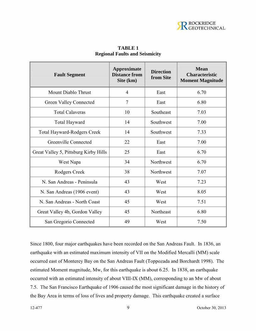
The major active faults in the area are the Calaveras, Hayward, San Andreas, and Green Valley
and Mount Diablo faults. These and other faults in the region are shown on Figure 4. For these
and other active faults within a 50-kilometer radius of the site, the distance from the site and
estimated mean characteristic Moment magnitude3 [2007 Working Group on California
Earthquake Probabilities (WGCEP) (USGS 2008) and Cao et al. (2003)] are summarized in
Table 1.
3 Moment magnitude is an energy-based scale and provides a physically meaningful measure of the
size of a faulting event. Moment magnitude is directly related to average slip and fault rupture area.
12-477 9 October 30, 2013
TABLE 1
Regional Faults and Seismicity
Fault Segment
Approximate
Distance from
Site (km)
Direction
from Site
Mean
Characteristic
Moment Magnitude
Mount Diablo Thrust 4 East 6.70
Green Valley Connected 7 East 6.80
Total Calaveras 10 Southeast 7.03
Total Hayward 14 Southwest 7.00
Total Hayward-Rodgers Creek 14 Southwest 7.33
Greenville Connected 22 East 7.00
Great Valley 5, Pittsburg Kirby Hills 25 East 6.70
West Napa 34 Northwest 6.70
Rodgers Creek 38 Northwest 7.07
N. San Andreas - Peninsula 43 West 7.23
N. San Andreas (1906 event) 43 West 8.05
N. San Andreas - North Coast 45 West 7.51
Great Valley 4b, Gordon Valley 45 Northeast 6.80
San Gregorio Connected 49 West 7.50
Since 1800, four major earthquakes have been recorded on the San Andreas Fault. In 1836, an
earthquake with an estimated maximum intensity of VII on the Modified Mercalli (MM) scale
occurred east of Monterey Bay on the San Andreas Fault (Toppozada and Borchardt 1998). The
estimated Moment magnitude, Mw, for this earthquake is about 6.25. In 1838, an earthquake
occurred with an estimated intensity of about VIII-IX (MM), corresponding to an Mw of about
7.5. The San Francisco Earthquake of 1906 caused the most significant damage in the history of
the Bay Area in terms of loss of lives and property damage. This earthquake created a surface
12-477 10 October 30, 2013
rupture along the San Andreas Fault from Shelter Cove to San Juan Bautista approximately 470
kilometers in length. It had a maximum intensity of XI (MM), an Mw of about 7.9, and was felt
560 kilometers away in Oregon, Nevada, and Los Angeles. The most recent earthquake to affect
the Bay Area was the Loma Prieta Earthquake of 17 October 1989 with an Mw of 6.9. This
earthquake occurred in the Santa Cruz Mountains approximately 97 kilometers southwest of the
site.
In 1868, an earthquake with an estimated maximum intensity of X on the MM scale occurred on
the southern segment (between San Leandro and Fremont) of the Hayward Fault. The estimated
Mw for the earthquake is 7.0. In 1861, an earthquake of unknown magnitude (probably an Mw
of about 6.5) was reported on the Calaveras Fault. The most recent significant earthquake on this
fault was the 1984 Morgan Hill earthquake (Mw = 6.2).
The U.S. Geological Survey’s (USGS) 2007 WGCEP has compiled the earthquake fault research
for the San Francisco Bay area in order to estimate the probability of fault segment rupture.
They have determined that the overall probability of moment magnitude 6.7 or greater
earthquake occurring in the San Francisco Bay Region during the next thirty years is 63 percent.
The highest probabilities are assigned to the Hayward/Rodgers Creek Fault and the northern
segment of the San Andreas Fault: these probabilities are 31 and 21 percent, respectively (USGS
2008). The probabilities assigned to Calaveras, Concord-Green Valley, and Mount Diablo
Thrust faults are 7, 3, and 1 percent, respectively (USGS 2008).
12-477 11 October 30, 2013
5.2 Seismic Hazards
During a major earthquake on a segment of one of the nearby faults, strong to very strong ground
shaking is expected to occur at the project site. Strong shaking during an earthquake can result
in ground failure such as that associated with soil liquefaction4, lateral spreading5, and cyclic
densification6. The results of our evaluation regarding seismic considerations for the project site
are presented in the following sections.
5.2.1 Ground Shaking
The seismicity of the site is governed by the activity of the Mount Diablo Thrust, Green Valley,
and Calaveras faults, although ground shaking from future earthquakes on other faults, including
the Hayward and San Andreas faults, will also be felt at the site. The intensity of earthquake
ground motion at the site will depend upon the characteristics of the generating fault, distance to
the earthquake epicenter, and magnitude and duration of the earthquake. We judge that strong to
very strong ground shaking could occur at the site during a large earthquake on one of the nearby
faults.
5.2.2 Fault Rupture
Historically, ground surface displacements closely follow the trace of geologically young faults.
The site is not within an Earthquake Fault Zone, as defined by the Alquist-Priolo Earthquake
Fault Zoning Act, and no known active or potentially active faults exist on the site. We therefore
conclude the risk of fault offset at the site from a known active fault is very low. In a seismically
active area, the remote possibility exists for future faulting in areas where no faults previously
4 Liquefaction is a phenomenon where loose, saturated, cohesionless soil experiences temporary
reduction in strength during cyclic loading such as that produced by earthquakes. 5 Lateral spreading is a phenomenon in which surficial soil displaces along a shear zone that has
formed within an underlying liquefied layer. Upon reaching mobilization, the surficial blocks are transported downslope or in the direction of a free face by earthquake and gravitational forces.
6 Cyclic densification, also referred to as differential compaction, is a phenomenon in which non-saturated, cohesionless soil is compacted by earthquake vibrations, causing ground-surface settlement.
12-477 12 October 30, 2013
existed; however, we conclude the risk of surface faulting and consequent secondary ground
failure from previously unknown faults is also very low.
5.2.3 Liquefaction and Associated Hazards
When a saturated, cohesionless soil liquefies, it experiences a temporary loss of shear strength
created by a transient rise in excess pore pressure generated by strong ground motion. Soil
susceptible to liquefaction includes loose to medium dense sand and gravel, low-plasticity silt,
and some low-plasticity clay deposits. Flow failure, lateral spreading, differential settlement,
loss of bearing strength, ground fissures and sand boils are evidence of excess pore pressure
generation and liquefaction.
The site is generally underlain by stiff clay and interbedded clayey sand and clayey gravel layers
which are not susceptible to liquefaction because of their cohesion and/or density. Therefore, we
conclude the potential for liquefaction to occur at the site is very low.
5.2.4 Cyclic Densification
Cyclic densification (also referred to as differential compaction) of non-saturated sand (sand
above groundwater table) can occur during an earthquake, resulting in settlement of the ground
surface and overlying improvements. The soil encountered above the ground water table is not
susceptible to cyclic densification because of it cohesion and/or density. Therefore, we conclude
the potential for cyclic densification to occur at the site is very low.
6.0 DISCUSSIONS AND CONCLUSIONS
From a geotechnical standpoint, we conclude the site can be developed as planned, provided the
recommendations presented in this report are incorporated into the project plans and
specifications and implemented during construction. The primary geotechnical concerns
associated with the proposed project are: (1) the presence of moderately to highly expansive
near-surface clay underlying the site; (2) relatively shallow groundwater for construction of
proposed buildings with basement levels; (3) providing adequate foundation support for the
12-477 13 October 30, 2013
proposed buildings; and (4) providing adequate lateral support for adjacent improvements during
excavation and construction of basement levels. These and other geotechnical issues as they
pertain to the proposed development are discussed in this section.
6.1 Foundation Support and Settlement
The moderately to highly expansive near-surface clay at the site is subject to volume changes
during seasonal fluctuations in moisture content. These volume changes can cause cracking of
foundations and floor slabs. Therefore, foundation and slabs should be designed and constructed
to resist the effects of the expansive clay. These effects can be mitigated by moisture
conditioning the expansive clay, providing non-expansive soil below interior and exterior slabs,
and supporting foundations below the zone of severe moisture change.
The proposed buildings at Sites A and B will have a basement and the finished floor for these
buildings will be located below the potential zone of moisture change. Therefore, there should
be no volumetric changes in the soil and mitigation of the expansion potential of the soil is not
required for proposed buildings at Sites A and B. We anticipate the foundation level of proposed
buildings with a basement will be underlain by relatively strong sediments or bedrock that can
support moderate building loads. Therefore, we conclude proposed buildings at Sites A and B
can be supported on conventional spread footings.
The proposed building at Site C will be at-grade along Boulevard Way (western property line)
and partially below-grade at the eastern portion of the site. We anticipate the proposed building
at Site C will be underlain by relatively strong sediments that can support moderate building
loads. We conclude the proposed building at Site C may be supported on individual spread
footings at interior column locations and continuous, deepened perimeter footings. The
perimeter footings should be deepened (see Section 7.2.2) to act as a barrier to reduce the
potential for moisture change beneath the slab-on-grade floors.
12-477 14 October 30, 2013
We estimate total and differential settlement of properly constructed spread footings designed
using the recommendations presented in Section 7.2 of this report will be less than 1 inch and 1/2
inch over a 30-foot horizontal distance, respectively.
6.2 Groundwater
As discussed in Section 4.0, groundwater was encountered in Borings B-1, B-3, B-7, B-8, B-10,
and B-12 during drilling and/or prior to grouting at depths between 9 and 20.3 feet bgs (between
Elevations 199.5 and 210 feet). Groundwater was not observed in the other borings during
drilling. Because of the relatively low permeability of the clay and bedrock at these depths, the
groundwater levels encountered in the borings are not necessarily the stabilized groundwater
level.
Based on our experience with projects on sloping terrain and relatively shallow bedrock similar
to the subject site, groundwater may be encountered where it has been trapped by impervious
soil/rock or is flowing through pervious zones in the underlying bedrock. The presence of
groundwater at the site will vary depending on localized subsurface conditions, the presence of
damaged utility lines, rainfall amounts and other seasonal conditions, and irrigation practices.
Based on the results of this investigation, we recommend proposed buildings at Sites A, B, and C
be designed using design groundwater depths of 8 feet bgs, 10 feet bgs, and 15 feet bgs,
respectively.
6.3 Dewatering
Because of the relatively high groundwater table and the anticipated depth of excavation,
temporary dewatering will likely be required during construction of basement levels at Sites A
and B. Based on our experience, we believe that providing an underslab drainage system to
reduce hydrostatic pressures will result in a more economic foundation design than a fully
waterproofed building restrained with hydrostatic uplift anchors.
12-477 15 October 30, 2013
6.3.1 Temporary Dewatering
Based on our experience on projects situated at sites with sloping terrain and shallow bedrock
similar to the subject site, some seepage of groundwater into the basement excavations should be
expected, especially if the excavations are open during wet weather conditions. In most cases,
we anticipate groundwater seepage, if any, would have a relatively low flow rate. However,
there may be bedrock underlying the site that may be highly permeable at some locations;
particularly where groundwater can flow through poorly cemented sandstone and siltstone
deposits or in fractures in the bedrock. Flow of groundwater into the excavation during
construction could result in sloughing, slumping, or caving of the sides of the excavation and/or
wet, difficult working conditions. Therefore, we anticipate it will be necessary to temporarily
dewater excavations during construction.
Temporary dewatering is typically performed by installing a series of wells around the perimeter
of the building, with interior wells also used for larger footprints. However, based on our
investigation, we conclude the effectiveness of temporary dewatering wells will be limited at the
site due to the relatively low permeability of bedrock encountered at the site. Therefore, we
believe a passive system, in which water is collected from the perimeter of the site using gravel-
filled trenches, will be more appropriate. Subdrains will also likely be required across the base
of the excavation to provide a firm, relatively dry base from which to construct the foundation
system.
The flow of water in the bedrock is controlled by the number, size, and connectivity of fractures.
Therefore, the flow may be too large for a passive system in localized portions of the site,
particularly where large fractures or poorly cemented sandstone are encountered. If these
conditions are encountered, it may be necessary to install a limited number of dewatering wells
behind the excavation, or to install trench drains and drum sumps in front of the temporary
shoring system.
12-477 16 October 30, 2013
The dewatering system should be designed and installed by an experienced contractor.
Groundwater removed during dewatering should be disposed of in accordance with applicable
state and local regulations.
Typically, dewatering can induce settlement of adjacent structures and improvements when the
water level is lowered around the perimeter of the site. However, because the site is generally
underlain by interbedded deposits of stiff clays and dense sands and gravels overlying bedrock,
we conclude the potential for dewatering-induced ground settlement is low.
6.3.2 Permanent Dewatering
We believe permanent dewatering to reduce hydrostatic pressures may result in a more
economical foundation design than a fully waterproofed building with uplift anchors to resist
hydrostatic uplift forces for buildings at Sites A and B. The permanent dewatering system
should consist of an at least 12-inch-thick layer of Class 2 permeable material containing parallel
collection pipes spaced approximately every 20 feet, center-to-center. The collection pipes
should consist of four-inch-diameter, Schedule 40, perforated PVC pipes. The collection pipes
should be connected to at least one sump pit. The groundwater seeping beneath the building
should be continuously collected in the sump and then pumped into the storm drain or sanitary
sewer system for appropriate discharge.
In addition to the underslab drainage system, wall backdrains should be installed along the
perimeter walls to reduce the hydrostatic pressures acting on walls and to reduce the amount of
water collected by the underslab drain. The wall backdrains may be connected to the underslab
drain system.
The design of the permanent dewatering system should consider the possibility that a portion of
the drain may fail, resulting in an unwanted build-up of hydrostatic pressures which could
damage he foundation or basement walls. Inspection and maintenance programs should be
implemented to verify that the system is performing as expected during the life of the structure.
These programs should ensure that replacement parts, including pumps, are readily available in
case of mechanical failure. In addition, it may be desirable to install “pop-off” valves in the
12-477 17 October 30, 2013
garage floor slab to allow water to drain into the garage in case hydrostatic pressure build up
beneath the floor slab.
6.4 Temporary Cut Slopes and Shoring
Excavations that will be deeper than five feet and will be entered by workers should be sloped or
shored in accordance with CAL-OSHA standards (29 CFR Part 1926). The shoring engineer
should be responsible for shoring design. The contractor should be responsible for the
construction and safety of temporary slopes.
We anticipate excavations for proposed buildings at Sites A, B, and C will extend to depths up to
about 20, 20, and 10 feet bgs, respectively. Where space permits, the sides of the temporary
excavation can be sloped. Where space does not permit sloping of the excavation perimeter,
temporary shoring systems will be required to support the sides of the proposed excavations. We
judge that a cantilevered soldier pile and lagging shoring system is appropriate for support of
excavations that are less than 12 feet deep. Where the excavation depth exceeds 12 feet, a
cantilevered system may be uneconomical and tiebacks may be required. Where it is not feasible
to install tiebacks, then internal bracing of the excavation will be required.
6.5 Soil Corrosivity
Corrosivity testing was performed by Sunland Analytical of Rancho Cordova, California on soil
samples obtained from Borings B-4 and B-11 at depths of 1.5 and 2 feet bgs, respectively. The
results of the corrosivity tests are presented in Appendix B of this report. The resistivity test
results indicate the near-surface soil is at the site highly corrosive to buried steel. Accordingly,
buried iron, steel, cast iron, galvanized steel, and dielectric-coated steel or iron should be
properly protected against corrosion. The chloride ion concentrations and pH of the soil samples
are determined to be mildly to moderately corrosive to buried metallic and concrete structures.
The sulfide and sulfate ion concentrations of the soil do not present corrosion problems for
buried iron, steel, mortar-coated steel and reinforced concrete structures.
12-477 18 October 30, 2013
6.6 Excavation, Monitoring, and Construction Considerations
Some excavation of bedrock may be required for construction of proposed basements. The
bedrock is soft to low hardness and deeply weathered near the surface and grades harder and less
weathered with depth. We anticipate the weathered rock within the proposed excavation can be
excavated with conventional grading equipment (excavators and bull dozers). However, because
the bedrock was only investigated in widely spaced borings during our investigation, it is
possible that harder rock and difficult drilling or excavation may be encountered in other parts of
the site. Therefore, the contractors involved in shoring installation and excavation for basements
should be prepared to excavate hard rock, including the possible use of hydraulic breaking
equipment, and should bid the project accordingly.
The contractor should establish survey points on the shoring and on adjacent buildings and
streets within 30 feet of the excavation perimeter prior to the start of excavation. These survey
points should be used to monitor the vertical and horizontal movements of the shoring and
surrounding structures and streets during construction. The contractor should also survey and
take photographs of any adjacent buildings prior to the start of excavation and immediately after
its completion.
During excavation, the shoring system may deform laterally, which could cause the ground
surface adjacent to the shoring wall to settle. The magnitudes of shoring movements and the
resulting settlements are difficult to estimate because they depend on many factors, including the
method of installation and the contractor's skill in the shoring installation. Ground movements
due to a properly designed and constructed shoring system should be within ordinary accepted
limits of about one inch. A monitoring program should be established to evaluate the effects of
the excavation on the adjacent buildings and surrounding ground.
7.0 RECOMMENDATIONS
Our recommendations for site preparation and grading, design of foundations and basement
walls, temporary cut slopes and shoring, permanent dewatering, and other geotechnical aspects
of the project are presented in this section.

12-477 19 October 30, 2013
7.1 Site Preparation and Grading
In areas to receive improvements (including buildings, pavements, and exterior concrete slabs),
site preparation should include stripping existing vegetation and the upper soil containing over
three percent organic matter. Site demolition should include the removal of existing pavements,
underground utilities, and foundations. In general, abandoned underground utilities should be
removed to the property line or service connections and properly capped or plugged with
concrete. Where existing utility lines are outside of the proposed building footprint and will not
interfere with the proposed construction, they may be abandoned in-place as allowed by utility
company. Voids resulting from demolition activities should be properly backfilled with
compacted fill following the recommendations provided later in this section.
Demolished asphalt concrete should be taken to an asphalt recycling facility. The aggregate base
underlying the asphalt pavement may be reused as select fill, provided it meets the requirements
presented in Section 7.1.2.
7.1.1 Subgrade Preparation
To mitigate the detrimental effects of expansive near-surface clay, slabs-on-grade constructed at-
grade or less than three feet bgs should be underlain by at least 12 inches (measured below the
bottom of capillary moisture break) of non-expansive soil consisting of select fill or lime-treated
onsite soil. Where the upper 12 inches of the at-grade building pad subgrade consists of low-
plasticity soil, replacement with select fill or lime-treatment will not be required. The non-
expansive soil should extend at least five feet beyond the perimeter of the proposed buildings
where concrete flatwork or pavements will be constructed, except where constrained by the
property line. The subgrade for proposed concrete flatwork and pavers should also be
overexcavated to accommodate at least 12 inches of non-expansive soil.
Where the finished floor will be located below a depth of three feet bgs, the floor slab will be
located below the potential zone of moisture change. Therefore, there should be no volumetric
changes in the soil and mitigation of the expansion potential of the soil is not required beneath
floor slabs founded at least three feet bgs.
12-477 20 October 30, 2013
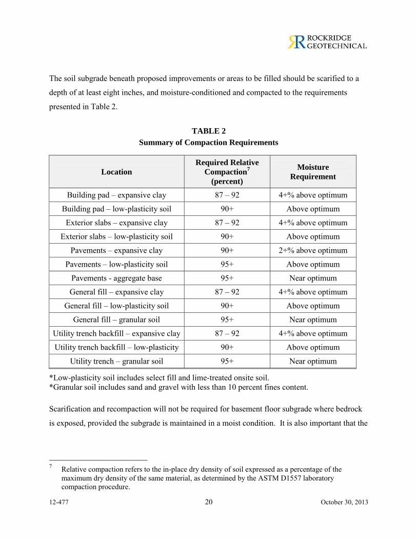
The soil subgrade beneath proposed improvements or areas to be filled should be scarified to a
depth of at least eight inches, and moisture-conditioned and compacted to the requirements
presented in Table 2.
TABLE 2
Summary of Compaction Requirements
Location
Required Relative
Compaction7
(percent)
Moisture
Requirement
Building pad – expansive clay 87 – 92 4+% above optimum
Building pad – low-plasticity soil 90+ Above optimum
Exterior slabs – expansive clay 87 – 92 4+% above optimum
Exterior slabs – low-plasticity soil 90+ Above optimum
Pavements – expansive clay 90+ 2+% above optimum
Pavements – low-plasticity soil 95+ Above optimum
Pavements - aggregate base 95+ Near optimum
General fill – expansive clay 87 – 92 4+% above optimum
General fill – low-plasticity soil 90+ Above optimum
General fill – granular soil 95+ Near optimum
Utility trench backfill – expansive clay 87 – 92 4+% above optimum
Utility trench backfill – low-plasticity 90+ Above optimum
Utility trench – granular soil 95+ Near optimum
*Low-plasticity soil includes select fill and lime-treated onsite soil. *Granular soil includes sand and gravel with less than 10 percent fines content.
Scarification and recompaction will not be required for basement floor subgrade where bedrock
is exposed, provided the subgrade is maintained in a moist condition. It is also important that the
7 Relative compaction refers to the in-place dry density of soil expressed as a percentage of the
maximum dry density of the same material, as determined by the ASTM D1557 laboratory compaction procedure.
12-477 21 October 30, 2013
moisture content of soil subgrade is sufficiently high to reduce the expansion potential. If the
grading work is performed during the dry season, moisture-conditioning will be required.
If grading work is performed during the rainy season, the contractor may find the subgrade
material too wet to compact to the recommended relative compaction and will have to be
scarified and aerated to lower its moisture content so the specified compaction can be achieved.
Material to be dried by aeration should be scarified to a depth of at least 12 inches; the scarified
soil should be turned at least twice a day to promote uniform drying. Once the moisture content
of the aerated soil has been reduced to acceptable levels, the soil should be compacted in
accordance with our recommendations. Aeration typically is the least costly method used to
stabilize the subgrade soil; however, it generally requires the most time to complete. Other soil
stabilization alternatives include overexcavating and placing drier material, and lime-treatment.
Recommendations for various subgrade stabilization options are presented below in Section
7.1.4.
If soft or poorly cemented sedimentary rock is encountered at the base of the excavation, the
subgrade should be cut with a smooth bucket and hand-cleaned. Moist or wet siltstone,
mudstone, or claystone bedrock may be susceptible to softening or disturbance by construction
vehicles, particularly if there is standing water on the subgrade. If extensive portions of the
subgrade are saturated at the time of grading, the subgrade may be disturbed. If the subgrade is
disturbed, the soft, disturbed material should be overexcavated to expose firm material. The
overexcavated areas should be backfilled with compacted aggregate base.
7.1.2 Fill Quality and Compaction
On-site soil may be used as general fill, provided the material is free of organic matter, contain
no rocks or lumps larger than three inches in greatest dimension, and be approved by the
Geotechnical Engineer. Select fill should consist of on-site or imported soil that is free of
organic matter, contains no rocks or lumps larger than four inches in greatest dimension, has a
liquid limit of less than 40 and a plasticity index lower than 12, and is approved by the
Geotechnical Engineer. Samples of proposed fill material should be submitted to the

12-477 22 October 30, 2013
Geotechnical Engineer at least three business days prior to use at the site. The grading contractor
should provide analytical test results or other suitable environmental documentation indicating
the imported fill is free of hazardous materials at least three days before use at the site. If this
data is not available, up to two weeks should be allowed to perform analytical testing on the
proposed imported material. Fill should be placed in horizontal lifts not exceeding eight inches
in uncompacted thickness, and moisture-conditioned and compacted to the requirements
presented in Table 2.
7.1.3 Lime-Treatment
If the non-expansive soil to be placed beneath the at-grade building pads and exterior concrete
flatwork and pavement is to consist of lime-treated on-site soil, the upper 12 inches of the soil
subgrade should be treated in place with about four percent dolomitic quicklime by dry weight of
soil. The dry weight of soil should be assumed to be 110 pounds per cubic foot (pcf) for
calculating lime quantities. A specialty subcontractor should perform the lime treatment. Prior
to lime treatment, we recommend the site be graded to a level pad elevation in accordance with
our previous recommendations and all below-grade obstructions removed. The soil treated with
lime should be mixed and compacted in one lift. The lime should be thoroughly blended with
the soil and allowed to set for 24 hours prior to remixing and compaction. The lime-treated soil
should be moisture-conditioned to above optimum moisture content and compacted to at least 90
percent relative compaction.
It should be noted that disposal of lime-treated soil is typically expensive because of the high pH
of the treated soil. In addition, lime-treated soil should be completely removed from landscaping
areas.
7.1.4 Soil Subgrade Stabilization
In some areas, soft, wet soil may be exposed during grading, causing the subgrade to deflect and
rut under the weight of grading equipment. Although, the majority of the soil beneath the site
consists of stiff to hard clay, if heavy wheeled equipment is used close to the water table, these
12-477 23 October 30, 2013
materials may become disturbed and soften. In these areas, some form of subgrade stabilization
may be required. Several options for stabilizing subgrade are presented below.
Aeration
Aeration consists of mixing and turning the soil to naturally lower the moisture content to an
acceptable level. Aeration typically requires several days to a week of warm, dry weather to
effectively dry the material. Material to be dried by aeration should be scarified to a depth of at
least 12 inches; the scarified material should be turned at least twice a day to promote uniform
drying. Once the moisture content of the aerated soil has been reduced to acceptable levels, the
soil should be compacted in accordance with our previous recommendations. Aeration is
typically the least costly subgrade stabilization alternative; however, it generally requires the
most time to complete and may not be effective if the soft material extends to great depths.
Aeration will likely not be effective where the podium subgrade extends below or near the
groundwater table; however, it depends on the time of year construction is performed.
Overexcavation
Another method of achieving suitable subgrade in areas where soft, wet soil is exposed is to
overexcavate the soft subgrade soil and replace it with drier, granular material. If the soft
material extends to great depths, the upper 18 to 24 inches of soft material may be overexcavated
and a geotextile tensile fabric (Mirafi 500X or equivalent) placed beneath the granular backfill to
help span over the weaker material. The fabric should be pulled tight and placed at the base of
the overexcavation, extending at least two feet laterally beyond the limits of the overexcavation
in all directions. The fabric should be overlapped by at least two feet at all seams. Granular
material such as Class 2 aggregate base should then be placed and compacted over the geotextile
tensile fabric.
Where very soft subgrade conditions are encountered, a bi-directional geogrid, such as Tensar
TriAx TX-140 or equivalent, may be required in lieu of tensile fabric. Where geogrids are used
the depth of overexcavation will likely be on the order of 12 to 18 inches. The geogrids should
be overlapped by at least two feet and tied with hog rings or nylon ties at a spacing not to exceed
12-477 24 October 30, 2013
10 feet. The geogrids should be covered with a well-graded granular fill such as Class 2
aggregate base; open-graded rock should not be used. All backfill placed over the geogrid
should be compacted in accordance with our previous recommendations.
Chemical Treatment
Lime and/or cement have been successfully used to dry and stabilize fine-grained soils with
varying degrees of success. Lime- and/or cement-treatment will generally decrease soil density,
change its plasticity properties, and increase its strength. The degree to which lime will react
with soil depends on such variables as type of soil, mineralogy, quantity of lime, and length of
time the lime-soil mixture is cured. Cement is generally used when a significant amount of
granular material or low-plasticity silt is present in the soil. The quantity of lime and/or cement
added generally ranges from 3 to 7 percent by weight and should be determined by laboratory
testing. The specialty contractor performing the chemical treatment should select the most
appropriate additive and quantity for the soil conditions encountered.
If chemical treatment is used to stabilize soft subgrade, a treatment depth of about 18 inches
below the final soil subgrade will likely be required. The soil being treated should be scarified
and thoroughly broken up to full depth and width. The treated soil should not contain rocks or
soil clods larger than three inches in greatest dimension. Treated soil should be compacted to at
least 90 percent relative compaction, and at least 95 percent relative compaction in the upper six
inches of vehicular pavement subgrade.
7.1.5 Exterior Flatwork Subgrade Preparation
We recommend exterior concrete flatwork, including patio slabs, pavers, and sidewalks, be
underlain by at least 12 inches of non-expansive soil consisting of on-site low-plasticity soil,
select fill, or lime-treated on-site soil. Even with 12 inches of non-expansive soil, exterior slabs
may experience some cracking due to shrinking and swelling of the underlying expansive soil.
Thickening the slab edges and adding additional reinforcement will control this cracking to some
degree. In addition, where slabs provide access to buildings, it would be prudent to dowel the
12-477 25 October 30, 2013
entrance to the building to permit rotation of the slab as the exterior ground shrinks and swells
and to prevent a vertical offset at the entries.
7.1.6 Utility Trench Backfill
Excavations for utility trenches can be readily made with a backhoe. All trenches should
conform to the current CAL-OSHA requirements. To provide uniform support, pipes or conduits
should be bedded on a minimum of four inches of sand or fine gravel. After the pipes and
conduits are tested, inspected (if required) and approved, they should be covered to a depth of six
inches with sand or fine gravel, which should be mechanically tamped. The pipe bedding and
cover should be eliminated where an impermeable plug is required as described below. Backfill
for utility trenches and other excavations is also considered fill, and should be placed and
compacted as according to the recommendations previously presented. If imported clean sand or
gravel (defined as soil with less than 10 percent fines) is used as backfill, it should be compacted
to at least 95 percent relative compaction. Jetting of trench backfill should not be permitted.
Special care should be taken when backfilling utility trenches in pavement areas. Poor
compaction may cause excessive settlements, resulting in damage to the pavement section.
Foundations for the proposed building should be bottomed below an imaginary line extending up
at a 1.5:1 (horizontal to vertical) inclination from the base of utility trenches. Alternatively, the
portion of the utility trench (excluding bedding) that is below the 1.5:1 line can be backfilled
with controlled low-strength material (CLSM) with a 28-day unconfined compressive strength of
at least 100 pounds per square inch (psi).
Where utility trenches enter at-grade building pads, an impermeable plug consisting of CLSM, at
least three feet in length, should be installed where the trenches enter the building footprint.
Furthermore, where sand- or gravel-backfilled trenches cross planter areas and pass below
asphalt or concrete pavements, a similar plug should be placed at the edge of the pavement. The
purpose of these recommendations is to reduce the potential for water to become trapped in
trenches beneath the building or pavements. This trapped water can cause heaving of soils
beneath slabs and softening of subgrade soil beneath pavements.
12-477 26 October 30, 2013
7.1.7 Geotechnical Services during Grading
All grading and site development plans should be reviewed by the Geotechnical Engineer to
verify that they conform to the intent of our recommendations. The Geotechnical Engineer
should be present and onsite to observe demolition and related fill placement, site grading,
subgrade preparation, and fill and subdrain placement. In addition, the Geotechnical Engineer
should perform nuclear field density tests to check the moisture content and relative compaction
of soil subgrade, engineered fill, and utility trench backfill. These observations and tests will
allow us to compare actual with anticipated soil conditions and to check that the contractor’s
work conforms to the geotechnical aspects of the plans and specifications. If any variations or
undesirable conditions are encountered during construction, we should be notified so that
additional recommendations can be made.
7.2 Spread Footings
7.2.1 Buildings at Sites A and B
The proposed buildings at Sites A and B will have basements and may be supported on
continuous and/or individual spread footings bearing on firm native soil or bedrock. Footings
should be bottomed at least 12 inches below the adjacent interior soil subgrade (measured from
the base of the underslab drain rock. Continuous footings should be at least 18 inches wide and
isolated spread footings should be at least 24 inches wide. We recommend footings founded on
firm native soil be designed using allowable bearing pressures of 4,000 pounds per square foot
(psf) for dead-plus-live loads and 5,300 psf for total design loads, which include wind or seismic
forces; these values include factors of safety of at least 2.0 and 1.5, respectively. Footings
founded on bedrock may be designed using allowable bearing pressures of 10,000 psf for dead-
plus-live loads and 13,000 psf for total design loads, which include wind or seismic forces; these
values include factors of safety of at least 2.0 and 1.5, respectively. The approximate elevations
of the top of bedrock encountered at boring locations are shown on Figure 2.
Lateral loads may be resisted by a combination of passive pressure on the vertical faces of the
footings and friction between the bottoms of the footings and the supporting soil/bedrock. To
12-477 27 October 30, 2013
compute lateral resistance for footings excavated into soil, we recommend using an equivalent
fluid weight of 270 pounds per cubic foot (pcf); and frictional resistance should be computed
using a base friction coefficient of 0.35. To compute lateral resistance for footings excavated
into bedrock, we recommend using an equivalent fluid weight of 500 pcf; and frictional
resistance should be computed using a base friction coefficient of 0.5. The upper foot of
soil/bedrock should be ignored for passive resistance unless confined by a slab or pavement. The
passive pressure and frictional resistance values include a factor of safety of at least 1.5 and may
be used in combination without reduction.
Footing excavations should be free of standing water, debris, and disturbed materials prior to
placing concrete. The bottoms and sides of the footing excavations should be moistened
following excavation and maintained in a moist condition until concrete is placed. If the
foundation soil dries during construction, the footing will eventually heave, which may result in
cracking and distress. Where water infiltration is encountered during footing excavations, we
recommend protecting the footing subgrades from softening due to water infiltration by placing a
two-inch-thick mud slab at the bottom of the excavations immediately after they are excavated.
We should check footing excavations prior to placement of reinforcing steel and concrete.
7.2.2 Building at Site C
We recommend the proposed building at Site C be supported on individual spread footings at
interior column locations and continuous, deepened perimeter footings. Continuous footings
should be at least 18 inches wide and isolated spread footings should be at least 24 inches wide.
Perimeter footings should be bottomed at least 36 inches below the lowest adjacent outside
grade. The perimeter footing embedment depth may be decreased by six inches where pavement
or concrete flatwork is adjacent to the building. Interior footings should extend at least 24 inches
below the bottom of the capillary moisture break. Spread footings for proposed at-grade
buildings should bear on firm native soil and may be designed using allowable bearing pressures
of 4,000 psf for dead-plus-live loads and 5,300 psf for total design loads, which include wind or
seismic forces.
12-477 28 October 30, 2013
Lateral loads may be resisted by a combination of passive pressure on the vertical faces of the
footings and friction between the bottoms of the footings and the supporting soil. To compute
lateral resistance, we recommend using an equivalent fluid weight of 270 pcf; the upper foot of
soil should be ignored unless confined by a slab or pavement. Frictional resistance should be
computed using a base friction coefficient of 0.35. The passive pressure and frictional resistance
values include a factor of safety of at least 1.5 and may be used in combination without
reduction.
Footing excavations should be free of standing water, debris, and disturbed materials prior to
placing concrete. The bottoms and sides of the footing excavations should be moistened
following excavation and maintained in a moist condition until concrete is placed. If the
foundation soil dries during construction, the footing will eventually heave, which may result in
cracking and distress. We should check footing excavations prior to placement of reinforcing
steel and concrete.
7.3 Permanent Dewatering System
For proposed buildings at Sites A and B, a permanent dewatering system will be required
beneath the basement slab-on-grade floors to prevent hydrostatic uplift pressure on the slabs.
We recommend the permanent dewatering system consist of an at least 12-inch-thick layer of
Class 2 permeable material containing parallel collection pipes spaced approximately every 20
feet, center-to-center. The Class 2 permeable material should meet the requirements of Caltrans
Standard Specifications 68-1.025 most recent edition. The collection pipes should consist of
four-inch-diameter, Schedule 40, perforated PVC pipe (perforations down). The pipes should be
installed such that they are surrounded on all sides by at least four inches of permeable material.
The pipes should drain at a gradient of at least one percent to at least one sump pit location in the
garage level. If manifold pipes are required to collect the water from individual collector pipes,
they should consist of solid PVC pipes of appropriate diameter to collect the required volume of
water. The sump system should be designed to discharge water directly to the storm drain
system without allowing the water to build up beneath the slab-on-grade floor.
12-477 29 October 30, 2013
7.4 Floor Slabs
Where water vapor transmission through the floor slab is undesirable, we recommend installing a
water vapor retarder beneath the floor. A vapor retarder is generally not required beneath
parking garage floor slabs because there is sufficient air circulation to allow evaporation of
moisture that is transmitted through the slab; however, we recommend the vapor retarder be
installed below the slab-on-grade in utility rooms and any areas in or adjacent to the parking
garage that will be used for storage and/or will receive a floor covering or coating.
A capillary moisture break consists of at least four inches of clean, free-draining gravel or
crushed rock. The vapor retarders for Sites A and B should meet the requirements for Class A
and the vapor retarder for Site C should meet the requirements for Class B vapor retarders stated
in ASTM E1745., The vapor retarder should be placed in accordance with the requirements of
ASTM E1643. These requirements include overlapping seams by six inches, taping seams, and
sealing penetrations in the vapor retarder. If required by the structural engineer, the vapor
retarder may be covered with two inches of sand to aid in curing the concrete and to protect the
vapor retarder during slab construction. The sand overlying the vapor retarder should be moist at
the time concrete is placed. However, excess water trapped in the sand could eventually be
transmitted as vapor through the slab. Therefore, if rain is forecast prior to pouring the slab, the
sand should be covered with plastic sheeting to avoid wetting. If the sand becomes wet, concrete
should not be placed until the sand has been dried or replaced.
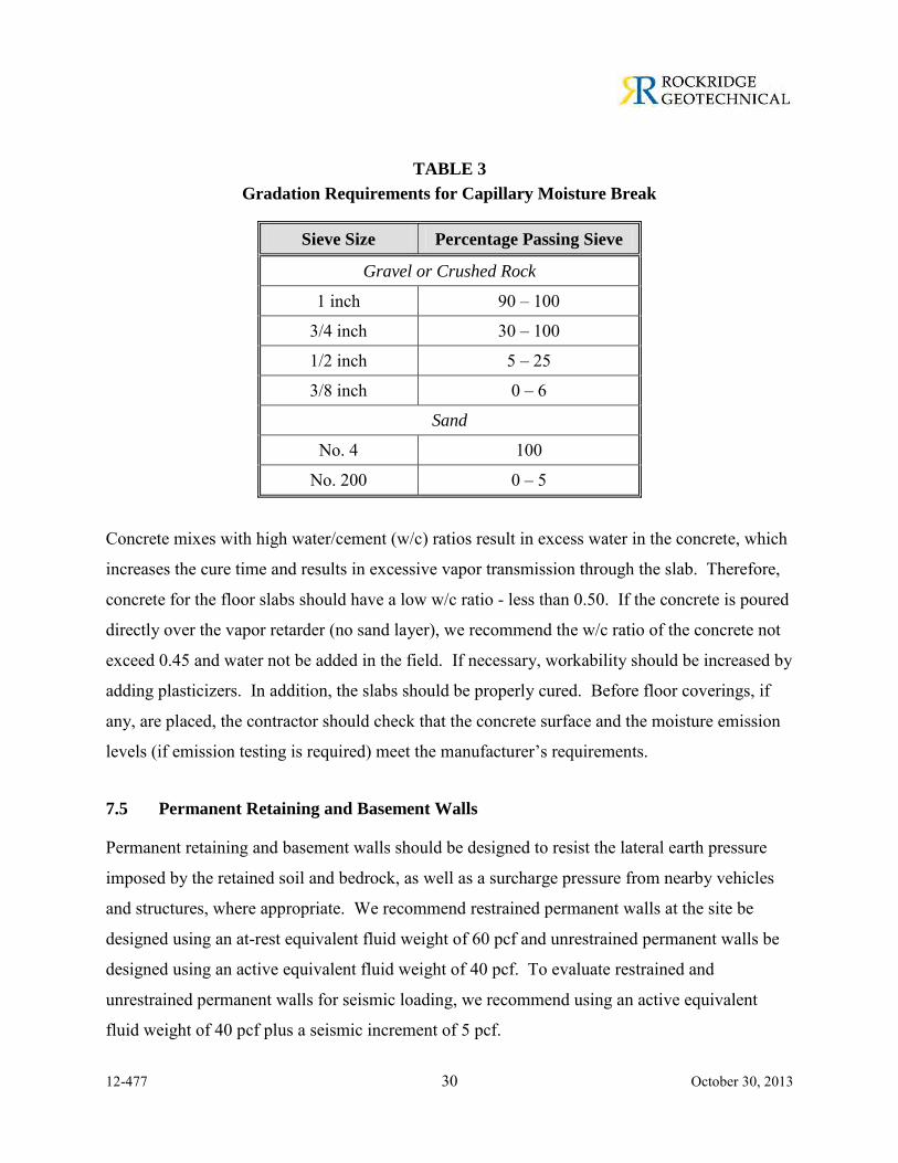
The particle size of the capillary break material and sand (if used) should meet the gradation
requirements presented in Table 3.
12-477 30 October 30, 2013
TABLE 3
Gradation Requirements for Capillary Moisture Break
Sieve Size Percentage Passing Sieve
Gravel or Crushed Rock
1 inch 90 – 100
3/4 inch 30 – 100
1/2 inch 5 – 25
3/8 inch 0 – 6
Sand
No. 4 100
No. 200 0 – 5
Concrete mixes with high water/cement (w/c) ratios result in excess water in the concrete, which
increases the cure time and results in excessive vapor transmission through the slab. Therefore,
concrete for the floor slabs should have a low w/c ratio - less than 0.50. If the concrete is poured
directly over the vapor retarder (no sand layer), we recommend the w/c ratio of the concrete not
exceed 0.45 and water not be added in the field. If necessary, workability should be increased by
adding plasticizers. In addition, the slabs should be properly cured. Before floor coverings, if
any, are placed, the contractor should check that the concrete surface and the moisture emission
levels (if emission testing is required) meet the manufacturer’s requirements.
7.5 Permanent Retaining and Basement Walls
Permanent retaining and basement walls should be designed to resist the lateral earth pressure
imposed by the retained soil and bedrock, as well as a surcharge pressure from nearby vehicles
and structures, where appropriate. We recommend restrained permanent walls at the site be
designed using an at-rest equivalent fluid weight of 60 pcf and unrestrained permanent walls be
designed using an active equivalent fluid weight of 40 pcf. To evaluate restrained and
unrestrained permanent walls for seismic loading, we recommend using an active equivalent
fluid weight of 40 pcf plus a seismic increment of 5 pcf.
12-477 31 October 30, 2013
Where traffic loads are expected within 10 feet of the walls, an additional design load of 100 psf
should be applied to the upper ten feet of the wall. Where neighboring and existing foundations
are supported above a “zone-of-influence” line extending up from the bottom of a permanent
wall at an inclination of 1.5:1 (horizontal: vertical), the wall should be designed for a surcharge
pressure. We can provide the surcharge pressure once the dimensions and depth of the
neighboring foundations are known.
The design pressure recommended above is based on fully drained walls. One acceptable
method for backdraining a wall is to place a prefabricated drainage panel against the back of the
wall. The drainage panel should extend down to a perforated PVC collector pipe at the base of
the wall. The pipe should be surrounded on all sides by at least four inches of Caltrans Class 2
permeable material or 3/4-inch drain rock wrapped in filter fabric (Mirafi NC or equivalent).
AdvanEdge pipe or equivalent may be used in lieu of the pipe and permeable material. The pipe
should be sloped to drain to a sump or another suitable outlet.
To protect against moisture migration, below-grade basement walls should be waterproofed and
water stops should be placed at all construction joints. In recent years, we have observed
numerous leaks in below-grade portions of buildings constructed with waterproofed, shotcrete
walls. In areas where there is a high sensitivity to leaks, we recommend cast-in-place concrete
be considered.
If backfill is required behind walls, the walls should be braced, or hand compaction equipment
used, to prevent unacceptable surcharges on walls (as determined by the structural engineer).
7.6 Temporary Cut Slopes and Shoring
The safety of workers and equipment in or near the excavation is the responsibility of the
contractor. The selection, design, construction, and performance of the shoring system should be
the responsibility of the contractor. A structural engineer knowledgeable in this type of
construction should design the shoring. We should review the geotechnical aspects of the
proposed shoring system to ensure that it meets our requirements. During construction, we
12-477 32 October 30, 2013
should observe the installation of the shoring system and check the condition of the soil
encountered during excavation.
We judge that temporary cuts which are less than 15 feet high, above groundwater, and inclined
no steeper than 1.5:1 (horizontal:vertical) in sediments and 3/4:1 in weathered rock, will be
stable provided that they are not surcharged by equipment or building material. Temporary
shoring will be required where temporary slopes are not possible because of space constraints.
A structural/civil engineer knowledgeable in soldier-pile-and-lagging temporary shoring systems
should be retained to design the shoring. The shoring designer should design the shoring system
for lateral deformation of less than one inch at any location on the shoring. We should review
the final shoring plans and calculations to check that they are consistent with the
recommendations presented in this report.
7.6.1 Cantilevered Soldier Pile and Lagging Shoring System
We recommend a cantilevered soldier pile-and-lagging shoring system be designed to resist an
active equivalent fluid weight of 40 pcf. In locations where minimizing lateral deflections is
critical, such as near adjacent buildings or near sensitive underground utilities, the shoring
system should be designed to resist an at-rest equivalent fluid weight of 60 pcf, plus any
foundation surcharge loads. Where traffic loads are expected within 10 feet of the shoring walls,
an additional design load of 100 psf should be applied to the upper ten feet of the wall. Where
construction equipment will be working behind the walls within a horizontal distance equal to
the wall height, the design should include a surcharge pressure of 250 psf. The above pressures
should be assumed to act over the entire width of the lagging installed above the excavation. The
active pressure need only be assumed to act over one pile width below the bottom of the
excavation.
Passive resistance at the toe of the soldier pile should be computed using an equivalent fluid
weights of 270 and 500 pcf in soil and bedrock, respectively, with a maximum passive earth
pressure of 2,500 psf and 4,000 psf in soil and bedrock, respectively. The upper foot of soil
should be ignored when computing passive resistance. Passive pressure can be assumed to act
12-477 33 October 30, 2013
over an area of three soldier pile widths assuming the toe of the soldier pile is filled with
structural concrete. If lean concrete is placed in the soldier pile shaft, the passive pressure can be
assumed to act over two pile diameters. These passive pressure values include a factor of safety
of at least 1.5.
Soldier piles should be placed in pre-drilled holes backfilled with concrete. Where granular
layers are present below the groundwater, installation of the soldier piles may require casing or
use of drilling slurry to reduce caving of the holes. Installing soldier piles by driving or using
vibratory methods is acceptable, but should not be permitted within 25 feet of existing structures.
7.6.2 Soldier Pile and Lagging Shoring System with Tiebacks
Recommended lateral pressures for the design of soldier pile and lagging shoring with tiebacks
are presented on Figure 5. Where it is not feasible to install tiebacks, then internal bracing of the
excavation will be required. Internal bracing should be preloaded to limit movement of the
shoring. The penetration of the soldier piles must be sufficient to ensure stability and resist the
downward loading of tiebacks.
Passive resistance at the toe of the soldier piles should be computed using an equivalent fluid
weights of 270 and 500 pcf in soil and bedrock, respectively, with a maximum passive earth
pressure of 2,500 psf and 4,000 psf in soil and bedrock, respectively. These values include
factors of safety of at least 1.5. Passive pressure can be assumed to act over an area of three
soldier pile widths provided the toe of the soldier pile hole is filled with structural concrete. The
upper foot of soil should be ignored when computing passive resistance. Recommendations for
the installation of soldier piles and lagging are presented in the previous Section 7.6.1.
Vertical loads can be resisted by skin friction along the portion of the soldier piles below the
excavation. We recommend using an allowable skin friction value of 1,000 psf to compute the
required soldier pile embedment. End bearing should be neglected.
Design criteria for tiebacks are also presented on Figure 5. As shown, tiebacks should derive
their load-bearing capacity from the soil behind an imaginary line sloping upward from a point
12-477 34 October 30, 2013
H/5 feet away from the bottom of the excavation at an angle of 60 degrees from horizontal,
where H is the wall height in feet. The minimum stressing lengths for strand and bar tendons
should be 15 and 10 feet, respectively. The minimum bond length for strand and bar tendons
should both be 15 feet.
Allowable capacities of the tiebacks will depend upon the drilling method, hole diameter, grout
pressure, and workmanship. The shoring contractor should be prepared to use smooth-cased
method (such as a Klemm rig) to install the tiebacks where caving soil is encountered.
The shoring designer should be responsible for determining the actual length of tieback required.
The determination should be based on the designer’s familiarity with the installation method to
be used.
7.6.3 Tieback Testing
The computed bond length of tiebacks should be confirmed by a performance- and proof-testing
program under the observation of our field engineer. The first two production tiebacks and two
percent of the remaining tiebacks should be performance tested to 1.5 times the design load. The
remaining tiebacks should be confirmed by a proof test to 1.25 times the design load. The
movement of each tieback should be monitored with a free-standing, tripod-mounted dial gauge
during performance and proof testing. The bottom of excavation should not extend more than
two feet below a row of unsecured tiebacks.
The performance test is used to verify the capacity and the load-deformation behavior of the
tiebacks. It is also used to separate and identify the causes of tieback movement, and to check
that the designed unbonded length has been established. In the performance test, the load is
applied to the tieback in several cycles of incremental loading and unloading. During the test,
the tieback load and movement are measured. The maximum test load should be held for a
minimum of 10 minutes, with readings taken at 0, 1, 3, 6, and 10 minutes. If the difference
between the 1- and 10-minute readings is less than 0.04 inch during the loading, the test is
discontinued. If the difference is more than 0.04 inch, the holding period is extended by 50
12-477 35 October 30, 2013
minutes to 60 minutes, and the movements should be recorded at 15, 20, 25, 30, 45, and 60
minutes.
A proof test is a simple test used to measure the total movement of the tieback during one cycle
of incremental loading. The maximum test load should be held for a minimum of 10 minutes,
with readings taken at 0, 1, 2, 3, 6, and 10 minutes. If the difference between the 1- and 10-
minute reading is less than 0.04 inch, the test is discontinued. If the difference is more than 0.04
inch, the holding period is extended by 50 minutes to 60 minutes, and the movements should be
recorded at 15, 20, 25, 30, 45, and 60 minutes.
We should evaluate the tieback test results and determine whether the tiebacks are acceptable. A
performance- or proof-tested tieback with a ten-minute hold is acceptable if the tieback carries
the maximum test load with less than 0.04 inch movement between 1 and 10 minutes, and total
movement at the maximum test load exceeds 80 percent of the theoretical elastic elongation of
the unbonded length.
A performance- or proof-tested tieback with a 60-minute hold is acceptable if the tieback carries
the maximum test load with less than 0.08 inch movement between 6 and 60 minutes, and total
movement at the maximum test load exceeds 80 percent of the theoretical elastic elongation of
the unbonded length. Tiebacks that failed to meet the first criterion will be assigned a reduced
capacity.
7.7 Pavement Design
Design recommendations for asphalt concrete and Portland cement concrete pavements and
concrete pavers are presented in the following sections.
7.7.1 Flexible (Asphalt Concrete) Pavement Design
The State of California flexible pavement design method was used to develop the recommended
asphalt concrete (AC) pavement sections. Resistance value (R-value) tests performed on near-
surface soil samples collected from Borings B-1 and B-10 indicate the material has R-values of 2
and 4, respectively. For AC pavement design, we selected a minimum recommended R-value of
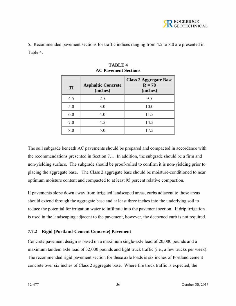
12-477 36 October 30, 2013
5. Recommended pavement sections for traffic indices ranging from 4.5 to 8.0 are presented in
Table 4.
TABLE 4
AC Pavement Sections
TI
Asphaltic Concrete
(inches)
Class 2 Aggregate Base
R = 78
(inches)
4.5 2.5 9.5
5.0 3.0 10.0
6.0 4.0 11.5
7.0 4.5 14.5
8.0 5.0 17.5 The soil subgrade beneath AC pavements should be prepared and compacted in accordance with
the recommendations presented in Section 7.1. In addition, the subgrade should be a firm and
non-yielding surface. The subgrade should be proof-rolled to confirm it is non-yielding prior to
placing the aggregate base. The Class 2 aggregate base should be moisture-conditioned to near
optimum moisture content and compacted to at least 95 percent relative compaction.
If pavements slope down away from irrigated landscaped areas, curbs adjacent to those areas
should extend through the aggregate base and at least three inches into the underlying soil to
reduce the potential for irrigation water to infiltrate into the pavement section. If drip irrigation
is used in the landscaping adjacent to the pavement, however, the deepened curb is not required.
7.7.2 Rigid (Portland-Cement Concrete) Pavement
Concrete pavement design is based on a maximum single-axle load of 20,000 pounds and a
maximum tandem axle load of 32,000 pounds and light truck traffic (i.e., a few trucks per week).
The recommended rigid pavement section for these axle loads is six inches of Portland cement
concrete over six inches of Class 2 aggregate base. Where fire truck traffic is expected, the
12-477 37 October 30, 2013
pavement section should consist of 6-1/2 inches of Portland cement concrete over six inches of
Class 2 aggregate base.
The modulus of rupture of the concrete should be at least 500 psi at 28 days. Contraction joints
should be constructed at 15-foot spacing. Where the outer edge of a concrete pavement meets
asphalt concrete pavement, the concrete slab should be thickened by 50 percent at a taper not to
exceed a slope of 1 in 10. For areas that will receive weekly garbage truck traffic, we
recommend the slab be reinforced with a minimum of No. 4 bars at 16-inch spacing in both
directions. Recommendations for subgrade preparation and aggregate base compaction for
concrete pavement are the same as those described above for AC pavement.
7.8 Drainage and Landscaping
Positive surface drainage should be provided around the buildings to direct surface water away
from the foundations. To reduce the potential for water ponding adjacent to the buildings, we
recommend the ground surface within a horizontal distance of five feet from the building slope
down away from the building with a surface gradient of at least two percent in unpaved areas and
one percent in paved areas. In addition, roof downspouts should be discharged into controlled
drainage facilities to keep the water away from the foundations. The use of water-intensive
landscaping around the perimeter of at-grade buildings should be avoided to reduce the amount
of water introduced to the expansive clay subgrade.
Prior experience and industry literature indicate that some species of high water-demand8 trees
can induce ground-surface settlement by drawing water from the expansive clay, causing it to
shrink. Where these types of trees are planted near buildings, the ground-surface settlement may
result in damage to structure. This problem usually occurs 10 or more years after planting, as the
trees reach mature height. To reduce the risk of tree-induced, building settlement, we
recommend trees of the following genera are not planted within 25 feet of the proposed building:
Eucalyptus, Populus, Quercus, Crataegus, Salix, Sorbus (simple-leafed), Ulmus, Cupressus,
8 “Water-demand” refers to the ability of the tree to withdraw large amounts of water from the soil
subgrade, rather than soil suction exerted by the root system.
12-477 38 October 30, 2013
Chamaecyparis, and Cupressocyparis. Because this is a limited list and does not include all
genera that may induce ground-surface settlement, a tree specialist should be consulted prior to
selection of trees to be planted at the site.
Care should be taken to minimize the potential for subsurface water to collect beneath pavements
and pedestrian walkways. Where landscape beds and tree wells are immediately adjacent to
pavements and flatwork that are not designed as permeable systems, we recommend vertical
cutoff barriers be incorporated into the design to prevent irrigation water from saturating the
subgrade and aggregate base. These barriers may consist of either flexible impermeable
membranes or deepened concrete curbs.
7.8.1 Bio-retention
We anticipate proposed bio-retention areas, if any, at the site will be constructed on
predominantly clayey soil. The rate of infiltration for the clayey soil that will underlie the
majority of the proposed bio-retention areas is expected to be very low; and the near-surface clay
at the site is moderately to highly expansive. The primary concerns with the proposed bio-
retention areas are: (1) providing suitable support for foundations and curbs constructed near the
bio-retention areas, and (2) potential for subsurface water from the bio-retention areas to migrate
(and possibly build up) beneath pavements and the proposed buildings. Therefore, we
recommend the following for design of bioswales:
We recommend bio-retention areas constructed at the site should be provided with underdrains and/or drain inlets because of the low permeability of the near-surface soil.
Bio-retentions areas should be constructed no closer than 5 feet from the new buildings and pavements.
The sides of bio-retention areas should be sloped 1:1 (horizontal:vertical).
Where a vertical curb or foundation is constructed near a bio-retention area, the curb and the edge of the foundation should be founded below an imaginary line extending up at an inclination of 1.5:1 (horizontal: vertical) from the base of the bio-retention area.
Subdrain pipes should be placed at the base of bio-retention areas. The subdrain pipes should be installed 8 inches above the bottom of the infiltration area for treatment areas that are at least 5 feet away from the new buildings and pavements. The intent of this
12-477 39 October 30, 2013
recommendation is to allow infiltration into the underlying soil, but to reduce the potential for bio-retention areas to flood during periods of heavy rainfall.
Where the proposed bio-retention areas will be located less than 5 feet from the new buildings
and pavements due to space constraints, a 4-inch-diameter perforated subdrain pipe should be
placed 4 inches above the base of the treatment area. The intent is to allow infiltration into the
underlying soil, but to reduce potential for groundwater build-up in the treatment area.
7.9 Seismic Design
For design in accordance with the 2013 CBC, we recommend Site Class C be used for the site.
The latitude and longitude of the site are 37.89319 and -122.07771, respectively. Hence, in
accordance with the 2013 CBC, we recommend the following:
SS = 1.849g, S1 = 0.603g
SMS = 1.849g, SM1 = 0.784g
SDS = 1.233g, SD1 = 0.523g
PGAM = 0.692g
Seismic Design Category D for Risk Categories I, II and III.
8.0 GEOTECHNICAL SERVICES DURING CONSTRUCTION
Prior to construction, Rockridge Geotechnical should review the project plans and specifications
to verify that they conform to the intent of our recommendations. During construction, our field
engineer should provide on-site observation and testing during site preparation, placement and
compaction of fill, and installation of temporary shoring and building foundations. These
observations will allow us to compare actual with anticipated soil conditions and to verify that
the contractor's work conforms to the geotechnical aspects of the plans and specifications.
9.0 LIMITATIONS
This geotechnical study has been conducted in accordance with the standard of care commonly
used as state-of-practice in the profession. No other warranties are either expressed or implied.

12-477 40 October 30, 2013
The recommendations made in this report are based on the assumption that the subsurface
conditions do not deviate appreciably from those disclosed in the exploratory borings. If any
variations or undesirable conditions are encountered during construction, we should be notified
so that additional recommendations can be made. The foundation recommendations presented in
this report are developed exclusively for the proposed development described in this report and
are not valid for other locations and construction in the project vicinity.
REFERENCES
Cao, T., Bryant, W. A., Rowshandel, B., Branum D. and Wills, C. J. (2003). The Revised 2002 California Probabilistic Seismic Hazard Maps.
California Division of Mines and Geology (1996). Probabilistic Seismic Hazard Assessment for the State of California, DMG Open-File Report 96-08.
California Geological Survey (2007). Fault-Rupture Hazard Zones in California, Special Publication 42, Interim Revision 2007.
Jennings, C.W. (1994). Fault Activity Map of California and Adjacent Areas with Locations and Ages of Recent Volcanic Eruptions: California Division of Mines and Geology Geologic Data Map No. 6, scale 1: 750,000.
Lew, M. et al. (2010). Seismic Earth Pressures on Deep Building Basements, SEAOC 2010 Convention Proceedings.
U.S. Geological Survey (2008). The Uniform California Earthquake Rupture Forecast, Version 2 (UCERF 2): prepared by the 2007 Working Group on California Earthquake Probabilities, U.S. Geological Survey Open File Report 2007-1437.
Youd, T. L. et al. (2001). Liquefaction Resistance of Soils: Summary Report from the 1996 NCEER and 1998 NCEER/NSF Workshops on Evaluation of Liquefaction Resistance of Soils, Journal of Geotechnical and Geoenvironmental Engineering.

FIGURES
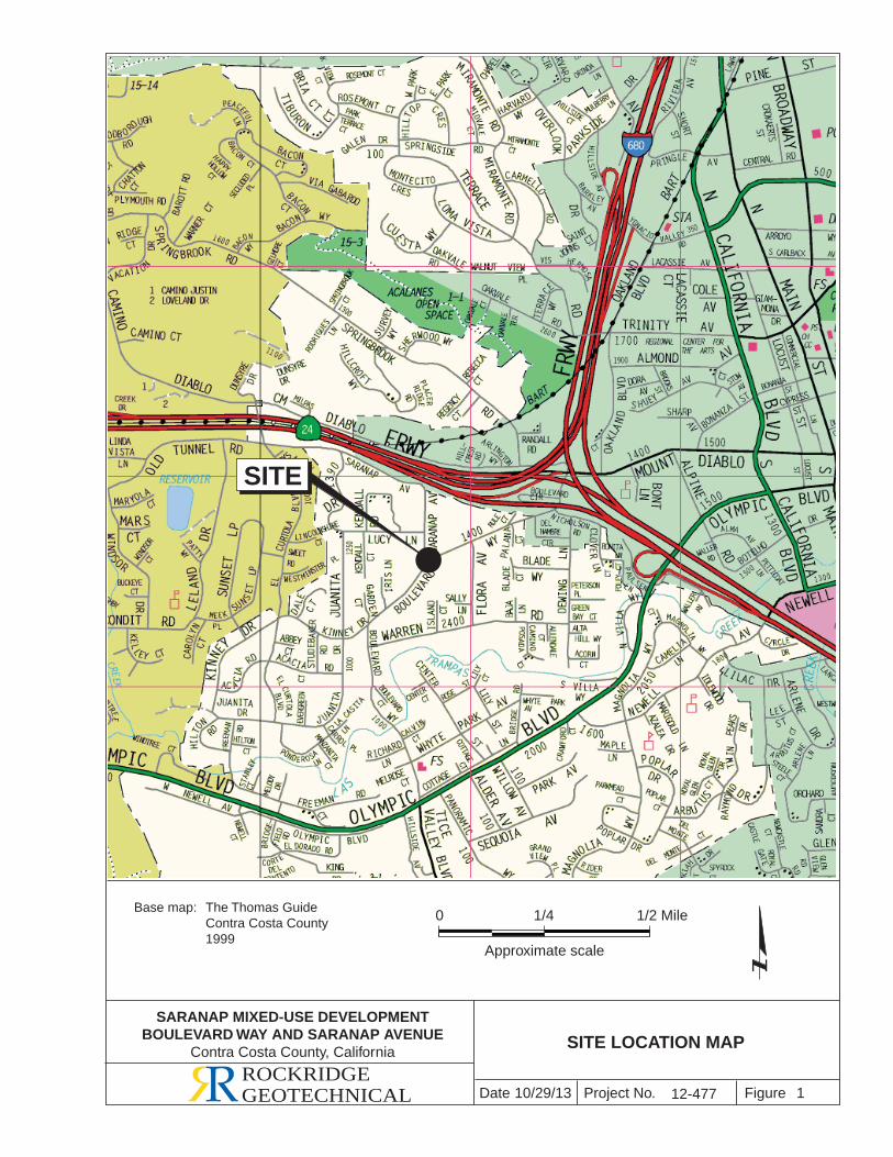
Project No. FigureDateROCKRIDGEGEOTECHNICAL 10/29/13 1
SITE LOCATION MAP
SITE
Base map: The Thomas Guide Contra Costa County 1999
0 1/2 Mile
Approximate scale
1/4
12-477
SARANAP MIXED-USE DEVELOPMENTBOULEVARD WAY AND SARANAP AVENUE
Contra Costa County, California
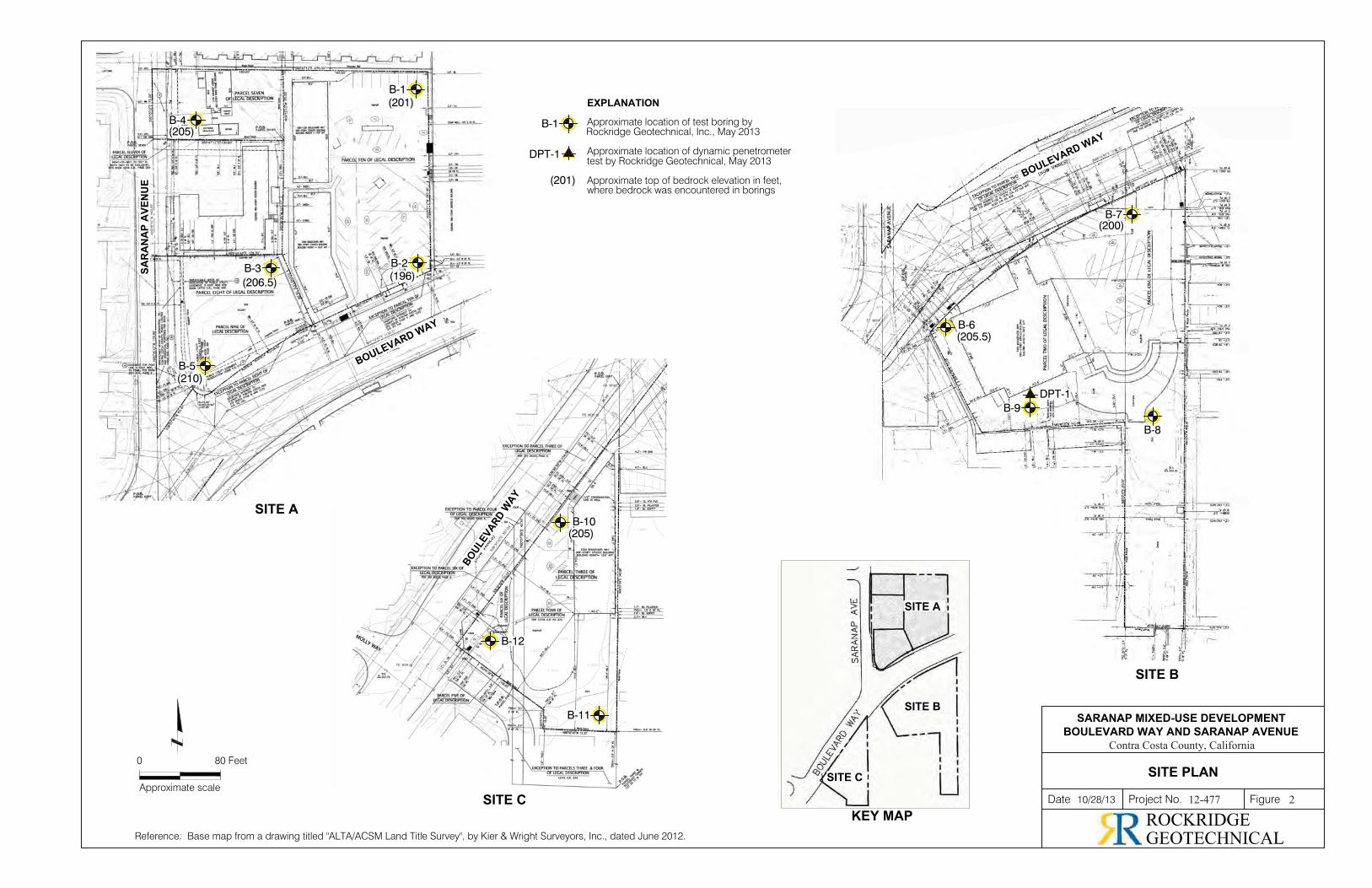
10/28/13
SITE PLAN
Date Project No. Figure
0
Approximate scale
80 Feet
Reference: Base map from a drawing titled "ALTA/ACSM Land Title Survey", by Kier & Wright Surveyors, Inc., dated June 2012.
Approximate location of test boring byRockridge Geotechnical, Inc., May 2013
Approximate location of dynamic penetrometertest by Rockridge Geotechnical, May 2013
Approximate top of bedrock elevation in feet,where bedrock was encountered in borings
EXPLANATION
B-11
B-12
SITE A
SITE B
SITE C
B-1
SARANAP MIXED-USE DEVELOPMENTBOULEVARD WAY AND SARANAP AVENUE
DPT-1
(201)
KEY MAP
SITE B
SITE A
B-8
B-9DPT-1
SAR
AN
AP
AVE
NU
E
BOULEVARD WAY
BOULEVA
RD WAY
BOULEVARD WAY
B-10(205)
B-4(205)
B-1(201)
B-2(196)
B-3(206.5)
B-5(210)
B-7(200)
B-6(205.5)
SITE C
Contra Costa County, California
12-477 2
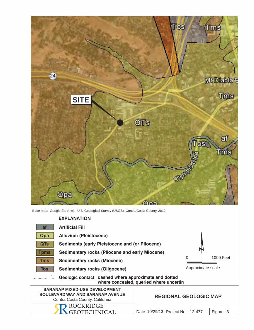
Project No. FigureDate
1000 Feet
Approximate scale
0
3
SITE
REGIONAL GEOLOGIC MAP
EXPLANATION
Base map: Google Earth with U.S. Geological Survey (USGS), Contra Costa County, 2012.
QTs
Geologic contact: dashed where approximate and dottedwhere concealed, queried where uncertin
ROCKRIDGEGEOTECHNICAL 10/29/13
Qha
Qpa
Artificial Fill
Alluvium (Pleistocene)
Sediments (early Pleistocene and (or Pilocene)
Sedimentary rocks (Pliocene and early Miocene)
Sedimentary rocks (Miocene)
Sedimentary rocks (Oligocene)
12-477
SARANAP MIXED-USE DEVELOPMENTBOULEVARD WAY AND SARANAP AVENUE
Contra Costa County, California
af
Qpa
QTs
Tpms
Tms
Tos
Tpms
Tes
Tepas
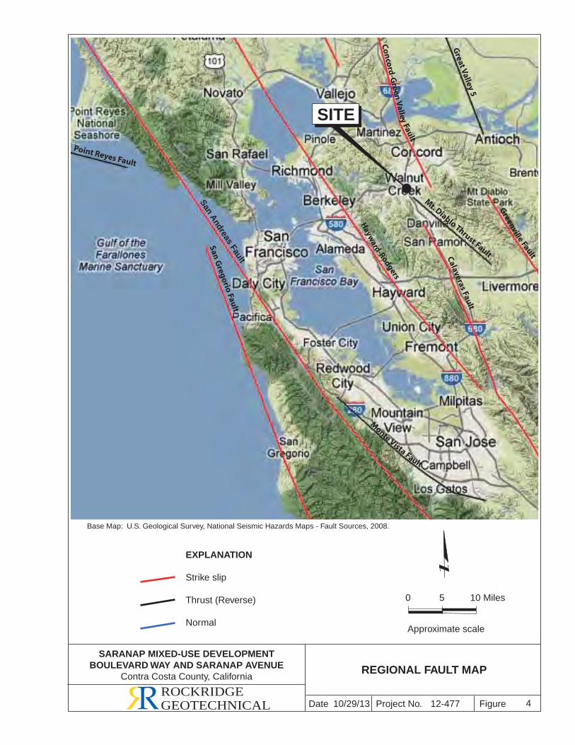
Project No. FigureDate
Base Map: U.S. Geological Survey, National Seismic Hazards Maps - Fault Sources, 2008.
10 Miles
Approximate scale
0 5
4ROCKRIDGEGEOTECHNICAL
REGIONAL FAULT MAP
San Andreas Fault
Hayw
ard-Rodgers
Calaveras Fault
San Gregorio Fault
EXPLANATION
Strike slip
Thrust (Reverse)
Normal
Monte Vista Fault
Mt. Diablo Thrust Fault
Great Valley 5
Greenville Fault
Point Reyes Fault
Co
nco
rd-G
reen V
alley Fault
SITE
10/29/13 12-477
SARANAP MIXED-USE DEVELOPMENTBOULEVARD WAY AND SARANAP AVENUE
Contra Costa County, California
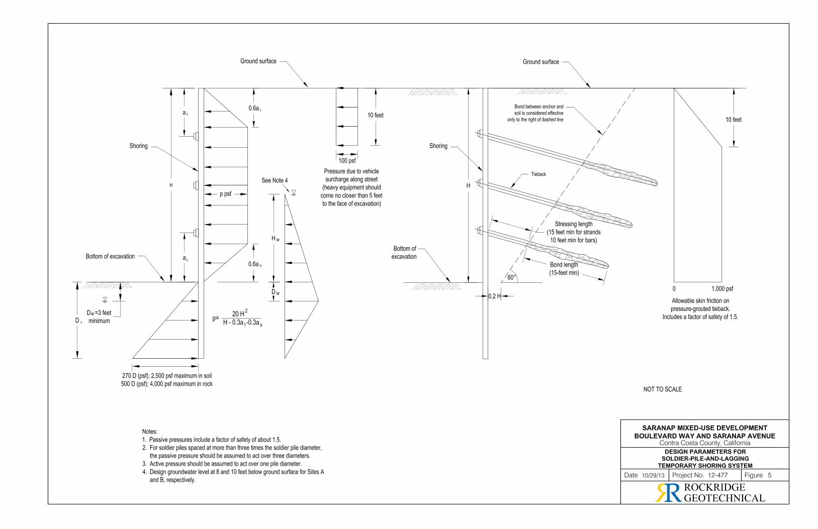

APPENDIX A
Boring Logs and DPT Results
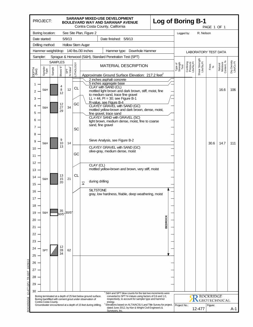
106
111
16.6
14.730.6
S&H
S&H
S&H
S&H
S&H
SPT
CL
GC
SC
GC
CL
2 inches asphalt concrete5 inches aggregate baseCLAY with SAND (CL)mottled light brown and dark brown, stiff, moist, fineto medium sand, trace fine gravelLL = 44, PI = 30; see Figure B-1R-value, see Figure B-4CLAYEY GRAVEL with SAND (GC)mottled yellow-brown and dark brown, dense, moist,fine gravel, trace sandCLAYEY SAND with GRAVEL (SC)light brown, medium dense, moist, fine to coarsesand, fine gravel
Sieve Analysis, see Figure B-2
CLAYEY GRAVEL with SAND (GC)olive-gray, medium dense, moist
CLAY (CL)mottled yellow-brown and brown, very stiff, moist
during drilling
SILTSTONEgray, low hardness, friable, deep weathering, moist
12
34
14
21
30/5"
62
4812
122729
91013
131520
3550/5"
122834
BED
RO
CK
Sa
mp
ler
Typ
e
Sa
mp
le
Blo
ws/
6"
SP
T
N-V
alu
e1
LIT
HO
LO
GY
DE
PT
H(f
ee
t)
Dry
De
nsity
Lb
s/C
u F
t
Typ
e o
fS
tre
ng
thT
est
Sh
ea
r S
tre
ng
th
Lb
s/S
q F
t
Fin
es
%
Co
nfin
ing
Pre
ssu
reL
bs/S
q F
t
Na
tura
lM
ois
ture
Co
nte
nt,
%
See Site Plan, Figure 2
5/9/13
Hollow Stem Auger
Logged by:
Hammer type: Downhole Hammer
Sprague & Henwood (S&H), Standard Penetration Test (SPT)
Date finished: 5/9/13
Hammer weight/drop: 140 lbs./30 inches
Sampler:
R. NelsonBoring location:
Date started:
Drilling method:
Approximate Ground Surface Elevation: 217.2 feet2
1
2
3
4
5
6
7
8
9
10
11
12
13
14
15
16
17
18
19
20
21
22
23
24
25
26
27
28
29
30
MATERIAL DESCRIPTION
LABORATORY TEST DATA
SAMPLES
Figure:
A-1
PROJECT:
Project No.:
12-477
SARANAP MIXED-USE DEVELOPMENTBOULEVARD WAY AND SARANAP AVENUE
Contra Costa County, California PAGE 1 OF 1
Log of Boring B-1R
OC
KR
IDG
E
12
-47
7.G
PJ
TR
.GD
T
10
/29
/13
Boring terminated at a depth of 25 feet below ground surface.Boring backfilled with cement grout under observation ofContra Costa County.Groundwater encountered at a depth of 15 feet during drilling.
1 S&H and SPT blow counts for the last two increments were
converted to SPT N-Values using factors of 0.6 and 1.0,respectively, to account for sampler type and hammerenergy.
2 Elevations based on ALTA/ACSU Land Title Survey for project,
dated June 2012, by Kier & Wright Civil Engineers &Surveyors, Inc.
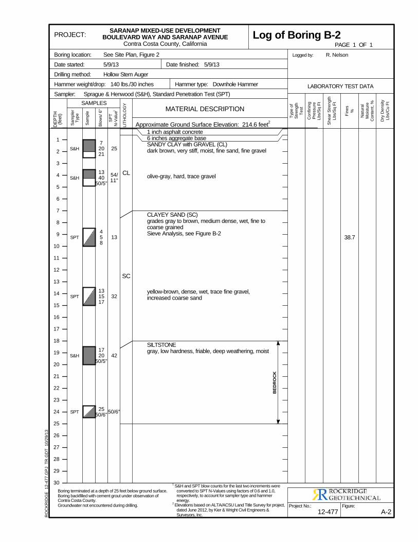
38.7
S&H
S&H
SPT
SPT
S&H
SPT
CL
SC
1 inch asphalt concrete6 inches aggregate baseSANDY CLAY with GRAVEL (CL)dark brown, very stiff, moist, fine sand, fine gravel
olive-gray, hard, trace gravel
CLAYEY SAND (SC)grades gray to brown, medium dense, wet, fine tocoarse grainedSieve Analysis, see Figure B-2
yellow-brown, dense, wet, trace fine gravel,increased coarse sand
SILTSTONEgray, low hardness, friable, deep weathering, moist
25
54/11"
13
32
42
50/6"
72021
1340
50/5"
458
131517
1720
50/5"
2550/6"
BED
RO
CK
Sa
mp
ler
Typ
e
Sa
mp
le
Blo
ws/
6"
SP
T
N-V
alu
e1
LIT
HO
LO
GY
DE
PT
H(f
ee
t)
Dry
De
nsity
Lb
s/C
u F
t
Typ
e o
fS
tre
ng
thT
est
Sh
ea
r S
tre
ng
th
Lb
s/S
q F
t
Fin
es
%
Co
nfin
ing
Pre
ssu
reL
bs/S
q F
t
Na
tura
lM
ois
ture
Co
nte
nt,
%
See Site Plan, Figure 2
5/9/13
Hollow Stem Auger
Logged by:
Hammer type: Downhole Hammer
Sprague & Henwood (S&H), Standard Penetration Test (SPT)
Date finished: 5/9/13
Hammer weight/drop: 140 lbs./30 inches
Sampler:
R. NelsonBoring location:
Date started:
Drilling method:
Approximate Ground Surface Elevation: 214.6 feet2
1
2
3
4
5
6
7
8
9
10
11
12
13
14
15
16
17
18
19
20
21
22
23
24
25
26
27
28
29
30
MATERIAL DESCRIPTION
LABORATORY TEST DATA
SAMPLES
Figure:
A-2
PROJECT:
Project No.:
12-477
SARANAP MIXED-USE DEVELOPMENTBOULEVARD WAY AND SARANAP AVENUE
Contra Costa County, California PAGE 1 OF 1
Log of Boring B-2R
OC
KR
IDG
E
12
-47
7.G
PJ
TR
.GD
T
10
/29
/13
Boring terminated at a depth of 25 feet below ground surface.Boring backfilled with cement grout under observation ofContra Costa County.Groundwater not encountered during drilling.
1 S&H and SPT blow counts for the last two increments were
converted to SPT N-Values using factors of 0.6 and 1.0,respectively, to account for sampler type and hammerenergy.
2 Elevations based on ALTA/ACSU Land Title Survey for project,
dated June 2012, by Kier & Wright Civil Engineers &Surveyors, Inc.
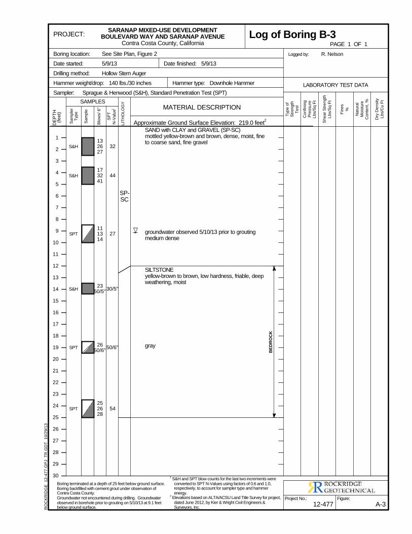
S&H
S&H
SPT
S&H
SPT
SPT
SP-SC
SAND with CLAY and GRAVEL (SP-SC)mottled yellow-brown and brown, dense, moist, fineto coarse sand, fine gravel
groundwater observed 5/10/13 prior to groutingmedium dense
SILTSTONEyellow-brown to brown, low hardness, friable, deepweathering, moist
gray
32
44
27
30/5"
50/6"
54
132627
173241
111314
2350/5"
2650/6"
252628
BED
RO
CK
Sa
mp
ler
Typ
e
Sa
mp
le
Blo
ws/
6"
SP
T
N-V
alu
e1
LIT
HO
LO
GY
DE
PT
H(f
ee
t)
Dry
De
nsity
Lb
s/C
u F
t
Typ
e o
fS
tre
ng
thT
est
Sh
ea
r S
tre
ng
th
Lb
s/S
q F
t
Fin
es
%
Co
nfin
ing
Pre
ssu
reL
bs/S
q F
t
Na
tura
lM
ois
ture
Co
nte
nt,
%
See Site Plan, Figure 2
5/9/13
Hollow Stem Auger
Logged by:
Hammer type: Downhole Hammer
Sprague & Henwood (S&H), Standard Penetration Test (SPT)
Date finished: 5/9/13
Hammer weight/drop: 140 lbs./30 inches
Sampler:
R. NelsonBoring location:
Date started:
Drilling method:
Approximate Ground Surface Elevation: 219.0 feet2
1
2
3
4
5
6
7
8
9
10
11
12
13
14
15
16
17
18
19
20
21
22
23
24
25
26
27
28
29
30
MATERIAL DESCRIPTION
LABORATORY TEST DATA
SAMPLES
Figure:
A-3
PROJECT:
Project No.:
12-477
SARANAP MIXED-USE DEVELOPMENTBOULEVARD WAY AND SARANAP AVENUE
Contra Costa County, California PAGE 1 OF 1
Log of Boring B-3R
OC
KR
IDG
E
12
-47
7.G
PJ
TR
.GD
T
10
/29
/13
Boring terminated at a depth of 25 feet below ground surface.Boring backfilled with cement grout under observation ofContra Costa County.Groundwater not encountered during drilling. Groundwaterobserved in borehole prior to grouting on 5/10/13 at 9.1 feetbelow ground surface.
1 S&H and SPT blow counts for the last two increments were
converted to SPT N-Values using factors of 0.6 and 1.0,respectively, to account for sampler type and hammerenergy.
2 Elevations based on ALTA/ACSU Land Title Survey for project,
dated June 2012, by Kier & Wright Civil Engineers &Surveyors, Inc.
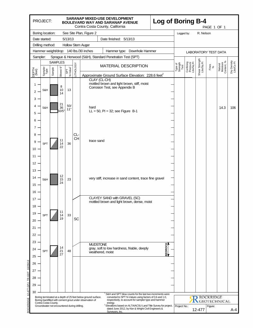
10614.3
S&H
S&H
SPT
S&H
SPT
SPT
CL-CH
SC
CLAY (CL-CH)mottled brown and light brown, stiff, moistCorrosion Test, see Appendix B
hardLL = 50, PI = 32; see Figure B-1
trace sand
very stiff, increase in sand content, trace fine gravel
CLAYEY SAND with GRAVEL (SC)mottled brown and light brown, dense, moist
MUDSTONEgray, soft to low hardness, friable, deeplyweathered, moist
13
50/11"
36
23
33
48
81014
2136
50/5"
111422
121524
111419
142127 B
EDR
OC
K
Sa
mp
ler
Typ
e
Sa
mp
le
Blo
ws/
6"
SP
T
N-V
alu
e1
LIT
HO
LO
GY
DE
PT
H(f
ee
t)
Dry
De
nsity
Lb
s/C
u F
t
Typ
e o
fS
tre
ng
thT
est
Sh
ea
r S
tre
ng
th
Lb
s/S
q F
t
Fin
es
%
Co
nfin
ing
Pre
ssu
reL
bs/S
q F
t
Na
tura
lM
ois
ture
Co
nte
nt,
%
See Site Plan, Figure 2
5/13/13
Hollow Stem Auger
Logged by:
Hammer type: Downhole Hammer
Sprague & Henwood (S&H), Standard Penetration Test (SPT)
Date finished: 5/13/13
Hammer weight/drop: 140 lbs./30 inches
Sampler:
R. NelsonBoring location:
Date started:
Drilling method:
Approximate Ground Surface Elevation: 228.6 feet2
1
2
3
4
5
6
7
8
9
10
11
12
13
14
15
16
17
18
19
20
21
22
23
24
25
26
27
28
29
30
MATERIAL DESCRIPTION
LABORATORY TEST DATA
SAMPLES
Figure:
A-4
PROJECT:
Project No.:
12-477
SARANAP MIXED-USE DEVELOPMENTBOULEVARD WAY AND SARANAP AVENUE
Contra Costa County, California PAGE 1 OF 1
Log of Boring B-4R
OC
KR
IDG
E
12
-47
7.G
PJ
TR
.GD
T
10
/29
/13
Boring terminated at a depth of 25 feet below ground surface.Boring backfilled with cement grout under observation ofContra Costa County.Groundwater not encountered during drilling.
1 S&H and SPT blow counts for the last two increments were
converted to SPT N-Values using factors of 0.6 and 1.0,respectively, to account for sampler type and hammerenergy.
2 Elevations based on ALTA/ACSU Land Title Survey for project,
dated June 2012, by Kier & Wright Civil Engineers &Surveyors, Inc.
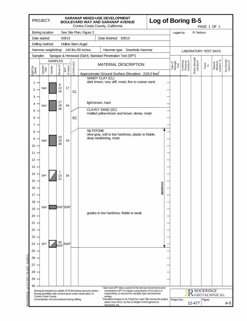
S&H
S&H
S&H
SPT
S&H
SPT
CL
SC
SANDY CLAY (CL)dark brown, very stiff, moist, fine to coarse sand
light-brown, hard
CLAYEY SAND (SC)mottled yellow-brown and brown, dense, moist
SILTSTONEolive-gray, soft to low hardness, plastic to friable,deep weathering, moist
grades to low hardness, friable to weak
17
44
43
34
30/6"
50/6"
81216
172846
233338
71321
50/6"
3050/6"
BED
RO
CK
Sa
mp
ler
Typ
e
Sa
mp
le
Blo
ws/
6"
SP
T
N-V
alu
e1
LIT
HO
LO
GY
DE
PT
H(f
ee
t)
Dry
De
nsity
Lb
s/C
u F
t
Typ
e o
fS
tre
ng
thT
est
Sh
ea
r S
tre
ng
th
Lb
s/S
q F
t
Fin
es
%
Co
nfin
ing
Pre
ssu
reL
bs/S
q F
t
Na
tura
lM
ois
ture
Co
nte
nt,
%
See Site Plan, Figure 2
5/9/13
Hollow Stem Auger
Logged by:
Hammer type: Downhole Hammer
Sprague & Henwood (S&H), Standard Penetration Test (SPT)
Date finished: 5/9/13
Hammer weight/drop: 140 lbs./30 inches
Sampler:
R. NelsonBoring location:
Date started:
Drilling method:
Approximate Ground Surface Elevation: 218.0 feet2
1
2
3
4
5
6
7
8
9
10
11
12
13
14
15
16
17
18
19
20
21
22
23
24
25
26
27
28
29
30
MATERIAL DESCRIPTION
LABORATORY TEST DATA
SAMPLES
Figure:
A-5
PROJECT:
Project No.:
12-477
SARANAP MIXED-USE DEVELOPMENTBOULEVARD WAY AND SARANAP AVENUE
Contra Costa County, California PAGE 1 OF 1
Log of Boring B-5R
OC
KR
IDG
E
12
-47
7.G
PJ
TR
.GD
T
10
/29
/13
Boring terminated at a depth of 25 feet below ground surface.Boring backfilled with cement grout under observation ofContra Costa County.Groundwater not encountered during drilling.
1 S&H and SPT blow counts for the last two increments were
converted to SPT N-Values using factors of 0.6 and 1.0,respectively, to account for sampler type and hammerenergy.
2 Elevations based on ALTA/ACSU Land Title Survey for project,
dated June 2012, by Kier & Wright Civil Engineers &Surveyors, Inc.
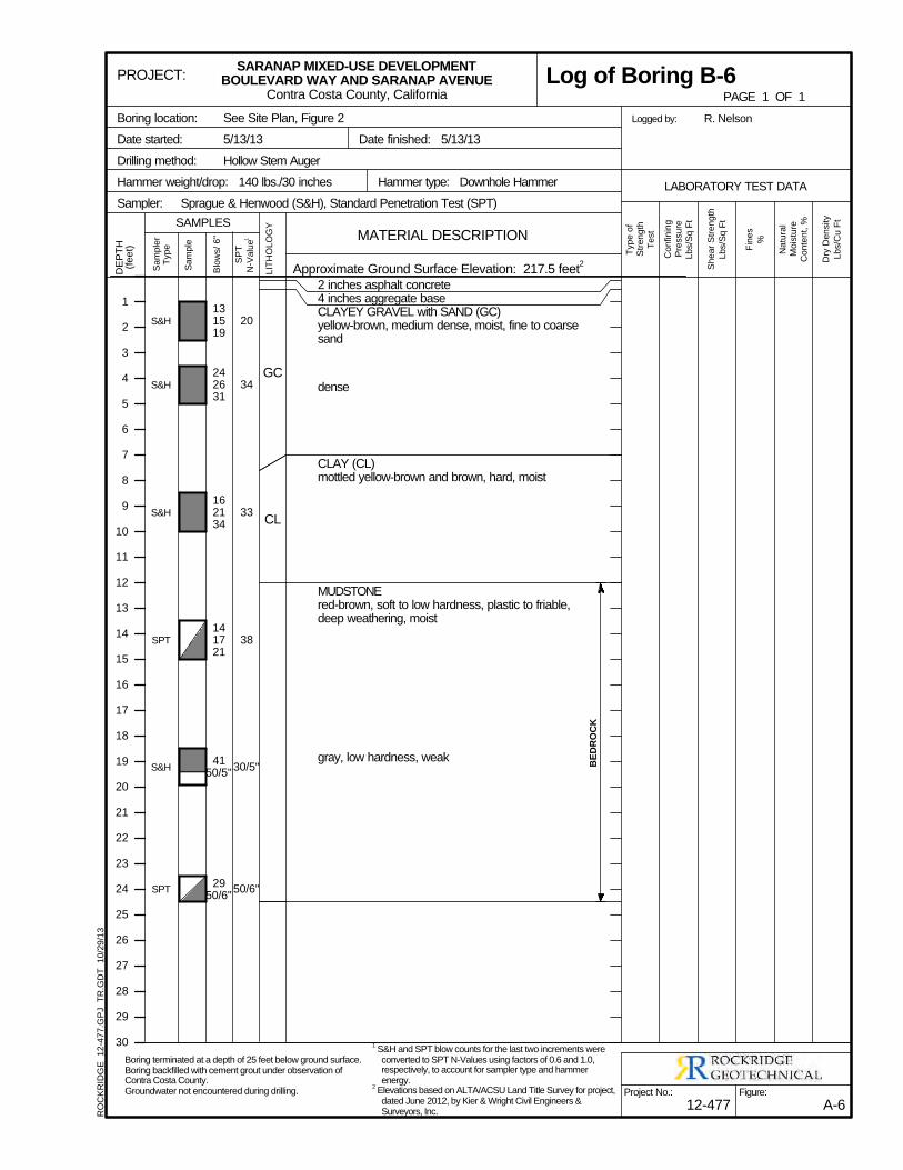
Dry
De
nsity
Lb
s/C
u F
t
Typ
e o
fS
tre
ng
thT
est
Sh
ea
r S
tre
ng
th
Lb
s/S
q F
t
Fin
es
%
Co
nfin
ing
Pre
ssu
reL
bs/S
q F
t
Na
tura
lM
ois
ture
Co
nte
nt,
%
See Site Plan, Figure 2
5/13/13
Hollow Stem Auger
Logged by:
Hammer type: Downhole Hammer
Sprague & Henwood (S&H), Standard Penetration Test (SPT)
Date finished: 5/13/13
Hammer weight/drop: 140 lbs./30 inches
S&H
S&H
S&H
SPT
S&H
SPT
GC
CL
2 inches asphalt concrete4 inches aggregate baseCLAYEY GRAVEL with SAND (GC)yellow-brown, medium dense, moist, fine to coarsesand
dense
CLAY (CL)mottled yellow-brown and brown, hard, moist
MUDSTONEred-brown, soft to low hardness, plastic to friable,deep weathering, moist
gray, low hardness, weak
20
34
33
38
30/5"
50/6"
131519
242631
162134
141721
4150/5"
2950/6"
BED
RO
CK
Sa
mp
ler
Typ
e
Sa
mp
le
Blo
ws/
6"
SP
T
N-V
alu
e1
LIT
HO
LO
GY
DE
PT
H(f
ee
t)
Sampler:
R. NelsonBoring location:
Date started:
Drilling method:
Approximate Ground Surface Elevation: 217.5 feet2
1
2
3
4
5
6
7
8
9
10
11
12
13
14
15
16
17
18
19
20
21
22
23
24
25
26
27
28
29
30
MATERIAL DESCRIPTION
LABORATORY TEST DATA
SAMPLES
Figure:
A-6
PROJECT:
Project No.:
12-477
SARANAP MIXED-USE DEVELOPMENTBOULEVARD WAY AND SARANAP AVENUE
Contra Costa County, California PAGE 1 OF 1
Log of Boring B-6R
OC
KR
IDG
E
12
-47
7.G
PJ
TR
.GD
T
10
/29
/13
Boring terminated at a depth of 25 feet below ground surface.Boring backfilled with cement grout under observation ofContra Costa County.Groundwater not encountered during drilling.
1 S&H and SPT blow counts for the last two increments were
converted to SPT N-Values using factors of 0.6 and 1.0,respectively, to account for sampler type and hammerenergy.
2 Elevations based on ALTA/ACSU Land Title Survey for project,
dated June 2012, by Kier & Wright Civil Engineers &Surveyors, Inc.
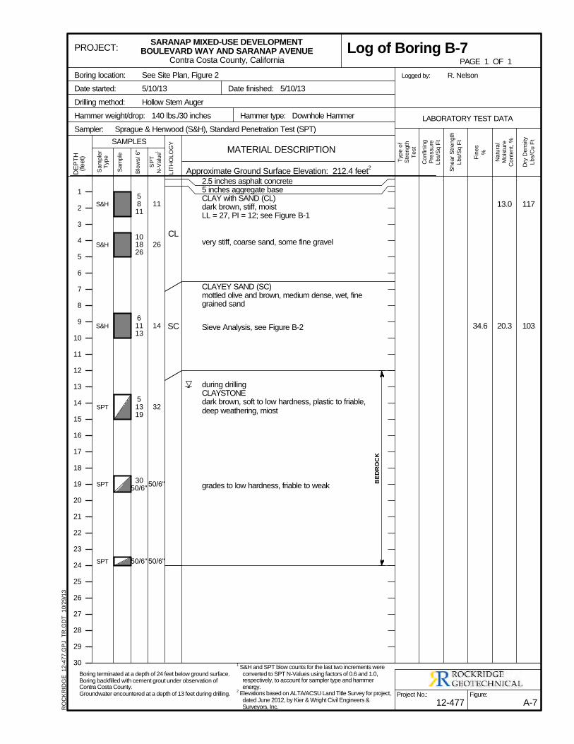
117
103
13.0
20.334.6
S&H
S&H
S&H
SPT
SPT
SPT
CL
SC
2.5 inches asphalt concrete5 inches aggregate baseCLAY with SAND (CL)dark brown, stiff, moistLL = 27, PI = 12; see Figure B-1
very stiff, coarse sand, some fine gravel
CLAYEY SAND (SC)mottled olive and brown, medium dense, wet, finegrained sand
Sieve Analysis, see Figure B-2
during drillingCLAYSTONEdark brown, soft to low hardness, plastic to friable,deep weathering, miost
grades to low hardness, friable to weak
11
26
14
32
50/6"
50/6"
5811
101826
61113
51319
3050/6"
50/6"
BED
RO
CK
Sa
mp
ler
Typ
e
Sa
mp
le
Blo
ws/
6"
SP
T
N-V
alu
e1
LIT
HO
LO
GY
DE
PT
H(f
ee
t)
Dry
De
nsity
Lb
s/C
u F
t
Typ
e o
fS
tre
ng
thT
est
Sh
ea
r S
tre
ng
th
Lb
s/S
q F
t
Fin
es
%
Co
nfin
ing
Pre
ssu
reL
bs/S
q F
t
Na
tura
lM
ois
ture
Co
nte
nt,
%
See Site Plan, Figure 2
5/10/13
Hollow Stem Auger
Logged by:
Hammer type: Downhole Hammer
Sprague & Henwood (S&H), Standard Penetration Test (SPT)
Date finished: 5/10/13
Hammer weight/drop: 140 lbs./30 inches
Sampler:
R. NelsonBoring location:
Date started:
Drilling method:
Approximate Ground Surface Elevation: 212.4 feet2
1
2
3
4
5
6
7
8
9
10
11
12
13
14
15
16
17
18
19
20
21
22
23
24
25
26
27
28
29
30
MATERIAL DESCRIPTION
LABORATORY TEST DATA
SAMPLES
Figure:
A-7
PROJECT:
Project No.:
12-477
SARANAP MIXED-USE DEVELOPMENTBOULEVARD WAY AND SARANAP AVENUE
Contra Costa County, California PAGE 1 OF 1
Log of Boring B-7R
OC
KR
IDG
E
12
-47
7.G
PJ
TR
.GD
T
10
/29
/13
Boring terminated at a depth of 24 feet below ground surface.Boring backfilled with cement grout under observation ofContra Costa County.Groundwater encountered at a depth of 13 feet during drilling.
1 S&H and SPT blow counts for the last two increments were
converted to SPT N-Values using factors of 0.6 and 1.0,respectively, to account for sampler type and hammerenergy.
2 Elevations based on ALTA/ACSU Land Title Survey for project,
dated June 2012, by Kier & Wright Civil Engineers &Surveyors, Inc.
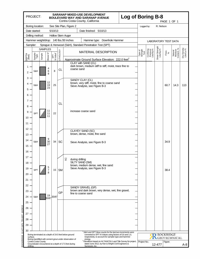
11314.360.7
34.9
38.4
S&H
S&H
SPT
S&H
SPT
S&H
CL
CL
SC
SM
GP
CLAY with SAND (CL)dark brown, medium stiff to stiff, moist, trace fine tocoarse sand
SANDY CLAY (CL)brown, very stiff, moist, fine to coarse sandSieve Analysis, see Figure B-3
increase coarse sand
CLAYEY SAND (SC)brown, dense, moist, fine sand
Sieve Analysis, see Figure B-3
during drillingSILTY SAND (SM)brown, medium dense, wet, fine sandSieve Analysis, see Figure B-3
SANDY GRAVEL (GP)brown and dark brown, very dense, wet, fine gravel,fine to coarse sand
8
25
22
34
15
30/6"
468
121923
111111
93027
578
1950/6"
Sa
mp
ler
Typ
e
Sa
mp
le
Blo
ws/
6"
SP
T
N-V
alu
e1
LIT
HO
LO
GY
DE
PT
H(f
ee
t)
Dry
De
nsity
Lb
s/C
u F
t
Typ
e o
fS
tre
ng
thT
est
Sh
ea
r S
tre
ng
th
Lb
s/S
q F
t
Fin
es
%
Co
nfin
ing
Pre
ssu
reL
bs/S
q F
t
Na
tura
lM
ois
ture
Co
nte
nt,
%
See Site Plan, Figure 2
5/10/13
Hollow Stem Auger
Logged by:
Hammer type: Downhole Hammer
Sprague & Henwood (S&H), Standard Penetration Test (SPT)
Date finished: 5/10/13
Hammer weight/drop: 140 lbs./30 inches
Sampler:
R. NelsonBoring location:
Date started:
Drilling method:
Approximate Ground Surface Elevation: 222.0 feet2
1
2
3
4
5
6
7
8
9
10
11
12
13
14
15
16
17
18
19
20
21
22
23
24
25
26
27
28
29
30
MATERIAL DESCRIPTION
LABORATORY TEST DATA
SAMPLES
Figure:
A-8
PROJECT:
Project No.:
12-477
SARANAP MIXED-USE DEVELOPMENTBOULEVARD WAY AND SARANAP AVENUE
Contra Costa County, California PAGE 1 OF 1
Log of Boring B-8R
OC
KR
IDG
E
12
-47
7.G
PJ
TR
.GD
T
10
/29
/13
Boring terminated at a depth of 24.5 feet below groundsurface.Boring backfilled with cement grout under observation ofContra Costa County.Groundwater encountered at a depth of 17.5 feet duringdrilling.
1 S&H and SPT blow counts for the last two increments were
converted to SPT N-Values using factors of 0.6 and 1.0,respectively, to account for sampler type and hammerenergy.
2 Elevations based on ALTA/ACSU Land Title Survey for project,
dated June 2012, by Kier & Wright Civil Engineers &Surveyors, Inc.
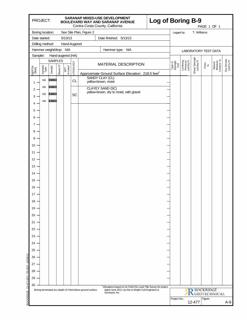
HA
HA
HA
HA
CL
SC
SANDY CLAY (CL)yellow-brown, moist
CLAYEY SAND (SC)yellow-brown, dry to moist, with gravel
Sa
mp
ler
Typ
e
Sa
mp
le
Blo
ws/
6"
SP
T
N-V
alu
e1
LIT
HO
LO
GY
DE
PT
H(f
ee
t)
Dry
De
nsity
Lb
s/C
u F
t
Typ
e o
fS
tre
ng
thT
est
Sh
ea
r S
tre
ng
th
Lb
s/S
q F
t
Fin
es
%
Co
nfin
ing
Pre
ssu
reL
bs/S
q F
t
Na
tura
lM
ois
ture
Co
nte
nt,
%
See Site Plan, Figure 2
5/13/13
Hand-Augered
Logged by:
Hammer type: N/A
Hand-augered (HA)
Date finished: 5/13/13
Hammer weight/drop: N/A
Sampler:
T. WilliamsBoring location:
Date started:
Drilling method:
Approximate Ground Surface Elevation: 218.5 feet1
1
2
3
4
5
6
7
8
9
10
11
12
13
14
15
16
17
18
19
20
21
22
23
24
25
26
27
28
29
30
MATERIAL DESCRIPTION
LABORATORY TEST DATA
SAMPLES
Figure:
A-9
PROJECT:
Project No.:
12-477
SARANAP MIXED-USE DEVELOPMENTBOULEVARD WAY AND SARANAP AVENUE
Contra Costa County, California PAGE 1 OF 1
Log of Boring B-9R
OC
KR
IDG
E
12
-47
7.G
PJ
TR
.GD
T
10
/29
/13
Boring terminated at a depth of 4 feet below ground surface.
1 Elevations based on ALTA/ACSU Land Title Survey for project,
dated June 2012, by Kier & Wright Civil Engineers &Surveyors, Inc.
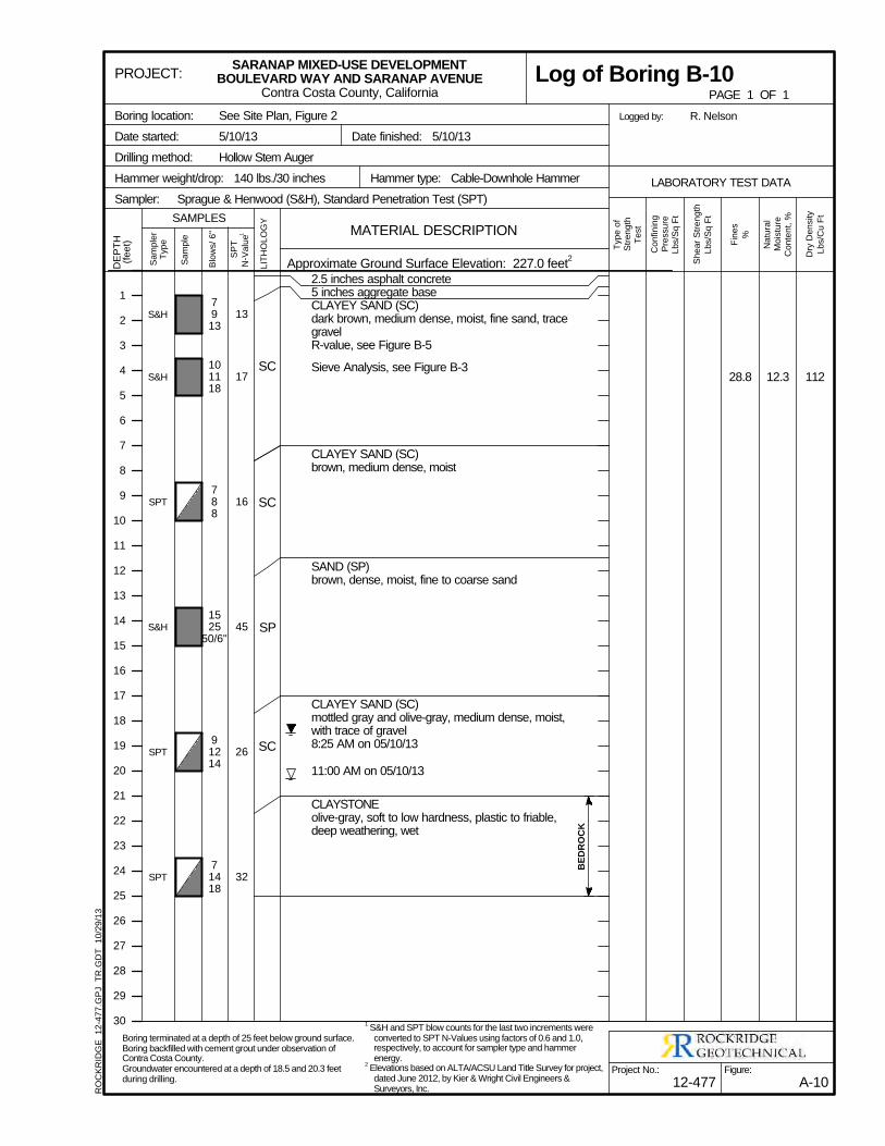
11212.328.8
S&H
S&H
SPT
S&H
SPT
SPT
SC
SC
SP
SC
2.5 inches asphalt concrete5 inches aggregate baseCLAYEY SAND (SC)dark brown, medium dense, moist, fine sand, tracegravelR-value, see Figure B-5
Sieve Analysis, see Figure B-3
CLAYEY SAND (SC)brown, medium dense, moist
SAND (SP)brown, dense, moist, fine to coarse sand
CLAYEY SAND (SC)mottled gray and olive-gray, medium dense, moist,with trace of gravel8:25 AM on 05/10/13
11:00 AM on 05/10/13
CLAYSTONEolive-gray, soft to low hardness, plastic to friable,deep weathering, wet
13
17
16
45
26
32
7913
101118
788
1525
50/6"
91214
71418
BED
RO
CK
Sa
mp
ler
Typ
e
Sa
mp
le
Blo
ws/
6"
SP
T
N-V
alu
e1
LIT
HO
LO
GY
DE
PT
H(f
ee
t)
Dry
De
nsity
Lb
s/C
u F
t
Typ
e o
fS
tre
ng
thT
est
Sh
ea
r S
tre
ng
th
Lb
s/S
q F
t
Fin
es
%
Co
nfin
ing
Pre
ssu
reL
bs/S
q F
t
Na
tura
lM
ois
ture
Co
nte
nt,
%
See Site Plan, Figure 2
5/10/13
Hollow Stem Auger
Logged by:
Hammer type: Cable-Downhole Hammer
Sprague & Henwood (S&H), Standard Penetration Test (SPT)
Date finished: 5/10/13
Hammer weight/drop: 140 lbs./30 inches
Sampler:
R. NelsonBoring location:
Date started:
Drilling method:
Approximate Ground Surface Elevation: 227.0 feet2
1
2
3
4
5
6
7
8
9
10
11
12
13
14
15
16
17
18
19
20
21
22
23
24
25
26
27
28
29
30
MATERIAL DESCRIPTION
LABORATORY TEST DATA
SAMPLES
Figure:
A-10
PROJECT:
Project No.:
12-477
SARANAP MIXED-USE DEVELOPMENTBOULEVARD WAY AND SARANAP AVENUE
Contra Costa County, California PAGE 1 OF 1
Log of Boring B-10R
OC
KR
IDG
E
12
-47
7.G
PJ
TR
.GD
T
10
/29
/13
Boring terminated at a depth of 25 feet below ground surface.Boring backfilled with cement grout under observation ofContra Costa County.Groundwater encountered at a depth of 18.5 and 20.3 feetduring drilling.
1 S&H and SPT blow counts for the last two increments were
converted to SPT N-Values using factors of 0.6 and 1.0,respectively, to account for sampler type and hammerenergy.
2 Elevations based on ALTA/ACSU Land Title Survey for project,
dated June 2012, by Kier & Wright Civil Engineers &Surveyors, Inc.
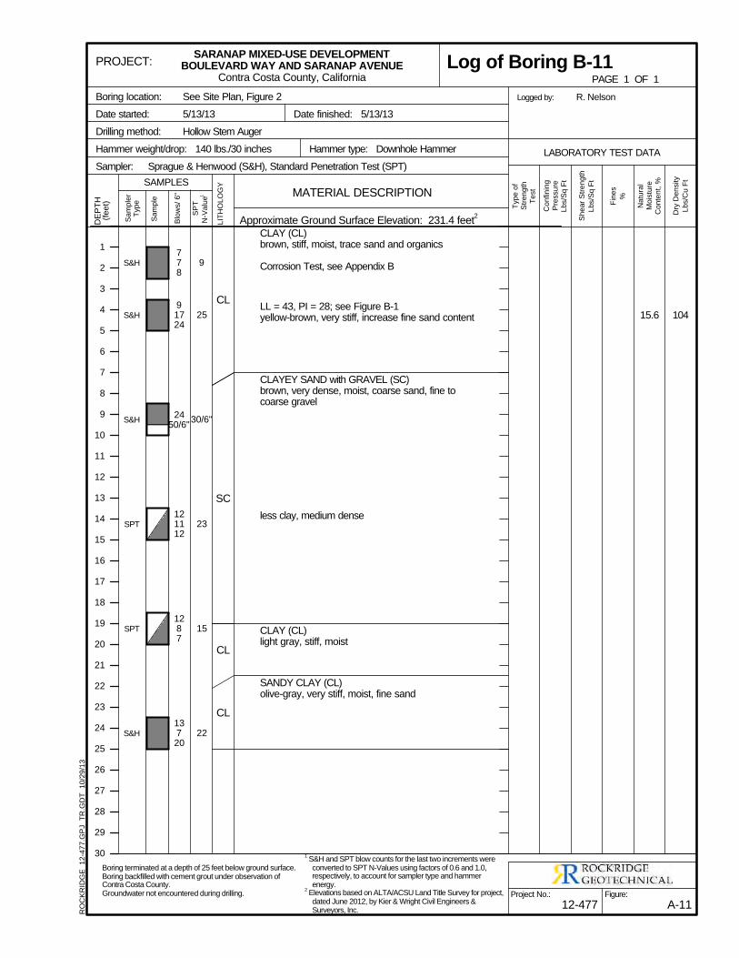
10415.6
S&H
S&H
S&H
SPT
SPT
S&H
CL
SC
CL
CL
CLAY (CL)brown, stiff, moist, trace sand and organics
Corrosion Test, see Appendix B
LL = 43, PI = 28; see Figure B-1yellow-brown, very stiff, increase fine sand content
CLAYEY SAND with GRAVEL (SC)brown, very dense, moist, coarse sand, fine tocoarse gravel
less clay, medium dense
CLAY (CL)light gray, stiff, moist
SANDY CLAY (CL)olive-gray, very stiff, moist, fine sand
9
25
30/6"
23
15
22
778
91724
2450/6"
121112
1287
13720
Sa
mp
ler
Typ
e
Sa
mp
le
Blo
ws/
6"
SP
T
N-V
alu
e1
LIT
HO
LO
GY
DE
PT
H(f
ee
t)
Dry
De
nsity
Lb
s/C
u F
t
Typ
e o
fS
tre
ng
thT
est
Sh
ea
r S
tre
ng
th
Lb
s/S
q F
t
Fin
es
%
Co
nfin
ing
Pre
ssu
reL
bs/S
q F
t
Na
tura
lM
ois
ture
Co
nte
nt,
%
See Site Plan, Figure 2
5/13/13
Hollow Stem Auger
Logged by:
Hammer type: Downhole Hammer
Sprague & Henwood (S&H), Standard Penetration Test (SPT)
Date finished: 5/13/13
Hammer weight/drop: 140 lbs./30 inches
Sampler:
R. NelsonBoring location:
Date started:
Drilling method:
Approximate Ground Surface Elevation: 231.4 feet2
1
2
3
4
5
6
7
8
9
10
11
12
13
14
15
16
17
18
19
20
21
22
23
24
25
26
27
28
29
30
MATERIAL DESCRIPTION
LABORATORY TEST DATA
SAMPLES
Figure:
A-11
PROJECT:
Project No.:
12-477
SARANAP MIXED-USE DEVELOPMENTBOULEVARD WAY AND SARANAP AVENUE
Contra Costa County, California PAGE 1 OF 1
Log of Boring B-11R
OC
KR
IDG
E
12
-47
7.G
PJ
TR
.GD
T
10
/29
/13
Boring terminated at a depth of 25 feet below ground surface.Boring backfilled with cement grout under observation ofContra Costa County.Groundwater not encountered during drilling.
1 S&H and SPT blow counts for the last two increments were
converted to SPT N-Values using factors of 0.6 and 1.0,respectively, to account for sampler type and hammerenergy.
2 Elevations based on ALTA/ACSU Land Title Survey for project,
dated June 2012, by Kier & Wright Civil Engineers &Surveyors, Inc.
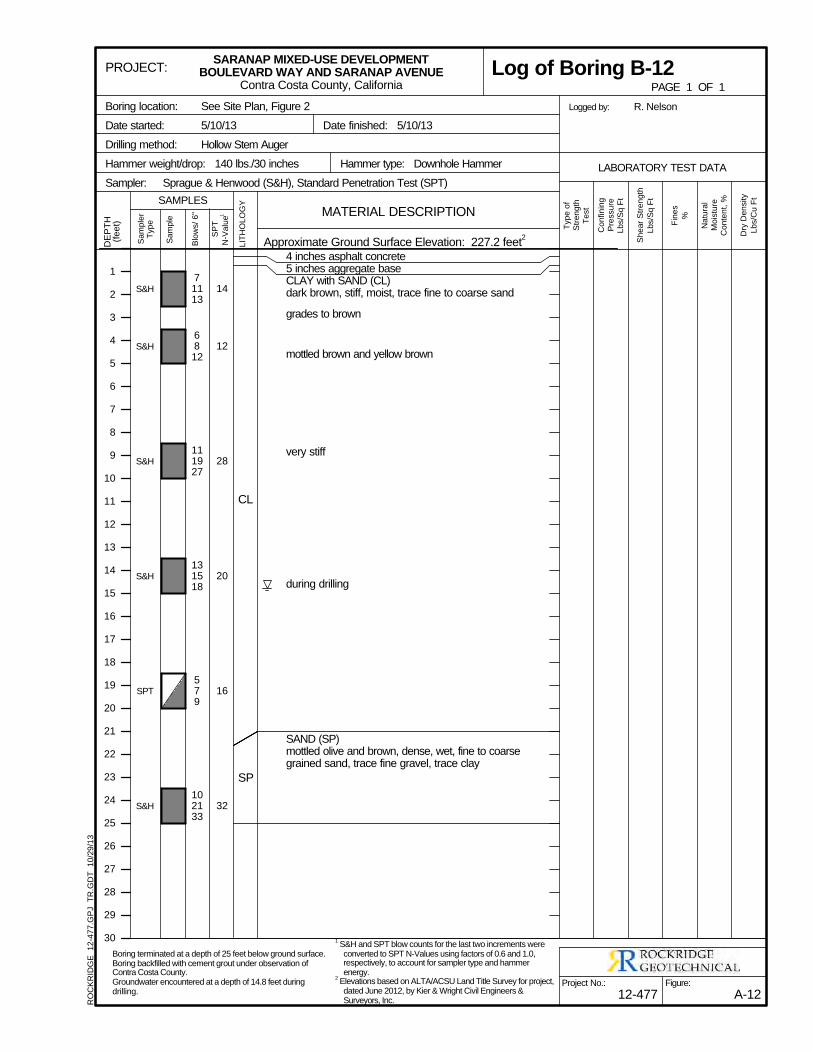
S&H
S&H
S&H
S&H
SPT
S&H
CL
SP
4 inches asphalt concrete5 inches aggregate baseCLAY with SAND (CL)dark brown, stiff, moist, trace fine to coarse sand
grades to brown
mottled brown and yellow brown
very stiff
during drilling
SAND (SP)mottled olive and brown, dense, wet, fine to coarsegrained sand, trace fine gravel, trace clay
14
12
28
20
16
32
71113
6812
111927
131518
579
102133
Sa
mp
ler
Typ
e
Sa
mp
le
Blo
ws/
6"
SP
T
N-V
alu
e1
LIT
HO
LO
GY
DE
PT
H(f
ee
t)
Dry
De
nsity
Lb
s/C
u F
t
Typ
e o
fS
tre
ng
thT
est
Sh
ea
r S
tre
ng
th
Lb
s/S
q F
t
Fin
es
%
Co
nfin
ing
Pre
ssu
reL
bs/S
q F
t
Na
tura
lM
ois
ture
Co
nte
nt,
%
See Site Plan, Figure 2
5/10/13
Hollow Stem Auger
Logged by:
Hammer type: Downhole Hammer
Sprague & Henwood (S&H), Standard Penetration Test (SPT)
Date finished: 5/10/13
Hammer weight/drop: 140 lbs./30 inches
Sampler:
R. NelsonBoring location:
Date started:
Drilling method:
Approximate Ground Surface Elevation: 227.2 feet2
1
2
3
4
5
6
7
8
9
10
11
12
13
14
15
16
17
18
19
20
21
22
23
24
25
26
27
28
29
30
MATERIAL DESCRIPTION
LABORATORY TEST DATA
SAMPLES
Figure:
A-12
PROJECT:
Project No.:
12-477
SARANAP MIXED-USE DEVELOPMENTBOULEVARD WAY AND SARANAP AVENUE
Contra Costa County, California PAGE 1 OF 1
Log of Boring B-12R
OC
KR
IDG
E
12
-47
7.G
PJ
TR
.GD
T
10
/29
/13
Boring terminated at a depth of 25 feet below ground surface.Boring backfilled with cement grout under observation ofContra Costa County.Groundwater encountered at a depth of 14.8 feet duringdrilling.
1 S&H and SPT blow counts for the last two increments were
converted to SPT N-Values using factors of 0.6 and 1.0,respectively, to account for sampler type and hammerenergy.
2 Elevations based on ALTA/ACSU Land Title Survey for project,
dated June 2012, by Kier & Wright Civil Engineers &Surveyors, Inc.
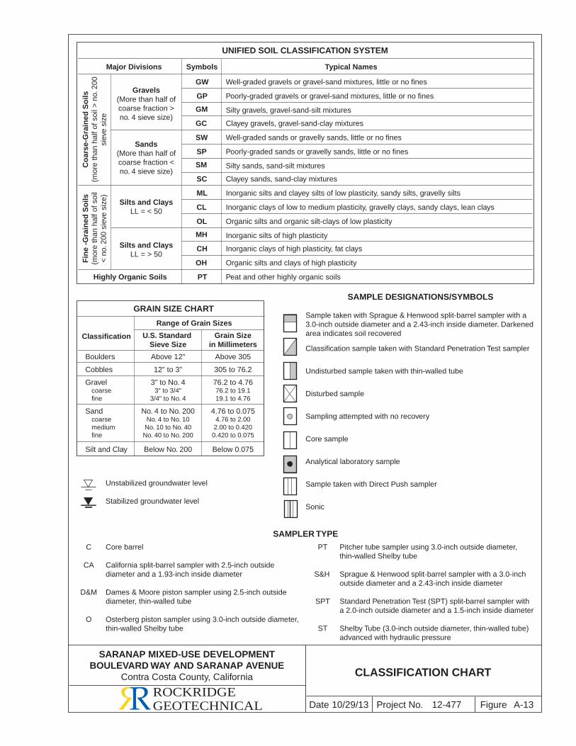
Project No. FigureDate 10/29/13 A-13
CLASSIFICATION CHART
Major Divisions Symbols Typical Names
GW
GP
GM
GC
SW
SP
SM
SC
ML
CL
OL
MH
CH
OH
PTHighly Organic Soils
UNIFIED SOIL CLASSIFICATION SYSTEM
Well-graded gravels or gravel-sand mixtures, little or no fines
Poorly-graded gravels or gravel-sand mixtures, little or no fines
Silty gravels, gravel-sand-silt mixtures
Clayey gravels, gravel-sand-clay mixtures
Well-graded sands or gravelly sands, little or no fines
Poorly-graded sands or gravelly sands, little or no fines
Silty sands, sand-silt mixtures
Inorganic silts and clayey silts of low plasticity, sandy silts, gravelly silts
Inorganic clays of low to medium plasticity, gravelly clays, sandy clays, lean clays
Organic silts and organic silt-clays of low plasticity
Inorganic silts of high plasticity
Inorganic clays of high plasticity, fat clays
Organic silts and clays of high plasticity
Peat and other highly organic soils
Clayey sands, sand-clay mixtures
Range of Grain Sizes
Grain Sizein Millimeters
U.S. Standard Sieve Size
Above 12"
12" to 3"
Classification
Boulders
Cobbles
Above 305
305 to 76.2
Silt and Clay Below No. 200 Below 0.075
GRAIN SIZE CHART
SAMPLER TYPE
Co
arse
-Gra
ined
So
ils(m
ore
than
hal
f of s
oil >
no.
200
siev
e si
ze
Fin
e -G
rain
ed S
oils
(mor
e th
an h
alf o
f soi
l<
no.
200
sie
ve s
ize)
Gravels(More than half ofcoarse fraction >no. 4 sieve size)
Sands(More than half ofcoarse fraction <no. 4 sieve size)
Silts and ClaysLL = < 50
Silts and ClaysLL = > 50
Gravel coarse fine
3" to No. 43" to 3/4"
3/4" to No. 4
No. 4 to No. 200No. 4 to No. 10No. 10 to No. 40No. 40 to No. 200
76.2 to 4.7676.2 to 19.119.1 to 4.76
4.76 to 0.0754.76 to 2.002.00 to 0.4200.420 to 0.075
Sand coarse medium fine
C Core barrel
CA California split-barrel sampler with 2.5-inch outside diameter and a 1.93-inch inside diameter
D&M Dames & Moore piston sampler using 2.5-inch outside diameter, thin-walled tube
O Osterberg piston sampler using 3.0-inch outside diameter, thin-walled Shelby tube
PT Pitcher tube sampler using 3.0-inch outside diameter, thin-walled Shelby tube
S&H Sprague & Henwood split-barrel sampler with a 3.0-inch outside diameter and a 2.43-inch inside diameter
SPT Standard Penetration Test (SPT) split-barrel sampler with a 2.0-inch outside diameter and a 1.5-inch inside diameter
ST Shelby Tube (3.0-inch outside diameter, thin-walled tube) advanced with hydraulic pressure
SAMPLE DESIGNATIONS/SYMBOLS
Sample taken with Sprague & Henwood split-barrel sampler with a 3.0-inch outside diameter and a 2.43-inch inside diameter. Darkened area indicates soil recovered
Classification sample taken with Standard Penetration Test sampler
Undisturbed sample taken with thin-walled tube
Disturbed sample
Sampling attempted with no recovery
Core sample
Analytical laboratory sample
Sample taken with Direct Push sampler
Sonic
Unstabilized groundwater level
Stabilized groundwater level
12-477ROCKRIDGEGEOTECHNICAL
SARANAP MIXED-USE DEVELOPMENTBOULEVARD WAY AND SARANAP AVENUE
Contra Costa County, California
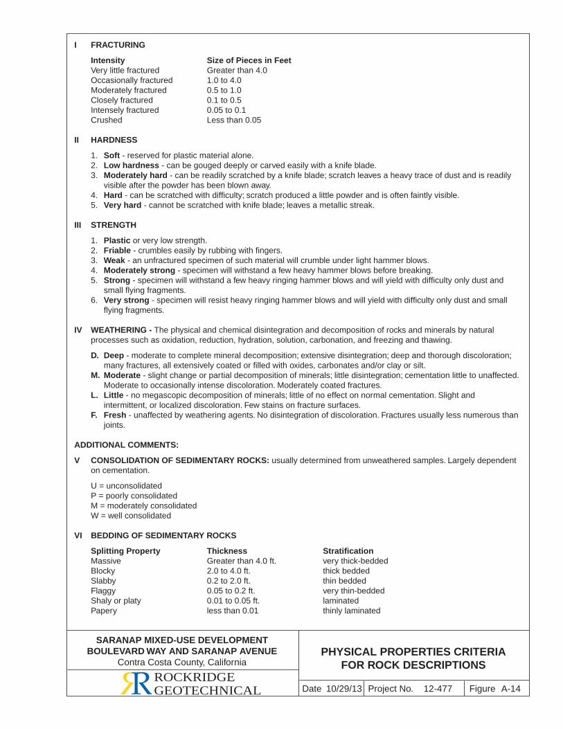
Project No. FigureDate A-14
PHYSICAL PROPERTIES CRITERIAFOR ROCK DESCRIPTIONS
I FRACTURING
Intensity Size of Pieces in Feet Very little fractured Greater than 4.0 Occasionally fractured 1.0 to 4.0 Moderately fractured 0.5 to 1.0 Closely fractured 0.1 to 0.5 Intensely fractured 0.05 to 0.1 Crushed Less than 0.05 II HARDNESS
1. Soft - reserved for plastic material alone. 2. Low hardness - can be gouged deeply or carved easily with a knife blade. 3. Moderately hard - can be readily scratched by a knife blade; scratch leaves a heavy trace of dust and is readily
visible after the powder has been blown away. 4. Hard - can be scratched with difficulty; scratch produced a little powder and is often faintly visible. 5. Very hard - cannot be scratched with knife blade; leaves a metallic streak.
III STRENGTH
1. Plastic or very low strength. 2. Friable - crumbles easily by rubbing with fingers. 3. Weak - an unfractured specimen of such material will crumble under light hammer blows. 4. Moderately strong - specimen will withstand a few heavy hammer blows before breaking. 5. Strong - specimen will withstand a few heavy ringing hammer blows and will yield with difficulty only dust and
small flying fragments. 6. Very strong - specimen will resist heavy ringing hammer blows and will yield with difficulty only dust and small
flying fragments.
IV WEATHERING - The physical and chemical disintegration and decomposition of rocks and minerals by natural processes such as oxidation, reduction, hydration, solution, carbonation, and freezing and thawing.
D. Deep - moderate to complete mineral decomposition; extensive disintegration; deep and thorough discoloration; many fractures, all extensively coated or filled with oxides, carbonates and/or clay or silt.
M. Moderate - slight change or partial decomposition of minerals; little disintegration; cementation little to unaffected. Moderate to occasionally intense discoloration. Moderately coated fractures.
L. Little - no megascopic decomposition of minerals; little of no effect on normal cementation. Slight and intermittent, or localized discoloration. Few stains on fracture surfaces.
F. Fresh - unaffected by weathering agents. No disintegration of discoloration. Fractures usually less numerous than joints.
ADDITIONAL COMMENTS:
V CONSOLIDATION OF SEDIMENTARY ROCKS: usually determined from unweathered samples. Largely dependent on cementation.
U = unconsolidated P = poorly consolidated M = moderately consolidated W = well consolidated
VI BEDDING OF SEDIMENTARY ROCKS
Splitting Property Thickness Stratification Massive Greater than 4.0 ft. very thick-bedded Blocky 2.0 to 4.0 ft. thick bedded Slabby 0.2 to 2.0 ft. thin bedded Flaggy 0.05 to 0.2 ft. very thin-bedded Shaly or platy 0.01 to 0.05 ft. laminated Papery less than 0.01 thinly laminated
10/29/13 12-477ROCKRIDGEGEOTECHNICAL
SARANAP MIXED-USE DEVELOPMENTBOULEVARD WAY AND SARANAP AVENUE
Contra Costa County, California
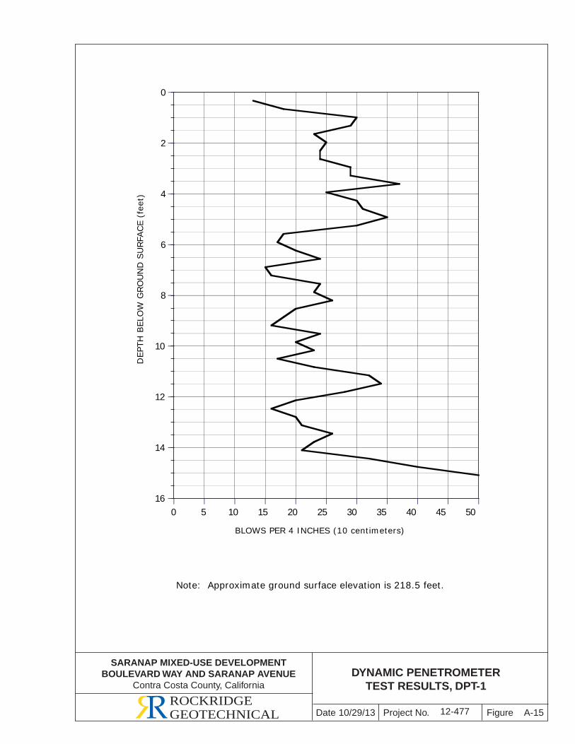
DYNAMIC PENETROMETERTEST RESULTS, DPT-1
Note: Approximate ground surface elevation is 218.5 feet.
A-15
DEP
TH B
ELO
W G
RO
UN
D S
URFA
CE
(fee
t)
16
14
12
10
8
6
4
2
0
0 5 10 15 20 25 30 35 40 45 50
12-477
BLOWS PER 4 INCHES (10 centimeters)
Project No. FigureDate 10/29/13ROCKRIDGEGEOTECHNICAL
SARANAP MIXED-USE DEVELOPMENTBOULEVARD WAY AND SARANAP AVENUE
Contra Costa County, California

APPENDIX B
Laboratory Test Results
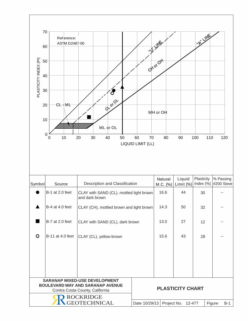
ML or OL
MH or OH
Symbol SourceNatural
M.C. (%)Liquid
Limit (%)
CL - ML
0
10
20
30
40
50
60
70
0 10 20 30 40 50 60 70 80 90 100 110 120
LIQUID LIMIT (LL)
Description and Classification% Passing#200 Sieve
PlasticityIndex (%)
Project No. FigureDate 10/29/13 B-1
PLASTICITY CHART
ROCKRIDGEGEOTECHNICAL
PLA
ST
ICIT
Y IN
DE
X (
PI)
Ref erence:ASTM D2487-00
12-477
SARANAP MIXED-USE DEVELOPMENTBOULEVARD WAY AND SARANAP AVENUE
Contra Costa County, California
B-1 at 2.0 feet
B-4 at 4.0 feet
B-7 at 2.0 feet
B-11 at 4.0 feet
CLAY with SAND (CL), mottled light brownand dark brown
CLAY (CH), mottled brown and light brown
CLAY with SAND (CL), dark brown
CLAY (CL), yellow-brown
16.6
14.3
13.0
15.6
--
--
--
--
44
50
27
43
30
32
12
28
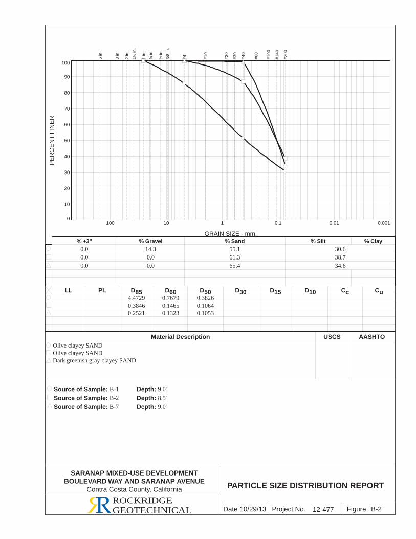
LL PL D85 D60 D50 D30 D15 D10 Cc Cu
Material Description USCS AASHTO
Source of Sample: B-1 Depth: 9.0'Source of Sample: B-2 Depth: 8.5'Source of Sample: B-7 Depth: 9.0'
4.4729 0.7679 0.38260.3846 0.1465 0.10640.2521 0.1323 0.1053
Olive clayey SANDOlive clayey SANDDark greenish gray clayey SAND
PER
CEN
T FI
NER
0
10
20
30
40
50
60
70
80
90
100
GRAIN SIZE - mm.
0.0010.010.1110100
% +3" % Gravel % Sand % Silt % Clay0.0 14.3 55.1 30.60.0 0.0 61.3 38.70.0 0.0 65.4 34.6
6 in
.
3 in
.
2 in
.
1½ in
.
1 in
.
¾ in
.
½ in
.
3/8
in.
#4 #10
#20
#30
#40
#60
#100
#140
#200
SARANAP MIXED-USE DEVELOPMENTBOULEVARD WAY AND SARANAP AVENUE
Contra Costa County, California
Project No. FigureDateROCKRIDGEGEOTECHNICAL 10/29/13 B-2
PARTICLE SIZE DISTRIBUTION REPORT
12-477
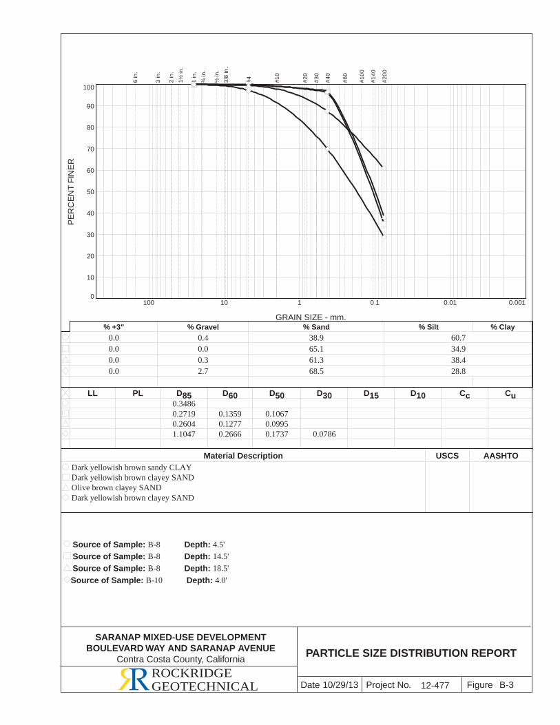
LL PL D85 D60 D50 D30 D15 D10 Cc Cu
Material Description USCS AASHTO
Source of Sample: B-8 Depth: 4.5'Source of Sample: B-8 Depth: 14.5'Source of Sample: B-8 Depth: 18.5'Source of Sample: B-10 Depth: 4.0'
0.34860.2719 0.1359 0.10670.2604 0.1277 0.09951.1047 0.2666 0.1737 0.0786
Dark yellowish brown sandy CLAYDark yellowish brown clayey SANDOlive brown clayey SANDDark yellowish brown clayey SAND
PER
CEN
T FI
NER
0
10
20
30
40
50
60
70
80
90
100
GRAIN SIZE - mm.
0.0010.010.1110100
% +3" % Gravel % Sand % Silt % Clay0.0 0.4 38.9 60.70.0 0.0 65.1 34.90.0 0.3 61.3 38.40.0 2.7 68.5 28.8
6 in
.
3 in
.
2 in
.
1½ in
.
1 in
.
¾ in
.
½ in
.
3/8
in.
#4 #10
#20
#30
#40
#60
#100
#140
#200
Project No. FigureDateROCKRIDGEGEOTECHNICAL
SARANAP MIXED-USE DEVELOPMENTBOULEVARD WAY AND SARANAP AVENUE
Contra Costa County, California
10/29/13 B-3
PARTICLE SIZE DISTRIBUTION REPORT
12-477
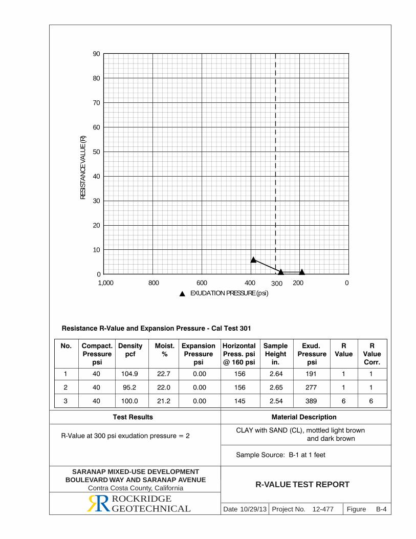
SARANAP MIXED-USE DEVELOPMENTBOULEVARD WAY AND SARANAP AVENUE
Contra Costa County, California
0
10
20
30
40
50
60
70
80
90
1,000 800 600 400 200 0
EXUDATION PRESSURE (psi)300
RESI
STA
NCE
VA
LUE
(R)
Project No. FigureDate B-4
R-VALUE TEST REPORT
ROCKRIDGEGEOTECHNICAL 10/29/13 12-477
Resistance R-Value and Expansion Pressure - Cal Test 301
No. Compact.Pressure
psi
Densitypcf
Moist.%
ExpansionPressure
psi
SampleHeight
in.
HorizontalPress. psi@ 160 psi
Exud. Pressure
psi
RValue
RValueCorr.
1
2
3
40
40
40
104.9
95.2
100.0
22.7
22.0
21.2
0.00
0.00
0.00
156
156
145
2.64
2.65
2.54
191
277
389
1
1
6
1
1
6
R-Value at 300 psi exudation pressure = 2CLAY with SAND (CL), mottled light brown and dark brown
Sample Source: B-1 at 1 feet
Test Results Material Description

SARANAP MIXED-USE DEVELOPMENTBOULEVARD WAY AND SARANAP AVENUE
Contra Costa County, California
RESI
STA
NCE
VA
LUE
(R)
0
10
20
30
40
50
60
70
80
90
1,000 800 600 400 200 0
EXUDATION PRESSURE (psi)
300
Project No. FigureDate B-5
R-VALUE TEST REPORT
ROCKRIDGEGEOTECHNICAL 10/29/13 12-477
Resistance R-Value and Expansion Pressure - Cal Test 301
No. Compact.Pressure
psi
Densitypcf
Moist.%
ExpansionPressure
psi
SampleHeight
in.
HorizontalPress. psi@ 160 psi
Exud. Pressure
psi
RValue
RValueCorr.
1
2
3
40
40
40
106.7
102.3
100.3
17.8
21.4
23.4
0.00
0.00
0.00
124
146
151
2.43
2.52
2.50
603
386
221
14
5
3
13
5
3
R-Value at 300 psi exudation pressure = 4CLAYEY SAND (SC), dark brown
Sample Source: B-10 at 1 feet
Test Results Material Description
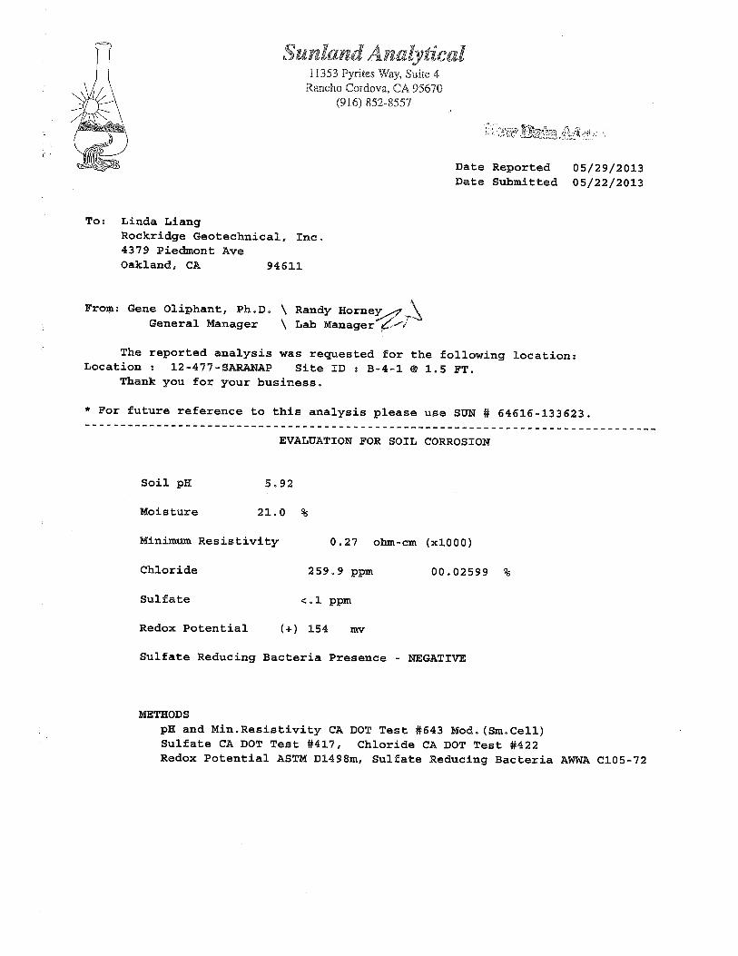
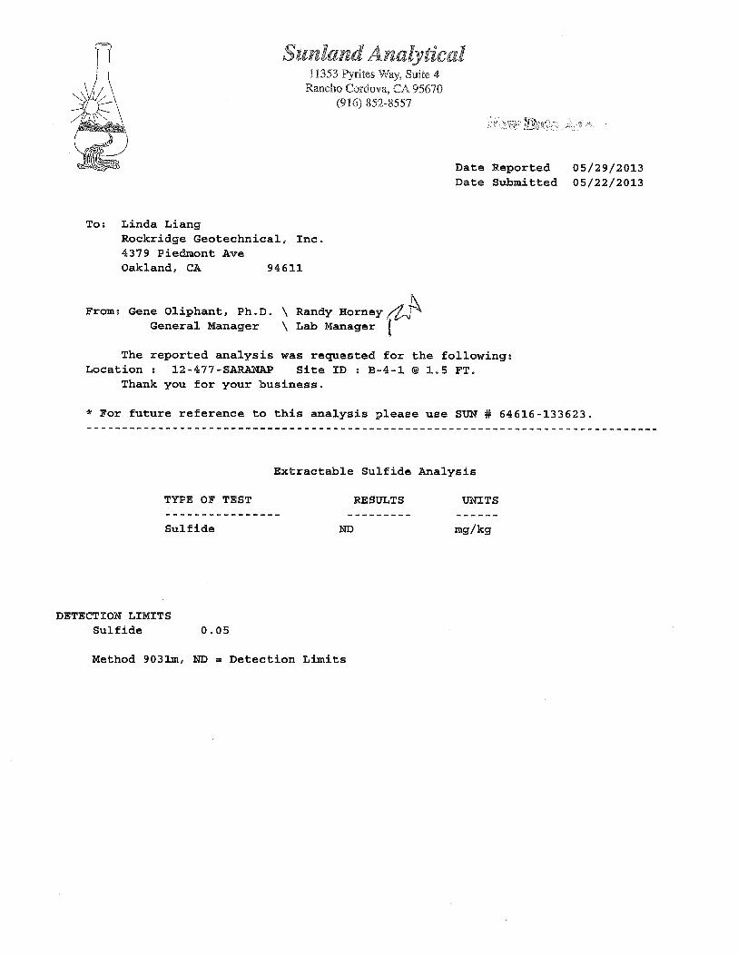
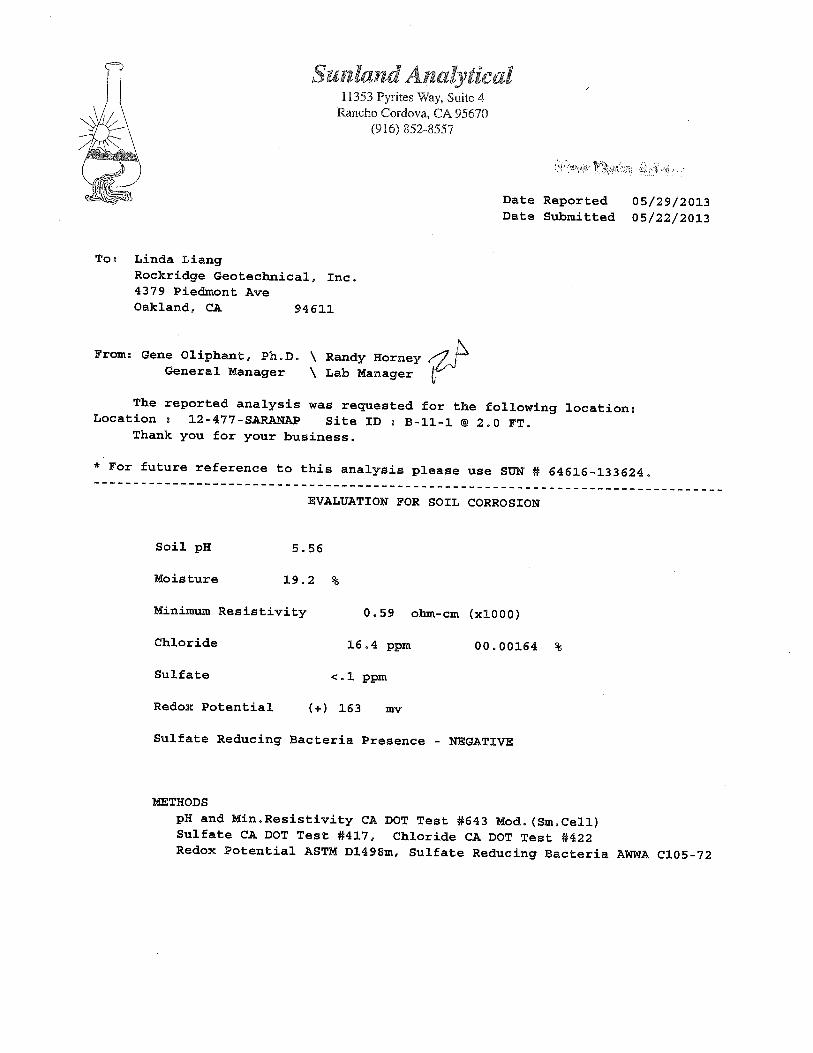
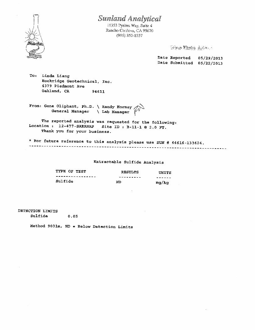
April 9, 2014 Project No. 12-477
Mr. Michael Smith Vice President/Forward Planner Hall Equities Group 1855 Olympic Boulevard, Suite 250 Walnut Creet, California 94596
Subject: Letter of Confirmation for Site B1 Saranap Mixed-Use Development Contra Costa County, California
Dear Mr. Smith,
This letter presents our conclusions regarding geotechnical information available for adequate and safe development at Site B1 of the Saranap mixed-use project in Contra Costa County, California. We previously performed a geotechnical investigation for the Saranap project, the results of which were presented in our report dated October 30, 2013.
Site B1 is located between Sites B and C and bordered by Site B to the east, Boulevard Way to the north, and Site C to the west. As part of our 2013 geotechnical investigation for the Saranap project, we drilled two soil borings, designated Borings B-6 and B-10. Boring B-1 was located at the northwest corner of Site B and Boring B-1 was located at the northeast corner of Site C. These two borings are in close proximity to Site B1.
We conclude our 2013 geotechnical investigation for the Saranap project provided sufficient information to develop conclusions and recommendations for the geotechnical aspects of the proposed development at Site B1. We also conclude that implementation of the recommendations we prepared for Sites B and C in our October 30, 2013 report will assure adequate and safe development at Site B1.
We trust that this letter provides you with the information you requested. If you have any questions, please call.
Sincerely yours, ROCKRIDGE GEOTECHNICAL, INC.
Linda H. J. Liang, P.E., G.E. Craig S. Shields, P.E., G.E. Senior Engineer Principal Geotechnical Engineer
April 10, 2014 Project No. 12-477
Mr. Michael Smith Vice President/Forward Planner Hall Equities Group 1855 Olympic Boulevard, Suite 250 Walnut Creet, California 94596
Subject: Sites A and B – Groundwater Design Alternatives Saranap Mixed-Use Development Contra Costa County, California
Dear Mr. Smith,
This letter presents our conclusions regarding groundwater design alternatives for the proposed development at Sites A and B of the Saranap mixed-use project in Contra Costa County, California. We previously performed a geotechnical investigation for the Saranap project, the results of which were presented in our report dated October 30, 2013.
On the basis of our geotechnical investigation, we recommended proposed buildings at Sites A and B be designed using design groundwater depths of 8 and 10 feet below the ground surface (bgs), respectively. Because of the relatively high groundwater table and the anticipated depth of excavation, design measures will need to be implemented for construction of basement levels at Sites A and B. We conclude feasible design measures to address groundwater consist of the following three alternatives:
Alternative 1: Fully waterproofed building with the basement walls and building foundation designed for hydrostatic pressure
Alternative 2: Install underslab drainage system and discharge groundwater to sewer system
Alternative 3: Install underslab drainage system and discharge groundwater to storm drain
For Alternative 1, we recommend the below-grade portion of the building be fully waterproofed and the building foundation and floor slab be designed to resist hydrostatic uplift force. Unbalanced hydrostatic uplift forces may be resisted by installing uplift anchors (tiedown anchors). Tiedown anchors will be installed within the footprint of the proposed basement and at the proposed basement elevation. There will be no substantial change in excavation associated with installation of tiedown anchors. Installation of tiedown anchors will generate drilling spoils that will need to be off-hauled; however, we conclude the amount of off-haul will not alter substantially the amount of off-haul for the entire project (off-haul for entire project estimated at 70,000 cubic yards).
Mr. Michale Smith
Hall Equities Group April 10, 2014 Page 2
Alternatives 2 and 3 consist of installing an underslab drainage system to eliminate hydrostatic pressure on the floor slab and foundations. The permanent dewatering system should consist of an at least 12-inch-thick layer of Class 2 permeable material containing parallel collection pipes spaced approximately every 20 feet, center-to-center. The collection pipes should be connected to at least one sump pit. The groundwater seeping beneath the building should be continuously collected in the sump and then pumped into the sanitary sewer system (Alternative 2) or storm drain (Alternative 3). The underslab system would be in lieu of grading and construction that would otherwise occur at the site, and would not result in a substantial difference in the amount of grading, excavation, off-haul, or material delivery to the site.
For both Alternatives 2 and 3, the sump pit will be located inside the basement footprint and extend slightly below the basement subgrade. For these alternatives, a back-up generator is generally needed to run the discharge pump inside the sump pit in case of a power failure. The emergency generators proposed for the project could be used for the sump pump, without any need to increase the size or number of generators.
Long-term discharge of water into the sanitary sewer or storm drain system will require a discharge permit from applicable governing agencies. The governing agencies may require laboratory testing of groundwater samples to evaluate the groundwater quality. Depending on the water quality test results, the governing agency may require the groundwater be treated (i.e. with carbon filter or other appropriate treatment systems) prior to discharge into the storm drain system. A groundwater treatment system, if required, may be located inside the footprint of the proposed basement.
We trust that this letter provides you with the information you requested. If you have any questions, please call.
Sincerely yours, ROCKRIDGE GEOTECHNICAL, INC.
Linda H. J. Liang, P.E., G.E. Craig S. Shields, P.E., G.E. Senior Engineer Principal Geotechnical Engineer