Embed Size (px)
Citation preview
Prepared by
LAKE communications ltd
by Inter-Tel

Contents
Section 1 Introduction
Section 2 Installation and Cabling
Section 3 User Operation and Features
Section 4 Programming
Section 5 System Hardware Description
Section 6 System Maintenance
Section 1Introduction to the Encore

• The Inter-Tel Encore is a modular, hybrid telephone system
• It can be equipped with Keysets and single-line telephones
• Optional built-in voice module
• Remote maintenance and programming

• Optional Battery Backup Unit
• Optional Doorphone
• Keyset TAPI Module (Call Manager)
• Optional Call Logging Interface
• Phase 2: Upgrade to Basic Rate ISDN Interfaces Up to 5 basic accesses. Max four network interfaces
and one internal ISDN BRI interface
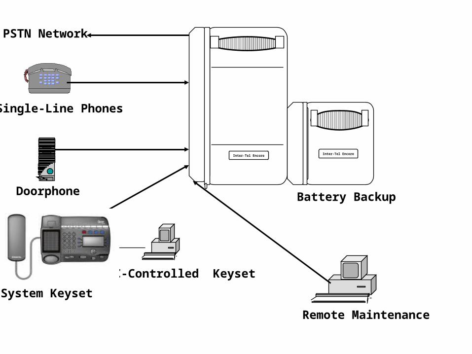
Inter-Tel Encore
PSTN Network
PC-Controlled Keyset
System Keyset
Doorphone
Remote Maintenance
Inter-Tel Encore
Single-Line Phones
Battery Backup

Standard Configurations
• 2 Loop Start Lines / 6 Extensions
• 4 Loop Start Lines / 12 Extensions
• 6 Loop Start Lines / 18 Extensions

Other Configurations
• 4 Loop Start Lines / 6 Extensions
• 6 Loop Start Lines / 12 Extensions
• 8 Loop Start Lines / 18 Extensions
These need an additional 2-Port Loop Start card added to Basic Configurations

Yet More Possible Configurations
• 2 Loop Start Lines / 12 Extensions
• 2 Loop Start Lines / 18 Extensions
• 4 Loop Start Lines / 18 Extensions
These need additional 6-Port Keyset card(s) added to Basic Configuration

1st Stage Expansion: Line Ports
Line cardLines 1& 2
Line cardLines 3 & 4
Line cardLines 1& 2
Line cardLines 3 & 4
PSU
1st Stage Configuration Options
• 2 Loop Start Lines & 6 Extensions
• 4 Loop Start Lines & 6 Extensions
6-Extension Base Board

2nd Stage Expansion: Extension Ports
PSTN cardC.O. 1& 2
PSTN cardC.O. 3 & 4
PSU
2nd Stage Configuration Options
• 4 Loop Start Lines & 12 Extensions
6 Extension ports
6 Extensions on CPU board
6 Extension ports

3rd Stage Expansion: Line Ports
PSTN cardC.O. 1& 2
PSTN cardC.O. 3 & 4
PSTN cardLines 5& 6
Line cardLines 5& 6
PSU
3rd Stage Configuration options
• 6 Loop Start Lines & 12 Extensions
6 Extensions on CPU board
6 Extension ports

4th Stage Expansion: Extension Ports
PSTN cardC.O. 1& 2
PSTN cardC.O. 3 & 4
Line cardLines 5 & 6
PSU4th Stage Configuration Options
• 6 Loop Start Lines & 18 Extensions
6 Extension ports
6 Extension ports 6 Extension ports
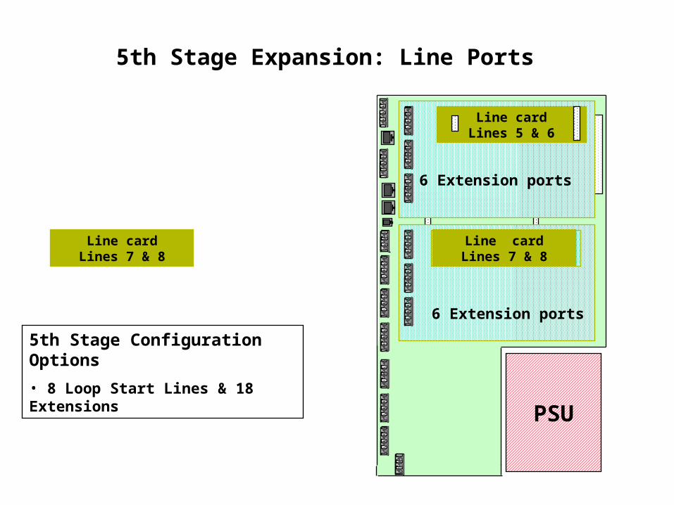
5th Stage Expansion: Line Ports
PSTN cardC.O. 1& 2
PSTN cardC.O. 3 & 4
Line cardLines 5 & 6
Line cardLines 7 & 8
Line cardLines 7 & 8
PSU
5th Stage Configuration Options
• 8 Loop Start Lines & 18 Extensions
6 Extension ports
6 Extension ports
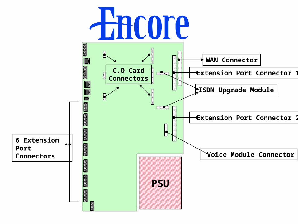
PSU
WAN Connector
Extension Port Connector 1
Extension Port Connector 2
C.O Card Connectors
ISDN Upgrade Module
Voice Module Connector
6 Extension Port Connectors
Section 2Installation and Cabling

• Maximum power consumed is 75 Watts
• Use a grounded power supply
• KSU is equipped with three-prong, grounded power cable
• KSU to be located within 6 feet of power outlet

–Krone IDC Punch Tool
–Slotted-tip screwdrivers 5.5mm X 10mm
– Electric drill with 6mm drill bit
• A standard tool kit should include:
Required Tools

KSU Mounting Bracket
4.8 in. (120mm)clearance
20 in.(500mm)
60 in.(1500mm)
20 in.(500mm)
clearance

Locate the mounting bracket in asuitable position and place the KSU onto it by lowering it into position
Retaining screw for MDF cover
Remove the MDF cover bysliding upwards
Inter-Tel Encore
Mounting the KSU

Inter-Tel Encore
Two retaining screws
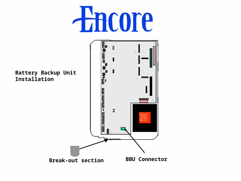
Break-out section
SYSTEM MUST BE
DISCONNECTED
FROM MAINS
SUPPLY BEFORE
REMOVING LID
2
BBU Connector
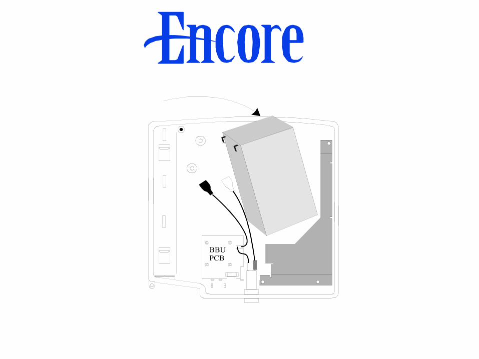
Battery Backup UnitInstallation

2.4 in.
(60mm)
4.8 in.
(120mm)
Clearances shown apply if Battery Backup Unitis placed to the right of, or underneath, the KSU

• Always use electrostatic protection when inserting and removing circuit boards
• Never insert or remove circuit boards when power is applied to the system
Caution
6-Port Keyset Card
• Six extension circuits
• Provides connectors for two lines
• Connector for the 2-Port Loop Start Card
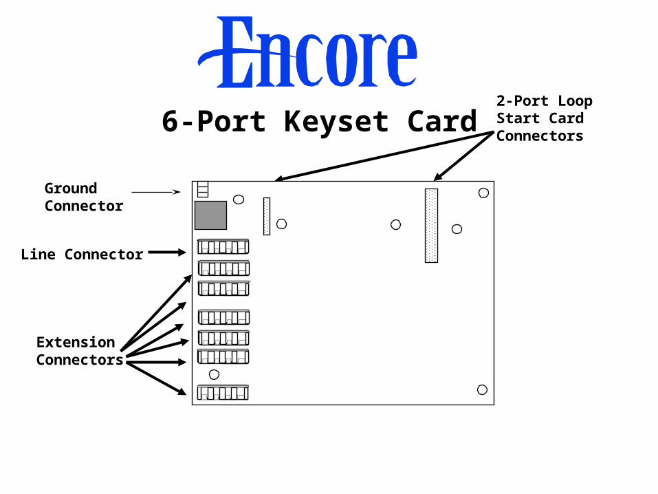
GroundConnector
ExtensionConnectors
Line Connector
2-Port Loop Start CardConnectors
6-Port Keyset Card
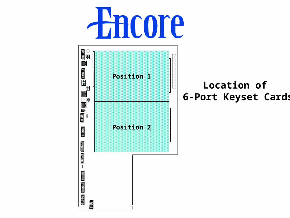
Location of 6-Port Keyset Cards
Position 2
Position 1

Column Support for 6-Port Keyset Card

2-Port Loop Start Card
• Supports two lines
• Can be located on the CPU Card
• Can also be located on the 6-Port Keyset card
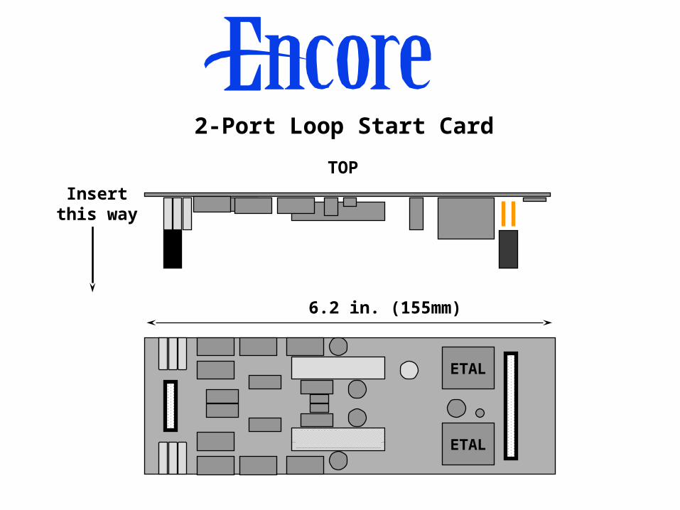
Insertthis way
ETAL
ETAL
TOP
6.2 in. (155mm)
2-Port Loop Start Card

2-Port Loop Start Card Locations
Locate Line cardhere
Locate Line cardhere
Locate Line cardhere
Locate Line cardhere

• Provides Voice Messaging
• Provides Auto-Attendant Service
• Provides Personalized Courtesy Service Greetings
Voice Module

4.4 in. (110mm)
3 in. (75mm)
Voice Module
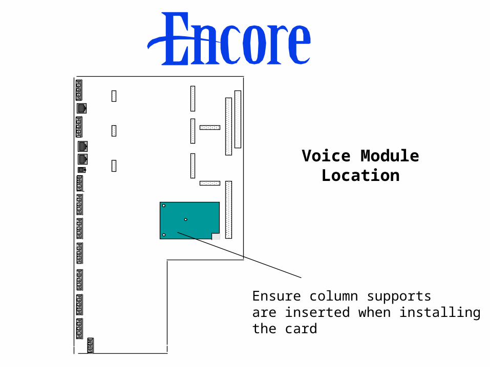
Voice Module Location
Ensure column supportsare inserted when installingthe card
• All line & extension connections to the Inter-Tel Encore are terminated in the MDF area of the main KSU
• The MDF area is accessed by removing the first-stage access cover on the main KSU housing
Cabling

Encore
MDF Area

Additional break-outscan be found alongthe left side of thecase.
Cable access via break-outpanel on bottom left of KSU housing.

A- Speech
B- Speech
C- Signaling
D- Signaling
Extension Termination4-Wire IDC Krone connector
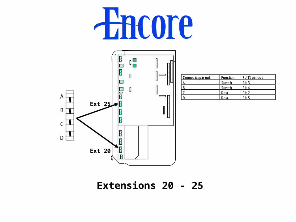
Extensions 20 - 25
Connector pin-out Function RJ 11 pin-outA Speech Pin 3B Speech Pin 4C Data Pin 2D Data Pin 5
Ext 20
Ext 25A
B
C
D

PSTN ExpansionCard
PSTN ExpansionCard
Extensions 26-37
A BC D 6-Port Keyset expansion cardsExt 26
Ext 31
Ext 32
Ext 37
A BC D

LINE 1
LINE 2 2-Port Loop StartCard
LINE 3
LINE 4
2-Port Loop Start Card
Lines 1, 2, 3, and 4
A
B
C
D
A
B
C
D

PSTN ExpansionCard
PSTN ExpansionCard
Lines 5, 6, 7, and 8
A BC D
LINE 5 LINE 6
2-Port Loop StartCard
2-Port Loop StartCard
6-Port Keyset expansion cards
A BC D
LINE 7 LINE 8

Power Fail Lines• Line 1 goes to Extension 24
• Line 2 goes to Extension 25
• Line 5 goes to Extension 31
• Line 7 goes to Extension 37
These extensions must be equipped with, or have access to, single-line phones

Central BellConnection
To the bell
A
B
C

A
B
External MusicOn Hold
To the Source
Fixed-screw terminal

Extension 23Doorphone
To the Doorphone
A
B
C
D

Doorstrike Connection
To theDoorstrike
A
B
C

A protective ground is connected to the grounding connectors on the CPU and 6-Port Keyset cards
Protective Ground

To Printeror PC
To RJ22 connectoron main board
socket 8
V24 Module & Serial Cable

BT InspirationV24 Module & Serial cable
RJ 22
Call Logging V24 Connection
Note: Also for programming from PC
Re-Attaching the KSU Cover• When installation is complete, the KSU cover is
re-attached• Where new cards have been installed the KSU
cover may no longer fit• There are break-out panels on the side of the KSU
cover which can be removed before re-attaching the lid

Break-out sections onKSU cover
Encore
• Fully handsfree• Four-line display• Six Display Keys for feature activation• Four Group Function keys• Eight Programmable keys • Can be connected to a PC running Call Manager
Keyset
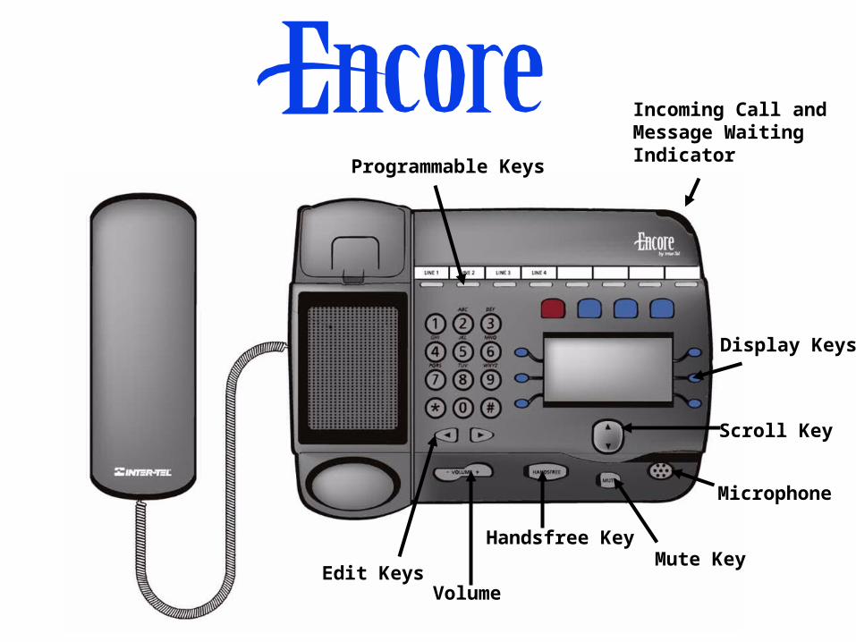
Programmable Keys
Incoming Call and Message Waiting Indicator
Display Keys
Microphone
Mute Key
Scroll Key
Handsfree Key
Volume Edit Keys

The Keyset baseplate allows the phone to be set at two different angles

6.32 in. (158mm)
Locate the two mounting screws 6.32 in. (158mm) apart and slide the Keyset down onto them by aligning the screw head retaining holes correctly
Wall Mounting the Keyset

Doorphone• Connected to Extension 23
• Can call specific groups of extensions
• Can be used with a Doorstrike to allow system controlled door access
• Programming required for Doorphone to operate
Note: The Doorstrike is not provided with Inter-Tel Encore

Mounting Screw
Doorphone Bracket

Call Manager
• Allows a PC to control a Keyset
• PC software supplied for customer installation
• 5VDC transformer supplied that connects to the Keyset

DC L2 TAPI L1
COM Port
AC to DC transformerOutput voltage is 5 Volts
V24 Call ManagerTAPI module
Inter-Tel EncoreKeyset
Customer PC
Serialcable
AC
DC
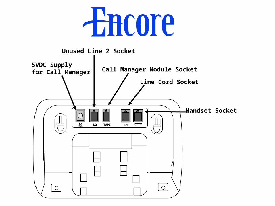
DC L2 TAPI L1
5VDC Supplyfor Call Manager
Unused Line 2 Socket
Call Manager Module Socket
Line Cord Socket
Handset Socket

Section 3User Operation and Features

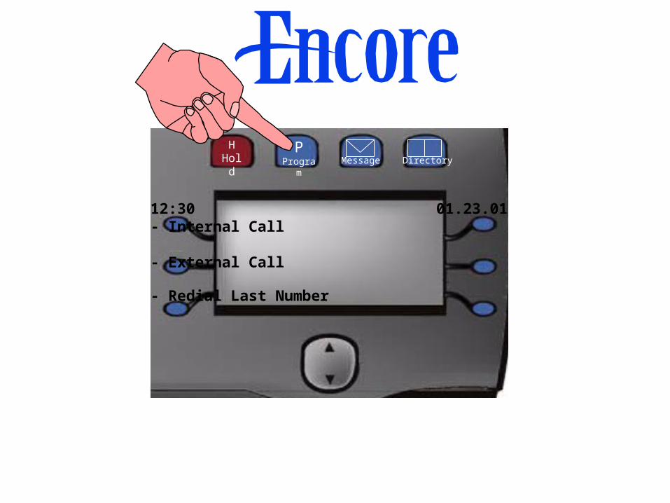
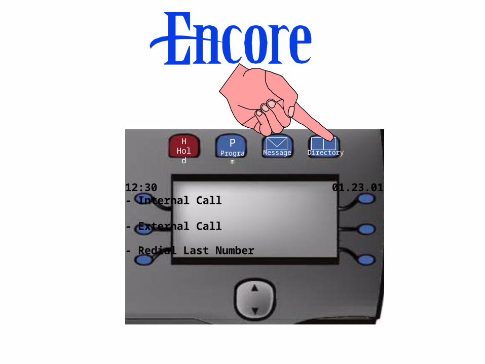
HHold
PProgram Message Directory
12:30 01.23.01- Internal Call
- External Call
- Redial Last Number
HHold
PProgram Message Directory
12:30 01.23.01- Internal Call
- External Call
- Redial Last Number

Phone Setup
-----PHONE SETUP----
- Language
- Personal Speed Dial
- Handsfree Answer
Screen 1
-----PHONE SETUP----
- Key Programming
- Headset Mode
- Ringing Options
Screen 2
-----PHONE SETUP----
- Contrast Options
- System Programming
- Cancel
Screen 3

Phone SetupLanguage
• English, Spanish or French• Each Keyset user can choose a language
Personal Speed Dial• 12 numbers and names• 24 digits and 10 letters per entry
Handsfree Answer•Automatically answer internal calls
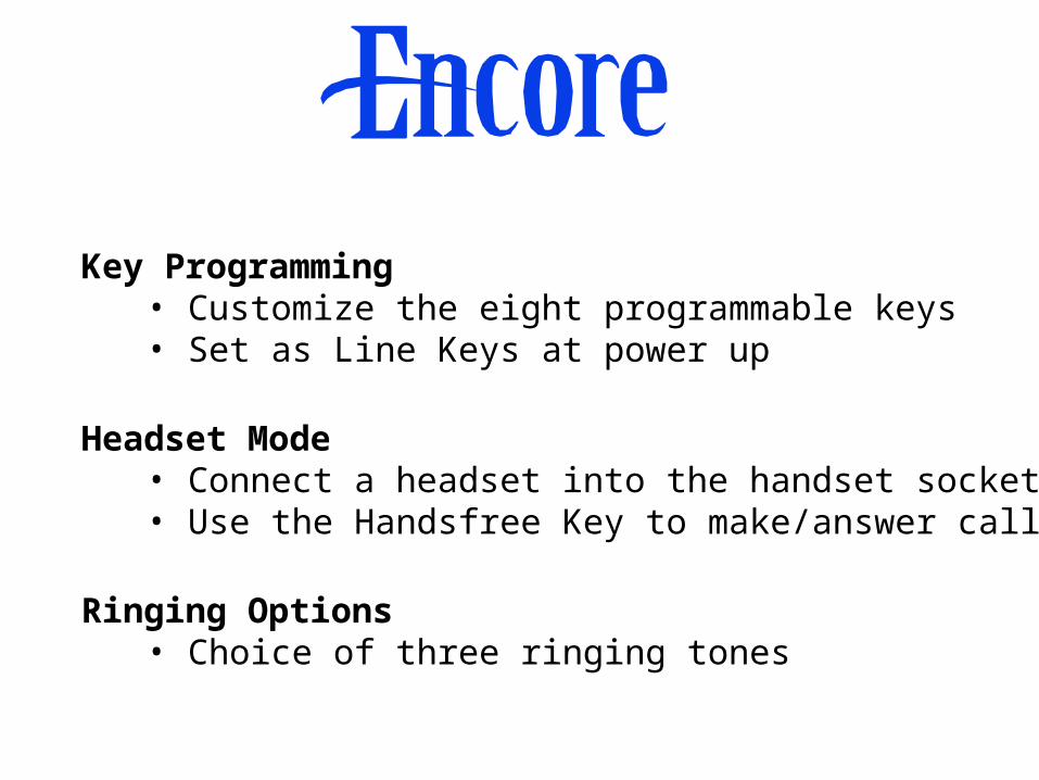
Key Programming• Customize the eight programmable keys• Set as Line Keys at power up
Headset Mode• Connect a headset into the handset socket• Use the Handsfree Key to make/answer calls
Ringing Options• Choice of three ringing tones

Contrast Options• Choice of four levels of display contrast
System Programming• Available to extension 20 at power up

HHold
PProgram Message Directory
12:30 01.23.01- Internal Call
- External Call
- Redial Last Number

Select Option
- Display Messaging
- Voice Messaging
- Cancel
Display Messaging• One of nine preset messages and one programmable message can be set
• This message is relayed to other keysets calling the phone
• The user can enter times, dates, or phone numbers, as required, in all the messages

• When selected access is gained to the Voice Message Box
• You are prompted for the extension number and password
• Password is 1111in default.
• A # must be entered after the password.
Voice Messaging
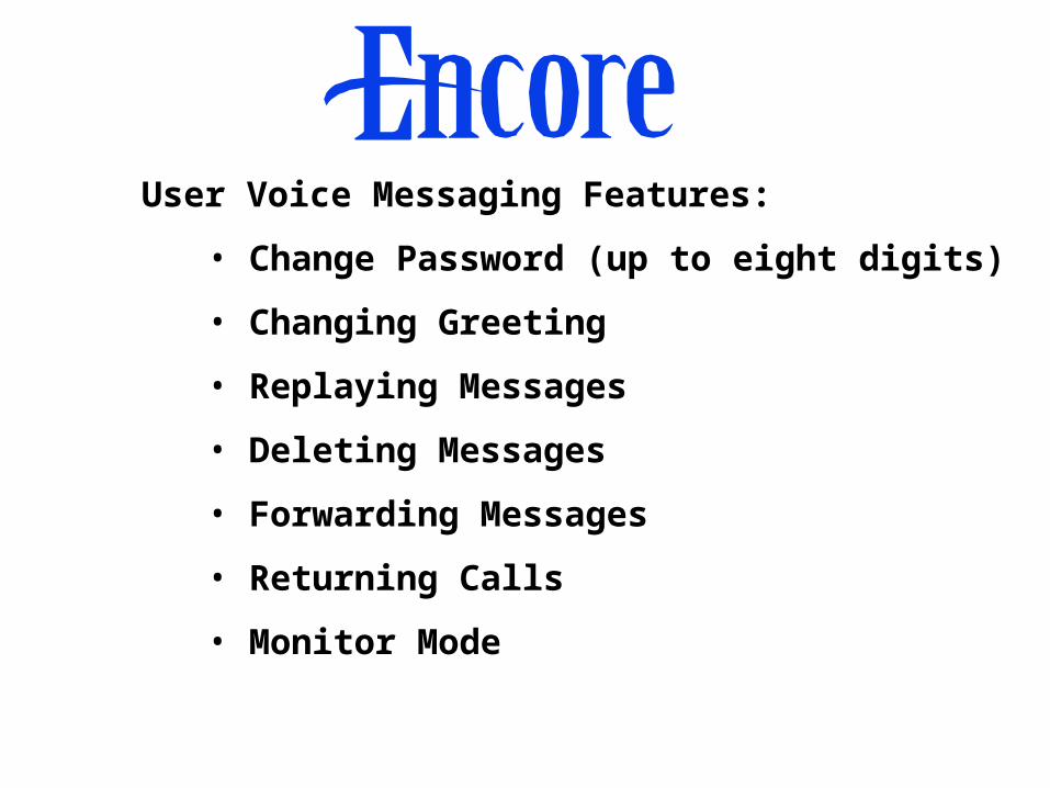
User Voice Messaging Features:
• Change Password (up to eight digits)
• Changing Greeting
• Replaying Messages
• Deleting Messages
• Forwarding Messages
• Returning Calls
• Monitor Mode
HHold
PProgram Message Directory
12:30 01.23.01- Internal Call
- External Call
- Redial Last Number

Select Option
-Personal Speed Dial
-System Speed Dial
-System Sales
Select Option
-System Service
-Cancel
Personal Speed Dial• Access to the 12 number/name Personal Speed Dial list. Numbers are dialed here. They are programmed under the P(Program) key

System Speed Dial
• Access to the 200 number/name system Speed Dial list.
System Sales• The System supplier’s Sales number is accessed
here. It is programmed in system programming.
System Service• The System supplier’s Service number is accessed here. It is programmed in system programming.
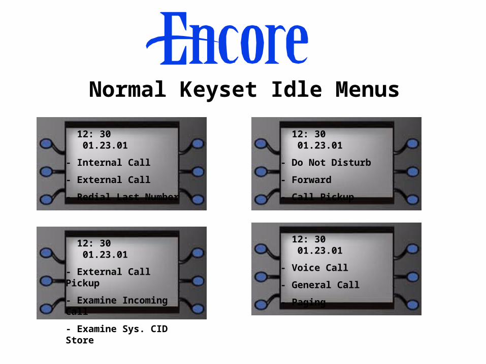
Normal Keyset Idle Menus
12: 30 01.23.01
- Internal Call
- External Call
- Redial Last Number
12: 30 01.23.01
- Do Not Disturb
- Forward
- Call Pickup
12: 30 01.23.01
- External Call Pickup
- Examine Incoming Call
- Examine Sys. CID Store
12: 30 01.23.01
- Voice Call
- General Call
- Paging

Normal Keyset Idle Menus
12: 30 01.23.01
- Extension Lock
- Reminder Call
- Reset The Phone
12: 30 01.23.01
- Room Monitor

Additional Idle Prompts
• Extension 20, the Operator Position, has Night Service, Hunt Group Forwarding, and, if a Voice Module is installed, Answering Machine added to the idle menu.
• If individual Caller ID Store lists are programmed for an extension, then Examine Caller ID Store is added to the idle Menu of the extension.

• Additional prompts are added to the top of the display when some features are activated on the Phone:
– Cancel Forwarding
– Cancel Lock
– Cancel Do Not Disturb
– Cancel Display Messaging
– New Voice Messages
– Examine Caller ID Store

• Other prompts are added to the top of the display on ALL phones when some system features are activated:
– Pick Up Park
– Answer Page
– Night Service

Making Internal Calls
• Go off hook and dial extension number (20-37)
• Enter extension number and then go off hook
• Select Internal Call on the display
Dial or Select Ext
Ext 20 Ext 23
Ext 21 Ext 24
Ext 22 Ext 25

Extension 24
-Ring Back
-Cancel
Phone Ringing
Busy
-Ring Back
-Call Waiting
-Cancel
Phone Busy
Stay off hook to
Camp On

Extension 24
-Internal Transfer
-External Transfer
-Internal Conference
Phone Answers
Extension 24
-External Conference
-Internal Consultation
-External Consultation
Extension 24
-Tone Protect
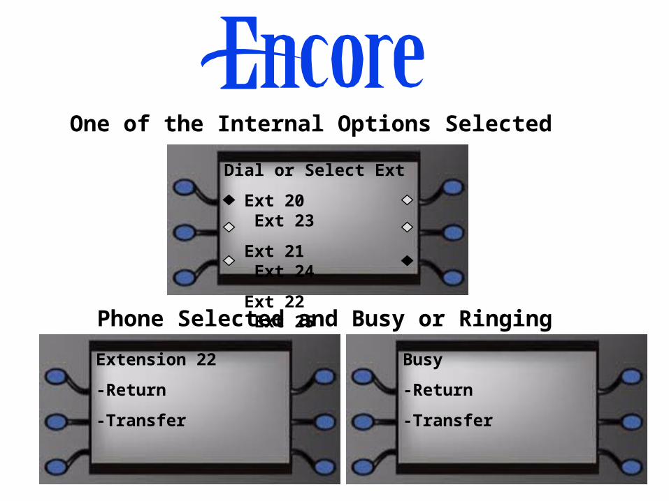
One of the Internal Options Selected
Extension 22
-Return
-Transfer
Phone Selected and Busy or Ringing
Dial or Select Ext
Ext 20 Ext 23
Ext 21 Ext 24
Ext 22 Ext 25
Busy
-Return
-Transfer

Second Phone Answers
Extension 22
-Return and Release
Extension 22
-Transfer
-Conference
-Return and Hold

Conference Selected
Conference
-Release First Call
-Release Second Call
-Exit Conference

One of the External Options Selected
4567890
-Return
-Cancel
Line Selected and Number Dialed
Dial or Select Line
Line 1 Line 4
Line 2 Cancel-
Line 3

External Call in Connected Phase
4567890
-Transfer
-Conference
-Return and Hold
4567890
-Return and Release

Call Ringing a Keyset
Extension 32
-Answer The Call
-Forward The Call
-Forward To Voice Msg
Forward To Voice Message is shown only if the extensionis equipped with a Voice Message Box
234567890
-Answer The Call
-Forward The Call
-Forward To Voice Msg

4567890
-System Hold
-Internal Transfer
-External Transfer
External Call Answered
4567890
-Internal Conference
-External Conference
-Internal Consultation
4567890
-External Consultation
-Call Park
-Tone Protect

Placing a Call On Hold• When an external call is answered, press the Hold Key or select System Hold
• Line Key LED flashes (a programmable option is available where the LED is steady)
4567890
-Return To Call
-Internal Call
-External Call
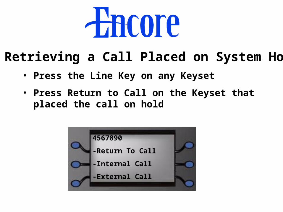
Retrieving a Call Placed on System Hold• Press the Line Key on any Keyset
• Press Return to Call on the Keyset that placed the call on hold
4567890
-Return To Call
-Internal Call
-External Call

Features Invoked From Idle
Last Number Redial• The last external number dialed is redialed.
Do Not Disturb• Busy tone returned to all internal callers. “Do Not disturb” is displayed on the Keyset making the call.
Call Forwarding• Provides four types of call forwarding:
– Forward All Calls- All calls are forwarded to a programmed number.
– Forward On No Answer - Forwards calls which are ringing for a programmable time.
– Forward on Busy - Forwards calls when the phone is busy.
– Follow Me - You can set up All Call forwarding from the receiving extension
• Calls can be forwarded to internal or external numbers
• Internal calls are NOT forwarded to external numbers
• Forward to extension 38 to forward calls to Voice Messaging

Call Pickup
• Extensions in a Pickup Group can answer each others calls
• Up to four groups can be programmed
• Using External Call Pickup, any extension can answer an external call
Examine I/C Call• You can Examine the Caller ID Information of an external call ringing on other phones

Examine System Caller ID Store• You can access the system Caller ID Store list
• You can Redial numbers in the list
• Redialed numbers are indicated with an “R”
• All calls or unanswered calls can be stored
• Answered calls are indicated with an “A”
• The time the call was received is displayed
• Pressing the right Edit key displays the date

Voice Call (Intercom)• Place a call to an extension which is relayed over the speaker of the called Keyset.
General Call• When selected all phones in the General Call group are rung. All phones are in the group at power up.
Paging (Two Options)• Page all Keysets
• Page over external paging, if equipped

Extension Lock• Each extension user can lock the phone so that a password must be entered to make an external call
• Each user can program his or her own password
• Password is 123 at Power Up
Reminder Call• Program the phone to ring a a particular time

Reset the Phone• This cancels the following features, if set, on the phone:
– Do Not Disturb
– Call Forwarding
– Reminder Call
– Display Messaging
– Ring Back
Room Monitor• When set on a phone, extensions 20 and 21 can dial the number and listen over the handset.

• The number/name of the caller is displayed on the Keyset
• Calls can be routed to specific extensions based on the incoming Caller ID number
• The system can store 65 calls records • The system can associate up to 30 names with Caller ID numbers • Up to 12 extensions can have individual Caller ID stored lists of five numbers each
Caller ID Features

Call Logging
When enabled the output is:1 2 3 4 5 6 7 8 9O/G 10/01/99 12.00:01 00:00:30 L01 S21 S21 :000.00 1234567O/G 10/02/99 12.00:10 00:01:56 L02 S25 S25 :000.00 567890I/C 10/13/99 12.01:13 00:06:32 L03 S22 S24 :000.00
Column Number Data Output Explanation 1 Incoming (I/C) or Outgoing (O/G) Call2 Date (day/month/year)3 Start Time4 Duration of the call5 Line Used6 Initiating Extension7 Terminating Extension8 Cost9 Digits Entered (outgoing calls only)

• Connection V24 / RS 232- Bit Rate: 4800, 9600, or 19200 bps
- Data: 8 Bits
- Parity: None
- Stop Bits: One
V24 Module
Hot Line• Phones can be programmed so that they
automatically dial a number when they go off hook. This can be an extension, an external number, a line access digit, or a partial number.
Hunt Groups
• Group hunting allows you to have groups of extensions answering incoming calls. The calls to the group are circulated in cyclical order. Calls are evenly distributed in the group.
• Forwarding of hunt group calls is set up by extension 20.

Night Service
• Can be set from extension 20, as required
• Can be programmed to turn on automatically
• Different phones can be programmed to ring for incoming calls
• Each extension can be placed in a different Class of Service than in day mode
• Weekend Service allows Night Service to remain activated over weekends
Courtesy Service• Calls ringing for a period are answered by a
voice message. Callers are told that the call will
be answered
• This is a standard feature on all units

Voice Module Features• Individual Voice Message Boxes
• System Answering Machine
• Remote Access
• Auto Attendant
• Customized Courtesy Greeting
• Up to 80 Minutes Storage
• Dual-Port Module

Individual Voice Message Boxes• Each extension can be allocated a box
• Forward to 38 to activate it
• Waiting messages indicated by the Message
light on the Keyset
• Text prompt on the display shows “New Voice
Messages”
• Selecting the associated key accesses the
message box

System Answering Machine• Turned on at extension 20
• Lines on which it operates are selected in
programming
• Use extension number “0” to access it from any
extension
• Programmable ringing timer
• You can dial through to extensions

Remote Access to Voice Messaging• Dial through Answering Machine or Auto
Attendant
• Direct access based on Caller ID
• Dial 88 followed by extension number,
password, and #
• Dial codes are also used by single-line
telephones
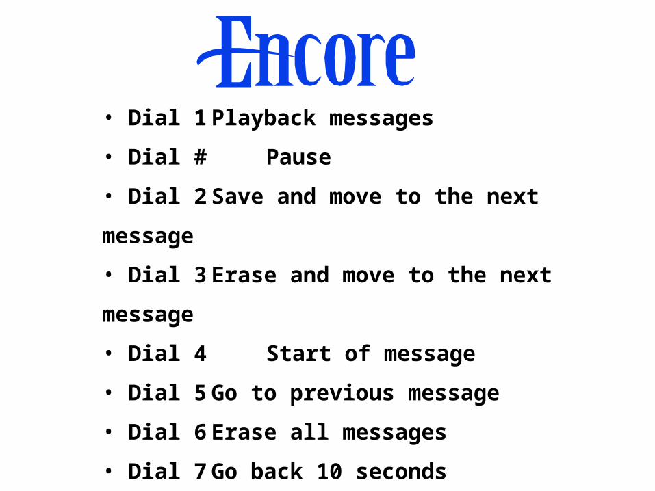
• Dial 1 Playback messages
• Dial # Pause
• Dial 2 Save and move to the next message
• Dial 3 Erase and move to the next message
• Dial 4 Start of message
• Dial 5 Go to previous message
• Dial 6 Erase all messages
• Dial 7 Go back 10 seconds
• Dial 8 Go forward 10 seconds

• Dial 9 Forward message
• Dial 0 Return call
While listening to the Greeting:
• Dial 91 Change greeting
• Dial 92 Check greeting
• Dial 93 Delete greeting
• Dial 0 Change password
Feature Operation
from Single-Line Telephones• All features accessible by dialing feature
codes
• Use hookflash when on a call
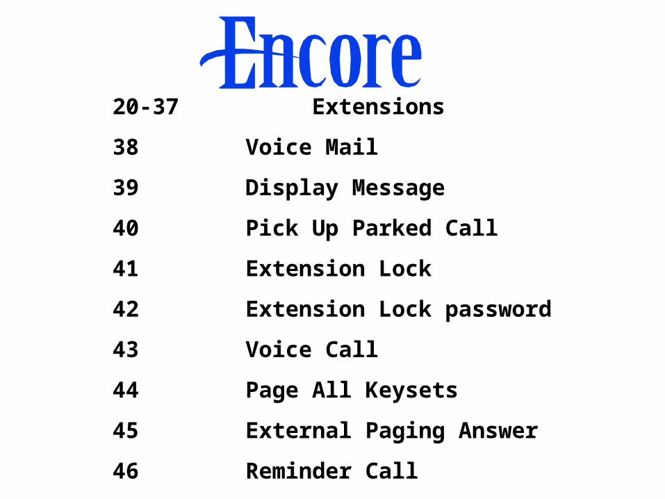
20-37 Extensions
38 Voice Mail
39 Display Message
40 Pick Up Parked Call
41 Extension Lock
42 Extension Lock password
43 Voice Call
44 Page All Keysets
45 External Paging Answer
46 Reminder Call

46* Cancel Reminder Call
47 Paging Call
48 Room Monitor
49(0,1,2) Remote Maintenance Codes
51-58 Individual Line Access
60 Redial
61 Personal Speed Dial Access
62 Personal Speed Dial Program
65 General Call

66 Tone Protection
67 Call Pick Up External
68 Call Pick Up Group
7001-7200 System Speed Dials
81-83 Line Groups
86 Operate Doorstrike
88 Retrieving Voice Messages
9 Line Access
0 Extension 20, Operator

150 Do Not Disturb Set/Cancel
151 Call Forward All Calls
152 Call Forward When Busy
153 Call Forward On No Answer
154 Follow Me
156 Night Service On/Off
157 Phone Reset
158 Answering Machine On/Off

Hookflash System Hold
Hookflash 1 Return and Release
Hookflash 2 Return and Hold
Hookflash 3 Conference
Hookflash 5 Ring Back
Hookflash 8 Send Call Waiting
Hookflash 40 Call Park
Hookflash 66 Tone Protection
Hookflash 87 Forward Recall

Section 4
Programming

• Select System Programming at extension 20
• Enter Default password: 1111
Select Option
- System
- Extensions
- Lines

Select Option
- Time and Date
- Language
- Change Password
System Programming Screen 1
• Time and Date: Allows Time and Date to be modified
• Language: English, French, or Spanish for all phones
• Change Password: Change four-digit programming password

Select Option
- Programming Position
- System Speed Dial
-Night Service
System Programming Screen 2
• Programming Position: Change to another extension
• System Speed Dial: 200 entries of numbers and names with 24 digits and 10 letters per entry

• Night Service: Has two options.
– Automatic Service - Set an on and off time
– Weekend Service - Select on or off (Night Service stays on for the weekend when set)
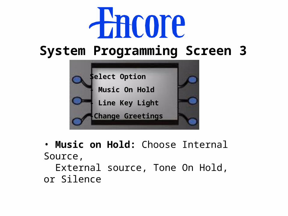
Select Option
- Music On Hold
- Line Key Light
-Change Greetings
System Programming Screen 3
• Music on Hold: Choose Internal Source,
External source, Tone On Hold, or Silence

• Line Key Light: Line Key flashing or steady for calls on system Hold
• Change Greetings: Record greetings when Voice Module is installed.
– Auto Attendant day, Auto Attendant night
– Courtesy Service day, Courtesy Service night
– Directory

Select Option
- Call Logging
- Timers
- Doorphone
System Programming Screen 4
• Call Logging: Select on or off for the system
• Doorphone: Doorphone equipped or not
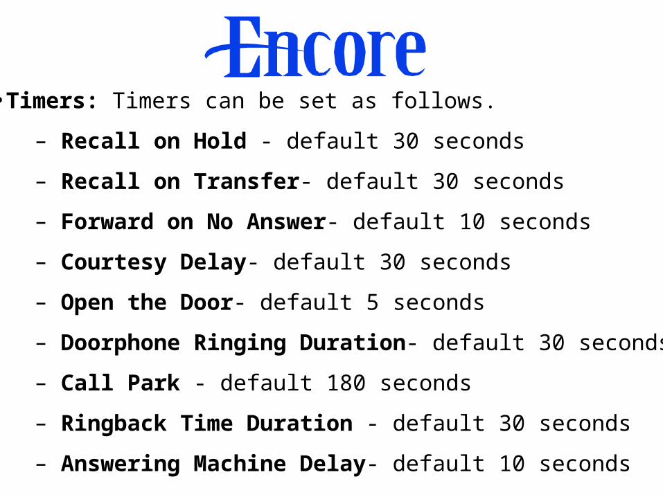
•Timers: Timers can be set as follows.
– Recall on Hold - default 30 seconds
– Recall on Transfer- default 30 seconds
– Forward on No Answer- default 10 seconds
– Courtesy Delay- default 30 seconds
– Open the Door- default 5 seconds
– Doorphone Ringing Duration- default 30 seconds
– Call Park - default 180 seconds
– Ringback Time Duration - default 30 seconds
– Answering Machine Delay- default 10 seconds
Select Option
- PA Amplifier
- CID Store
- Class Codes
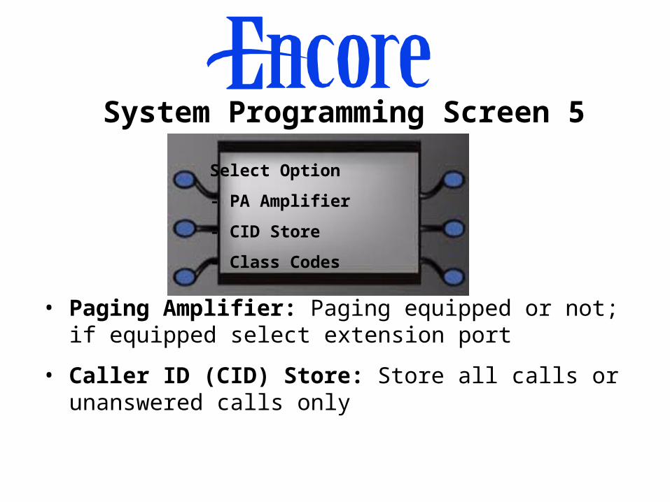
System Programming Screen 5
• Paging Amplifier: Paging equipped or not; if equipped select extension port
• Caller ID (CID) Store: Store all calls or unanswered calls only

• Class Codes:
– Four tables of codes (Tables 2, 3, 5, and 6)
– Each table has 50 entries of 13 digits each
– Entries in Table 2 are restricted to extensions placed in Class 2
– Entries in Table 3 are restricted to extensions placed in Class 3
– Entries in table 5 are allowed codes and can be combined with Classes 2 and 3
– Entries in Table 6 are restricted codes and
can be combined with Classes 1, 2, and 3

Select Option
- Local Codes
- Reset options
- Voice Box Ports
System Programming Screen 6
• Local Codes:
– Table of 40 entries of 3 digits each
– To enable numbers to be correctly stored in the Caller ID stores, digit 1 is added to toll calls

• Reset: There are two reset options.
• Warm Reset: Programming data is retained
• Full Reset: System is defaulted and all programming is lost
• Voice Message Box Ports: Select extensions on Ports 1 and 2 of the Voice Module.

Select Option
- Set V24 Baud Rate
- Sales / Service Numbers
- Cancel
System Programming Screen 7
• Set V24 Baud Rate: Speed of V24 output can be set to 4800, 9600, or 19200 bps
• Sales/Service Numbers: Program the numbers for Sales and Service under the Directory key
Select Option
- Name Programming
- Restriction Classes
- Tone Protect
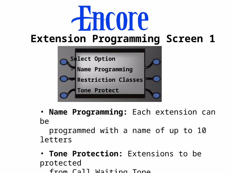
Extension Programming Screen 1
• Name Programming: Each extension can be programmed with a name of up to 10 letters
• Tone Protection: Extensions to be protected from Call Waiting Tone

• Restriction Classes: Each extension is allocated a
Class of Service
– At default all are in Class 1 (No Restriction)
– Class 2 is restricted from dialing codes in Table 2
– Class 3 is restricted from dialing codes in Table 3
– Class 4 is emergency calls (911) only
– Table 5, allowed codes, can be combined with Classes 2 and 3
– Table 6, restricted codes, can be combined with Classes 1, 2, and 3

Select Option
- Page Protection
- General Call Protection
- Open Door Restrict
Extension Programming Screen 2
• Page Protection: Program the extensions that are not to be paged

• General Call Protection: Program the extensions that are not rung for a General Call
• Open Door Restrict: Program the extensions that are not allowed to open the door using the Doorstrike

Select Option
-Pick Up Groups
-Individual CID Stores
-Sys Speed No Override
Extension Programming Screen 3
• Pick Up Groups: Four groups of extensions can be programmed. Extensions can only be in one group.

• Individual Caller ID (CID) Stores: Program the extensions that will have individual Caller ID stored lists
– Five numbers per stored list
– Maximum of 12 individual stored lists
– Total capacity 65 store lists system-wide
• System Speed Number Override: Program the extensions that are allowed to access all numbers in the system directory regardless of their Class of Service

Select Option
- Voice Boxes
- Ext Disconnect
- No Call Logging
Extension Programming Screen 4
• Voice Boxes: Program the extensions that will be allocated Voice Message Boxes

• Extension Disconnect: Program the disconnected extensions, which cannot be used
• No Call Logging: Program the extensions whose calls are NOT recorded on the Call Log

Select Option
-No Trunk-to-Trunk Calls
-Examine Passwords
-Restrict Use Of PA
Extension Programming Screen 5
• No Trunk-to-Trunk Calls: Program the extensions that are not allowed to use Call Forwarding or Call Transfer to an external number

• Examine Passwords: Extension Lock and Voice Message Passwords can be examined for each extension
• Restrict Use Of PA: Program the extensions That will not to be allowed make announcements over the external paging equipment

Select Option
- Port Swapping
- Hot Line
- Manager Secretary
Extension Programming Screen 6
• Port Swapping: Extensions may be moved from one port to another (the full extension profile is moved to the new port)

• Hot Line: When programmed, the extension automatically dials the programmed number when it goes off hook. The number can be internal or external, or line access digit(s).
• Manager / Secretary: Manager/Secretary combinations are programmed. Secretary extensions can be associated with multiple Managers.

Select Option
- Day Ringing phones
- Night Ringing Phones
- Day Central Bell
Line Programming Screen 1
• Day Ringing Phones: Program the phones that will ring for incoming calls on each line when the switch is in Day Mode
– Default is extensions 20-25
– Minimum one extension; maximum 18 and Central Bell
• Night Ringing Phones: Program the phones that will ring for incoming calls on each line when the switch is in Night Mode
– Default is extensions 20-25
– Minimum one extension; maximum 18 and Central Bell
• Day Central Bell: Program the lines that will ring the Central Bell when the switch is in Day Mode
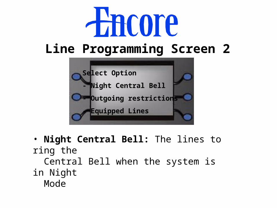
Select Option
- Night Central Bell
- Outgoing restrictions
- Equipped Lines
Line Programming Screen 2
• Night Central Bell: The lines to ring the Central Bell when the system is in Night Mode

• Outgoing Restrictions: Extensions can be restricted from accessing particular lines
• Equipped Lines: Program the lines that are actually equipped

Select Option
- Incoming Calls Only
- Outgoing Groups
- PBX Group
Line Programming Screen 3
• Incoming Calls Only: Lines which cannot be selected by any extension for outgoing calls
• Outgoing Groups: Lines can be grouped into four groups (9, 81, 82, 83) for outgoing calls
• PABX Group: Line Groups may be programmed to work off parent PBXs
– Program the line access digit(s) for the parent PBX
– Program the extension number length in the parent PBX

Select Option
- Hunt Groups
- Answering Machine
- Courtesy Service
Line Programming Screen 4
• Hunt Groups: Up to four groups can be programmed. A line cannot be in multiple groups.

• Answering Machine: Program those lines to be answered by the Voice Module when the Answering Machine Mode is turned on
• Courtesy Service: Program those lines to be answered by the Courtesy Service

Select Option
- Program CID No
- Alternative Routing
- Auto Attendant
Line Programming Screen 5
• Program Caller ID (CID) Number: A Table of 30
entries is programmed
– Each entry is programmed with a name
– Each entry can be associated with an extension to route the call based on the Caller ID

• Alternative Routing: Program as follows.
– Enter the Input Codes. When an extension dials one of these codes the alternative routing is to be invoked.
– Enter Output Code, if required. This code is dialed instead of the Input Code.
– Select the lines to be used for the Alternative Route.
– Select “Preferred” if a normal line may be used when none of the Alternative Lines are available.
– Select “Exclusive” if the Alternative Lines only may be used.

• Auto Attendant: Program the lines that will be answered by the Auto Attendant

Select Option
- PSTN Programming
- Cancel
Line Programming Screen 6
When PSTN Programming is selected a sub-menu is displayed

PSTN Programming Sub-Menu
Select Option
- Tone Dialing
- Timed Break
- Loop Calling
Screen 1
• Tone Dialing: Set Tone Dialing Or Pulse Dialing
• Timed Break: Set Timed Break or Ground Recall as the Forward Recall Signal

• Loop Calling: Program those lines which do not look to detect dial tone (for example, ring-down circuits)
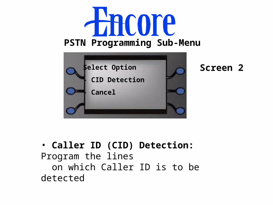
PSTN Programming Sub-Menu
Select Option
- CID Detection
- Cancel
Screen 2
• Caller ID (CID) Detection: Program the lines
on which Caller ID is to be detected

Section 5
System Hardware Descriptions

• Hitachi 16-bit Microprocessor
• Memory
– Twin Flash EPROMs (4 Megabytes each)
– RAM (2 Megabit)
• Analog and Digital Switch Matrix
• Six Extension Interfaces
CPU Main Components

• DTMF Sender
• DTMF Receiver
• Dial Tone Detector
• Crosspoint Matrix
• Connectors for Modules and Expansion Cards
• Switched Mode PSU 75 VAC
• Voltages available:
– 0 Volts
– 0 Volts “Protect”
– -40 Volts Analog
– -40 Volts Digital
– -35 Volts (for 5V rail)
– -31 Volts (for 9V rail)
– Ringing voltage
Power Supply

6-Port Keyset Card
• Six Extension Circuits
• DTMF Receiver
• Crosspoint Matrix
• Connector for 2-Port Loop Start Card

2-Port Loop Start Card
• Interface for two Loop Start Lines
Section 6
System Maintenance

System Maintenance• All hardware faults are fixed by board replacement
• Programming errors can be corrected locally or remotely
• Diagnostic tests and data are available from the Camino PC Maintenance and Programming
Package

Removing the CPU • Remove expansion boards• Remove cabling• Remove power supply connectors• Remove retaining screws• Remove the CPU
The CPU board is secured to the KSU base by screws and plastic retaining clips.

Replacing the CPU
• Insert the CPU and retaining screws• Reconnect the two power supply leads• Reconnect cabling• Reinstall expansion boards

Removing the Power Supply Unit
• Unplug the power cord
• Disconnect the Battery Backup Unit
• Remove the Power Supply Unit cover
• Disconnect the power lead
• Unplug the two leads going to the CPU
• Unscrew the two retaining screws
• Remove the unit

Installing a Power Supply Unit• Insert the unit
• Screw in the two retaining screws
• Connect the power lead
• Plug in the two leads to the CPU
• Replace the unit cover
• Reconnect the power cord
• Reconnect the Battery Backup Unit

Troubleshooting
• No incoming calls on a phone:
– Check that DND is not set
– Check that all Call Forwarding is not set (listen for interrupted dial tone)
• Keyset shows “Waiting for Sync”:
– Check phone cabling and connection
• No dial tone:
– Check that Extension Disconnection is not programmed

• Line cannot be selected:
– Ensure that it is programmed in “Equipped Lines”
– Check that it is not programmed for “Incoming only”
– If trying to select with a Line Key, check the key programming
• Single-line phone cannot make external calls:
– Plug in a Keyset and see if Extension Lock is
programmed

• Answering machine or fax is answering incoming calls:
– Ensure that they are not in the ringing group