Embed Size (px)
Citation preview
Running Head: FEAS. JOIN. TP & TC 1
Feasibility of Joining Techniques for Thermoplastic and Thermoset Polymers
Prepared by:
Kimberly C. De Boer
Faculty Advisors:
Dr. Michael West
REU Site Director, Department of Materials and Metallurgical Engineering
Dr. Cassandra Kingsbury
Assistant Professor, Mechanical Engineering
Dr. Alfred Boysen
Professor, Department of Humanities
Program Information:
National Science Foundation
Grant NSF #DMR-1157074
Research Experience for Undergraduates
Summer 2013
South Dakota School of Mines and Technology
501 E Saint Joseph Street
Rapid City, SD 57701
FEAS. JOIN. TP & TC 2
TABLE OF CONTENTS
Abstract ………………………………………………………………………………………….3
Introduction ………………………………………………………………………………….......4
Broader Impact …………………………………………………………………………………..6
Procedure ………………………………………………………………………………………..6
Materials ………………………………………………………………………………...6
Equipment and Procedures ……………………………………………………………...7
Results …………………………………………………………………………………………11
Discussion ……………………………………………………………………………………..14
Conclusion ……………………………………………………………………………………..14
References ……………………………………………………………………………………...16
Acknowledgments ……………………………………………………………………………...18
FEAS. JOIN. TP & TC 3
Abstract
In industry, ultrasonic welding is a well-known technique for thermoplastics; however,
less is known about the ultrasonic welding of thermosets. Similarly, friction stir spot welding is
known to be successful for high density polyethylene (HDPE), a thermoplastic but for few other
polymers. Joining techniques such as ultrasonic welding and friction stir welding have
advantages because of their reproducibility, ease of automation, and short welding time, over
other polymer joining techniques such as adhesives, solvent welding, or mechanical fastening.
This study aims to evaluate the joining techniques of FSSW and USSW for a thermoplastic,
polycarbonate, and a thermoset, EPON 828:DETA epoxy.
FEAS. JOIN. TP & TC 4
Introduction
Within the last 50 years, plastics technology has advanced incredibly (“The Polymer
Revolution”), to the point that manufactured plastic items are so large or complicated that they
cannot be fabricated with one mold. In many cases, parts must be fabricated from several smaller
pieces joined together, making the joining method a crucial step. Common methods available are
adhesives, mechanical fastening such as with nuts and bolts, spin welding, friction stir welding,
vibration welding, thermal welding, and ultrasonic welding (Rashli). The methods of mechanical
fastening and adhesives tend to be slow compared to welding. Indeed, ultrasonic welding and
friction stir welding are comparatively quick to complete and are easily automated, making these
methods attractive for manufacturing processes.
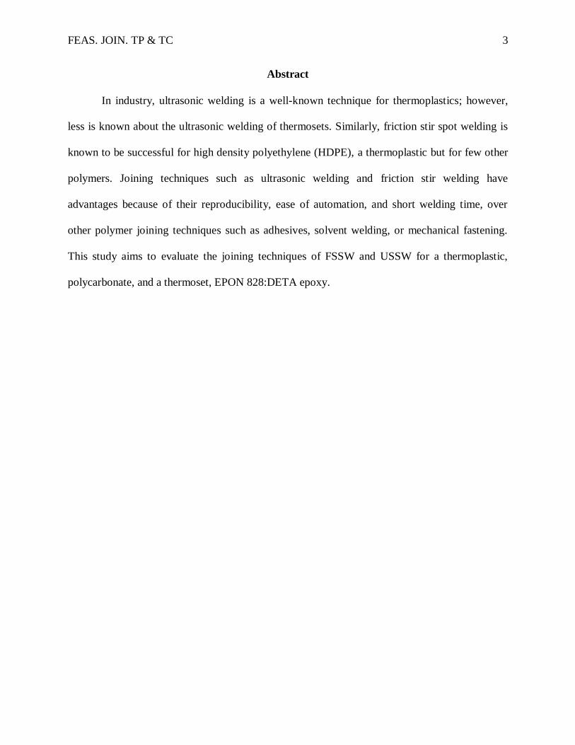
Ultrasonic spot welders (Fig. 1) take in electrical power oscillating at 50 to 60 Hz and
increase the frequency to or above 20,000 Hz. This high frequency electricity converts to
mechanical energy through a transducer, often piezoelectric. A booster amplifies the movement
and a sonotrode applies the vibrations to the work pieces to be welded. The vibrations oscillate
through the work pieces to heat the
interface. In addition to the vibration
applied by the sonotrode, a downward
force applies a weld pressure to the work
pieces. For this reason, components to be
ultrasonically welded must be able to
support pressure at the joint.
Figure 1: Schematic of Sonobond Ultrasonic Welder at SDSMT (Author's Work)
FEAS. JOIN. TP & TC 5
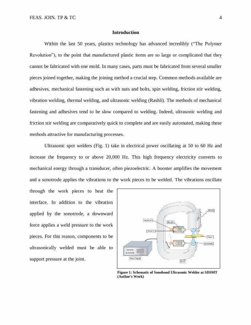
Unlike ultrasonic spot welding (USSW),
friction stir spot welding (FSSW) operates by spinning
an end mill on the parts to be welded (Fig. 2). The
collar descends into the workpiece, holding it in place.
Then, the spinning shoulder descends into the material
while the pin rises. As the shoulder ascends out of the
material, the pin descends so that it is flush with the
shoulder, creating a flat, filled FSSW joint.
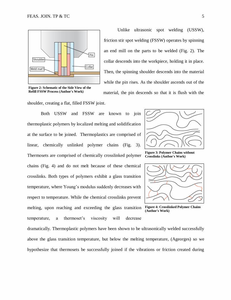
Both USSW and FSSW are known to join
thermoplastic polymers by localized melting and solidification
at the surface to be joined. Thermoplastics are comprised of
linear, chemically unlinked polymer chains (Fig. 3).
Thermosets are comprised of chemically crosslinked polymer
chains (Fig. 4) and do not melt because of these chemical
crosslinks. Both types of polymers exhibit a glass transition
temperature, where Young’s modulus suddenly decreases with
respect to temperature. While the chemical crosslinks prevent
melting, upon reaching and exceeding the glass transition
temperature, a thermoset’s viscosity will decrease
dramatically. Thermoplastic polymers have been shown to be ultrasonically welded successfully
above the glass transition temperature, but below the melting temperature, (Ageorges) so we
hypothesize that thermosets be successfully joined if the vibrations or friction created during
Figure 2: Schematic of the Side View of the Refill FSSW Process (Author's Work)
Figure 3: Polymer Chains without Crosslinks (Author's Work)
Figure 4: Crosslinked Polymer Chains (Author's Work)

FEAS. JOIN. TP & TC 6
a.
b.
c.
welding of the ultrasonic welder raise the temperature of the samples above the glass transition
temperature.
Broader Impact
Thermoplastic polymers are widely used in the packaging industry for their ease of
formation, low cost, and their ability to be reworked (Rashli). Thermoplastics work well in low-
temperature applications, and certain thermoplastics have a very high impact strength,
mechanical strength, and temperature resistance (GEHR plastics PC polycarbonate). They can
even be reinforced with fibers, in some applications.
Fiber reinforced polymers (FRPs) often use a thermoset matrix and knowledge from this
study on the joining of a common thermoset could be extended to apply to the field of FRP
structure manufacturing. Ultrasonic welding provides an alternative bonding method that can be
better and easier to automate than adhesives, mechanical bonding techniques, and other welding
techniques. Most of the joining methods listed above disturb the fibers at the joint, require long
curing times, or create stress concentrations. Ultrasonic welding is fast and does not disturb the
fibers or create stress concentrations. Welding FRPs could reduce the time, and thus the cost, of
joining FRP components. Since they are strong and lightweight, FRP components give a serious
advantage over metal, concrete, and other materials.
Procedure
Materials
The thermoset used was a two part epoxy of
EPON 828 and diethylene triamine (DETA) The DETA
was mixed at a ratio of 8 parts per hundred (pph) parts of
EPON 828. When cured at 24 hours room temperature
Figure 3: Chemical Structures of (a.) PC, (b.) EPON 828, and (c.) DETA (Public Domain)

FEAS. JOIN. TP & TC 7
(RT), 24 hours 35°C, 1hour 135°C, it had a glass transition temperature of 72°C. (Caruso)
For comparison, polycarbonate (PC) a well-known thermoplastic was also used. It has a
clear appearance and melts at 149°C (Plastic properties of polycarbonate).
Equipment and Procedures
Samples of epoxy and PC were produced (1”x4”x1/16”). In order to make appropriately
sized samples of epoxy an aluminum master mold (Fig. 6) was cut to shape with a CNC mill.
Miller Stephenson polytetrafluoroethylene (PTFE) spray acted as a release agent and silicone
(one made with Sylgard 184 cured
22 hours RT and 2 hours 70°C, one
made with Contenti Room
Temperature Vulcanizing Silicone
Rubber No. 179-050 cured 24
hours RT, Fig. 7) was poured into
the master mold to create the mold
in which the epoxy samples would
be formed. After the silicone molds
were cured, the epoxy was mixed at 8 pph, de-gassed at 650 mm Hg for 5 minutes and cured for
24 hours at room temperature, 24 hours in
a Lindberg Blue M Mechanical
Convection Oven at 35°C and 1 hour at
135°C in a Lab-Line Programmable
Vacuum Oven.
Figure 5: Master Mold (Author's Work)
Figure 4: Silicone Molds (Author's Work)
FEAS. JOIN. TP & TC 8
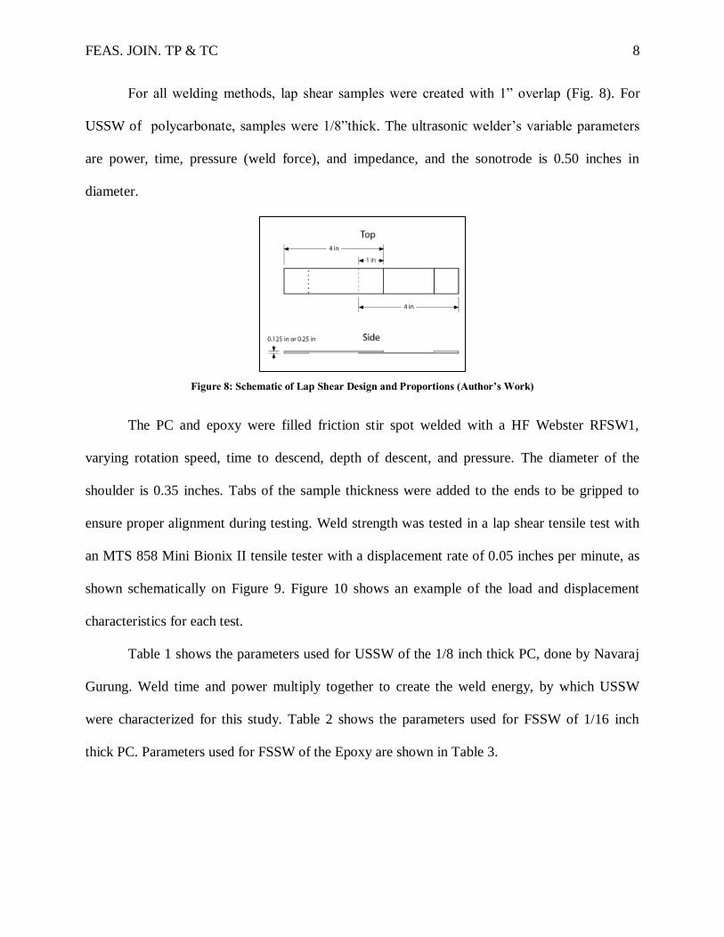
For all welding methods, lap shear samples were created with 1” overlap (Fig. 8). For
USSW of polycarbonate, samples were 1/8”thick. The ultrasonic welder’s variable parameters
are power, time, pressure (weld force), and impedance, and the sonotrode is 0.50 inches in
diameter.
Figure 8: Schematic of Lap Shear Design and Proportions (Author’s Work)
The PC and epoxy were filled friction stir spot welded with a HF Webster RFSW1,
varying rotation speed, time to descend, depth of descent, and pressure. The diameter of the
shoulder is 0.35 inches. Tabs of the sample thickness were added to the ends to be gripped to
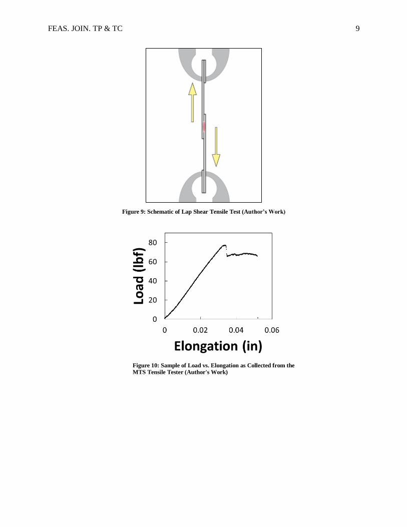
ensure proper alignment during testing. Weld strength was tested in a lap shear tensile test with
an MTS 858 Mini Bionix II tensile tester with a displacement rate of 0.05 inches per minute, as
shown schematically on Figure 9. Figure 10 shows an example of the load and displacement
characteristics for each test.
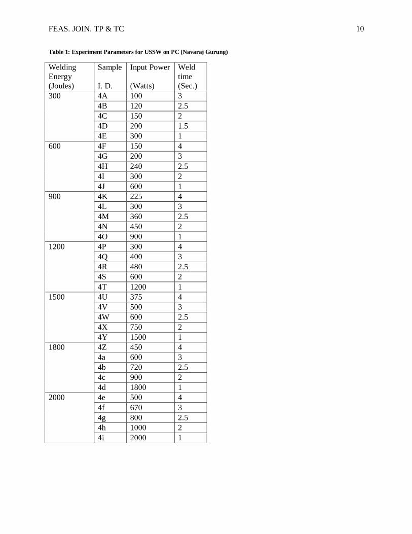
Table 1 shows the parameters used for USSW of the 1/8 inch thick PC, done by Navaraj
Gurung. Weld time and power multiply together to create the weld energy, by which USSW
were characterized for this study. Table 2 shows the parameters used for FSSW of 1/16 inch
thick PC. Parameters used for FSSW of the Epoxy are shown in Table 3.
FEAS. JOIN. TP & TC 9
Figure 9: Schematic of Lap Shear Tensile Test (Author’s Work)
Figure 10: Sample of Load vs. Elongation as Collected from the MTS Tensile Tester (Author's Work)
FEAS. JOIN. TP & TC 10
Table 1: Experiment Parameters for USSW on PC (Navaraj Gurung)
Welding
Energy
Sample Input Power Weld
time
(Joules) I. D. (Watts) (Sec.)
300 4A 100 3
4B 120 2.5
4C 150 2
4D 200 1.5
4E 300 1
600 4F 150 4
4G 200 3
4H 240 2.5
4I 300 2
4J 600 1
900 4K 225 4
4L 300 3
4M 360 2.5
4N 450 2
4O 900 1
1200 4P 300 4
4Q 400 3
4R 480 2.5
4S 600 2
4T 1200 1
1500 4U 375 4
4V 500 3
4W 600 2.5
4X 750 2
4Y 1500 1
1800 4Z 450 4
4a 600 3
4b 720 2.5
4c 900 2
4d 1800 1
2000 4e 500 4
4f 670 3
4g 800 2.5
4h 1000 2
4i 2000 1

FEAS. JOIN. TP & TC 11
Table 2: Experiment Parameters for FSSW on PC (Author’s Work)
Sample I.D.
Plunge Rate
Spindle Speed Pressure
(in/min) (RPM) (psi)
1 2 150 60
2 2 150 60
3 2 150 60
4 2 200 60
5 2 200 60
6 2 200 60
7 2 100 60
8 2 100 60
9 2 100 60
10 1.5 150 60
11 1.5 150 60
12 1.5 150 60
13 2.5 150 60
14 2.5 150 60
15 2.5 150 60
16 1.5 150 60
17 2.5 150 60
Table 3: Results of FSSW on Epoxy with Experimental Parameters (Author's Work)
Plunge rate
Plunge Depth
Time to Depth
Spindle Speed Pressure Comments
in/min (mm) (sec.) (RPM) (psi) 2.2 3.7 4 100 100 Shattered, but bonded some
2.2 3.7 4 50 100 Crushed the sample
1.9 3.25 4 100 100 shattered.
4.0 4.93 2.9 500 60 Crushed the sample, shattered
1.0 3.73 8.81 100 60 Shattered, but bonded some
Results
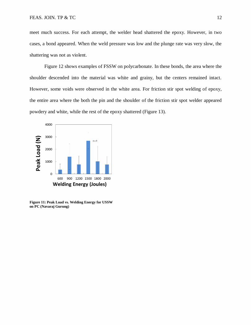
The lap shear strength of polycarbonate ultrasonic spot welds peaked when the weld
energy was 1500 joules as shown in Figure 11 (Navaraj Gurung). When friction stir spot welding
was attempted on polycarbonate, the strongest bonds were observed when the spindle speed was
high and when the plunge rate was low. Unfortunately, friction stir spot welds on epoxy did not
FEAS. JOIN. TP & TC 12
meet much success. For each attempt, the welder head shattered the epoxy. However, in two
cases, a bond appeared. When the weld pressure was low and the plunge rate was very slow, the
shattering was not as violent.
Figure 12 shows examples of FSSW on polycarbonate. In these bonds, the area where the
shoulder descended into the material was white and grainy, but the centers remained intact.
However, some voids were observed in the white area. For friction stir spot welding of epoxy,
the entire area where the both the pin and the shoulder of the friction stir spot welder appeared
powdery and white, while the rest of the epoxy shattered (Figure 13).
Figure 11: Peak Load vs. Welding Energy for USSW
on PC (Navaraj Gurung)

FEAS. JOIN. TP & TC 13
Figure 12: An Example of FSSW on 1”x 1” PC (Author’s Figure 13: FSSW on Epoxy. The short dimension of the
Work) original epoxy sample is 1” wide. (Author’s Work)
Lap shear testing of friction stir spot welded PC shows loose trends across welding
parameters. As the spindle speed increased, so did the peak load (Figure 14) and as the plunge
rate increased, the peak load decreased (Figure 15).
Figure 14: Peak Load vs. Spindle Speed for FSSW Figure 15: Peak Load vs. Plunge Rate for FSSW on PC
on PC (Author’s Work) (Author’s Work)
FEAS. JOIN. TP & TC 14
As Figure 11 shows, the peak load of the USSW joints on PC was at 1500N joules, and
beyond that point, bonds became weaker. Below, in Table 3, the qualitative results of FSSW on
epoxy are shown. All samples were shattered or crushed, but some formed some sort of bond in
the white center as shown in Figure 13.
Discussion
Polycarbonate was successfully joined with both FSSW and USSW, but the epoxy was
not successfully joined with FSSW, and due to instrument issues, was not able to be joined with
USSW. During welding, the polycarbonate demonstrated ductile behavior, while the epoxy
demonstrated brittle failure. Since the polycarbonate had stronger friction stir spot welds when
the spindle speed was higher and the plunge rate was lower, we hypothesize a stronger PC bond
could be achieved with more heat. Perhaps, as the ultrasonic spot welding of PC displayed, there
may be a parameter set for which peak strength may be attained.
Every epoxy sample that was friction stir spot welded shattered. However, when the
plunge rate was extremely low and the pressure was also low, the epoxy bonded some at the
location of the welder head, even though the rest of it shattered (Fig. 13). A possible reason that
a small bond was created was because the slow plunge rate allowed the friction of the welder to
heat the material more than the other samples.
Conclusion
The feasibility of USSW and FSSW of polycarbonate and epoxy is studied. The amount
of heat generated during both joining techniques plays a crucial role in welding and should
correspond to the glass transition and melting temperatures of the materials for a successful bond
Because a low plunge rate allows for more heating of the epoxy, it is possible that even
lower plunge rates or preheated samples could be explored for friction stir spot welding of epoxy

FEAS. JOIN. TP & TC 15
in future studies. Additional studies should also experiment with faster spindle speeds and lower
plunge rates for FSSW on polycarbonate. Since ultrasonic spot welding could not be attempted
on epoxy this summer, that is another area of future work, as it is likely that method will not
shatter the brittle epoxy.
FEAS. JOIN. TP & TC 16
References
Ageorges, C., Ye, L., & Hou, M. (2001). Advances in fusion bonding techniques for joining
theromoplastic matrix composites: a review [Electronic version]. Composites: Part A,
839-857.
Balle, F., Wagner, G., & Eifler, D. (2009). Joining of Aluminum 5754 Alloy to carbon fiber
reincforced polymers (CFRP) by ultrasonic welding. Aluminum Alloys; fabricaiton,
characterization and applications II; proceedings of symposia sponsored by the Light
Metals Division of the Minerals, 191-196.
Benatar, A. (1987). Ultrasonic welding of advanced thermoplastic composites Doctoral
dissertation, Massachusetts Institute of Technology.
Caruso, M. M. (2010). Solvent-based self-healing polymeric materials. (Order No. 3452150,
University of Illinois at Urbana-Champaign). ProQuest Dissertations and Theses, , 286.
Retrieved from http://search.proquest.com/docview/863676875?accountid=44996.
(prod.academic_MSTAR_863676875).
GEHR plastics PC polycarbonate . (n.d.). In MatWeb. Retrieved August 9, 2013
Groover, M. P. (2003). Fundamentals of modern manufacturing: Materials, processes, and
systems (2nd ed., pp. 953-961). Hoboken, NJ: Wiley.
Harras, B., Cole, K. C., & Vu-Khanh, T. (1996). Optimization of the ultrasonic welding of
PEEK-carbon composites. Journal of reinforced plastics, 15(2), 174-181.
Lin, P. H., & Khare, R. (2010, August). Local chain dynamics and dynamic heterogeneity in
cross-linked epoxy in the viscinity of glass transition. Macromolecules, 43(15), 6505-
6510.
Liu, S., Chang, I., & Hung, S. (2001, February). Factors affecting the joint strength of
ultrasonically welded polypropylene components [Electronic version]. Polymer
Composites, 22(1), 132-141.
Madhup, M., & Yadav, J. (2013). Investigation of Glass transition temperature (Tg) of Bisphenol
A based epoxy resin and cyclo-aliphatic amine system with variation of stoichiometry.
Paintindia, 63(1), 53-55.
Plastic properties of polycarbonate (PC) . (n.d.). In Dynalab Corp. Retrieved July 29, 2013.
Rani, M. R., Prakasan, K., & Rudramoorthy, R. (2009, July/August). Study of different joints for
ultrasonic welding of semicrystalline polymers [Electronic version]. Experimental
Techniques, 33(4), 36-42.
FEAS. JOIN. TP & TC 17
Rani, M. R., Suresh, K. S., Prakasan, K., & Rudramoorthy, R. (2007, September/October). A
statistical study of parameters in ultrasonic welding of plastics [Electronic version].
Experimental Techniques, 31(5), 53-58.
Rashli, R., Bakar, E. A., Kamaruddin, S., & Othman, A. R. (2013, February 7). A review of
ultrasonic welding of thermoplastic composites. Caspian Journal of Applied Sciences
Research, 2(3), 01-16. Retrieved from CJASR.
The polymer revolution. (2008). New Internationalist, (415), 8-9.
Troughton, M. J. (2008). Handbook of plastics joining: A practical guide (2nd ed., pp. 15-35).
Norwich, NY: William Andrew Inc.
FEAS. JOIN. TP & TC 18
Acknowledgments
Funding for this research was provided by the National Science Foundation. Thanks to
research advisor, Dr. Cassandra Kingsbury and REU site director Dr. Michael West for their
direction and guidance, and to Dr. Alfred Boysen, Professor of English, for his critique in writing
and speaking and moral support. A special thank-you goes to Mr. Aaron Lalley for instructing
me on how to use the CNC mill, and also to all the other faculty and staff that helped me at
SDSMT.