Embed Size (px)
Citation preview

MICMAT 1893 ARTICLE IN PRESS No. of Pages 9, DTD=5.0.1
31 October 2004 Disk used
ELSEVIER
Available online at www.sciencedirect.com
S C I E N C E f / T ) D I R E C T ® I N C E D I
Microporous and Mesoporous Materials xxx (2004) xxx-xxx
MICROPOROUSAND MESOPOROUS MATERIALS
www.elsevier.com/Iocate/micromeso
Preparation of silicalite-1 layers on Pt-coated carbon materials: a possible electrochemical approach towards membrane reactors
4 A. Berenguer-Murcia a, E. Morallón b, D. Cazorla-Amorós a'*, Á. Linares-Solano a Departamento de Química Inorgánica, Universidad de Alicante, Ap. 99, San Vicente del Raspeig, E-03080 Alicante, Spain
b Departamento de Química Física, Universidad de Alicante, Ap. 99, San Vicente del Raspeig, E-03080 Alicante, Spain
Received 17 June 2004; received in revised form 4 October 2004; accepted 5 October 2004
9 Abstract
10 A novel kind of composites is synthesized due to the outstanding properties of carbon materials. Metallic platinum is deposited 11 on porous carbon discs by means of Potential Step Deposition (PSD) under potentiostatic conditions. Afterwards, the Pt-coated 12 discs were covered completely with colloidal zeolite (silicalite-1) crystals by means of the novel Electro Phoretic Deposition 13 (EPD) methodology. After standard hydrothermal treatment, the seed crystal coating becomes continuous, crack-free and well-14 intergrown, giving rise to a layer of silicalite-1 crystals of different sizes. It must be noted that Pt combined with the secondary 15 growth methodology has a extremely important effect on the orientation of the growing zeolite crystals. These novel materials have 16 a wide range of potential applications as membrane reactors and/or catalyst membranes after activation (i.e. template removal by 17 calcination) of the zeolite crystals. 18 © 2004 Published by Elsevier Inc.
19 Keywords: Silicalite-1; Electro phoretic deposition; Membrane reactors; Carbon materials 20
2 1 1 . I n t r o d u c t i o n
22 As a direct consequence of the many applications of 23 crystalline zeolites, such as ion exchangers, adsorbents, 24 and molecular sieves fl], and all the possibilities implied 25 therein, increasing attention has been paid to preparing 26 zeolite membranes over the years [2], 27 Considering the many different strategies that have 28 been employed nowadays [3-7] and the wide variety of 29 supports that have been tested already [3-24], one might 30 think that the issue of preparing a supported zeolite 31 membrane has been successfully achieved. This, how-32 ever is not so, because even from the initial approach 33 of the direct treatment of the support with a zeolite pre-34 cursor solution [8], it was clear that a significant layer
" Corresponding author. Tel.: +34 96 590 39 46; fax: +34 96 590 34 54.
E-mail address: [email protected] (D. Cazorla-Amorós).
thickness was needed to obtain a continuous film [25], 35 More recently, the seed film method has been introduced 36 with the aim to better control the growth of zeolites on 37 the studied supports [26-33], This methodology can be 38 adapted to substrates with rather different chemical nat- 39 ure, making the synthesis of thin oriented layers of zeo- 40 lite crystals possible (see for example Refs. [26,31]). The 41 main aim of the seed film method, attempted by some 42 different approaches, is to systematically cover the sur- 43 face of the support with a layer of zeolite crystals so 44 that, according to the classical theory of crystal forma- 45 tion, the nucleation step is thus skipped. The advantages 46 brought for by this method are that shorter synthesis 47 times are needed for a continuous zeolite layer to grow 48 on the support and that preferential orientation is more 49 easily achieved. 50
On the other hand, quite recent studies [34,35] have 51 tackled the issue of membrane reactors, studying the 52 applicability of such aforementioned zeolite membranes 53
1387-181 l/S - see front matter © 2004 Published by Elsevier Inc. doi: 10.1016/j micromeso.2004.10.005
MICMAT 1893
31 October 2004 Disk used ARTICLE IN PRESS No. of Pages 9, DTD =5.0.1
Á. Berenguer-Murcia et al. / Microporous and Mesoporous Materials xxx (2004) xxx-xxx
54 to continuous membrane reactors (CMRs) [34] or as 55 selectivity enhancers for reactive gas sensors [35], In 56 the latter case, the addition of a zeolite membrane im-57 proves the selectivity of semiconductor-based sensors. 58 Although finally applied to a system that could be 59 named a membrane reactor, the zeolite membrane itself 60 is only used as a molecular sieve layer, in what is known 61 as an inert membrane reactor. Up to now, some works 62 [36,37] have reported the use of a zeolite membrane cou-63 pled with a catalytically active species in intimate con-64 tact but outside the membrane, thus constituting a so-65 called combined membrane reactor. This work adds 66 up to these aforementioned works, in which a separation 67 layer is deposited on a metallic catalytically active layer. 68 Other examples of membrane reactors can be found in 69 the literature (see for example, Refs. [38,39]), but in such 70 cases, the separation layer (zeolite) acts as the catalyst 71 itself (catalytic membrane reactor), and thus are differ-72 ent from those presented in this communication, a com-73 bined membrane reactor, in which the catalytic material 74 can be inside or outside the separation layer, but not 75 being a part of it. 76 Recent reports have shown the interesting applica-77 tions of Electro Phoretic Deposition (EPD) [40,41] as a 78 simple suitable method to deposit homogeneous films 79 of colloidal zeolite seeds on materials with different 80 shapes, although to the best of our knowledge, there have 81 been few results on the preparation of zeolite membranes 82 using EPD [41], Our research group has very recently re-83 ported the successful synthesis of continuous, defect-free 84 layers of silicalite-1 on carbon materials by secondary 85 growth using EPD as the seeding technique [42], 86 In conclusion, the purpose of the present work is to 87 integrate both the molecular sieving layer and the cata-88 lytic layer onto the same system, thus making a combined 89 membrane reactor. The scope for doing this is mainly fo-90 cused on the electric properties of carbon (that is, being 91 carbon electricity conducting). From this point of view, 92 our two main objectives would be to first deposit a cata-93 lytically active species (metallic platinum) on the surface 94 of a carbon support by means of the Potential Step Dep-95 osition (PSD) method under potentiostatic conditions 96 and then perform the EPD of a coating of zeolite colloi-97 dal seeds in order to grow continuous zeolite films on top 98 of the catalytically active species by standard hydrother-99 mal treatment. The remarkable influence of the deposi-
100 tion of platinum on the final composite is discussed.
101 2. Experimental
102 2.1. Preparation of the supports and platinum deposition
103 Macroporous carbon discs were cut from a macro-104 porous carbon sheet (thickness = 0.5 mm, mean pore 105 size 0.7 |im) provided by Poco Graphite (DFP-1). For
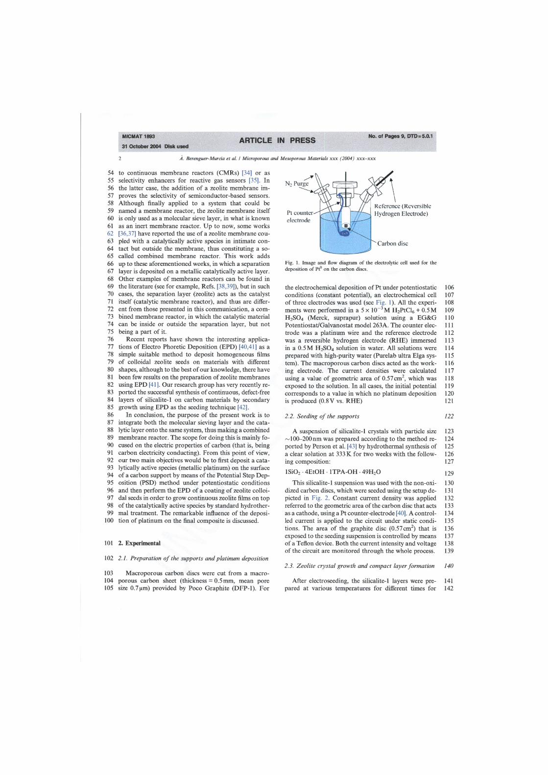
Fig. 1. Image and flow diagram of the electrolytic cell used for the deposition of Pt° on the carbon discs.
the electrochemical deposition of Pt under potentiostatic conditions (constant potential), an electrochemical cell of three electrodes was used (see Fig. 1). All the experi-ments were performed in a 5 x 10™3 M H2PtCl6 + 0.5 M H 2 S0 4 (Merck, suprapur) solution using a EG&G Potentiostat/Galvanostat model 263A. The counter elec-trode was a platinum wire and the reference electrode was a reversible hydrogen electrode (RHE) immersed in a 0.5 M H 2 S0 4 solution in water. All solutions were prepared with high-purity water (Purelab ultra Elga sys-tem). The macroporous carbon discs acted as the work-ing electrode. The current densities were calculated using a value of geometric area of 0.57 cm2, which was exposed to the solution. In all cases, the initial potential corresponds to a value in which no platinum deposition is produced (0.8 V vs. RHE)
2.2. Seeding of the supports
A suspension of silicalite-1 crystals with particle size 00-200 nm was prepared according to the method re-
ported by Person et al. [43] by hydrothermal synthesis of a clear solution at 333 K for two weeks with the follow-ing composition:
lSi02 4EtOH • 1TPA-OH 49H20
This silicalite-1 suspension was used with the non-oxi-dized carbon discs, which were seeded using the setup de-picted in Fig. 2. Constant current density was applied referred to the geometric area of the carbon disc that acts as a cathode, using a Pt counter-electrode [40], A control-led current is applied to the circuit under static condi-tions. The area of the graphite disc (0.57 cm2) that is exposed to the seeding suspension is controlled by means of a Teflon device. Both the current intensity and voltage of the circuit are monitored through the whole process.
06 07 08 09 10 11 12 13 14 15 16 17 18 19 20 21
22
23 24 25 26 27
29 30 31 32 33 34 35 36 37 38 39
2.3. Zeolite crystal growth and compact layer formation 140
After electroseeding, the silicalite-1 layers were pre- 141 pared at various temperatures for different times for 142
" Carbon disc
\ Reference (Reversible Hydrogen Electrode) Pt
electrode
MICMAT 1893
31 October 2004 Disk used ARTICLE IN PRESS No. of Pages 9, DTD = 5.0.1
A Berenguer- Murcia et ai / Microporous and Mesoporous Materials xxx (2004) xxx-xxx
k
Seed suspension
Carbon support
Pt counter electrode
Fig. 2. Image and flow diagram of the setup used for the EPD of seed crystals on the carbon support.
143 comparison purposes. Silicalite-1 layers were grown on 144 the carbon supports by standard hydrothermal synthesis 145 as described in Refs. [7,21,33,42], The silicate solutions 146 were obtained from TEOS (tetraethyl orthosilicate) 147 (ALDRICH 13,190-3), adding high-purity NaOH (when 148 necessary) (ALDRICH 30,657-6). Tetrapropylammo-149 nium hydroxide (TPA-OH) (ALDRICH 25,453-3) and 150 tetrapropylammonium bromide (TPA-Br) (ALDRICH 151 2556-8), were used as the templating agents. A typical 152 composition of the synthesis solutions was:
154 lSi02 0.30TPA-OH 0.15NaOH 14.98H20 (1)
155 All synthesis were performed by triplicate to check the
156 reproducibility of the experiments.
157 2.4. Characterisation of the materials
158 The crystalline phases synthesized were characterized 159 by X-ray powder diffraction using a SEIFERT 2002 160 equipment. CuKoc (1.54A) radiation was used. The 161 scanning velocity was 2°/min, and the 20 range scanned 162 was from 2° to 60°. 163 The morphology of the synthesized composites was 164 studied by Scanning Electron Microscopy (SEM) using 165 a Hitachi S-3000N equipment. The chemical composi-166 tion of the samples was analyzed by EDX (coupled to 167 the SEM equipment. Link QX-200).
168 3. Results and discussion
169 3.1. Platinum deposition by PSD
170 As a first approach towards the deposition of metallic 171 platinum on the carbon supports, we conducted two sets 172 of experiments: (i) keeping a fixed voltage pulse (fixed 173 initial and end pulse voltage) and applying the corre-174 sponding pulse for different times. Fig. 3A and B show
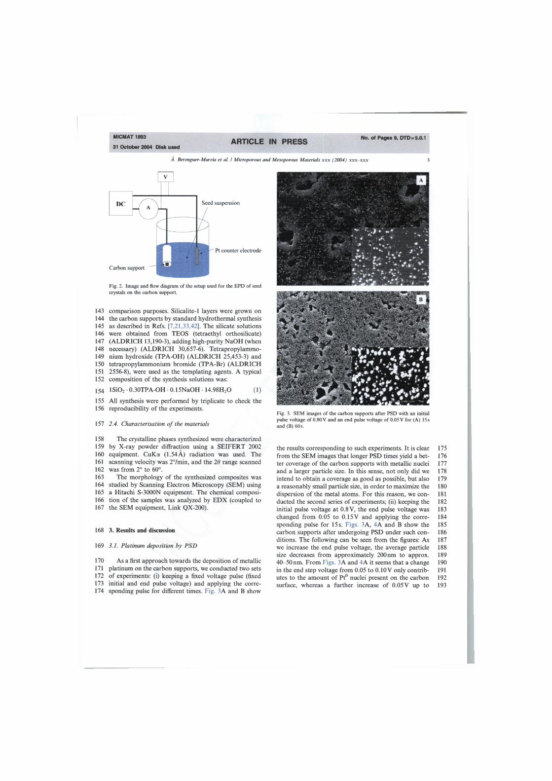
Fig. 3. SEM images of the carbon supports after PSD with an initial pulse voltage of 0.80V and an end pulse voltage of 0.05V for (A) 15s and (B) 60s.
the results corresponding to such experiments. It is clear 175 from the SEM images that longer PSD times yield a bet- 176 ter coverage of the carbon supports with metallic nuclei 177 and a larger particle size. In this sense, not only did we 178 intend to obtain a coverage as good as possible, but also 179 a reasonably small particle size, in order to maximize the 180 dispersion of the metal atoms. For this reason, we con- 181 ducted the second series of experiments; (ii) keeping the 182 initial pulse voltage at 0.8V, the end pulse voltage was 183 changed from 0.05 to 0.15 V and applying the corre- 184 sponding pulse for 15 s. Figs. 3A, 4A and B show the 185 carbon supports after undergoing PSD under such con- 186 ditions. The following can be seen from the figures: As 187 we increase the end pulse voltage, the average particle 188 size decreases from approximately 200 nm to approx. 189 40-50nm. From Figs. 3A and 4A it seems that a change 190 in the end step voltage from 0.05 to 0.10 V only contrib- 191 utes to the amount of Pt° nuclei present on the carbon 192 surface, whereas a further increase of 0.05 V up to 193

MICMAT 1893
31 October 2004 Disk used ARTICLE IN PRESS No. of Pages 9, DTD = 5.0.1
4 A. Berenguer-Murcia et al. / Microporous
194 0.15 V (Fig. 4B) provokes the support to be covered with 195 substantially smaller metallic particles. 196 Another extremely important issue to address at this 197 point is to analyze the evolution of the delivered charge 198 with time, which can not only give us an idea of the 199 amount of platinum deposited on the carbon surface 200 through very simple calculations, but also the mecha-201 nism through which the deposition of metallic particles 202 is taking place [44]. When the electrochemical nucleation 203 and growth of different species takes place, according to 204 the model described by Scharifker and Hills [45], there 205 can be two possible nucleation mechanisms according 206 to their theoretical relationship, instantaneous nuclea-207 tion or progressive nucleation. In the former mecha-208 nism, all the nuclei are rapidly created and their 209 numbers remain constant during the growth process. 210 The other possible mechanism is the progressive nuclea-211 tion where the actual nucleation rate is low and new nu-212 clei are continuously forming during the whole 213 deposition process. The work of Bade et al. [46] is a very
Fig. 4. SEM images of the carbon supports after PSD for 15 s with an initial pulse voltage of 0.80 V and a end pulse voltage of (A) 0.10V and (B) 0.15V
Mesoporous Materials xxx (2004) xxx-xxx
good example of how to apply the corresponding equa- 214 tions to the progressive and instantaneous nucleation 215 mechanisms. 216
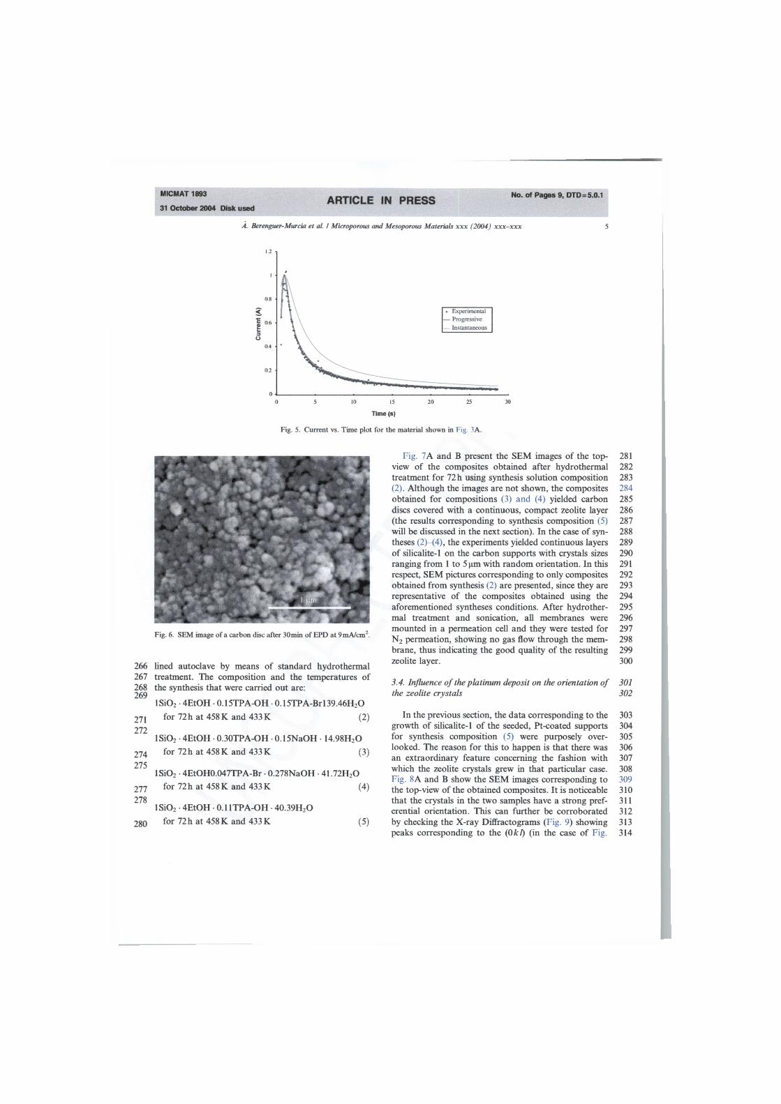
Thus, Fig. 5 shows the current vs. time graphs for 217 Fig. 3A. Nevertheless, it must be noted that the results 218 apply to all other figures corresponding to deposited 219 Pt° on the carbon supports. It is obvious that the data 220 fit those corresponding to the progressive nucleation 221 model almost perfectly, which is in agreement with our 222 experimental observations (the fairly broad metallic par- 223 tide size distribution observed by SEM suggested that 224 new nuclei were being formed continuously throughout 225 the PSD process). 226
3.2. Seeding of the Pt-coated supports 227
As already mentioned in the introduction section, our 228 research group has already reported the preparation of 229 continuous layers of silicalite-1 on carbon discs by 230 electrochemical methods [42]. In the aforementioned 231 communication we analyzed the influence of time and 232 applied current density of EPD in the seed crystal depos- 233 it on the surface of our carbon support, reaching the 234 conclusion that after an EPD process at 9mA/cm2 dur- 235 ing 30min, the seed crystal layer deposited on the car- 236 bon support is deemed appropriate for crystal growth. 237 Thus, all the forthcoming seeded materials mentioned 238 in this paper underwent the same EPD conditions (cur- 239 rent density: 9mA/cm2 EPD time: 30min). Fig. 6 shows 240 a top-view of one of such seeded materials. It is obvious 241 from the image that a complete coverage has been 242 achieved, and from our previous results we have con- 243 eluded that it is suitable for the growth of continuous 244 zeolite films by standard hydrothermal treatment. It 245 must be noted that the deposition of metallic platinum 246 does not hinder the use of the resulting carbon discs as 247 electrodes for electrophoresis. In fact, the results ob- 248 tained for both the Pt-coated and non-coated carbon 249 supports proved to be equally satisfactory. 250
3.3. Zeolite growth on the seeded, Pt-coated supports 251
Although the seed crystals layer might seem continu- 252 ous from the top-view SEM image, the space between 253 two crystals (i.e. intercrystalline gaps) is very significant, 254 so that in the whole surface of the carbon disc, there is a 255 considerable space that is not covered by zeolite crystals 256 and that is thus not affected by the molecular sieving 257 properties of zeolites. This, as a matter of fact, is the 258 main focus of our interest since we intend to use the 259 resulting materials as membranes in the near future. 260 As a result, the sealing off of the intercrystalline space 261 is mandatory towards possible membrane applications. 262 As mentioned in the Experimental section, the zeolite 263 growth took place by immersion of the seeded, Pt- 264 coated supports in the synthesis solution in a Teflon- 265
MICMAT 1893
31 October 2004 Disk used ARTICLE IN PRESS No. of Pages 9, DTD =5.0.1
Á. Berenguer-Murcia et al. / Microporous and Mesoporous Materials xxx (2004) xxx-xxx
in is Time (s)
20
Fig. 5. Current vs. Time plot for the material shown in Fig. 3A.
I M H i T
Fig. 6. SEM image of a carbon disc after 30min of EPD at 9mA/cm2.
266 lined autoclave by means of standard hydrothermal 267 treatment. The composition and the temperatures of 268 the synthesis that were carried out are: 269
lSi02 • 4EtOH • 0.15TPA-CJH • 0.15TPA-Brl39.46H20
2 7 1 for 72 h at 458 K and 433 K (2) 272
lSi02 4EtOH O.3OTPA-OH 0.15NaOH 14.98H20 274 for 72h at 458 K and 433 K (3) 275
lSi02 • 4EtOH0.047TPA-Br • 0.278NaOH • 41.72H20 277 for 72 h at 458 K and 433 K (4) 278
lSi02 4EtOH 0.11TPA-OH 40.39H20 280 for 72 h at 458 K and 433 K (5)
Fig. 7A and B present the SEM images of the top- 281 view of the composites obtained after hydrothermal 282 treatment for 72 h using synthesis solution composition 283 (2). Although the images are not shown, the composites 284 obtained for compositions (3) and (4) yielded carbon 285 discs covered with a continuous, compact zeolite layer 286 (the results corresponding to synthesis composition (5) 287 will be discussed in the next section). In the case of syn- 288 theses (2)—(4), the experiments yielded continuous layers 289 of silicalite-1 on the carbon supports with crystals sizes 290 ranging from 1 to 5 |atti with random orientation. In this 291 respect, SEM pictures corresponding to only composites 292 obtained from synthesis (2) are presented, since they are 293 representative of the composites obtained using the 294 aforementioned syntheses conditions. After hydrother- 295 mal treatment and sonication, all membranes were 296 mounted in a permeation cell and they were tested for 297 N2 permeation, showing no gas flow through the mem- 298 brane, thus indicating the good quality of the resulting 299 zeolite layer. 300
3.4. Influence of the platinum deposit on the orientation of 301 the zeolite crystals 302
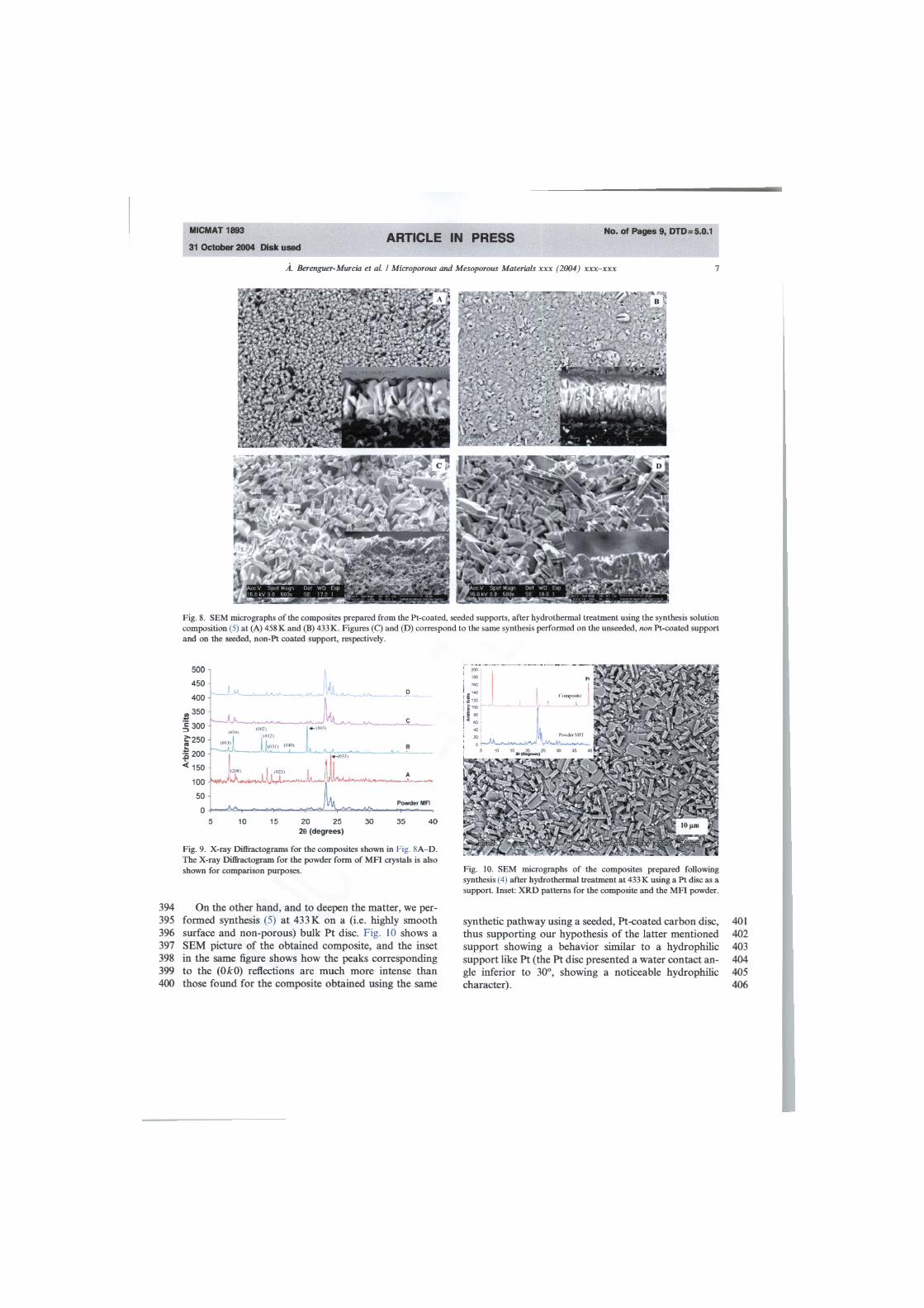
In the previous section, the data corresponding to the 303 growth of silicalite-1 of the seeded, Pt-coated supports 304 for synthesis composition (5) were purposely over- 305 looked. The reason for this to happen is that there was 306 an extraordinary feature concerning the fashion with 307 which the zeolite crystals grew in that particular case. 308 Fig. 8A and B show the SEM images corresponding to 309 the top-view of the obtained composites. It is noticeable 310 that the crystals in the two samples have a strong pref- 311 erential orientation. This can further be corroborated 312 by checking the X-ray Diffractograms (Fig. 9) showing 313 peaks corresponding to the (0 k I) (in the case of Fig. 314
Experimental Progressive Instantáneo us

315 316 317 318 319 320 321 322 323 324 325 326 327 328 329 330 331 332 333 334 335 336 337 338
m i c m a t 1893 ARTICLE IN PRESS No. of Pages 9 , o t d = , o ,
31 October 2004 Disk used
6 A. Berenguer-Murcia et al. I Microporous and
Fig. 7. SEM micrographs of the composites prepared from the Pt-coated, seeded supports, after hydrothermal treatment using the synthesis conditions specified in section 3.3. Note: The images correspond to synthesis composition (2) at (A) 458 K and (B) 433 K.
8A), and (0A:0) and (103) (in the case of Fig. 8B) reflec-tions that are noticeably more intense than those found in the polycrystalline X-ray Diffractogram for silicalite-1 [47], thus further corroborating the preferential orienta-tion (see Fig. 9).
After ascertaining the reproducibility of the remarka-ble results obtained (the synthesis was repeated on three different seeded, Pt-coated supports, obtaining identical results to those discussed above) and in order to further investigate the subject, the same synthesis procedure (synthesis solution composition, hydrothermal treat-ment time and temperature) was repeated using a car-bon disc (without any seeding or Pt deposition), a seeded carbon disc, and a Pt-coated disc without any seeding. In all three cases (the results corresponding to the experiments related to the seeded disc can be found in a previous communication by Berenguer-Murcia et al. [42]), no preferential orientation occurs. The results from all these experiments seem to suggest that only when a seeded, Pt-coated carbon disc is used as a sup-port, the final zeolite layer has a noticeable preferential orientation. Fig. 8C and D show the SEM images of sil-icalite-1 grown on the unseeded and seeded carbon disc (both non-Pt coated) and, as it can be seen, there is no
(esoporous Materials xxx (2004) xxx-xxx
preferential orientation whatsoever for the grown crys- 339 tals (this can be better acknowledged from the insets 340 in each figure and from Fig. 9 where the corresponding 341 diffractograms can be found). It is thus remarkable that 342 the deposition of Pt has such an effect concerning the 343 growth of crystals on its surface. As Ref. [19] summa- 344 rizes: "The final attachment to the support is obviously 345 strongly dependent on the type of support. Crystals can 346 chemically bind to the surface if surface OH groups are 347 present". Thus, considering that the Pt particles have a 348 high density of surface OH groups, the interaction be- 349 tween the metallic particles and the zeolite crystals must 350 be significant. Additionally, the potential applied 351 changes the surface charge of the Pt particles which 352 can favour the interaction of the seed crystals. 353
The difference in orientation for the samples prepared 354 at 458 and 433 K can be explained on the basis of crystal 355 growth kinetics provided that the support is sufficiently 356 hydrophilic. At 458 K, the crystals grow at a much faster 357 rate, and thus the fastest-growing crystal direction (the c 358 direction) is oriented towards the Si02-rich part of the 359 reaction system (which would be the synthesis solution). 360 At 433 K, though, this crystal growth rate is noticeably 361 inferior and thus, considering the alkali-free environ- 362 ment, the crystal growth mechanism is most probably 363 that described by Jansen et al. [19], It might seem highly 364 unlikely that with an uneven and hydrophobic as surface 365 as that of our carbon support it would be possible to 366 achieve such crystal orientation. In spite of the extreme 367 surface roughness of our support, the metallic platinum 368 particles may act as extremely efficient anchoring loca- 369 tions, playing a remarkable role in terms of both crystal 370 growth and orientation. In fact, given the fairly homoge- 371 neous coating of Pt particles on the surface of the sup- 372 port, we may be introducing a "metal-like" surface 373 that is extremely convenient. The introduction of these 374 particles with a high density of surface OH groups en- 375 hances the crystallization kinetics. Furthermore, it is a 376 well-known fact that the secondary growth method im- 377 proves the kinetics of zeolite layer formation. 378
The combination of these two effects (Pt particles and 379 seeding) provokes our support to behave as a "classical" 380 hydrophilic support, thus the remarkable results. It may 381 then seem that the presence of the small Pt particles fa- 382 vours a strong attachment of the silicalite-1 colloidal 383 seeds which will not redistribute significantly during 384 the hydrothermal treatment, making it thus possible to 385 grow oriented zeolite films. However, and as it can be 386 seen from Fig. 8B, the roughness of the carbon discs pre- 387 vails sometimes causing poor crystal orientation in some 388 regions. Then again, it must be highlighted that the dep- 389 osition of Pt on the surface is a critical factor for the 390 crystals to grow with their b direction perpendicular to 391 the support surface, which is something we have never 392 come across using carbon discs as supports. 393
MICMAT 1893
31 October 2004 Disk used ARTICLE IN PRESS No. of Pages 9, DTD =5.0.1
Á. Berenguer-Murcia et al. / Microporous and Mesoporous Materials xxx (2004) xxx-xxx
Fig. 8. SEM micrographs of the composites prepared from the Pt-coated, seeded supports, after hydrothermal treatment using the synthesis solution composition (5) at (A) 458 K and (B) 433 K. Figures (C) and (D) correspond to the same synthesis performed on the unseeded, non Pt-coated support and on the seeded, non-Pt coated support, respectively.
20 25 28 (degrees)
Fig. 9. X-ray Diffractograms for the composites shown in Fig. 8A -D. The X-ray Diffractogram for the powder form of MFI crystals is also shown for comparison purposes.
394 On the other hand, and to deepen the matter, we per-395 formed synthesis (5) at 433 K on a (i.e. highly smooth 396 surface and non-porous) bulk Pt disc. Fig. 10 shows a 397 SEM picture of the obtained composite, and the inset 398 in the same figure shows how the peaks corresponding 399 to the (0A:0) reflections are much more intense than 400 those found for the composite obtained using the same
Fig. 10. SEM micrographs of the composites prepared following synthesis (4) after hydrothermal treatment at 433 K using a Pt disc as a support. Inset: XRD patterns for the composite and the MFI powder.
synthetic pathway using a seeded, Pt-coated carbon disc, 401 thus supporting our hypothesis of the latter mentioned 402 support showing a behavior similar to a hydrophilic 403 support like Pt (the Pt disc presented a water contact an- 404 gle inferior to 30°, showing a noticeable hydrophilic 405 character). 406
IwJw Mil

MICMAT 1893
31 October 2004 Disk used ARTICLE IN PRESS No. of Pages 9, DTD =5.0.1
Á. Berenguer-Murcia et al. / Microporous and Mesoporous Materials xxx (2004) xxx-xxx
407 4. Conclusions
408 In summary, composites comprising a molecular 409 sieve layer, a catalytically active section and a macro-410 porous support have been synthesized by a simple and 411 straightforward method thanks to the remarkable elec-412 trical properties of the carbon support used. Its conduc-413 tivity has enabled the deposition of both metallic 414 particles by PSD (which may act as a supported catalyst) 415 and colloidal zeolite crystals by EPD, which are used in 416 the following step as seeding nuclei. The coating of zeo-417 lite seeds is transformed into a continuous layer of well-418 intergrown silicalite-1 crystals by standard hydrother-419 mal treatment. It is very important to highlight the sig-420 nificant changes that the addition of metallic Pt in the 421 system brings forth: the presence of small metallic parti-422 cles during secondary zeolite growth makes the growing 423 zeolite crystals to have a certain orientation that can be 424 selected by careful control of the hydrothermal synthe-425 sis. The influence of the metallic deposit coupled to the 426 enhancement in crystallization kinetics dramatically 427 changes the behavior of the support when submitted 428 to hydrothermal treatment. Further work needs to be 429 done in order to prove these materials as membrane 430 reactors, but the possibilities and implications brought 431 forth by the synthesis presented in this paper make these 432 entirely novel composites promising Continuous Mem-433 brane Reactors (CMRs).
434 Acknowledgment
435 The authors would like to thank MCYT (PPQ-2003-436 03884) for financial support. A.B.M. thanks the MECD 437 for the Ph.D. Thesis fellowship.
438 References
439 [1] M.E. Davis, Ind. Eng. Chem. Res. 30 (1991) 1675. 4 4 0 [2] H.H. Funke, A.M. Argo, J.L. Falconer, R.D. Noble, Ind. Eng. 441 Chem. Res. 36 (1997) 137. 442 [3] J w - Bakker, University of Delft, Ph.D. Thesis, 1998. 443 [4] R. van der Vaart, H. Bosch, K. Keizer, T. Reith, Micropor. 4 4 4 Mater. 9 (1997) 203. 445 [5] Z.A.E.P. Vroon, K. Keizer, M.J. Gilde, H. Verweij, A.J. Burg-446 graaf, J. Membr. Sei. 113 (1996) 293. 447 [6] J. Coronas, J.L. Falconer, R.D. Noble, AIChE J. 43 (1997) 1797. 448 [7] A. Berenguer-Murcia, J. García-Martínez, D. Cazorla-Amorós, 4 4 9 Á. Linares-Solano, Micropor. Mesopor. Mater. 59 (2-3) (2003) 4 5 0 147. 451 [8] B.J. Schoeman, A. Erdem-Senalatar, J. Hedlund, J. Sterte, 452 Zeolites 19(1997)21. 453 [9] M.J. den Exter, J.C. Jansen, J.M. van der Graaf, F. Kaptejin, 4 5 4 J .A. Moulijn, H. van Bekkum, in: H. Chon, S.I. Woo, E.E. Park 4 5 5 (Eds.), Zeolite-Based Membranes: Preparation, Performance and 456 Prospects, Recent Advances and New Horizons in Zeolite Science 457 and Technology, Studies in Surface Science and Catalysis, vol. 458 102, Elsevier, Amsterdam, 1996, p. 413.
[10] M.J. den Exter, H. van Bekkum, CJ .M. Rijn, F. Kapteijn, J.A. 4 5 9 Moulijn, H. Schellevis, C.I.N. Beenakker, Zeolites 19 (1997) 13. 460
[11] Y. Yan, M.E. Davis, G.R. Gavalas, Ind. Eng. Chem. Res. 34 461 (1995) 1652. 462
[12] E.R. Geus, M.J. den Exter, H. van Bekkum, J. Chem. Soc. 4 6 3 Faraday Trans. 88 (20) (1992) 3101. 464
[13] M. Matsukata, N. Nishiyama, K. Ueyama, in: J. Weitkamp, 4 6 5 H.G. Karge, H. Pfeifer, W. Hölderich (Eds.), Zeolites and Related 4 6 6 Microporous Materials: State of the Art 1994, Studies in Surface 467 Science and Catalysis, vol. 84, Part B, Elsevier, Amsterdam, 1994, 468 p. 1183. 469
[14] M.C. Lovallo, L. Boudreau, M. Tsapatsis, in: R.F. Lobo, J.S. 4 7 0 Beck, S.L. Suib, D R. Corbin, M.E. Davis, L.E. Iton, S.I. Zones 471 (Eds.), Microporous and Macroporous Materials, vol. 431, 472 Materials Research Society, Pittsburgh, 1996, p. 225. 473
[15] V. Valtchev, J. Hedlund, B.J. Schoeman, J. Sterte, S. Mintova, 474 Micropor. Mater. 8 (1997) 93. 475
[16] K. Aoki, K. Kusakabe, S. Morooka, J. Membr. Sei. 141 (1998) 4 7 6 197. 477
[17] S.P.J. Smith, V.M. Linkov, R.D. Sanderson, L.F. Petrik, C.T. 478 ÓConnor, K. Keiser, Micropor. Mater. 4 (1995) 385. 479
[18] V. Valtchev, B. Schoeman, J. Hedlund, S. Miltova, J. Sterte, 4 8 0 Zeolites 17 (1996) 408. 481
[19] J.C. Jansen, J.H. Koegler, H. van Bekkum, H.P.A. Calis, C.M. 4 8 2 van den Beek, F. Kapteijn, J.A. Moulijn, E.R. Geus, N. van der 483 Puil, Micropor. Mesopor. Mater. 21 (1998) 213. 484
[20] M.D. Jia, B.S. Chen, R.D. Noble, J.L. Falconer, J. Membr. Sei. 4 8 5 90(1994) 1. 486
[21] J. García-Martínez, D. Cazorla-Amorós, A. Linares-Solano, Y.S. 4 8 7 Lin, Micropor. Mesopor. Mater. 42 (2001) 255. 488
[22] K. Kusakabe, S. Yoneshige, A. Murata, S. Morooka, J. Membr. 4 8 9 Sei. 116(1996)39. 490
[23] J. Hedlund, B.J. Schoeman, J. Sterte, in: H. Chon, S.-K. Ihm, 491 Y.S. Uh (Eds.), Progress in Zeolites and Microporous Materials, 492 Studies in Surface Science and Catalysis, vol. 105, Part C, Elsevier, 493 Amsterdam, 1997, p. 2203. 494
[24] H.H. Funke, A.M. Argo, C D. Baertsch, J.L. Falconer, R.D. 4 9 5 Noble, J. Chem. Soc. Faraday Trans. 92 (1992) 2499. 496
[25] J.H. Koegler, H. van Bekkum, J.C. Jansen, Zeolites 19 (1997) 262. 4 9 7 [26] M.C. Lovallo, M. Tsapatsis, AIChE J. 42 (1996) 3020. 4 9 8 [27] Y. Takata, T. Tsuru, Y. Toshinori, A. Tomohisa, M. Asaeda, 4 9 9
Micropor. Mesopor. Mater. 54 (3) (2002) 257. 500 [28] S. Nair, Z. Lai, V. Nikolakis, G. Xomeritakis, G. Bonilla, M. 501
Tsapatsis, Micropor. Mesopor. Mater. 48 (1-3) (2001) 219. 502 [29] C. Algieri, G. Golemme, S. Kallus, J.D.F. Ramsay, Micropor. 5 0 3
Mesopor. Mater. 47 (2-3) (2001) 127. 504 [30] J. Hedlund, S. Mintova, J. Sterte, Micropor. Mesopor. Mater. 52 505
(2002) 191. 506 [31] S.M. Lai, L.T.Y. Au, K.L. Yeung, Micropor. Mesopor. Mater. 507
54 (2002) 63. 508 [32] M.P. Bernal, G. Xomeritakis, M. Tsapatsis, Catal. Today 67 509
(2001) 101. 510 [33] L. Gora, J.C. Jansen, T. Maschmeyer, Chem.—A Eur. J. 6 (14) 511
(2000) 2537. 512 [34] L. van Dyk, S. Miachon, L. Lorenzen, M. Torres, K. Fiaty, J.-A. 513
Dalmon, Catal. Today 82 (2003) 167. 514 [35] M. Vilaseca, J. Coronas, A. Cirera, A. Cornet, J.R. Morante, J. 515
Santamaría, Catal. Today 82 (2003) 179. 516 [36] N. van de Puil, E.J. Creighton, E.C. Rodenburg, S.T. Sie, H. van 517
Bekkum, J.C. Jansen, J. Chem. Soc. Faraday Trans. 92 (22) (1996) 518 4609. 519
[37] N. Nishiyama, K. Ichioka, D.-H. Park, Y. Egashira, K. Ukeyama, 520 L. Gora, W. Zhu, F. Kapteijn, J.A. Moulijn, Ind. Eng. Chem. 521 Res. 43 (2004) 1211. 522
[38] M.P. Bernal, J. Coronas, M. Menéndez, J. Santamaría, Chem. 523 Eng. Sei. 57 (2002) 1557. 524

MICMAT 1893
31 October 2004 Disk used ARTICLE IN PRESS No. of Pages 9, DTD =5.0.1
Á. Berenguer-Murcia et al. / Microporous and Mesoporous Materials xxx (2004) xxx-xxx
525 [39] T. Masuda, T. Anasuma, M. Shouji, S.R. Mukai, M. Kawase, K. 526 Hashimoto, Chem. Eng. Sei. 58 (2003) 649. 527 [40] T. Seike, M. Matsuda, M. Miyake, Solid State Ionics 151 (2002) 528 123. 529 [41] T. Seike, M. Matsuda, M. Miyake, J. Mater. Chem. 12 (2) (2002) 530 366. 531 [42] A. Berenguer-Murcia, E- Morallön, D. Cazorla-Amorös, A. 532 Linares-Solano, Micropor. Mesopor. Mater. 66 (2-3) (2003) 3312.
[43] A.E. Persson, B.J. Schoeman, J. Sterte, J.E. Otterstedt, Zeolites 533 14 (7) (1994) 557. 534
[44] F. Montilla, E. Morallon, I. Duo, Ch. Comninellis, J.L. Vazquez. 535 FJectrochim. Acta 48 (25-26) (2003) 3891. 536
[45] B. Scharifker, G. Hills, Electrochim. Acta 28 (1983) 879. 537 [46] K. Bade, V. Tsakova, J.W. Schultze, Electrochim. Acta 37 (12) 538
(1992) 2255. 539 [47] W.M. Meier, D.H. Olson, C.H. Baerlocher, Adas of Zeolite 540
Structure Types, fifth ed., Elsevier, Amsterdam, 2001, p. 302. 541 542