Embed Size (px)
Citation preview
Advances in Chemical Engineering and Science, 2011, 1, 27-32 doi:10.4236/aces.2011.12005 Published Online April 2011 (http://www.scirp.org/journal/aces)
Copyright © 2011 SciRes. ACES
Preparation of Ni-Co Alloy Foils by Electrodeposition
Yu-Fang Yang, Bin Deng, Zhao-Hui Wen Department of Chemistry and Life Science, XiangNan University, Chenzhou, China
E-mail:[email protected] Received February 13, 2011; revised February 27, 2011; accepted March 5, 2011
Abstract
Electrodeposition of Ni-Co alloy foils on titanium substrate was performed in an acid chloride-sulphate bath. The influences of electrodeposition parameters such as current density, temperature, pH value, cobalt sul-phate and saccharin concentration on composition and current efficiency were investigated in detail. The morphology and the microstructure of deposits were analyzed by SEM and XRD, respectively. The results indicated that the optimum parameters were current density 3 - 4 A/dm2, pH 2 - 3, temperature 40 - 50˚C, cobalt sulphate 20 g/l and saccharin 2 - 3 g/l. Chemical analysis of the deposits by EDS revealed anomalous Ni-Co codeposition occured in this system. The SEM showed that hydroxide particles were not present on the surface and that fine-grain, smooth and compact Ni-Co alloy deposits were obtained. The crystallo-graphic structures of Ni-Co alloy foils were the fcc Ni solid solution. The Ni-Co alloy foils with Co content 17.3 - 37.2 wt% and thickness of 20 - 45 μm were bright with low residual stress and super toughness. Keywords: Nickel-Cobalt, Alloy Foil, Electrodeposition
1. Introduction Ni-Co alloy foil exhibits many excellent properties such as corrosion resistance, ductility, brightness, good str- ength, hardness and stable beneficial magnetic properties. So Ni-Co alloy foils are typical magnetic materials ap-plicable in several fields, such as soft-magnetic and giant-magneto-resistive (GMR) materials [1-3]. Ni-Co alloy foils can be fabricated in several methods such as smelting and electrodeposition. However, the method of electrodeposition is the simplest, most economical, reli-able and reproducible technique. Experimental studies on the electrodeposition of Ni–Co alloy by DC current or pulse currents were carried out by a number of research-ers [4-15]. The functional properties of electrodeposited Ni-Co alloy foil depend greatly on their composition, which should be strongly affected by deposition parame-ters. In this paper, no complexing agent was used, Ni-Co alloy foils with a wide range of alloy composition are prepared by changing electrodeposition parameters.The influences of electroplating parameters on the composi-tions of Ni-Co alloy foils and the current efficiency were discussed. 2. Experimental The Ni-Co alloy foils with thickness up to 45 μm were
produced from an electrolyte composed of 200 g/l NiSO4·6H2O, 45 g/l NiCl2·6H2O, 20 g/l CoSO4·7H2O, 30 g/l H3BO3, 2 g/l saccharin and 0.1 g/l wetting agent. H3BO3 was added as pH buffer, saccharin was used as brightening agent to reduce the deposit stress. All plating solutions were prepared from deionized water and ana-lytical grade chemical reagent. A PHS-25 digital pH me-ter measured the pH of the solutions, and the pH was adjusted to appropriate values with suitable additions of dilute hydrochloric acid or sodium hydroxide. A 250 ml rectangular cell with agitated electrolyte was used as the plating bath. The volume of the solution was approxi-mately 200 ml. Electrolytic nickel was used as an anode. The substrate material was high purity titanium sheet with the thickness of 1 mm.
Prior to deposition, the substrate surfaces with dimen-sions of 2.5 × 4 cm2 were polished mechanically with silicon carbide emery paper. After polishing, the sub-strates were rinsed thoroughly in distilled water, and then dipped in the mixed dilute solution of 10 wt% HNO3 and 10 wt% HF for activation for 30 s, and then degreased in acetone and rinsed with deionized water. The distance between the anode and cathode was 5 cm and the area ratio of anode to cathode was 2. The depositions were carried out at various solution pH values from 1 to 5, and different electrolyte temperature (20 - 60)˚C. The con-stant current deposition was employed at different cur-
Y. F. YANG ET AL.
Copyright © 2011 SciRes. ACES
28
rent densities ranging from 3 A/dm2 to 7A/dm2 from a DC stabilized voltage supply. Electrodeposition was car-ried out for 15 min.
After electrodeposition, the Ni-Co alloy foil was peeled off from the titanium substrate and rinsed with pure water and then dried. The chemical composition of Ni-Co alloy foils was determined by using an EDX- GENESIS 60S energy dispersive spectrum analysis (ED- S). According to Faraday’s law, the cathodic current ef-ficiency was calculated from the foil weight. The mor-phology of Ni-Co alloy foils was examined by a JSM- 6360LV scanning electron microprobe (SEM). The crys-tallographic structure of the alloy foil was determined by X-ray diffraction (XRD) (Rigaku, D/Max2500) at (40 kv, 450 mA) using Ni filter and Cu α-radiation. The scan region (2θ) was ranged from 20˚ to 100˚ at a scan rate of 0.02˚/s.
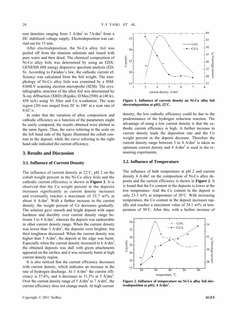
In order that the variation of alloy composition and cathodic efficiency as a function of the parameters might be easily compared, the results obtained were plotted in the same figure. Thus, the curve referring to the scale on the left hand side of the figure illustrated the cobalt con-tent in the deposit, while the curve referring to the right hand side indicated the current efficiency. 3. Results and Discussion 3.1. Influence of Current Density The influence of current density at 22˚C, pH 2 on the cobalt weight percent in the Ni-Co alloy foils and the cathodic current efficiency is shown in Figure 1. It is observed that the Co weight percent in the deposits increases significantly as current density increases and eventually reaches a maximum of 35.7 wt% at about 4 A/dm2. With a further increase in the current density, the weight percent of Co decreases gradually. The solution gave smooth and bright deposit with super hardness and ductility over current density range be-tween 3 to 4 A/dm2, whereas the deposit was undesirable in other current density range. When the current density was lower than 3 A/dm2, the deposits were brighter, but their toughness decreased. When the current density was higher than 5 A/dm2, the deposit at the edge was burnt. Especially when the current density increased to 6 A/dm2, the obtained deposits was dull with green attachments appeared on the surface and it was seriously burnt at high current density region.
It is also noticed that the current efficiency decreases with current density, which indicates an increase in the rate of hydrogen discharge. At 3 A/dm2, the current effi-ciency is 57.6%, and it decreases to 31.5% at 5 A/dm2. Over the current density range of 5 A/dm2 to 7 A/dm2, the current efficiency does not change much. At high current
Figure 1. Influence of current density on Ni-Co alloy foil electrodeposition at pH2, 22˚C. density, the low cathodic efficiency could be due to the predominance of the hydrogen reduction reaction. The advantage of using a low current density is that the ca-thodic current efficiency is high. A further increase in current density leads the deposition rate and the Co weight percent in the deposit decrease. Therefore the current density range between 3 to 4 A/dm2 is taken as optimum current density and 4 A/dm2 is used in the re-maining experiments.
3.2. Influence of Temperature
The influence of bath temperature at pH 2 and current density 4 A/dm2 on the composition of Ni-Co alloy de-posits and the current efficiency is shown in Figure 2. It is found that the Co content in the deposits is lower at the low temperature. And the Co content in the deposit is only 23.3 wt% at temperature of 20˚C. With increasing temperature, the Co content in the deposit increases rap-idly and reaches a maximum value of 34.1 wt% at tem-perature of 30˚C. After this, with a further increase of
Figure 2. Influence of temperature on Ni-Co alloy foil elec-trodeposition at pH2, 4 A/dm2.
Y. F. YANG ET AL.
Copyright © 2011 SciRes. ACES
29
temperature, the weight percent of Co in the deposits decreases gradually, however the decreased amount is smaller.
It is noticed that there is a steady increase in current efficiency with gradual increase in temperature. At 20˚C, the current efficiency is 27.6%, and it increases to 33.8% at 60˚C. In the mean time, the brightness of the deposits improves, the hydrogen evolution reaction weakens, the quality of the deposits is good and the thickness of the deposits increases. At temperature lower than 40˚C, a violent hydrogen evolution reaction takes place on the cathode, which consumes a considerable fraction of the current available and consequently makes the thickness of the deposits thinner. At temperature higher than 50˚C, the brightness of the deposit decreases and its compact-ness is worse. At 60˚C, the deposit is dull grey and brittle, accompanied by phenomenon of charred black with a large number of bubbles produced on the surface. So the optimum temperature range is 40 - 50˚C, at which the obtained deposits are bright and smooth.
3.3. Influence of pH Value
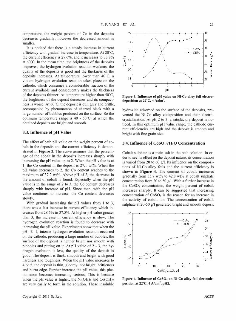
The effect of bath pH value on the weight percent of co-balt in the deposits and the current efficiency is demon-strated in Figure 3. The curve assumes that the percent-age of the cobalt in the deposits increases sharply with increasing the pH value up to 2. When the pH value is at 1, the Co content in the deposit is 27.1 wt%. When the pH value increases to 2, the Co content reaches to the maximum of 37.2 wt%. Above pH of 2, the decrease in the amount of cobalt is found. Especially when the pH value is in the range of 2 to 3, the Co content decreases sharply with increase of pH. Since then, with the pH value continues to increase, the Co content decreases slowly.
With gradual increasing the pH values from 1 to 3, there was a fast increase in current efficiency which in-creases from 28.5% to 37.5%. At higher pH value greater than 3, the increase in current efficiency is slow. The hydrogen evolution reaction is found to decrease with increasing the pH value. Experiments show that when the pH ≤ 1, intense hydrogen evolution reaction occurred on the cathode, producing a large number of bubbles, the surface of the deposit is neither bright nor smooth with pinholes and pitting on it. At pH value of 2 - 3, the hy-drogen evolution is less, the quality of the deposit is good. The deposit is thick, smooth and bright with good hardness and toughness. When the pH value increases to 4 or 5, the deposit is thin, gloomy, not bright, brittleness and burnt edge. Further increase the pH value, this phe-nomenon becomes increasing serious. This is because when the pH value is higher, the Ni(OH)2 and Co(OH)2 are very easily to form in the solution. These insoluble
Figure 3. Influence of pH value on Ni-Co alloy foil electro-deposition at 22˚C, 4 A/dm2. hydroxide adsorbed on the surface of the deposits, pre-vented the Ni-Co alloy codeposition and their electro-crystallization. At pH 2 to 3, a satisfactory deposit is no-ticed. In this optimum pH value range, the cathode cur-rent efficiencies are high and the deposit is smooth and bright with fine grain size.
3.4. Influence of CoSO4·7H2O Concentration
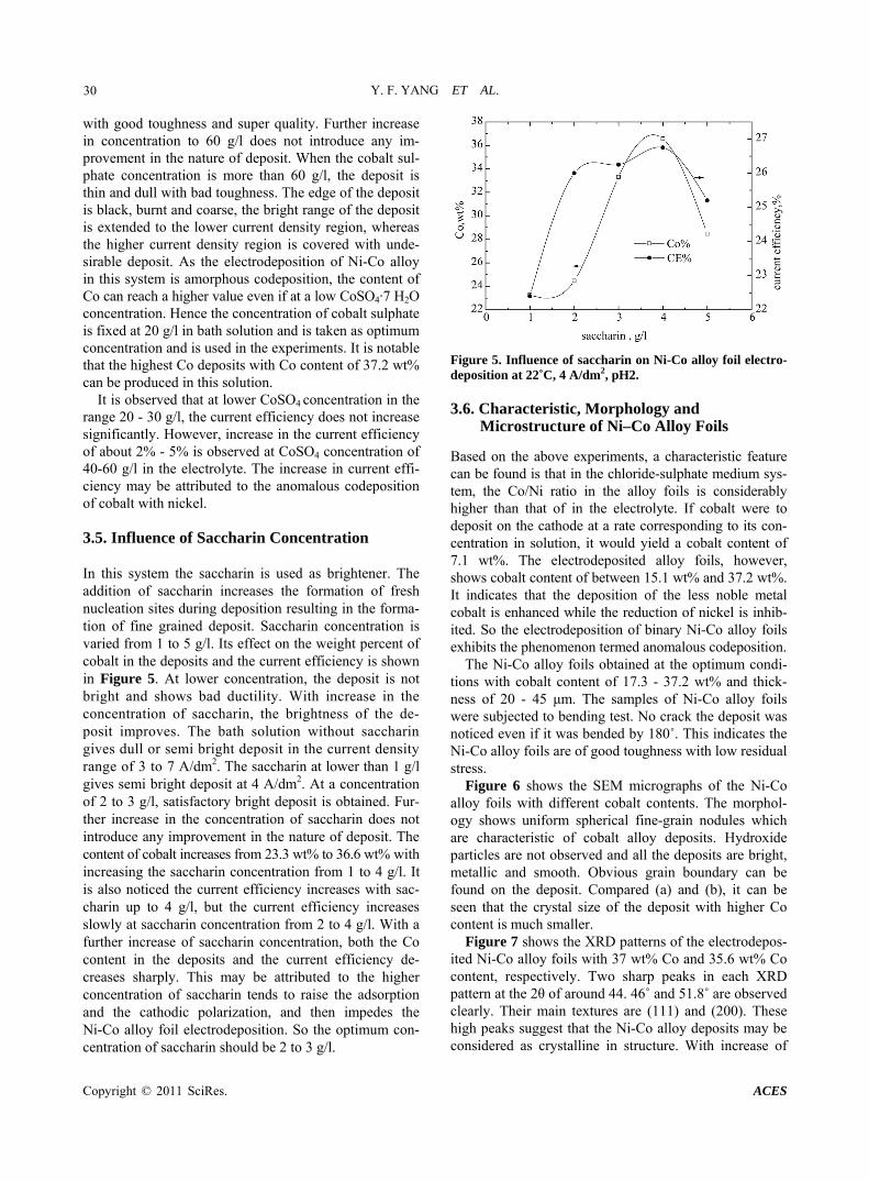
Cobalt sulphate is a main salt in the bath solution. In or-der to see its effect on the deposit nature, its concentration is varied from 20 to 60 g/l. Its influence on the composi-tions of Ni-Co alloy foils and the current efficiency is shown in Figure 4. The content of cobalt increases gradually from 35.7 wt% to 42.8 wt% at cobalt sulphate concentration from 20 to 50 g/l. With a further increase in the CoSO4 concentration, the weight percent of cobalt increases sharply. It can be suggested that increasing concentration of CoSO4 is the reason for an increase in the activity of cobalt ion. The concentration of cobalt sulphate at 20-50 g/l generated bright and smooth deposit
Figure 4. Influence of CoSO4 on Ni-Co alloy foil electrode-position at 22˚C, 4 A/dm2, pH2.
Y. F. YANG ET AL.
Copyright © 2011 SciRes. ACES
30
with good toughness and super quality. Further increase in concentration to 60 g/l does not introduce any im-provement in the nature of deposit. When the cobalt sul-phate concentration is more than 60 g/l, the deposit is thin and dull with bad toughness. The edge of the deposit is black, burnt and coarse, the bright range of the deposit is extended to the lower current density region, whereas the higher current density region is covered with unde-sirable deposit. As the electrodeposition of Ni-Co alloy in this system is amorphous codeposition, the content of Co can reach a higher value even if at a low CoSO4·7 H2O concentration. Hence the concentration of cobalt sulphate is fixed at 20 g/l in bath solution and is taken as optimum concentration and is used in the experiments. It is notable that the highest Co deposits with Co content of 37.2 wt% can be produced in this solution.
It is observed that at lower CoSO4 concentration in the range 20 - 30 g/l, the current efficiency does not increase significantly. However, increase in the current efficiency of about 2% - 5% is observed at CoSO4 concentration of 40-60 g/l in the electrolyte. The increase in current effi-ciency may be attributed to the anomalous codeposition of cobalt with nickel.
3.5. Influence of Saccharin Concentration
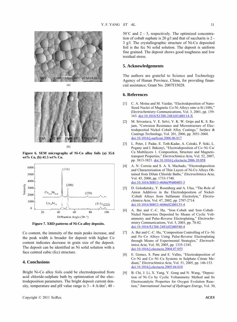
In this system the saccharin is used as brightener. The addition of saccharin increases the formation of fresh nucleation sites during deposition resulting in the forma-tion of fine grained deposit. Saccharin concentration is varied from 1 to 5 g/l. Its effect on the weight percent of cobalt in the deposits and the current efficiency is shown in Figure 5. At lower concentration, the deposit is not bright and shows bad ductility. With increase in the concentration of saccharin, the brightness of the de-posit improves. The bath solution without saccharin gives dull or semi bright deposit in the current density range of 3 to 7 A/dm2. The saccharin at lower than 1 g/l gives semi bright deposit at 4 A/dm2. At a concentration of 2 to 3 g/l, satisfactory bright deposit is obtained. Fur-ther increase in the concentration of saccharin does not introduce any improvement in the nature of deposit. The content of cobalt increases from 23.3 wt% to 36.6 wt% with increasing the saccharin concentration from 1 to 4 g/l. It is also noticed the current efficiency increases with sac-charin up to 4 g/l, but the current efficiency increases slowly at saccharin concentration from 2 to 4 g/l. With a further increase of saccharin concentration, both the Co content in the deposits and the current efficiency de-creases sharply. This may be attributed to the higher concentration of saccharin tends to raise the adsorption and the cathodic polarization, and then impedes the Ni-Co alloy foil electrodeposition. So the optimum con-centration of saccharin should be 2 to 3 g/l.
Figure 5. Influence of saccharin on Ni-Co alloy foil electro-deposition at 22˚C, 4 A/dm2, pH2.
3.6. Characteristic, Morphology and Microstructure of Ni–Co Alloy Foils
Based on the above experiments, a characteristic feature can be found is that in the chloride-sulphate medium sys-tem, the Co/Ni ratio in the alloy foils is considerably higher than that of in the electrolyte. If cobalt were to deposit on the cathode at a rate corresponding to its con-centration in solution, it would yield a cobalt content of 7.1 wt%. The electrodeposited alloy foils, however, shows cobalt content of between 15.1 wt% and 37.2 wt%. It indicates that the deposition of the less noble metal cobalt is enhanced while the reduction of nickel is inhib-ited. So the electrodeposition of binary Ni-Co alloy foils exhibits the phenomenon termed anomalous codeposition.
The Ni-Co alloy foils obtained at the optimum condi-tions with cobalt content of 17.3 - 37.2 wt% and thick-ness of 20 - 45 μm. The samples of Ni-Co alloy foils were subjected to bending test. No crack the deposit was noticed even if it was bended by 180˚. This indicates the Ni-Co alloy foils are of good toughness with low residual stress.
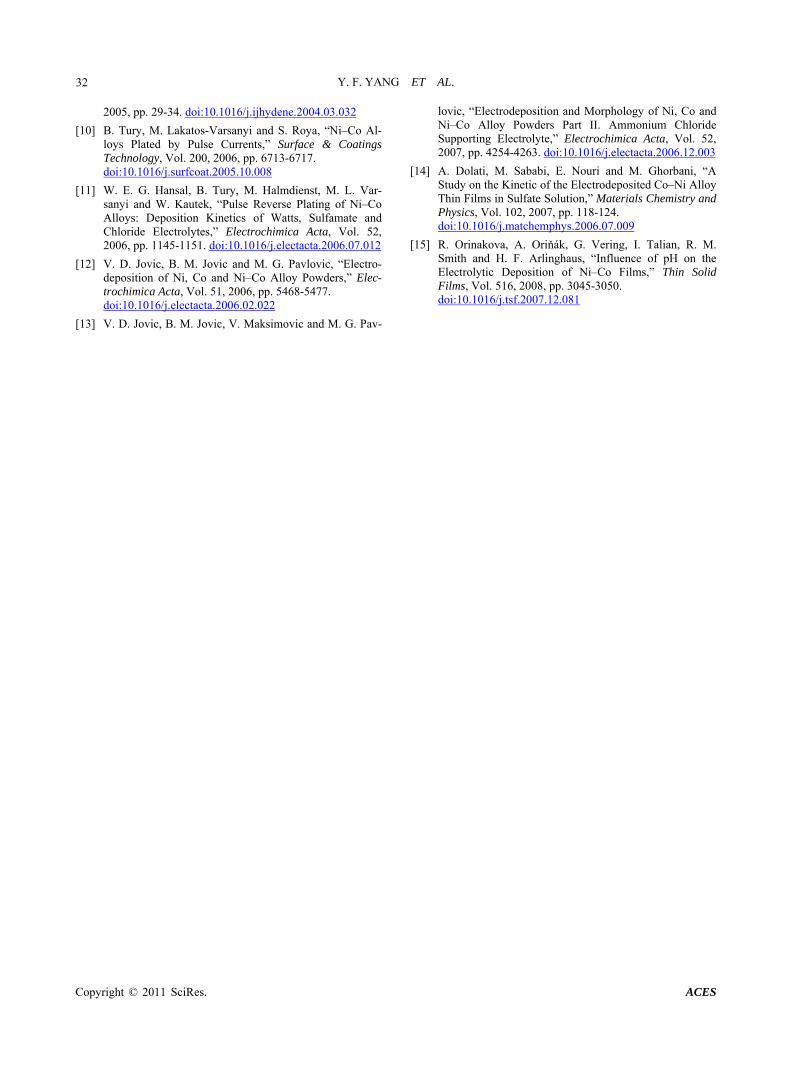
Figure 6 shows the SEM micrographs of the Ni-Co alloy foils with different cobalt contents. The morphol-ogy shows uniform spherical fine-grain nodules which are characteristic of cobalt alloy deposits. Hydroxide particles are not observed and all the deposits are bright, metallic and smooth. Obvious grain boundary can be found on the deposit. Compared (a) and (b), it can be seen that the crystal size of the deposit with higher Co content is much smaller.
Figure 7 shows the XRD patterns of the electrodepos-ited Ni-Co alloy foils with 37 wt% Co and 35.6 wt% Co content, respectively. Two sharp peaks in each XRD pattern at the 2θ of around 44. 46˚ and 51.8˚ are observed clearly. Their main textures are (111) and (200). These high peaks suggest that the Ni-Co alloy deposits may be considered as crystalline in structure. With increase of
Y. F. YANG ET AL.
Copyright © 2011 SciRes. ACES
31
(a)
(b)
Figure 6. SEM micrographs of Ni-Co alloy foils (a) 35.6 wt% Co, (b) 41.5 wt% Co.
Figure 7. XRD patterns of Ni-Co alloy deposits. Co content, the intensity of the main peaks increase, and the peak width is broader for deposit with higher Co content indicates decrease in grain size of the deposit. The deposit can be identified as Ni solid solution with a face centred cubic (fcc) structure.
4. Conclusions
Bright Ni-Co alloy foils could be electrodeposited from acid chloride-sulphate bath by optimization of the elec-trodeposition parameters. The bright deposit current den-sity, temperature and pH value range is 3 - 4 A/dm2, 40 -
50˚C and 2 - 3, respectively. The optimized concentra-tion of cobalt suphate is 20 g/l and that of saccharin is 2 - 3 g/l. The crystallographic structure of Ni-Co deposited foil is the fcc Ni solid solution. The deposit is uniform fine grained. The deposit shows good toughness and low residual stress.
5. Acknowledgements
The authors are grateful to Science and Technology Agency of Hunan Province, China, for providing finan-cial assistance; Grant No. 2007FJ3028.
6. References
[1] C. A. Moina and M. Vazdar, “Electrodeposition of Nano- Sized Nuclei of Magnetic Co-Ni Alloys onto n-Si (100),” Electrochemistry Communications, Vol. 3, 2001, pp. 159- 163. doi:10.1016/S1388-2481(01)00114-X
[2] M. Srivastava, V. E. Selvi, V. K. W. Grips and K. S. Ra-jam, “Corrosion Resistance and Microstructure of Elec-trodeposited Nickel–Cobalt Alloy Coatings,” Surface & Coatings Technology, Vol. 201, 2006, pp. 3051-3060. doi:10.1016/j.surfcoat.2006.06.017
[3] L. Peter, J. Padar, E. Toth-Kadar, A. Cziraki, P. Soki, L. Pogany and I. Bakonyi, “Electrodeposition of Co–Ni–Cu/ Cu Multilayers 1. Composition, Structure and Magneto-transport Properties,” Electrochimica Acta, Vol. 52, 2007, pp. 3813-3821. doi:10.1016/j.electacta.2006.10.058
[4] A. N. Correia and S. A. S. Machado, “Electrodeposition and Characterisation of Thin Layers of Ni-Co Alloys Ob-tained from Dilute Chloride Baths,” Electrochimica Acta, Vol. 45, 2000, pp. 1733-1740. doi:10.1016/S0013-4686(99)00405-3
[5] D. Golodnitsky, Y. Rosenberg and A. Ulus, “The Role of Anion Additives in the Electrodeposition of Nickel- /Cobalt Alloys from Sulfamate Electrolyte,” Electro-chimica Acta, Vol. 47, 2002, pp. 2707-2714. doi:10.1016/S0013-4686(02)00135-4
[6] A. Bai and C.-C. Hu, “Iron–Cobalt and Iron–Cobalt– Nickel Nanowires Deposited by Means of Cyclic Volt-ammetry and Pulse-Reverse Electroplating,” Electroche- mistry Communications, Vol. 5, 2003, pp. 78-82. doi:10.1016/S1388-2481(02)00540-4
[7] A. Bai and C.-C. Hu, “Composition Controlling of Co–Ni and Fe–Co Alloys Using Pulse-Reverse Electroplating through Means of Experimental Strategies,” Electroch- imica Acta, Vol. 50, 2005, pp. 1335-1345. doi:10.1016/j.electacta.2004.07.055
[8] E. Gomez, S. Pane and E. Valles, “Electrodeposition of Co–Ni and Co–Ni–Cu Systems in Sulphate–Citrate Me-dium,” Electrochimica Acta, Vol. 51, 2005, pp. 146-153. doi:10.1016/j.electacta.2005.04.010
[9] B. Chi, J. Li, X. Yang, Y. Gong and N. Wang, “Deposi-tion of Ni–Co by Cyclic Voltammetry Method and Its Electrocatalytic Properties for Oxygen Evolution Reac-tion,” International Journal of Hydrogen Energy, Vol. 30,
Y. F. YANG ET AL.
Copyright © 2011 SciRes. ACES
32
2005, pp. 29-34. doi:10.1016/j.ijhydene.2004.03.032
[10] B. Tury, M. Lakatos-Varsanyi and S. Roya, “Ni–Co Al-loys Plated by Pulse Currents,” Surface & Coatings Technology, Vol. 200, 2006, pp. 6713-6717. doi:10.1016/j.surfcoat.2005.10.008
[11] W. E. G. Hansal, B. Tury, M. Halmdienst, M. L. Var-sanyi and W. Kautek, “Pulse Reverse Plating of Ni–Co Alloys: Deposition Kinetics of Watts, Sulfamate and Chloride Electrolytes,” Electrochimica Acta, Vol. 52, 2006, pp. 1145-1151. doi:10.1016/j.electacta.2006.07.012
[12] V. D. Jovic, B. M. Jovic and M. G. Pavlovic, “Electro-deposition of Ni, Co and Ni–Co Alloy Powders,” Elec-trochimica Acta, Vol. 51, 2006, pp. 5468-5477. doi:10.1016/j.electacta.2006.02.022
[13] V. D. Jovic, B. M. Jovic, V. Maksimovic and M. G. Pav-
lovic, “Electrodeposition and Morphology of Ni, Co and Ni–Co Alloy Powders Part II. Ammonium Chloride Supporting Electrolyte,” Electrochimica Acta, Vol. 52, 2007, pp. 4254-4263. doi:10.1016/j.electacta.2006.12.003
[14] A. Dolati, M. Sababi, E. Nouri and M. Ghorbani, “A Study on the Kinetic of the Electrodeposited Co–Ni Alloy Thin Films in Sulfate Solution,” Materials Chemistry and Physics, Vol. 102, 2007, pp. 118-124. doi:10.1016/j.matchemphys.2006.07.009
[15] R. Orinakova, A. Oriňák, G. Vering, I. Talian, R. M. Smith and H. F. Arlinghaus, “Influence of pH on the Electrolytic Deposition of Ni–Co Films,” Thin Solid Films, Vol. 516, 2008, pp. 3045-3050. doi:10.1016/j.tsf.2007.12.081