Embed Size (px)
Citation preview
Communications
206 Ó WILEY-VCH Verlag GmbH, D-69469 Weinheim, 2000 0935-9648/00/0302-0206 $ 17.50+.50/0 Adv. Mater. 2000, 12, No. 3
±[1] C. J. T. Cronshaw, Endeavour 1942, 1, 79.[2] C. W. Tang, S. A. Van Slyke, Appl. Phys. Lett. 1987, 51, 913.[3] D. X. Wang, Y. Tanaka, M. Iizuka, S. Kuniyoshi, S. Kudo, K. Tanaka,
Jpn. J. Appl. Phys. 1999, 38, 256.[4] N. B. McKeown, Phthalocyanine Materials, Cambridge University
Press, Cambridge 1998.[5] F. Iwatsu, J. Phys. Chem. 1988, 92, 1678.[6] J. Janczac, R. Kubiac, J. Alloys Comp. 1992, 190, 121.[7] J. M. Robertson, J. Chem. Soc. 1936, 1195.[8] W. Kowalsky, T. Benstem, A. Bohler, S. Dirr, H.-H. Johannes, D.
Metzdorf, H. Neuner, J. Schöbel, P. Urbach, Phys. Chem. Chem. Phys.1999, 1, 1719.
[9] M. Ashida, N. Uyeda, E. Suito, J. Cryst. Growth 1971, 8, 45.[10] S. M. Bayliss, S. Heutz, G. Rumbles, T. S. Jones, Phys. Chem. Chem.
Phys. 1999, 1, 3673.[11] M. Ashida, N. Uyeda, E. Suito, Bull. Chem. Soc. Jpn. 1966, 39, 2616.[12] S. Matsumoto, K. Matsuhama, J. Mitzuguchi, Acta Cryst. C 1999, 55,
131.
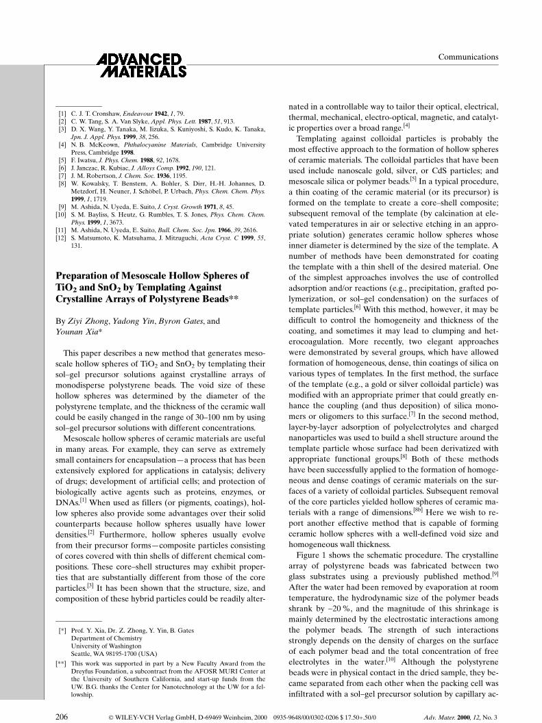
Preparation of Mesoscale Hollow Spheres ofTiO2 and SnO2 by Templating AgainstCrystalline Arrays of Polystyrene Beads**
By Ziyi Zhong, Yadong Yin, Byron Gates, andYounan Xia*
This paper describes a new method that generates meso-scale hollow spheres of TiO2 and SnO2 by templating theirsol±gel precursor solutions against crystalline arrays ofmonodisperse polystyrene beads. The void size of thesehollow spheres was determined by the diameter of thepolystyrene template, and the thickness of the ceramic wallcould be easily changed in the range of 30±100 nm by usingsol±gel precursor solutions with different concentrations.
Mesoscale hollow spheres of ceramic materials are usefulin many areas. For example, they can serve as extremelysmall containers for encapsulationÐa process that has beenextensively explored for applications in catalysis; deliveryof drugs; development of artificial cells; and protection ofbiologically active agents such as proteins, enzymes, orDNAs.[1] When used as fillers (or pigments, coatings), hol-low spheres also provide some advantages over their solidcounterparts because hollow spheres usually have lowerdensities.[2] Furthermore, hollow spheres usually evolvefrom their precursor formsÐcomposite particles consistingof cores covered with thin shells of different chemical com-positions. These core±shell structures may exhibit proper-ties that are substantially different from those of the coreparticles.[3] It has been shown that the structure, size, andcomposition of these hybrid particles could be readily alter-
nated in a controllable way to tailor their optical, electrical,thermal, mechanical, electro-optical, magnetic, and catalyt-ic properties over a broad range.[4]
Templating against colloidal particles is probably themost effective approach to the formation of hollow spheresof ceramic materials. The colloidal particles that have beenused include nanoscale gold, silver, or CdS particles; andmesoscale silica or polymer beads.[5] In a typical procedure,a thin coating of the ceramic material (or its precursor) isformed on the template to create a core±shell composite;subsequent removal of the template (by calcination at ele-vated temperatures in air or selective etching in an appro-priate solution) generates ceramic hollow spheres whoseinner diameter is determined by the size of the template. Anumber of methods have been demonstrated for coatingthe template with a thin shell of the desired material. Oneof the simplest approaches involves the use of controlledadsorption and/or reactions (e.g., precipitation, grafted po-lymerization, or sol±gel condensation) on the surfaces oftemplate particles.[6] With this method, however, it may bedifficult to control the homogeneity and thickness of thecoating, and sometimes it may lead to clumping and het-erocoagulation. More recently, two elegant approacheswere demonstrated by several groups, which have allowedformation of homogeneous, dense, thin coatings of silica onvarious types of templates. In the first method, the surfaceof the template (e.g., a gold or silver colloidal particle) wasmodified with an appropriate primer that could greatly en-hance the coupling (and thus deposition) of silica mono-mers or oligomers to this surface.[7] In the second method,layer-by-layer adsorption of polyelectrolytes and chargednanoparticles was used to build a shell structure around thetemplate particle whose surface had been derivatized withappropriate functional groups.[8] Both of these methodshave been successfully applied to the formation of homoge-neous and dense coatings of ceramic materials on the sur-faces of a variety of colloidal particles. Subsequent removalof the core particles yielded hollow spheres of ceramic ma-terials with a range of dimensions.[8b] Here we wish to re-port another effective method that is capable of formingceramic hollow spheres with a well-defined void size andhomogeneous wall thickness.
Figure 1 shows the schematic procedure. The crystallinearray of polystyrene beads was fabricated between twoglass substrates using a previously published method.[9]
After the water had been removed by evaporation at roomtemperature, the hydrodynamic size of the polymer beadsshrank by ~20 %, and the magnitude of this shrinkage ismainly determined by the electrostatic interactions amongthe polymer beads. The strength of such interactionsstrongly depends on the density of charges on the surfaceof each polymer bead and the total concentration of freeelectrolytes in the water.[10] Although the polystyrenebeads were in physical contact in the dried sample, they be-came separated from each other when the packing cell wasinfiltrated with a sol±gel precursor solution by capillary ac-
±
[*] Prof. Y. Xia, Dr. Z. Zhong, Y. Yin, B. GatesDepartment of ChemistryUniversity of WashingtonSeattle, WA 98195-1700 (USA)
[**] This work was supported in part by a New Faculty Award from theDreyfus Foundation, a subcontract from the AFOSR MURI Center atthe University of Southern California, and start-up funds from theUW. B.G. thanks the Center for Nanotechnology at the UW for a fel-lowship.

tion.[11] Again, this separation was presumably caused bythe repulsive electrostatic interactions among the chargedparticles.[10] Optical diffraction measurements indicate thatthe period of this three-dimensionally ordered arraychanged very little when the dispersion medium wasswitched from water to the sol±gel precursor solution.These results also suggest that the center-to-center distancebetween two adjacent beads was approximately the samein these two samples. When exposed to the moisture in air,the precursor hydrolyzed into metal oxide sols, which sub-sequently aggregated into a network of gel.[12] Before thesolvent evaporated completely, this gel precipitated outand formed a homogeneous, dense, thin coating aroundeach polystyrene bead. While the top substrate was still on,the cell was immersed in toluene to dissolve the polysty-rene template. Finally, the cell was disassembled, and theceramic hollow spheres were released from the substratesby sonication in a water bath.
The success of this method rests on a number of factorsassociated with this system. First, the polymer beads musthave an appropriate surface charge density, so their hydro-dynamic sizes can shrink by a certain magnitude upon dry-ing. In fact, this magnitude of shrinkage may limit the max-imum thickness of the ceramic coating on each polymerbead. Second, the polymer beads have to be confinedbetween two solid substrates. In this way, the ordered struc-ture of the crystalline array of polymer beads will be pre-served in the entire process, which includes water evapora-tion, infiltration of the precursor solution, formation ofsols, gelation, and drying. Because of this confinement, thethickness of the ceramic coating on each polymer bead willbe mainly determined by the amount of the liquid precur-sor around each polymer bead. If the samples are preparedfrom the same batch of polymer beads and with packingcells having the same thickness, the thickness of the ceram-ic coating on each polymer bead will only depend on the
concentration of the sol±gel precursor solution. Third, theresulting ceramic gel should be able to completely wet thesurface of the polymer bead. We note that the interfacialproperties of a polymer bead can be changed over a broadrange by a variety of approaches (e.g., direct surface treat-ment and formation of self-assembled monolayers) to ac-commodate sol±gel systems with different surface ten-sions.[13] Fourth, the gelation process has to be fast enoughthat a network of gel will be formed around the templateparticle before the solvent evaporates completely. Other-wise, the attractive interactions (e.g., capillary forces) asso-ciated with solvent evaporation may cause the polymerbeads to collapse into the closely packed form, and in thiscase, a three-dimensional porous structure of the ceramicmaterial will be formed.[14]
Figure 2 shows scanning electron microscopy (SEM)images of TiO2 hollow spheres that were formed by tem-plating a sol±gel precursor solutionÐtitanium(IV) isoprop-
Adv. Mater. 2000, 12, No. 3 Ó WILEY-VCH Verlag GmbH, D-69469 Weinheim, 2000 0935-9648/00/0302-0207 $ 17.50+.50/0 207
Communications
Fig. 1. Schematic outline of the experimental procedure. A cross-sectionalview of the cell is shown here.
Fig. 2. SEM images of hollow spheres of TiO2 that were generated by tem-plating a sol±gel precursor solution against a crystalline array of 380 nmpolystyrene beads. A) An array of TiO2 hollow spheres after the polystyreneparticles have been dissolved and the top substrate has been separated fromthe cell. B) A cross-sectional view of this array of hollow spheres, indicatingthe homogeneous thickness of the wall. C) A random aggregate of TiO2 hol-low spheres after they have been released from the substrates by sonicationin water. The arrow indicates a hollow sphere that has an opening in its sur-face.

Communications
208 Ó WILEY-VCH Verlag GmbH, D-69469 Weinheim, 2000 0935-9648/00/0302-0208 $ 17.50+.50/0 Adv. Mater. 2000, 12, No. 3
oxide in isopropanol, 1:19 (v/v)Ðagainst a crystalline as-sembly of 380 nm polystyrene beads. Figure 2A shows anarray of such hollow spheres after the polystyrene templatehas been dissolved by immersion in toluene and the topsubstrate has been separated from the cell. These hollowspheres exhibit a cubic close-packed (ccp) structure, whichis similar to that of the original template. Figure 2B showsthe SEM image of a cross-section of the crystalline assem-ble of hollow spheres. This section is parallel to the (111)face, and cuts through the equinoctial line of the hollowspheres. The void of these TiO2 hollow spheres is ~380 nmin diameter and the thickness of the wall is ~60 nm. Thehomogeneity in wall thickness, the physical contact amongadjacent hollow spheres, and the long-range order in thesample are clearly seen in these two SEM images. Fig-ure 2C shows the SEM image of a random aggregate ofTiO2 hollow spheres after they have been separated fromthe substrate by sonication in water, and redeposited ontoa silicon substrate, which served as the sample stage forSEM. The arrow indicates a hollow sphere that has a smallwindow in its surface. We note that the hollow structureand the spherical shape are largely preserved during theentire process.
We also examined the shape, structure, and wall thick-ness of the hollow spheres by transmission electron micros-copy (TEM). Figures 3A and 3B show TEM images of
TiO2 hollow spheres that were fabricated by templating asol±gel precursor solution (in isopropanol, 1:19, v/v) againsta crystalline array of 190 nm polystyrene beads. The voidof these hollow spheres is ~190 nm in diameter and theirceramic walls are ~50 nm in thickness. The thickness ob-tained from the TEM measurements is consistent with thevalue observed by SEM. Figure 3C gives the TEM imageof several dried 190 nm polystyrene beads. A comparisonof Figures 3B and 3C clearly indicates that the void size ofthe hollow spheres is essentially the same as the diameterof the polystyrene template that is measured by TEM ondried samples. The wall thickness of the hollow spheres, onthe other hand, depends on a number of parameters, suchas the hydrodynamic size of the template particle in water,the actual size of the template particle, and the concentra-tion of the sol±gel precursor solution. When samples areprepared from the same batch of polymer beads and inpacking cells with the same thickness, the wall thicknesswill be solely determined by the concentration of the sol±gel precursor solution. We have verified this assumption byusing samples packed from 380 nm polystyrene beads in12 mm thick cells. When sol±gel solutions with concentra-tions of 1:30, 1:20, and 1:10 were used, the wall thickness ofthe obtained TiO2 hollow spheres were ~30, ~60, and~100 nm, respectively.
We have also tried to extend this procedure to other sys-tems. Figure 4A shows the SEM image of SnO2 hollowspheres that were fabricated by templating a sol±gel pre-cursor solutionÐtetraisopropoxy tin(IV) isopropanol inethanol, 1:19 v/vÐagainst a crystalline array of 380 nmpolystyrene beads assembled in a 12 mm thick cell. These
Fig. 3. TEM images of TiO2 hollow spheres that were generated by templat-ing a sol±gel precursor solution against a crystalline array of 190 nm poly-styrene beads. The thickness of the wall is ~50 nm.
Fig. 4. A) An SEM image of SnO2 hollow spheres that were formed by tem-plating a sol±gel precursor solution against a crystalline array of 380 nmpolystyrene beads. These hollow spheres have been separated from sub-strates by sonication in a water bath. Some of them have openings in theirsurfaces. B) The SEM image of a SiO2 membrane that was formed when asol±gel precursor solution was templated against a crystalline array of380 nm polystyrene beads.

hollow spheres have been separated from the substrates bysonication in a water bath. As for the silica system, the useof a similar procedure only yielded a three-dimensionalporous network (Fig. 4B), rather than discrete hollowspheres. We believe part of the reason lies in the fact thatthe sol±gel reaction for the silica precursor (tetraethyl or-thosilicate in ethanol) is much slower than that of the TiO2
or SnO2 system.[12] As a result, the silica sols were unableto aggregate into a network of gel around the template par-ticle before the solvent evaporates completely. The silicasols only filled the void spaces among the polystyrenebeads of the crystalline array, and formed a three-dimen-sionally porous structures with an array of interconnectedspherical pores.
In summary, we have demonstrated an effective route tomesoscale hollow spheres of oxide ceramics such as TiO2
and SnO2. These hollow spheres have a well-defined voidsize that is determined by the diameter of the polystyrenetemplate, and a homogeneous wall whose thickness ismainly controlled by the concentration of the sol±gel pre-cursor solution. Although we only demonstrated this proce-dure with 190 and 380 nm polystyrene beads as examples,we believe that this method should be extendible to colloi-dal templates with smaller dimensions, and to hollowspheres made of other materials. The only requirementseems to be that a precursor solution is available and theresulting material can completely wet the surface of theparticle and thus form a uniform coating around the tem-plate before the solvent evaporates. This procedure canalso be applied to the fabrication of monodisperse, compos-ite particles consisting of cores covered with shells of differ-ent chemical compositions. The sizes and compositions ofthese core±shell particles can be changed in a controllableway to tailor their properties, such as optical, electrical, ormagnetic responses.
Experimental
Titanium(IV) isopropoxide (97 %) and tetraethyl orthosilicate (98 %)were obtained from Aldrich, and tetraisopropoxy tin(IV) isopropanol (98 %)was obtained from Gelest. All chemicals were used as received. We onlyused monodisperse polystyrene beads in the present work. The 190 nmbeads were obtained from Bangs Laboratory (Carmel, IN) and the 380 nmbeads were purchased from Polysciences (Warrington, PA). Prior to use, theaqueous dispersions of polymer beads were diluted to ~0.5 wt.-% with de-ionized water.
The packing cell was constructed from two glass substrates and a squareframe of photoresist (12 mm thick) [9], and tightened with binder clips. Oneside of the square frame had channels that were able to retain the particleswhile letting the solvent flow through. A hole (~3 mm in diameter) wasdrilled in the top glass substrate and a glass tube (~6 mm in diameter) wasattached to this hole using an epoxy adhesive. The aqueous dispersion ofmonodisperse polystyrene beads was injected into the cell through a rubbertube, and these beads were assembled into a crystalline array under continu-ous sonication and a slight positive pressure of nitrogen. After the water hasevaporated by drying in air for several days, the cell was placed in a glovebox (filled with nitrogen) and subsequently infiltrated with the sol±gel pre-cursor solution. When the cell was removed from the glove box, the sol±gelprecursor hydrolyzed into the oxide ceramics as a result of its exposure tothe moisture in air. While the top substrate was still on, the cell was im-mersed in toluene for ~10 h to dissolve the polystyrene beads. The hollow
spheres were released from the substrate by sonicating the sample in a waterbath for ~2 h.
The SEM measurements were conducted on a JEOL-6300F field-emis-sion microscope with an accelerating voltage of 15 kV. Before imaging, thesamples were sputtered with thin layers of gold. The TEM measurementswere carried out using a JEM-1200EX II microscope, with an acceleratingvoltage of 80 kV. The samples for TEM imaging were prepared by directlyplacing a drop of the aqueous dispersion of hollow spheres on carbon-coat-ed grids and letting the water evaporate slowly in air.
Received: September 13, 1999
±[1] a) E. Mathlowitz, J. S. Jacob, Y. S. Jong, G. P. Carino, D. E. Chicker-
ing, P. Chaturvedl, C. A. Santos, K. Vijayaraghavan, S. Montgomery,M. Bassett, C. Morrell, Nature 1997, 386, 410. b) H. Huang, E. E.Remsen, J. Am. Chem. Soc. 1999, 121, 3805.
[2] M. Ohmori, E. Matijevic, J. Colloid Interface Sci. 1992, 150, 594.[3] A. L. Aden, M. Kerker, J. Appl. Phys. 1951, 22, 1242.[4] a) A. P. Philipse, M. P. B. van Bruggen, C. Pathmananoharan, Lang-
muir 1994, 10, 92. b) S. Y. Chang, L. Liu, S. A. Asher, J. Am. Chem.Soc. 1994, 116, 6739. c) M. Giersig, T. Ung, L. M. Liz-Marzan, P.Mulvaney, Adv. Mater. 1997, 9, 570. d) R. D. Averitt, D. Sarkar, N. J.Halas, Phys. Rev. Lett. 1997, 78, 4217. e) H. Yao, Y. Takada, N.Kitamura, Langmuir 1998, 14, 595. f) S. J. Oldenburg, R. D. Averitt,S. L. Wetstcott, N. J. Halas, Chem. Phys. Lett. 1998, 288, 243. g) T.Ung, L. M. Liz-Marzan, P. Mulvaney, Langmuir 1998, 14, 3740.
[5] a) N. Kawahasji, E. Matijevic, J. Colloid Interface Sci. 1991, 143, 103.b) S. Y. Chang, L. Liu, S. A. Asher, J. Am. Chem. Soc. 1994, 116, 6745.c) D. Walsh, S. Mann, Nature 1995, 377, 320. d) M. Giersig, L. M. Liz-Marzan, T. Ung, D. Su, P. Mulvaney, Ber. Bunsenges. Phys. Chem.1997, 101, 1617. f) M. A. Correa-Duarte, M. Giersig, L. M. Liz-Mar-zan, Chem. Phys. Lett. 1998, 286, 497.
[6] a) A. Gary, E. Matijevic, J. Colloid. Interface Sci. 1988, 126, 243. b) N.Kawahashi, E. Matijevic, J. Colloid. Interface Sci. 1990, 138, 534. c) H.Bamnolker, B. Nitzan, S. Gura, S. Margel, J. Mater. Sci. Lett. 1997,1412. d) X.-C. Guo, P. Dong, Langmuir 1999, 15, 5535.
[7] L. M. Liz-Marzan, M. Giersig, P. Mulvaney, Chem. Commun. 1996,731. b) L. M. Liz-Marzan, M. Giersig, P. Mulvaney, Langmuir 1996,12, 4329.
[8] a) F. Caruso, H. Lichtenfeld, M. Giersig, H. Mohwald, J. Am. Chem.Soc. 1998, 120, 8523. b) F. Caruso, R. A. Caruso, H. Mohwald, Science1998, 282, 1111.
[9] a) S. H. Park, D. Qin, Y. Xia, Adv. Mater. 1998, 10, 1028. b) S. H. Park,Y. Xia, Langmuir 1999, 15, 266. c) B. Gates, D. Qin, Y. Xia, Adv.Mater. 1999, 11, 466.
[10] a) P. L. Flaugh, S. E. O'Donnell, S. A. Asher, Appl. Spectrosc. 1984,38, 847. b) N. Ise, Angew. Chem. Int. Ed. Engl. 1986, 25, 323. c) H. B.Sunkara, J. M. Jethmalani, W. T. Ford, Chem. Mater. 1994, 6, 362.d) C. A. Murray, D. G. Grier, Am. Sci. 1995, 83, 238. e) A. E. Larsen,D. G. Grier, Nature 1997, 385, 230.
[11] S. H. Park, Y. Xia, Adv. Mater. 1998, 10, 1045.[12] L. L. Hench, J. K. West, Chem. Rev. 1990, 90, 33.[13] R. Davies, G. A. Schurr, P. Meenan, R. D. Nelson, H. E. Bergna,
C. A. S. Brevett, R. H. Goldbaum, Adv. Mater. 1998, 10, 1264.[14] a) A. Imhof, D. J. Pine, Nature 1997, 389, 948. b) O. D. Velev, T. A.
Jede, R. F. Lobo, A. M. Lenhoff, Chem. Mater. 1998, 10, 3597. c) B. T.Holland, C. F. Blanford, A. Stein, Science 1998, 281, 538. d) J. E. G. J.Wijnhoven, W. L. Vos, Science 1998, 281, 802. e) P. Yang, T. Deng, D.Zhao, P. Feng, D. Pine, B. F. Chmelka, G. M. Whitesides, G. D. Stucky,Science 1998, 282, 2244.
Adv. Mater. 2000, 12, No. 3 Ó WILEY-VCH Verlag GmbH, D-69469 Weinheim, 2000 0935-9648/00/0302-0209 $ 17.50+.50/0 209
Communications
_______________________