Embed Size (px)
Citation preview
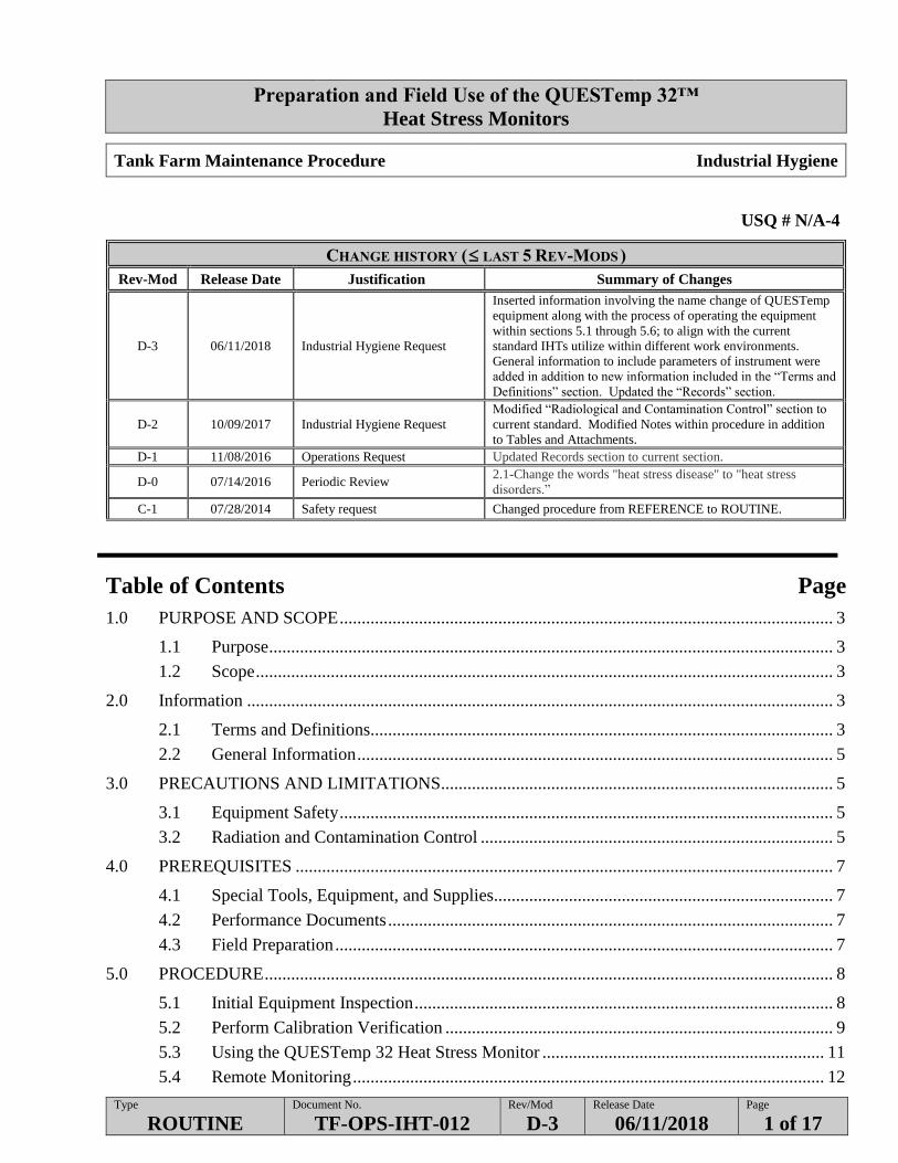
Preparation and Field Use of the QUESTemp 32™
Heat Stress Monitors
Type
ROUTINE Document No.
TF-OPS-IHT-012 Rev/Mod
D-3 Release Date
06/11/2018 Page
1 of 17
Tank Farm Maintenance Procedure Industrial Hygiene
USQ # N/A-4
CHANGE HISTORY ( LAST 5 REV-MODS )
Rev-Mod Release Date Justification: Summary of Changes
D-3 06/11/2018 Industrial Hygiene Request
Inserted information involving the name change of QUESTemp
equipment along with the process of operating the equipment
within sections 5.1 through 5.6; to align with the current
standard IHTs utilize within different work environments.
General information to include parameters of instrument were
added in addition to new information included in the “Terms and
Definitions” section. Updated the “Records” section.
D-2 10/09/2017 Industrial Hygiene Request
Modified “Radiological and Contamination Control” section to
current standard. Modified Notes within procedure in addition
to Tables and Attachments.
D-1 11/08/2016 Operations Request Updated Records section to current section.
D-0 07/14/2016 Periodic Review 2.1-Change the words "heat stress disease" to "heat stress
disorders.”
C-1 07/28/2014 Safety request Changed procedure from REFERENCE to ROUTINE.
Table of Contents Page
1.0 PURPOSE AND SCOPE ................................................................................................................ 3
1.1 Purpose ................................................................................................................................ 3
1.2 Scope ................................................................................................................................... 3
2.0 Information ..................................................................................................................................... 3
2.1 Terms and Definitions......................................................................................................... 3
2.2 General Information ............................................................................................................ 5
3.0 PRECAUTIONS AND LIMITATIONS......................................................................................... 5
3.1 Equipment Safety ................................................................................................................ 5
3.2 Radiation and Contamination Control ................................................................................ 5
4.0 PREREQUISITES .......................................................................................................................... 7
4.1 Special Tools, Equipment, and Supplies............................................................................. 7
4.2 Performance Documents ..................................................................................................... 7
4.3 Field Preparation ................................................................................................................. 7
5.0 PROCEDURE ................................................................................................................................. 8
5.1 Initial Equipment Inspection ............................................................................................... 8
5.2 Perform Calibration Verification ........................................................................................ 9
5.3 Using the QUESTemp 32 Heat Stress Monitor ................................................................ 11
5.4 Remote Monitoring ........................................................................................................... 12
Preparation and Field Use of the QUESTemp 32™
Heat Stress Monitors
Type
ROUTINE Document No.
TF-OPS-IHT-012 Rev/Mod
D-3 Release Date
06/11/2018 Page
2 of 17
5.6 Records ............................................................................................................................. 14
Attachment 1 Guidance for Establishing Work/Rest Regimens ............................................................... 15
Preparation and Field Use of the QUESTemp 32™
Heat Stress Monitors
Type
ROUTINE Document No.
TF-OPS-IHT-012 Rev/Mod
D-3 Release Date
06/11/2018 Page
3 of 17
1.0 PURPOSE AND SCOPE
1.1 Purpose
The purpose of this procedure is to ensure the proper use of the QUESTemp32™ heat
stress monitors in support of field monitoring performed in accordance with TF-OPS-
IHT-007, TFC-ESHQ-S_IH-C-07, and Heat Stress Mitigation Checklist.
1.2 Scope
The scope includes field calibration of the heat stress monitors and performing remote
monitoring as well as multiple sensor operation.
2.0 INFORMATION
2.1 Terms and Definitions
Heat Index (HI) – a measure of the dry bulb temperature and relative humidity to help
assess how the average person feels relative to climate conditions. It is a less exact
method for assessing the potential for heat stress disorders
Heat Strain - Physiological response to heat stress recognized by: increased core body
temperature, increased heart rate or sweating. If these responses are uncontrolled, these
symptoms may progress and result in increased incidence of heat stress disorders,
increased accident rates and irreversible physiological conditions.
Heat Stress - The net heat load on the body that results from exposure to external sources
and internal metabolic heat production due to physical work. It occurs when the body
produces or gains more heat than it is capable of giving off or losing. Contributing
environmental factors affecting the potential for heat stress include air temperature,
humidity, radiant heat exchange, and air movement. As heat stress approaches a worker’s
tolerance limits, the risk of heat related disorders increases.
Hot Environment – A work area where one or more of the following factors may exist,
creating the potential for heat stress: high temperature/humidity, sources of significant
radiant heat, use of protective clothing that insulates or impedes sweat evaporation, or dry
bulb temperatures in excess of 85°F.
Preparation and Field Use of the QUESTemp 32™
Heat Stress Monitors
Type
ROUTINE Document No.
TF-OPS-IHT-012 Rev/Mod
D-3 Release Date
06/11/2018 Page
4 of 17
2.1 Terms and Definitions (Cont.)
Rest Area – An area normally located as close to the worksite as possible, where workers
can periodically enter to cool down after working in hot environments. Areas should be
shaded, ventilated, have drinking water available, and allow worker to sit and partially
doff protective clothing when practical
Wet Bulb Globe Temperature (WBGT) – the weighted average of three temperatures
using environmental conditions to help assess the potential for heat stress disorders.
Indoor Wet Bulb Globe Temperature (WBGTin) – The weighted average of three
temperatures using environmental conditions to help assess the potential for heat stress
disorders utilized when a solar load (sun) is not present.
Outdoor Wet Bulb Globe Temperature (WBGTout) – The weighted average of three
temperatures using environmental conditions to help assess the potential for heat stress
disorders utilized when a solar load (sun) is present.
WBGT Meter – has three sensors that input data into a calculation that adjusts the
temperature to represent the impact humidity, wind and radiant heat have on heat strain
cooling effectiveness.
Preparation and Field Use of the QUESTemp 32™
Heat Stress Monitors
Type
ROUTINE Document No.
TF-OPS-IHT-012 Rev/Mod
D-3 Release Date
06/11/2018 Page
5 of 17
2.2 General Information
The QUESTemp 32 specifications and operating parameters:
Temperature sensor accuracy: + 0.9 F from 32 to 212 F
Verification module accuracy: ± 0.5°C
Operating temperature range:
Electronics- (23 – 140 F), Sensor Assembly (23 – 212 F)
Relative humidity:
0% - 100% (extended exposure to humidity > 90% can cause a reversible shift of
3%).
Battery life:
140 hours, 9V alkaline
Intrinsically safe:
Class 1, 2, 3, Division 1, Group A, B, C, D, E, F, G atmospheres, T3.
Weight: 2.6 lbs. with mounted sensor assembly
Cable length: 200 feet maximum without a decrease in accuracy
3.0 PRECAUTIONS AND LIMITATIONS
3.1 Equipment Safety
CAUTION - Improper connector pin alignment can result in damage to the connections.
CAUTION - The plugs or sockets marked “SENSOR 2” and “SENSOR 3” may not be
used within the hazardous area.
3.1.1 KEEP the unit away from anything that might block radiant heat or airflow.
3.1.2 PROTECT the unit if heavy rain or temperatures above 140 ºF (60 ºC) are
expected.
3.2 Radiation and Contamination Control
3.2.1 Planned work in radiological areas must be approved by Radiological Control
personnel per the Radiological Risk Screening procedure TFC-ESHQ-RP-
RWP-C-01.
3.2.1.1 When performed without a formal work package or approved
procedure (i.e., Level 3 or 4 work), this procedure is limited to
radiological areas and work activities permitted by a low risk
Radiological Work Permit (RWP).
Preparation and Field Use of the QUESTemp 32™
Heat Stress Monitors
Type
ROUTINE Document No.
TF-OPS-IHT-012 Rev/Mod
D-3 Release Date
06/11/2018 Page
6 of 17
3.2 Radiation and Contamination Control (Cont.)
3.2.2 Before conducting monitoring, contact the responsible Radiological Control
personnel for the facility or area to determine any specific survey or
monitoring requirements.
Pre, during, and post contamination survey requirements.
Any applicable Release Survey Plans (RSP) for your specific
equipment or task.
Alternative survey or monitoring needs to support the radiological
release survey process.
3.2.3 Comply with the requirements set forth by the RWP, HPT coverage, Release
Survey Plan (RSP), and any other applicable procedures as determined
above.
3.2.4 When exiting radiological areas where no HPT coverage was
provided, inform the radiological control personnel of the use/history for the
equipment being presented (e.g., only sampled air in the Contamination Area,
No known history of contamination based on use, etc.) to aid them in
properly evaluating the radiological release criteria needed.
Preparation and Field Use of the QUESTemp 32™
Heat Stress Monitors
Type
ROUTINE Document No.
TF-OPS-IHT-012 Rev/Mod
D-3 Release Date
06/11/2018 Page
7 of 17
4.0 PREREQUISITES
4.1 Special Tools, Equipment, and Supplies
The following supplies are/may be needed to perform this procedure:
Tripod
Wick for wet bulb
Verification Module
Time-keeping device (e.g., a watch or stopwatch)
Flat head screwdriver.
9-volt alkaline battery
Distilled or de-ionized water.
4.2 Performance Documents
The following documents may be needed to perform this procedure:
QUESTemp 32 Thermal Environmental Monitor Operator’s Manual
TFC-ESHQ-RP_RWP-C-03, “ALARA Work Planning”
TFC-ESHQ-S_IH-C-07, “Heat Stress Control”
TF-RC-043, “Perform Release Surveys for Material and Equipment.”
Heat Stress Mitigation Checklist (A-6006-431)
Industrial Hygiene WBGT Field Log (A-6004-079)
4.3 Field Preparation
4.3.1 ENSURE a review of the applicable Heat Stress Mitigation Checklist has
been completed.
Preparation and Field Use of the QUESTemp 32™
Heat Stress Monitors
Type
ROUTINE Document No.
TF-OPS-IHT-012 Rev/Mod
D-3 Release Date
06/11/2018 Page
8 of 17
5.0 PROCEDURE
5.1 Initial Equipment Inspection
5.1.1 CHECK that the maintenance calibration date on sticker is current.
5.1.2 IF calibration is past due, RETURN the monitor to the equipment custodian
with a completed green tag, “IH Instrument Service Tag” (BT-6004-019)
indicating it needs a “Scheduled Maintenance Calibration.”
5.1.3 INSPECT the unit and sensors to ensure the equipment has no physical
damage or missing pieces.
5.1.3.1 IF damage is found or unit appears unusable, RETURN the
damaged component(s) to the equipment custodian with a
completed green tag “IH Instrument Service Tag” (BT-6004-
019), documenting the condition.
5.1.4 TURN ON the QUESTemp 32 by pressing the “I/O ENTER” key.
NOTE - The display will indicate the status of the battery during the start-up cycle.
- The QUESTemp 32 can be powered using a 9-volt alkaline battery.
5.1.5 IF the battery voltage displayed during the power-on sequence is less than or
equal to 6.4 volts,
OR
IF “BAT” – low battery is displayed, REPLACE the batteries.
REPLACE the 9-volt alkaline battery as follows:
a. OPEN the battery door located in the back of the monitor
AND
REPLACE the old battery with a fresh 9-volt alkaline
battery.
b. ENSURE the 2-position switch located in the battery
compartment on the back of the monitor is in the UP
position for the 9-volt battery use.
Preparation and Field Use of the QUESTemp 32™
Heat Stress Monitors
Type
ROUTINE Document No.
TF-OPS-IHT-012 Rev/Mod
D-3 Release Date
06/11/2018 Page
9 of 17
5.2 Perform Calibration Verification
NOTE - Any active sensor assembly may follow these steps for calibration verification.
5.2.1 OBTAIN a verification module.
5.2.2 REMOVE the sensor assembly from the top of the monitor as follows:
5.2.2.1 PRESS AND UNSCREW (counterclockwise) the screws located
on the top of the monitor.
5.2.2.2 PULL the sensor assembly (mast) straight up from the base of
the monitor.
5.2.3 CHANGE the instrument (body) temperature reading unit as follows:
5.2.3.1 PRESS the “Setup” key until a temperature selection is
displayed.
5.2.3.2 PRESS “I/O Enter” to change from Fahrenheit to Celsius.
5.2.4 PRESS the “Setup” key to exit the setup mode.
CAUTION
Improper connector pin alignment can result in damage to the
connections.
5.2.5 PLUG the verification module into the 15-pin connector located on top of the
unit.
5.2.6 PRESS the UP or DOWN arrow AND
VERIFY that the readings on the monitor match the tolerance levels printed
on the side of the verification module within ±/0.5°C.
5.2.7 IF the readings are not within the 0.5°C tolerance, REPEAT calibration
verification
5.2.8 IF calibration verification is not successful, SELECT another verification
module and repeat steps 5.2.5 through 5.2.6.
5.2.9 IF third attempt at calibration verification is not successful, THEN
RETURN the monitor to the equipment custodian with a completed green
tag “IH Instrument Service Tag” (BT 6004-019) indicating “Function Check
Failure.”
Preparation and Field Use of the QUESTemp 32™
Heat Stress Monitors
Type
ROUTINE Document No.
TF-OPS-IHT-012 Rev/Mod
D-3 Release Date
06/11/2018 Page
10 of 17
5.2 Perform Calibration Verification (Cont.)
5.2.10 REMOVE the verification module from the top of the monitor.
5.2.11 RE-ATTACH the sensor assembly as follows:
5.2.11.1 PUSH the sensor assembly (mast) straight down on the base of
the monitor.
5.2.11.2 PRESS AND SCREW (clockwise) the screws located on the top
of the monitor
5.2.12 RESET the instrument to Fahrenheit as follows:
5.2.12.1 PERFORM steps 5.2.3.1 and 5.2.3.2 to change to Fahrenheit.
5.2.13 ENSURE that the wet bulb’s wick is clean.
5.2.14 IF the wet bulb wick is discolored, REPLACE the wick as follows:
5.2.14.1 SLIDE the old wick off of the sensor.
5.2.14.2 PLACE a new wick over the sensor ensuring that the bottom of
the wick is down in the reservoir.
NOTE - Do not use tap water. The contaminants that are left behind after evaporation
will shorten the life of the wick and cause high readings.
5.2.15 FILL the reservoir with distilled or de-ionized water.
5.2.16 ENSURE the wet bulb’s wick is fully wetted.
Preparation and Field Use of the QUESTemp 32™
Heat Stress Monitors
Type
ROUTINE Document No.
TF-OPS-IHT-012 Rev/Mod
D-3 Release Date
06/11/2018 Page
11 of 17
5.3 Using the QUESTemp 32 Heat Stress Monitor
NOTE - Steps 5.3.1 through 5.3.4 can be performed in any logical order.
5.3.1 TURN the monitor on.
5.3.2 PLACE the monitor in a location in the work area at a height of about 3 ½
feet for standing individuals or 2 feet for seated individuals.
5.3.3 CONFIRM the monitor display is set for the appropriate monitoring
environment, either WBGTin or WBGTout.
5.3.4 ALLOW 10 minutes for sensors to stabilize before taking reading when the
following conditions occur:
After adding water to the reservoir
When moving the monitor to a new environment.
5.3.5 KEEP the wick of the wet bulb thermometer wet with distilled water for at
least 10 minutes before a temperature reading is made.
NOTE - Standing close to the unit during monitoring could affect readings.
5.3.6 PERFORM heat stress monitoring in accordance with TFC-ESHQ-S_IH-C-
07.
5.3.6.1 RECORD the indoor or outdoor wet bulb globe temperature in
accordance with TFC-ESHQ-S_IH-C-46.
5.3.6.2 RECORD readings once each hour unless a different frequency
is directed by IH or the Heat Stress Mitigation Checklist.
5.3.7 ENSURE the wick is kept wet with distilled or de-ionized water.
5.3.8 WHEN monitoring is complete, TURN off the monitor
5.3.8.1 PRESS AND HOLD the “I/O ENTER” key while the unit goes
through a three second countdown and shuts off.
5.3.9 AFTER the survey, PERFORM a post-calibration verification by
performing Steps 5.2.1 through 5.2.10.
5.3.10 PROVIDE the completed field records to the IH within 2 working days.
Preparation and Field Use of the QUESTemp 32™
Heat Stress Monitors
Type
ROUTINE Document No.
TF-OPS-IHT-012 Rev/Mod
D-3 Release Date
06/11/2018 Page
12 of 17
5.4 Remote Monitoring
NOTE - Remote monitoring may be desired when it is necessary to protect the unit or
surveyor from but not limited adverse weather, radiological or logistical
conditions.
- The order of extension cable attachments to the sensor bar and monitor does
not matter.
- The QUESTemp 32 will operate with up to 200 feet of cable with no loss of
accuracy provided the environment does not contain a strong electromagnetic
field, which may cause interference.
5.4.1 OBTAIN a shielded extension cable.
5.4.2 REMOVE the top sensor from the monitor as follows:
5.4.2.1 PRESS down AND UNSCREW (counterclockwise) the screws
located on the top of the monitor
5.4.2.2 PULL the sensor assembly straight up from the base of the
monitor.
CAUTION
Improper connector pin alignment can result in damage to the
connections.
5.4.3 ATTACH the extension cable(s) to the desired port(s) on the monitor (e.g.,
ports 1 through3) and the 15-pin connector on the bottom of the sensor bar(s).
NOTE - Re-calibration of the WBGT is not required, this check is for continuity.
5.4.4 PLUG the verification module into the end of the extension cable to ensure
that the cord and sensor are working as a coupled unit.
5.4.5 REMOVE the verification module after determining the monitor, sensor
assembly and extension cord are responding.
NOTE - Be sure the tripod with sensor bar is in the area most representative of the
workforce being monitored.
5.4.6 Multiple tripods will be required when conducting remote monitoring;
SCREW the base of the monitor to a tripod using the threaded bushing on
the bottom,
5.4.7 SCREW the base of the sensor bar to another tripod using the threaded
bushing on the bottom.
Preparation and Field Use of the QUESTemp 32™
Heat Stress Monitors
Type
ROUTINE Document No.
TF-OPS-IHT-012 Rev/Mod
D-3 Release Date
06/11/2018 Page
13 of 17
5.5 Perform Multiple Sensor Operations
NOTE - Multiple sensors can be used in environments when the temperature in the
space surrounding a worker does not have a constant value and it is necessary
to determine the WBGT index at three heights, corresponding to the worker’s
ankles, abdomen and head, and perform a weighted average on those values.
- When more than one location is monitored during the same work evolution,
multiple sensors may be used e.g. inside a tent with sensor 2 and outside of
the tent with sensor 1.
- Only selected QUESTemp 32 heat stress monitors are configured to perform
multiple sensor operations and must be obtained from the equipment custodian
on an “as needed” basis.
5.5.1 CONSULT the responsible Industrial Hygienist (IH) for heat stress limits
and controls in this condition.
5.5.2 PLACE sensors, locating top sensor #1 at the abdomen level.
5.5.3 OBTAIN additional remote cables and sensor assemblies to attach to the
sensor ports located on the side of the monitor.
CAUTION
Improper connector pin alignment can result in damage to the
connections.
5.5.4 ENSURE that calibration verification has been performed on all active
sensor assembly locations per steps 5.2.1 through 5.2.10 prior to attaching
cables.
5.5.5 ATTACH cables to “SENSOR “2” and SENSOR “3” located on the side of
the instrument, THEN
ATTACH the opposite end of the cable to the additional sensor assemblies.
5.5.6 ATTACH the opposite end of the cable to the additional sensor assemblies.
5.5.7 INFORM employees working in the area being monitored what is being
measured and to be careful when moving and/or working around the monitor.
Preparation and Field Use of the QUESTemp 32™
Heat Stress Monitors
Type
ROUTINE Document No.
TF-OPS-IHT-012 Rev/Mod
D-3 Release Date
06/11/2018 Page
14 of 17
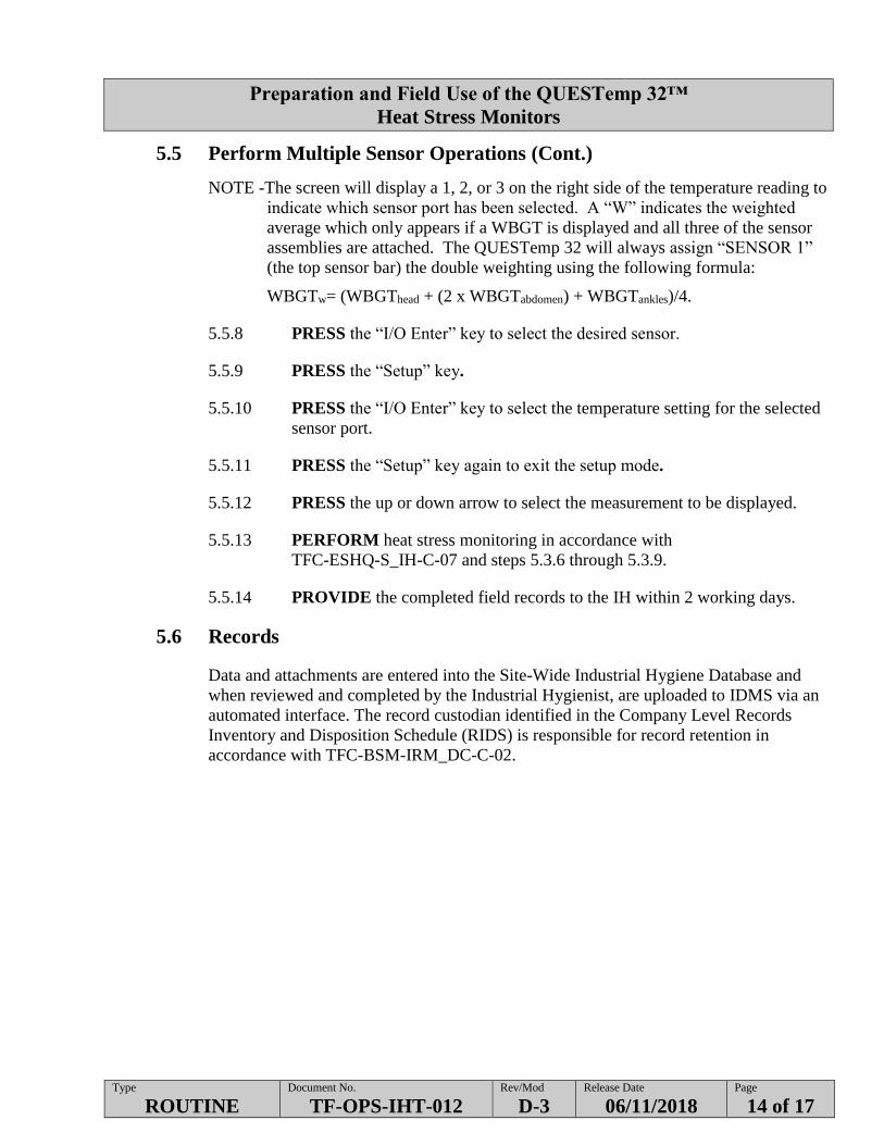
5.5 Perform Multiple Sensor Operations (Cont.)
NOTE -The screen will display a 1, 2, or 3 on the right side of the temperature reading to
indicate which sensor port has been selected. A “W” indicates the weighted
average which only appears if a WBGT is displayed and all three of the sensor
assemblies are attached. The QUESTemp 32 will always assign “SENSOR 1”
(the top sensor bar) the double weighting using the following formula:
WBGTw= (WBGThead + (2 x WBGTabdomen) + WBGTankles)/4.
5.5.8 PRESS the “I/O Enter” key to select the desired sensor.
5.5.9 PRESS the “Setup” key.
5.5.10 PRESS the “I/O Enter” key to select the temperature setting for the selected
sensor port.
5.5.11 PRESS the “Setup” key again to exit the setup mode.
5.5.12 PRESS the up or down arrow to select the measurement to be displayed.
5.5.13 PERFORM heat stress monitoring in accordance with
TFC-ESHQ-S_IH-C-07 and steps 5.3.6 through 5.3.9.
5.5.14 PROVIDE the completed field records to the IH within 2 working days.
5.6 Records
Data and attachments are entered into the Site-Wide Industrial Hygiene Database and
when reviewed and completed by the Industrial Hygienist, are uploaded to IDMS via an
automated interface. The record custodian identified in the Company Level Records
Inventory and Disposition Schedule (RIDS) is responsible for record retention in
accordance with TFC-BSM-IRM_DC-C-02.
Preparation and Field Use of the QUESTemp 32™
Heat Stress Monitors
Type
ROUTINE Document No.
TF-OPS-IHT-012 Rev/Mod
D-3 Release Date
06/11/2018 Page
15 of 17
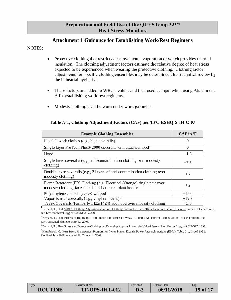
Attachment 1 Guidance for Establishing Work/Rest Regimens
NOTES:
Protective clothing that restricts air movement, evaporation or which provides thermal
insulation. The clothing adjustment factors estimate the relative degree of heat stress
expected to be experienced when wearing the protective clothing. Clothing factor
adjustments for specific clothing ensembles may be determined after technical review by
the industrial hygienist.
These factors are added to WBGT values and then used as input when using Attachment
A for establishing work rest regimens.
Modesty clothing shall be worn under work garments.
Table A-1, Clothing Adjustment Factors (CAF) per TFC-ESHQ-S-IH-C-07
Example Clothing Ensembles CAF in oF
Level D work clothes (e.g., blue coveralls) 0
Single-layer ProTech Plus® 2000 coveralls with attached hood4 0
Hood +1.8
Single layer coveralls (e.g., anti-contamination clothing over modesty
clothing) +3.5
Double layer coveralls (e.g., 2 layers of anti-contamination clothing over
modesty clothing) +5
Flame Retardant (FR) Clothing (e.g. Electrical (Orange) single pair over
modesty clothing, face shield and flame retardant hood)3 +5
Polyethylene coated Tyvek® w/hood1 +18.0
Vapor-barrier coveralls (e.g., vinyl rain suits) 2
Tyvek Coveralls (Kimberly 1422/1424) w/o hood over modesty clothing
+19.8
+3.0 1
Bernard, T., et al, WBGT Clothing Adjustments for Four Clothing Ensembles Under Three Relative Humidity Levels, Journal of Occupational
and Environmental Hygiene, 2:251-256, 2005. 2
Bernard, T., et al, Effects of Hoods and Flame Retardant Fabrics on WBGT Clothing Adjustment Factors, Journal of Occupational and
Environmental Hygiene, 5:59-62, 2008. 3
Bernard, T., Heat Stress and Protective Clothing: an Emerging Approach from the United States, Ann. Occup. Hyg., 43:321-327, 1999.
4Hornibrook, C., Heat Stress Management Program for Power Plants, Electric Power Research Institute (EPRI), Table 2-1, Issued 1991,
Finalized July 1998, made public October 1, 2008.
Preparation and Field Use of the QUESTemp 32™
Heat Stress Monitors
Type
ROUTINE Document No.
TF-OPS-IHT-012 Rev/Mod
D-3 Release Date
06/11/2018 Page
16 of 17
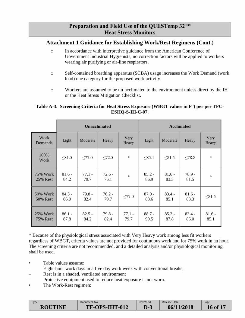
Attachment 1 Guidance for Establishing Work/Rest Regimens (Cont.)
o In accordance with interpretive guidance from the American Conference of
Government Industrial Hygienists, no correction factors will be applied to workers
wearing air purifying or air-line respirators.
o Self-contained breathing apparatus (SCBA) usage increases the Work Demand (work
load) one category for the proposed work activity.
o Workers are assumed to be un-acclimated to the environment unless direct by the IH
or the Heat Stress Mitigation Checklist.
Table A-3. Screening Criteria for Heat Stress Exposure (WBGT values in F°) per per TFC-
ESHQ-S-IH-C-07.
Unacclimated Acclimated
Work
Demands Light Moderate Heavy
Very
Heavy Light Moderate Heavy
Very
Heavy
100%
Work ≤81.5 ≤77.0 ≤72.5 * ≤85.1 ≤81.5 ≤78.8 *
75% Work
25% Rest
81.6 -
84.2 77.1 -
79.7 72.6 -
76.1 *
85.2 -
86.9 81.6 -
83.3 78.9 -
81.5 *
50% Work
50% Rest
84.3 -
86.0 79.8 -
82.4 76.2 -
79.7 ≤77.0
87.0 -
88.6 83.4 -
85.1
81.6 -
83.3 ≤81.5
25% Work
75% Rest
86.1 -
87.8 82.5 -
84.2 79.8 -
82.4 77.1 -
79.7 88.7 -
90.5 85.2 -
87.8 83.4 -
86.0 81.6 -
85.1
* Because of the physiological stress associated with Very Heavy work among less fit workers
regardless of WBGT, criteria values are not provided for continuous work and for 75% work in an hour.
The screening criteria are not recommended, and a detailed analysis and/or physiological monitoring
shall be used.
• Table values assume:
– Eight-hour work days in a five day work week with conventional breaks;
– Rest is in a shaded, ventilated environment
– Protective equipment used to reduce heat exposure is not worn.
• The Work-Rest regimen:
Preparation and Field Use of the QUESTemp 32™
Heat Stress Monitors
Type
ROUTINE Document No.
TF-OPS-IHT-012 Rev/Mod
D-3 Release Date
06/11/2018 Page
17 of 17
Attachment 1 Guidance for Establishing Work/Rest Regimens (Cont.)
Starts with the work phase followed by the rest phase (i.e., progress from 100% work to 75% work,
followed by 25% rest).
– Is evaluated hourly and adjusted as necessary (i.e., the work-rest phases, shall total no more than
1 hour in length).
• Rest areas should allow for a decrease in body core temperature via shade, cooling mechanisms,
removal of PPE, seating, fans, etc. when possible, in addition to proper hydration.