Embed Size (px)
Citation preview

Preparation and Characterization of Nickel and Limestone Based
Catalyst for Glycerol Dry Reforming
by
Nurul Amira Binti Amzah
13339
Dissertation submitted in partial fulfilment of
the requirements for the
Bachelor of Engineering (Hons)
(Chemical Engineering)
JANUARY 2014
Universiti Teknologi PETRONAS
Bandar Seri Iskandar
31750 Tronoh
Perak Darul Ridzuan

i
CERTIFICATION OF APPROVAL
Preparation and Characterization of Nickel and Limestone Based Catalyst for
Glycerol Dry Reforming
by
Nurul Amira Binti Amzah
A project dissertation submitted to the
Chemical Engineering Programme
Universiti Teknologi PETRONAS
in partial fulfillment of the requirement for the
BACHELOR OF ENGINEERING (Hons)
(CHEMICAL ENGINEERING)
Approved by,
______________________ (Dr. Bawadi Bin Abdullah)
UNIVERSITI TEKNOLOGI PETRONAS
TRONOH, PERAK
JANUARY 2014

ii
CERTIFICATION OF ORIGINALITY
This is to certify that I am responsible for the work submitted in this project, that the
original work is my own except as specified in the references and acknowledgements,
and that the original work contained herein have not been undertaken or done by
unspecified sources or persons.
_______________________ NURUL AMIRA AMZAH 910325-01-6346

iii
ABSTRACT
This project aims to study the preparation and characterization of nickel and
limestone based catalyst for glycerol dry reforming. This project comprises 2 parts.
The first part is to synthesise and characterize the nickel based catalyst and the
second part is to study effect of the different method of catalyst preparation of
limestone based catalyst on the surface area. Three nickel based catalysts supported
with different element which are Ni/CaO, Ni/Al2O3 and Ni/CeO2 for 20wt% nickel
has been synthesized. Besides that, limestone based catalyst also has been prepared
by using loading and doping method. The comparison of surface area of limestone
based catalyst; Ni/CaO has been done by characterized and analysed. All catalyst has
undergone the characterization step by using TPR, SAP, TEM, FESEM and EDX.
From the results, the reduction temperature of nickel oxide reduced to nickel is at
650 °C around 30 minutes. The BET surface area of NiO/Al2O3 are the highest
followed by NiO/CaO and NiO/CeO2. The TEM images of all three nickel based
catalyst shows that the particle diameter of the catalyst is inversely proportional to
the surface area. Thus, the particle diameter of Nickel supported with Alumina is
36.76nm, NiO/CaO is 42.5nm and NiO/CeO2 is 48.33nm. Other than that, the surface
area of limestone based catalyst using doping method in catalyst preparation
increasing 87% compared to loading method. This proves that the limestone based
catalyst is a promising candidate for dry reforming of glycerol.

iv
ACKNOWLEDGEMENT
This research was done in Universiti Teknologi PETRONAS (UTP) for the Final
Year Project (FYP) of degree level in Chemical Engineering program. Alhamdulillah,
thanks to Allah for giving me the opportunity to have a valuable experience in
experimental works and research.
First and for most, I would like to express my gratitude to my supervisor of this
project, Dr Bawadi bin Abdullah for his excellent guidance, support, patience and
encouragement throughout this project. Thank you for believing in me and give me
the opportunity to work with him such a very inspiring researcher.
I would like to acknowledge the laboratory facilities of this university which provide
the materials, equipment and workplace throughout the project. Thanks to all
laboratory technicians and also laboratory technologist for giving me support and
sharing valuable information and knowledge. Without them, my project can’t be
done in time period.
Moreover, I would like to thanks all my friends in Universiti Teknologi PETRONAS
especially Chemical Engineering students for their encouragement and support when
we facing the difficulties throughout the final year project.
Last but not least, my true appreciation is for my parents, Amzah Bin Othman and
Roseta Binti Ahmad for their love, understanding, and encouraging me with the best
wishes, cheering me up and stood by me from the beginning of this project until now.
Million thanks to my siblings, Mohd Amirul Hakim and Muhammed Amizan for
giving me spirit and unstoppable support in completing my degree. I love you all.
To all individuals who helped me directly or indirectly, thank you so much for your
kindness.

v
TABLE OF CONTENT
CERTIFICATION OF APPROVAL
CERTIFICATION OF ORIGINALITY
ABSTRACT
ACKNOWLEDGEMENT
LIST OF FIGURES
LIST OF TABLES
LIST OF ABBREVIATIONS
CHAPTER 1 : INTRODUCTION
1.1 Background study
1.2 Problem Statement
1.3 Objectives
1.4 Scope of work
CHAPTER 2 : LITERATURE REVIEW
2.1 Glycerol
2.2 Nickel
2.3 Limestone
2.4 Hydrogen Gas
2.5 Dry Reforming
2.6 Potential of Limestone as Based Catalyst
2.7 Catalyst Preparation
2.7.1 Impregnation
2.7.2 Co-Precipitation
2.7.3 Sol-Gel
CHAPTER 3 : METHODOLOGY
3.1 Process Flowchart
3.2 Catalyst Preparation Procedure
i
ii
iii
iv
vii
viii
viii
1
2
3
3
4
4
5
6
6
8
9
9
10
10
12
13
vi
3.3.1 Loading Method
3.3.2 Doping Method
3.3 Procedure for Standard Solution Preparation
3.4 Tools and Equipment
3.4.1 Chemical Used
3.4.2 Analytical Equipment Used
3.5 Gant Chart and Key Milestone
CHAPTER 4 : RESULT AND DISCUSSION
4.1 Catalyst Characterization
4.1.1 Nickel Based Catalyst
4.1.2 Limestone Based Catalyst
CHAPTER 5 : CONCLUSION AND RECOMMENDATION
CHAPTER 6 : REFERENCES
13
15
16
17
17
17
18
19
19
27
30
31

vii
LIST OF FIGURES
Figure 1 : Structure of glycerol. There is three hydroxyl group in glycerol………4
Figure 2 : Schematic diagram of different step in col-gel precipitate.……...…….11
Figure 3 : Process Flowchart……………………………………………………...12
Figure 4 : Preparation of 0.2g/ml Nickel Nitrate Hexahydrate standard solution...14
Figure 5 : Impregnation method…………………………………………………..14
Figure 6 : The solution was stirred for 1 hour with magnetic stirrer……………..14
Figure 7 : Catalyst after dried in oven……………………………………………14
Figure 8 : Catalyst was calcined in the furnace at 800°C………………………...14
Figure 9 : Catalyst after 5 hours of calcination…………………………………...14
Figure 10 : Gantt Chart of final year project…………………………………...….18
Figure 11 : TPR Profile for NiO/Al2O3……………………………………..……..21
Figure 12 : TPR profile for NiO/CaO…………………………………………...…22
Figure 13 : TPR Profile for NiO/CeO2………………………………………...…..23
Figure 14 : Adsorption isotherm comparison for all three catalyst………………..24
Figure 15 : TEM images under 100nm magnification……………………………...26
Figure 16 : FESEM images and EDX patterns for (a) NiO/CaO loading method.... 27
(b) NiO/CaO Doping Method
Figure 17 : Adsorption isotherm comparison for limestone based catalyst…..……28

viii
LIST OF TABLES
Table 1 : pH value of catalyst………………………………………………….....20
Table 2 : Analysis of Temperature-Reduction Programmed Reduction……….....21
Table 3 : Summary of SAP analysis for Nickel based catalyst…….……………..25
Table 4 : Summary of SAP analysis for Limestone Based Catalyst………..…….28
LIST OF ABBREVIATIONS
FYP Final Year Project
SAP Surface Area Analyzer & Porosimetry
TEM Transmission Electron Microscopy
TPR Temperature-Programmed Reduction
FESEM Field-Emission Scanning Electron Microscopy
EDX Electron Dispersed X-Ray
1
CHAPTER 1
INTRODUCTION
1.1 Background Study
Nowadays, fossils fuels have become the most important energy in our daily life. The
used of fossils fuels is not only limited to the certain industry but also the
applications in the petroleum industry and chemical sectors. Fossil fuel is one of non-
renewable sources that could not be regenerated or reproduced. Due to the reduction
of fossil fuel day by day, developing alternative sources of energy become a
considerable attention in the present scenario.
Recently, the production of biomass has become an intention and receives so much
interest as a source of renewable energy. One of the methods is by producing
hydrogen via biomass. Production of hydrogen via biomass has a potential to be
alternatives sources of renewable energy to replace the applications of fossil fuels in
industry. During a bio-diesel production process, the significant amount of glycerol
is produced as a by-product which has a high content of hydrogen. 10wt% of
glycerol will be produced in the transesterification process of bio-diesel which means
that every 1 tonne of manufactured bio-diesel, 100kg of glycerol are produced
throughout the process (Grey, 2001). The utilization of glycerol to produce hydrogen
or synthesis gas could potentially reduce the production costs of biodiesel (Hass et al,
2006).
Dry Reforming is one of the process for converting the glycerol to high value
product which is hydrogen. It is also known as Carbon Dioxide reforming.
Additionally, Carbon Dioxide involves in many hydrogen production technologies
relying on renewable energy (Jankhah, 2008). Thus, glycerol reforming with Carbon
Dioxide could be an attractive process. Since the bio-derived glycerol is considered
to be renewable, carbon dioxide neutral and glycerol will not contribute to the

2
greenhouse effect (Behr, 2008). Secondly, glycerol dry reforming will convert
Carbon dioxide into hydrogen or high value-added inert carbon and remove it from
the carbon biosphere cycle.
In this research the nickel and limestone based catalyst will be prepared. Nickel
Based catalyst is widely used in industry and has so much potential in producing
hydrogen. Meanwhile, limestone based catalyst are basically has the lower surface
area but according to Surahim et al (2012), limestone is a promising candidate of
based catalyst for hydrogen production via biomass
1.2 Problem Statement
There are only few studies about the catalyst used in glycerol dry reforming.
Therefore, the nickel and limestone based catalyst will be synthesized and
characterized perhaps can be useful in dry reforming of glycerol.
The surface area of the limestone based catalyst is low. In order to increase
the surface area of the catalyst, the doping method in catalyst preparation is
introduced. There is less studies applied the doping method in catalyst
preparation of hydrogen production via glycerol dry reforming. Usually, the
current research used loading method which comprises 3 steps which are
impregnation, calcination and reduction. In this project, the comparison of
surface area of limestone based catalyst by using doping and loading method
will be made.

3
1.3 Objectives
The main objective of this research is to carry out the study on preparation and
characterization of nickel and limestone based catalyst.
The specific objectives are:
.
To synthesize and characterize the nickel based catalyst.
To study the effects of different method in catalyst preparation to the surface
area of limestone based catalyst
1.4 Scope Of Work
The scope of work for this research are :
Synthesize 20wt% of Nickel Based Catalyst by using three different support
which is Alumina, Calcium Oxide and Ceria.
Synthesize Limestone Based Catalyst by using two different methods in
catalyst preparation which is Loading and Doping.
Analyze and characterize the nickel and limestone based catalyst by using
the analytical equipment such as Transmission Electron Microscopy (TEM),
Field-Emission Scanning Electron Microscopy (FESEM), Surface Area
Analyzer & Porosimetry (SAP), Temperature-Programmed Reduction (TPR)
and Electron Dispersed X-ray (EDX) for catalyst morphology and surface
area.
Compare the surface area of limestone based catalyst on different method of
catalyst preparation.

4
CHAPTER 2
LITERATURE REVIEW
2.1 Glycerol
Glycerol ( ) also refer as glycerin or 1,2,3 propanetriol is a colorless,
odorless, viscous liquid with sweet taste. Glycerol is widely used in various
applications such as pharmaceutical, cosmetics, toiletries, drugs and food products
(Pagliaro & Rossi, 2010). Glycerol has a specific gravity of 1.261, a melting point of
18.2 °C and a boiling point of 290 °C under normal atmospheric pressure. Besides
that, glycerol is a liquid organic compound of the alcohol family. Pagliaro and Rossi
(2010) stated that glycerol has three hydrophilic alcoholic hydroxyl groups which are
responsible for its solubility in water and its hygroscopic nature.
Figure 1 : Structure of glycerol. There is three hydroxyl group in glycerol
2.2 Nickel
Nickel is silvery-white. hard, malleable, and ductile metal. It is a good conductor of
heat and electricity. In its familiar compounds nickel is bivalent, although it assumes
other valences. It also forms a number of complex compounds. Most nickel
compounds are blue or green. Nickel dissolves slowly in dilute acids but, like iron,
becomes passive when treated with nitric acid. Finely divided nickel adsorbs
hydrogen.

5
Nickel Based catalyst are widely been applied in industry and widely used in
hydrogenation process to increase the reaction rate. The demands of nickel based
catalyst are increasing day by day for the process efficiencies Metals like platinum
and nickel make good catalysts because they adsorb strongly enough to hold and
activate the reactant (Clark, 2002). However, the platinum is costly compared to
nickel.
2.3 Limestone
Limestone is a sendimentary of rock composed mainly calcium carbonate ( ) in
the form of mineral calcite. Approximately 50% of weight composition in limestone
is Calcium Carbonate. The other substance composed in the limestone including the
small composition of clay minerals, quartz, pyrite, iron oxide and other minerals.
There is abundance of limestone in Malaysia. Basically the large occurrences of
limestone in Peninsular Malaysia are in the Klang Valley, Kinta Valley, Langkawi
Island, Gua Musang area and Pahang (Tan, 1998). The wide occurrences of
limestone make the substance easy to find and not much cost will be contributed.
Limestone will be used as based catalyst in this research. According to Surahim et al
(2012), they stated that the calcined limestone is a promising candidate of based
catalyst for hydrogen production process via biomass due to its availability and lower
cost compared to synthetic catalyst.
6
2.4 Hydrogen Gas
Hydrogen is chemical element which consists of 2 mole of hydrogen atom, ( ). It
is the most important and abundant element in the universe (Sorensen, 2005).
Hydrogen is the simplest molecules and it is incredibly light. Hydrogen is colorless
and odorless gas with no taste.
Nowadays, the hydrogen gas is one of the most important base-chemicals and is
mainly used in the production of ammonia based fertilizers (Hulteberg, 2011).
Hydrogen is a renewable energy and has been suggested as promising alternatives to
the fossil fuels. Currently, almost 95% of the world’s hydrogen is being produced
from fossil fuel based feedstock. The hydrogen productions are attractive options for
the future due to the lesser effects to the environment. Thus, it is important to find an
alternative way to regenerate hydrogen from biomass source as the hydrogen can be
used in various applications and will replace fossil fuels someday.
2.5 Dry Reforming
Dry Reforming or also known as Carbon Dioxide Reforming is a method of
producing synthesis gas from the reaction of carbon dioxide with hydrocarbon such
as methane and glycerol. In recent years, most of the researchers have been studied
about the dry reforming of methane and not much for dry reforming on glycerol.
Xiaodong et al (2009) have carried out the study of thermodynamic analysis of
glycerol dry reforming for syngas production. The objective is to understand the
possibility of glycerol dry reforming for hydrogen and synthesis gas production by
using Gibbs free energy minimization method. From the research, they can conclude
that the optimum conditions for hydrogen production are the temperature above
975K and to glycerol ratio of 1. Besides that, the production of synthesis gas
can reached the maximum with a temperature 1000K and to glycerol ratio of 1.
6.4 mol of syngas per one mole of glycerol will be produced with 33% conversion of
carbon dioxide under that condition.

7
Basically, the moles of hydrogen increase as the temperature increase when CGR is
less than 1. If the CGR is more than 1, the number of moles of hydrogen will
increase with the increasing of temperature until it reaches
the maximum conditions.
The suggestions of the main reaction for glycerol dry reforming by Xiaodong et al
(2010) are as follows:
C3H8O3 ⇌ 4H2+ 3CO (4)
CO + 3H2 ⇌ CH4 + H2O (5)
CO2+ 4H2 ⇌ CH4 + 2H2O (6)
CO2+ CH4 ⇌ 2H2+ 2CO (7)
CO + H2O ⇌ H2+ CO2 (8)
C + H2O ⇌ H2+ CO (9)
CH4 ⇌ 2H2 + C (10)
2CO ⇌ CO2+C (11)
C + 2H2O ⇌ 2H2+ CO2 (12)
Do Minh Tuan (2013) have conducted the experiment of syngas production from
glycerol via dry reforming method using limestone based catalyst. He used Gas
Chromatograph (GC) to determine the proportion of hydrogen, carbon monoxide and
unreacted carbon dioxide and hydrogen. From the result, the objective of experiment
was achieved as Hydrogen and Carbon Monoxide are two major components in the
gaseous product. Thus, we can conclude that, the dry reforming method for hydrogen
production via glycerol is a potential technique to convert glycerol to hydrogen.

8
2.6 Potential of Limestone as Based Catalyst
Limestone has a potential as based catalyst for hydrogen production as Surahim et al
(2012) used the limestone catalyst in hydrogen production from rice straw
gasification. They modified the limestone with an addition of transition metal
promoters such as Nickel, Ferum and Cobbalt. At the end of the research, Surahim et
al (2012) conclude that the modified limestone catalyst with Nickel as the metal
promoters gave the highest production of hydrogen with the favorable temperature
around 250-550 °C. However, the activity of the catalyst is more depending on the
promoters used rather than surface area of catalyst.
Other than that, the used of carbonaceous catalyst seems to be potentially ideal for
producing hydrogen or synthesis gas as the /CO ratio is close to 1 and the
emission is at very minimum range (Fernandez et al, 2010). Fernandez et al
(2010) compared three different methods in producing hydrogen which are pyrolysis,
steam reforming and dry reforming. The steam reforming generated the highest
production of hydrogen compared to the others method.
Moreover, the preparation of catalyst comprises of 3 major step which are
impregnation, drying and calcination as have been applied by Chawalit et al (2011)
in preparation of heterogeneous catalyst from limestone for transesterification of
vegetable oils. Thus, to characterize and prepare the limestone based catalyst, all the
step mention above will be done step by step.
In addition, the doping method will be added in catalyst preparation of limestone
based catalyst in order to compare the surface area of the active site of this catalyst.
The comparison either loading method or doping method give the higher surface area
to the limestone based catalyst will be determine in this research. The effects of the
catalyst preparation method also will be investigated. Do Minh Tuan (2013) used
Calcium Oxide (CaO) and Calcium Carbonate ( ) as the based catalyst as
limestone substance mainly consist of those element. During the preparation of
catalyst, the highest BET surface area of CaO and is 11.529
and 4.623
respectively. Thus, the doping method of catalyst preparation should be done in order

9
to investigate the comparison in surface area of loading and doping method in
catalyst preparation.
2.7 Catalyst Preparation
Methods of catalyst preparation arc very divcrsc and each catalyst may be produced
via different routes (Haber et al, 1995). Preparation usually involves continuous step.
Three main step in catalyst preparation are firstly, preparation of primary solid like
impregnation and precipitation. Secondly the processing of primary solid to obtain
catalyst precursor through heat treatment or calcination process and lastly the
activation of catalyst by reduction of metal oxide. There are three type of method in
preparation of primary solid or supported catalyst which are impregnation, co-
precipitation and sol-gel method.
2.7.1 Impregnation
Impregnation requires support is contacted with a certain amount of solution of the
metal precursor then its aged, dried and undergo the calcination step (Pinna, 1998).
In impregnation there are two methods of contacting which are incipient wetness and
wet impregnation (LePage et al, 1987). In incipient wetness impregnation or known
as ‘dry’ impregnation (Pinna, 1998) the volume of the solution containing the
precursor is equal or slightly less than the pore volume of the support. For example,
the impregnating solution which is salt is sprayed to the support which is under
stirring. The maximum loading is limited by the solubility of the precursor in the
solution.
The second method of impregnation is wet or known as soaking impregnation. Wet
impregnation requires the excess used of salt solution or metal precursor. After a
certain time the solid is separated and the excess solvent is removed by drying. For
both methods the operating variable is the temperature, which influences both the
precursor solubility and the solution viscosity and as a consequence the wetting time
(Campanati et al, 2003). The concentration profile of the impregnated compound
depends on the mass transfer conditions within the pores during impregnation and
drying.

10
2.7.2 Co-Precipitation
Co-precipitation method requires the solutions containing metal salt and a salt of a
compound that will be converted into the support. In order to get the hydroxide or
carbonate precipitate, the solution is contacted under stirring with a base (Pinna,
1998). After washing, these can be transformed to oxides by heating in calcination
step. This method usually used in large scale of production such as steam reforming.
The typical catalysts prepared by using this method are Ni/Al2O3 and Cu-Zn
Oxide/Alumina. By co-precipitation a uniform distribution on a molecular scale of
the different active species in the final catalyst could be attained. During the
preparation, many variables have to be controlled; efficient mixing, temperature,
order of addition solutions and ageing time of catalyst precipitate (Pinna, 1998). All
of these factors must take into account in order to get more appropriate catalyst.
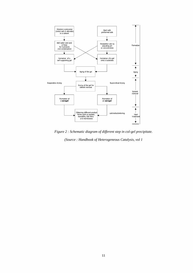
2.7.3 Sol-gel
The sol–gel method or known as gelation route is a homogeneous process which
results in a continuous transformation of a solution into a hydrated solid precursor
which known as hydrogel. Sol–gel methods have several promising advantages over
precipitation. In general, sol–gel syntheses have been recognized for their flexibility
which allows better control of the texture, composition, homogeneity and also
structural properties of the final solids. The nanoscale chemistry involved in sol–gel
methodsis a more direct way to prepare highly divided materials (Perego & Villa,
1997). During sol-gel preparation, four main steps may be identified in taking a
precursor to a particular product which are formation of a hydrogel, its ageing,
removal of solvent and heat treatment in calcination process.
11
Figure 2 : Schematic diagram of different step in col-gel precipitate.
(Source : Handbook of Heterogeneous Catalysis, vol 1

12
CHAPTER 3
METHODOLOGY
3.1 Process Flowchart
Figure 3: Process Flowchart
Three (3) types of nickel based catalyst will be prepared to carry out these
experiments which are Ni/ , Ni/CeO2 and Ni/CaO. In addition, the Alumina
(Al) support will be the reference for this experiment. As mention in above section,
there will be 2 methods in catalyst preparation which are loading technique and
doping technique. Only limestone based catalyst will be applied on doping technique.
Another 2 catalyst will be prepared for doping method which are NiO/CaO contain
4wt% of nickel. After the preparation of catalyst, all five catalysts will be
characterized by using the following method:
Analysis of catalyst.
Catalyst characterization (Limestone Based Catalyst)
Catalyst Characterization (Nickel Based Catalyst)
Catalyst Preparation 1. Loading 2. Doping
Studying on existing method in preparation of catalyst.
Study on existing Method producing Hydrogen

13
i) BET Analysis – to determine the surface area of the catalyst
ii) Transmission Electron Microscopy (TEM) – to examine the pore size of the
catalyst.
iii) Field-Emission Scanning Electron Microscope (FESEM)- to determine the
morphology of the catalyst.
3.2 Catalyst Preparation Procedure
3.2.1 Loading Method
This procedure is for 20wt% of Nickel.
1. The 100ml of 0.2g/ml of standard solution of Ni(NO3)2.6H2O was prepared
by using 99.08g Ni(NO3)2.. (Figure 4)
2. By using 10g basis, 8g of Al2O3 /CaO / Ce powder was put in the beaker.
3. 10ml of Ni(NO3)2.6H2O solution was added on the powdered Al2O3 /CaO /
Ce by using pipette/burette. The solution was stirred at the same time.
(Figure 5)
4. 20ml of deionized water was added to the solution and the solution was
stirred for 1 hour with magnetic stirrer at 300rpm at room temperature. The
function of deionized water is to facilitate the stirring process. (Figure 6)
5. The pH of the solution was checked by using pH meter in the laboratory.
6. The catalyst was dried in oven at 90oC for 20hours. (Figure 7)
7. The catalyst was calcined at 800oC for 5hours with heating rate of 5
oC/min.
(Figure 8)
8. The catalyst was stored in desiccator and will be used in the experiment.
9. The procedure was repeated for 4wt% of Nickel for limestone based catalyst.

14
Figure 4 Preparation of 0.2g/ml Nickel
Nitrate Hexahydrate standard solution.
Figure 5 Impregnation method
Figure 6 The solution was stirred for 1
hour with magnetic stirrer
Figure 7 Catalyst after dried in oven.
Figure 8 : Catalyst was calcined in the
furnace at 800C
Figure 9 Catalyst after 5 hours of
calcination
15
3.2.2 Doping Method
4 wt% of CaO will be used in this doping method in order to compare with
loading method. Here are the procedure :
1. 1.92g of Calcium Oxide (CaO) was mixed with 40ml of deionized water to
the Teflon autoclave.
2. The solution was stirred for 1 hour by using magnetic stirrer.
3. The pH of the solution was checked by using pH meter. The pH must be
greater than 6.75. If not, the solution will be adjusted by using dropwise
addition of sodium hydroxide or aqueous ammonia solution.
4. 0.638g of nickel nitrate hexahydrate, Ni(NO3)2.6H2O was added to the Teflon
autoclave and stirred it for 3 hours at room temperature.
5. The Teflon autoclave was sealed and kept in oven for 24 hours at 100°C.
6. Collect the precipitate from autoclave after cool it to room temperature.
7. The product was recovered by filtration, washes the precipitate with
deionized water and dried at room temperature for 12 hours.
8. The Ni-doped will be obtained by calcining the catalyst at 600°C for 5 hours
at 5°C/min.

16
3.3 Procedure For Standard Solution Preparation
1. Weighted the amount of chemicals Ni(NO3)2.6H2O needed and dissolved with
deionized water.
2. Sample calculation for amount of chemicals needed:-
(a) Preparation 0.2g/ml of Ni
MW of Ni(NO3)2.6H2O = 290.79 g/mol
MW of Ni = 58.6934g/mol
For 100ml of solution, need 20g of Ni
Amount of Ni(NO3)2 needed =
x 290.79
= 99.09 g Ni(NO3)2.6H2O
(b) 20 wt% of Ni
MW of Ni(NO3)2.6H2O = 290.79 g/mol
MW of Ni = 58.6934g/mol
For 10g basis, mass of Ni= 2 g, Al2O3 = 8 g
0.2g/ml x amount of Ni(NO3)2.6H2O = 4 g Ni
Amount of Ni(NO3)2.6H2O =
= 10 ml for 20wt% of Ni

17
3.4 Tools And Equipment
3.4.1 Chemical Used
Below are the raw materials and chemicals that are required in this experiment
1. Nickel Nitrate Hexahydrate (Ni(NO3)2.H2O)
2. Calcium Oxide )
3. Aluminium Oxide ( )
4. Deionized Water
5. Carbon Dioxide )
6. Hydrogen (H2)
7. Nitrogen (N2)
3.4.2 Analytical Equipment Used
There are five equipment required to analyze the catalyst and gas produce throughout
the experiment. Below are the analytical equipment used in this project :
1. Temperature-Programmed Reduction (TPR)
2. Surface Area Analyzer & Porosimetry (SAP)
3. Transmission Electron Microscope (TEM)
4. Field Emission Scanning Electron Microscope (FESEM)
5. Electron Dispersed X-Ray (EDX)

18
3.5 Gantt Chart And Key Milestone
Project activities
Week No
MAY JUNE JULY AUG SEPT OCT NOV DEC/JAN
1 2 3 4 5 6 7 8 9 10 11 12 13 14 1 2 3 4 5 6 7 8 9 10 11 12 13 14 15
Selection of project topic
Preliminary research work
Submission of extended proposal •
Proposal defence
Fine-tuning research methodology
Submission of interim draft report •
Submission of interim report •
Arrival of experimental apparatus •
Catalyst Preparation
Submission of progress report •
Data post-processing
Data analysis and documentation
Pre-SEDEX •
Submission of draft report •
Submission of dissertation •
Submission of technical paper •
Oral presentation •
Submission of project dissertation
Figure 10: Gantt Chart of final year projec

19
CHAPTER 4
RESULT AND DISCUSSION
4.1 Catalyst Characterization
At the beginning of November, 5 sample of catalyst have been prepared successfully
until calcination step. There are 2 method in preparing the catalyst which is loading
method and doping method. The catalyst prepared is as below with its simplified
name:
1. Nickel Oxide supported with Aluminum Oxide 20wt% (NiO/Al2O3)
2. Nickel Oxide supported with Calcium Oxide 20wt% (NiO/CaO)
3. Nickel Oxide supported with Cerium Oxide 20wt% (NiO/CeO2)
4. Nickel Oxide supported with Calcium Oxide 4 wt% (NiO/CaO Loading)
5. Nickel Oxide supported with Calcium Oxide 4 wt% (NiO/CaO Doping)
The results were obtained with Temperature-Programmed Reduction (TPR), Surface
Area and Porosimetry (SAP) Analyzer, Transmission Electron Microscopy (TEM)
analysis, and Field-Emission Scanning Electron Microscopy (FESEM) analysis.
In this section, the morphologies of catalyst will be discussed based on the analysis
results of FESEM and TEM. SAP analysis give the information on the BET surface
area, pore size, pore volume and particle diameter which will be useful in analyzing
the catalytic activity of catalyst in dry reforming of glycerol. Other than that, the
TPR analysis will give the information on reduction temperature as well as the time
to reduce oxide from the precursor that will be useful while doing the dry reforming
application.
20
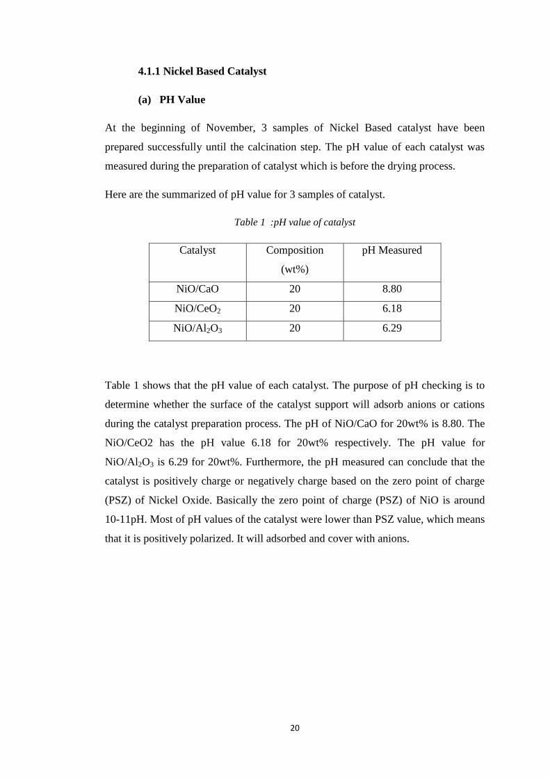
4.1.1 Nickel Based Catalyst
(a) PH Value
At the beginning of November, 3 samples of Nickel Based catalyst have been
prepared successfully until the calcination step. The pH value of each catalyst was
measured during the preparation of catalyst which is before the drying process.
Here are the summarized of pH value for 3 samples of catalyst.
Table 1 :pH value of catalyst
Catalyst Composition
(wt%)
pH Measured
NiO/CaO 20 8.80
NiO/CeO2 20 6.18
NiO/Al2O3 20 6.29
Table 1 shows that the pH value of each catalyst. The purpose of pH checking is to
determine whether the surface of the catalyst support will adsorb anions or cations
during the catalyst preparation process. The pH of NiO/CaO for 20wt% is 8.80. The
NiO/CeO2 has the pH value 6.18 for 20wt% respectively. The pH value for
NiO/Al2O3 is 6.29 for 20wt%. Furthermore, the pH measured can conclude that the
catalyst is positively charge or negatively charge based on the zero point of charge
(PSZ) of Nickel Oxide. Basically the zero point of charge (PSZ) of NiO is around
10-11pH. Most of pH values of the catalyst were lower than PSZ value, which means
that it is positively polarized. It will adsorbed and cover with anions.

21
(b) Temperature-Programmed Reduction
TPR measurement were carried out in a conventional flow system with a moisture
trap connected to a Thermal Conductivity Detector (TCD) at temperature ranging
from room temperature until 900°C. A mixed stream of Hydrogen and Nitrogen was
used. For this project, the temperature was raised up to 800°C with heating rate of
20°C/min. The holding time was set for 30min. Table below are the summarized of
the report of the TPR measurement for 20wt% of nickel.
Table 2: Analysis of Temperature-Reduction Programmed Reduction
Type of
Catalyst
Mass (g) Amount Gas
absorbed
(μmol/g)
Total
Metal
Surface
(m2)
Dispersion
Degree
(%)
Mean
Particle
Diameter
(nm)
NiO/Al2O3 0.0542 1848.31 3.921 54.248 1.864
NiO/CaO 0.0433 1854.97 3.144 54.443 1.857
NiO/CeO2 0.0993 2600.09 10.107 76.313 1.325
Figure 11 : TPR profile for NiO/Al2O3.
973971
60
Time ( min )0 20 40 60
3000
Sig
na
l (
mV
)
0
1000
2000
3000
800
Te
mp
era
ture
( °
C )
0
200
400
600
800
22
Figure 11 shows that the signal is indicate the hydrogen uptake or absorb by the
catalyst. There are 2 peaks that can be seen in the above figure which occur at 500°C
and 700°C for 1500mV and 2500mV hydrogen uptake respectively. At minutes of 20,
the temperature start to increase until it reaches 600°C and decrease after minutes of
30. The hydrogen uptake is directly proportional to the temperature. As the
temperature increases the absorption of hydrogen to the catalyst also will increase.
Besides that, the first peak occur around 500°C possibly because of the nickel oxide
not completely reduce to the nickel metal. Therefore, the reduction temperature for
NiO/Al2O3 is at 650°C and for 30minutes.
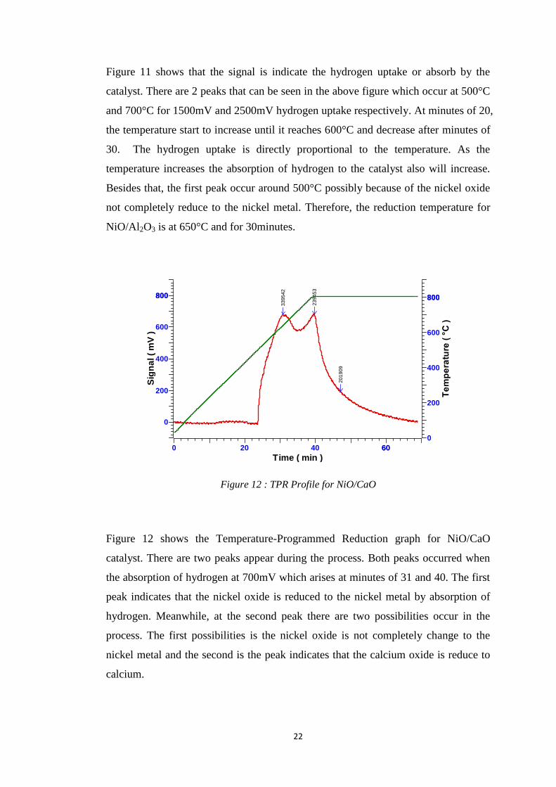
Figure 12 : TPR Profile for NiO/CaO
Figure 12 shows the Temperature-Programmed Reduction graph for NiO/CaO
catalyst. There are two peaks appear during the process. Both peaks occurred when
the absorption of hydrogen at 700mV which arises at minutes of 31 and 40. The first
peak indicates that the nickel oxide is reduced to the nickel metal by absorption of
hydrogen. Meanwhile, at the second peak there are two possibilities occur in the
process. The first possibilities is the nickel oxide is not completely change to the
nickel metal and the second is the peak indicates that the calcium oxide is reduce to
calcium.
339542
239453
201909
60
Time ( min )0 20 40 60
800
Sig
na
l (
mV
)
0
200
400
600
800 800
Te
mp
era
ture
( °
C )
0
200
400
600
800

23
Figure 13 : TPR profile for NiO/CeO2
Figure 13 shows that the highest hydrogen uptake for NiO/CeO2 catalyst is 4500mV
at 25 minutes. the NiO/CeO2 shows two clear peak. The first peak occurs at 450°C
and second peak at 600°C. The oxide from Ceria may reduce to be Ce2O3 during the
first peak. In order to prevent this from happen, the nickel supported with ceria must
be promoted to more active metal such as copper in order to lower the reduction
temperature. Otherwise, the ceria is not a good support for nickel based catalyst.
Basically from the TPR analysis, we can conclude that the reduction temperature for
Nickel based catalyst is at 650°C for 30minutes. This analysis is very crucial in order
to determine the temperature of reduction before doing the dry reforming experiment.
This is important because the nickel must be reduce to nickel metal for catalytic
reaction and by knowing the reduction temperature it will prevents the other metal
oxides in the catalyst from being reduced.
1092971
1290241
42915
84081
60
Time ( min )0 20 40 60
5000
Sig
na
l (
mV
)
0
1000
2000
3000
4000
5000800
Te
mp
era
ture
( °
C )
0
200
400
600
800

24
(c) Surface Area Analyzer & Porosimetry (SAP) Analysis
Figure 14 : Adsorption isotherm comparison for all three catalyst.
Nitrogen adsorption-desorption isotherm of the NiO/Al2O3, NiO/CaO and NiO/CeO2
have an adsorption branch that shows an uptake of adsorbed volume at high relative
pressure. All three catalyst exhibits the type-IV isotherm with H1 type of hysteresis.
The type-IV isotherm indicates the mesoporous materials with a relative narrow loop
at 0.8 to 1.0 of relative pressure (Instrument Q, n.d). H1-type of hysteresis has been
associated with porous material exhibiting a narrow distribution of relatively uniform
cylindrical pores. Based on figure 17 the NiO/ Al2O3 catalyst has the higher nitrogen
adsorption compared to the NiO/CaO and NiO/CeO2.
0
2
4
6
8
10
12
14
16
18
0 0.2 0.4 0.6 0.8 1 1.2
N2
Vo
lum
e A
dso
rbe
d (
cm³/
g)
Relative Pressure (P/Po)
NiO/CeO2AdsorptionNiO/CeO2DesorptionNiO/Al2O3AdsorptionNiO/Al2O3Desorption

25
Table 3 summarized the pore volume, pore diameter, pore size and BET surface area
information from ASAP analysis.
Table 3 : Summary of ASAP analysis for nickel based catalyst.
Type of Catalyst BET Surface
Area (m2/g)
Pore Size (Å) Pore Volume
(cm3/g)
NiO/Al2O3 6.4205 107.1435 0.017928
NiO/CaO 2.8960 107.0998 0.007754
NiO/CeO2 2.2476 72.5813 0.004078
The BET surface area, Pore size and pore volume of the nickel based catalyst are
shown as in table 3. Nickel based catalyst supported with alumina has the highest
surface area, pore size and pore volume among all followed by calcium and ceria.
This proves that the alumina is the good support which gives higher surface area to
the catalyst.

26
(d) Transmission Electron Microscopy (TEM) Analysis
Figure 15 : TEM images under 100nm magnification. (a) NiO/Al2O3 (b) NiO/CaO (c)
NiO/CeO2
Figure 15 above shows that the TEM images for all three catalysts captured under
100nm magnifications. The images shows the morphology of the catalyst. From
calculation, the particle size for NiO/Al2O3 is 36.76nm, NiO/CaO is 42.5nm and
NiO/CeO2 is 48.33nm. Low particle size gives the higher surface area of the catalyst.
The BET surface area of NiO/Al2O3 is the highest among all three catalysts. The
diameter of catalyst particle is inversely proportional to the surface area.
A
C
B

27
4.1.2 Limestone Based Catalyst
(a) Field-Emission Scanning Electron and Microscopy (FESEM)
(a)
(b)
Figure 16: FESEM images and EDX patterns for (a) NiO/CaO loading method. (b)
NiO/CaO Doping Method
FESEM analysis in Figure 16 showed the surface structure of the NiO/CaO catalyst
by using impregnation method or known as loading method and doping method to
prepare the catalyst. The images show that the structures of catalyst are porous for
both. The FESEM analysis cannot indicate the rate of porosity of the catalyst but it
can be measured by using SAP analysis which can be discussed in below section.
Other than that, EDX spectrum confirms the existed element in the catalyst. In figure
4, it shows that there are Calcium, Oxygen and Nickel element in the materials as the
prepared in catalyst preparation. However, there are formation of Carbon existed in
the patterns, 30.16 wt% in loading method and 29.75 wt% in doping method. The
formation of carbon perhaps happen during the calcination process where there are
air purging in high temperature. The deposited of Carbon may deactivate the active
sites of the catalyst during the reaction application or adsorption (Bartholomew,
2001)

28
(b) Surface Area Analyzer and Porosimetry (SAP)
Table 4: Sumary of SAP analysis for Limestone Based Catalyst
Type of Catalyst BET
Surface Area
(m2/g)
Pore Size
(Å)
Pore Volume
(cm3/g)
NiO/CaO Loading 8.0105 225.696 0.048289
NiO/CaO Doping 15.0155 161.230 0.053932
Table 2 shows the summary of SAP analysis for Limestone Based Catalyst. From the
table, it shows that the doping method of catalyst preparation give higher surface
area and pore volume compared to loading method. The BET surface area of the
doping method is 15.0155 and for loading method is 8.0155. There is 87% of
increasing in surface area for the doping method. Thus, it confirms that the doping
method can give higher surface area to the catalyst based on the SAP analysis and
Nitrogen adsorption-desorption graph in figure 5 below.
Figure 17: Adsorption isotherm comparison for limestone based catalyst.

29
From figure 17, it shows that this is the Type IV isotherm with hysteresis Type I
which associated with porous material (Instrument, n.d) for both catalyst. The
limestone cased catalyst NiO/CaO doping method absorbs more nitrogen compared
to the loading method. The absorption of Nitorgen in catalyst is directly proportional
to the BET surface area. Therefore, higher surface area will absorbs more nitrogen
and it can be confirmed that the doping method has higher surface area compared to
the loading method.

30
CHAPTER 5
CONCLUSION AND RECOMMENDATION
The Nickel-based catalysts which are Nickel supported with Alumina (NiO/Al2O3),
Nickel supported with Calcium Oxide (NiO/CaO) and Nickel supported with Ceria
(NiO/CeO2) has the potential in producing hydrogen from dry reforming glycerol
based on the morphology and analysis by using TPR, TEM and SAP. Besides that,
the SAP analysis and FESEM images confirm that the doping method of catalyst
preparation gives higher surface area compared to the one that using impregnation
method which is loading method. 87% increasing in BET surface area for doping
method. The different method in preparation of catalyst surely gives and impact to
the surface area of the catalyst. The limestone based catalyst had higher potential to
be the lowest price in the industry because of the abundance in Malaysia. The
utilization of the limestone can be done by commercialized it in industry. Both nickel
and limestone based catalyst is the promising candidate of based catalyst for
hydrogen production. The objectives of this project have been achieved.
As a recommendation, the continuation of this project should be done by using the
real limestone as the based catalyst so that more appropriate results can be seen.
Moreover, the different method in catalyst preparation or pre-treatment of the
catalyst can be done in order to increase more in surface area of the catalyst. The
doping method also can be improvised for the future works. Besides that, for future
work, focus more to the limestone based catalyst compared to nickel. This is because,
nickel based catalyst has been widely used in industry but the limestone based
catalyst only few studies doing the research about it. Other than that, to test the
performance of the catalyst in producing hydrogen, the experimental work using
hydrocracker equipment for glycerol dry reforming need to be done in the future.
31
CHAPTER 6
REFERENCES
Adhikari, S., Fernando, S. D., & Haryanto, A. (2009). Hydrogen Production via
Glycerol : An update. Energy Conversion and Management, 2600-2604.
Bartholomew C.H.,(2001). Mechanisms of Catalyst Deactivation, Applied Catalyst
A: General 212,17-60.
Behr A, Eilting J, Irawadi K, Leschinski J, Lindner F. Improved utilisation of
renewable resources: New important derivatives of glycerol. Green Chem
2008;10(1):13–30.
Campanati M.,Fornasari G.,Vaccari A., (2003) Fundamentals in the preparation of
heterogeneous catalysts. Catalysis Today. 77.299-314
Chawalit, N., Warakorn, M., Anawat, K., Kunn, K., & Suchada, B. (2011).
Preparation of heterogeneous catalyst from limestone for transesterification of
vegetable oils-Effects of binder addition. Journal of Industrial and Engineering
Chemistry 17, 587-595.
Clark J. (2002). Type of Catalysis Retrieved on 29th
December 2013 :
www/chemguide.com
Fernandez, Y., Arenillas, A., Bermudez, J. M., & Menendez, J. A. (2010).
Comparative study of conventional and microwave-assisted pyrolysis, steam
and dry reforming of glycerol for syngas production, using a carbonaceous
catalyst. Journal of Analytical and Applied Pyrolysis 88, 155-159.
Pinna F. (1998). Supported metal catalyst preparation. Catalysis Today, 129-137.
Harrison, D. P. (2009). Calcium enhanced hydrogen production with carbon dioxide
capture. Energy Procedia 1, 675-681.

32
Hulteberg, C. (2012). Sulphur-tolerant catalysts in small-scale hydrogen production,
a review. International Journal of Hydrogen Energy 37, 3978-3992.
Instruments, Q., Physical Adsorption Characterization of Mesoporous Materials:
Comments on Hysteresis Scanning Part 1. Pore Tech Note 50, (PN 59000-50
Rev A): p. 1.
Greyt W (2011). Introduction on glycerol as co-product from biodiesel plants.
Innovative uses of glycerol from the biodiesel process ; Brussels
Haas MJ, McAloon AJ, Yee WC, Foglia TA. A process model to estimate biodiesel
production costs. Bioresour Technol 2006;97(4):671–8.
Haber J., Block J.H., Delmon B.(1995) Manual of Methods and Procedures for
Catalyst Characterization, Pure & Applied Chemistry, 67, 1257-1306.
Jankhah S, Abatzoglou N, Gitzhofer F. Thermal and catalytic dry reforming and
cracking of ethanol for hydrogen and carbon nanofilaments’ production. Int J
Hyd Energy 2008;33(18):4769–79.
LePage J.F., Ertl G., Knözinge H.r, Weitkamp J. (Eds.), Handbook of
Heterogeneous Catalysis, vol. 1, Wiley/VCH, New York/Weinheim,
1997,p.49.
Pagliaro, M., & Rossi, M. (2010). The Future of Glycerol. Cambridge, UK: RSC
Publishing.
Perego C., Villa P.L..(1998) Catal. Today 34 . 281.
Seyedeyn, F. A., Salehi, E., Abedi, J., & Harding, T. (2011). Biomass to hydrogen
via catalytic steam reforming of bio-oil over Ni-supported alumina catalysts.
Fuel Processing Technology 92, 563-569.
Sorensen, B. (2005). Hydrogen and Fuel Cells Emerging Technologies and
Applications. Elseiver.
Stein, Y. S., Antal, M. J., & Jones, M. A. (1983). Gas-Phase Pyrolysis of Glycerol. J.
Anal. Application Pyrolysis, 283-296.

33
Surahim, M., Taufiq-Yap, Y. H., Sivasangar, S., Abdul Rahim, N. F., & Hussein, M.
Z. (2012). Hydrogen Production from Rice Straw Gasification over modified-
Limestone Catalyst. Advanced Material Research, 488-492.
Tan, B. K. (1998). Environmental Geology of Limestone in Malaysia. Universiti
Kebangsaan Malaysia.
Tuan, D. M. (2013). Syngas Production from Glycerol via Dry Reforming by using
Limestone Based Catalyst. Tronoh, Perak: UTPedia.
Valliyappan, T., Bakhshi, N. N., & Dalai, A. K. (2008). Pyrolysis of glycerol for the
production of hydrogen or syn gas. Bioresource Technology 99, 4476-4483.
Xiaodong , W., Maoshuai, L., Shuirong, L., Hao, W., Shengping, W., & Xinbin , M.
(2010). Hydrogen production by glycerol steam reforming with/without
calcium oxide sorbent : A comparative study of thermodynamic and
experimental work. Fuel Processing Technology, 1812-1818.
Xiaodong, W., Maoshuai, L., Meihua, W., Hao , W., Shuirong, L., Shengping, W., et
al. (2009). Thermodynamic analysis of glycerol dry reforming for hydrogen
and synthesis gas production. Fuel, 2143-2153.
Xian C., Wang S.,Sun C., Li H.,Chan S., & Chen L., (2012). Effect of Ni doping on
the catalytic properties of nanostructured peony-like CeO2, Chinese Journal of
Catalysis 34, 305-312.